• Define the railroad you want • Put your ideas into accurate drawings • Design for reliability through standards track plan GUIDE TO LAYOUT DESIGN • FROM DREAMS TO DRAWINGS Workshop tips MAGAZINE 618244 2014 Design your own By Andy Sperandeo A SUPPLEMENT TO MODEL RAILROADER MAGAZINE
Transcript
• Define the railroad you want• Put your ideas into accurate drawings• Design for reliability through standards
track plan
GUIDE TO LAYOUT DESIGN • FROM DREAMS TO DRAWINGS
Workshop tips
MAGAZINE
6182442014
Design your ownBy Andy Sperandeo
A SUPPLEMENT TO MODEL RAILROADER MAGAZINE
2 Design your own track plan • www.ModelRailroader.com
Among the many satisfactions
model railroading has to offer, designing
your own track plan rates pretty high for
many hobbyists. You can build a mighty
good model railroad by following a plan
from a magazine or a book, but to get the
layout that’s just right for you, there’s
nothing like designing it yourself.
In this booklet you’ll find guidelines
to help you get started on imagining the
model railroad you want, and for getting
your ideas down on paper. Starting with
imagination is key because it helps to
have a good idea of what you want your
layout to represent before you try to
draw anything.
Start with a theme. Since we call it a track plan it’s probably natural to think that the place to start is with the track. Putting some track down and getting some trains running is a great way to build and maintain our enthusiasm for model railroading.
You’ll soon find, however, that as you plan and build track you’ll run into all kinds of questions about what the layout should be like. These include what kind of scenery will it have, what kinds of trains will it run, what kinds of engines and cars will it use, what industries will it serve, and a lot more. If you start with a theme in mind, you’ll have a frame-work for answering those questions and for making the many other decisions along the way between an empty train room and a satisfying model railroad.
Where is your railroad? A good place to start is with geography. Naturally enough, many hobbyists like to have their layouts represent the city or town where they live, or at least the region
nearby. There are lots of advantages to this, familiarity and ease of learning probably being the most important. It’s a great help if a field trip to gather ideas about scenery can be the same outing as a family drive in the country.
On the other hand, you might want your model railroad to represent a favor-ite region a long way from where you live. Many modelers enjoy this approach, and magazines, books, and online re-search tools can put information about distant places at your fingertips. You may not often have the chance to visit a faraway area you want to model, but if you can get there on a vacation, for ex-ample, your modeling interest will add to the fun of the trip.
When is your railroad? Model rail-roading has a historical dimension that greatly magnifies the hobbyists’ oppor-
Define the railroad you want
Model Railroader’s HO scale Beer Line layout models industrial Milwaukee’s downtown brewery district in the late 1940s. Bill Zuback photo
Design your own track plan 3
tunities. In real life we’re stuck in the here and now, but our model railroads can represent a favorite era as easily as a favorite place.
One popular era for model railroaders is the 1950s, a decade when North Amer-ican railroads completed the transition from steam to diesel-electric motive power. Besides the drama of the new technology replacing the old, there were over a hundred large railroad companies instead of the eight we have now, and their individuality offers us further dis-tinguishing characteristics for establish-ing the theme of a model railroad. Any one layout may represent only a single rail line, but freight car interchange means that rolling stock from almost any other carrier may appear on its tracks.
A few modelers turn their calendars back to earlier times. You may have a fas-cination with the railroads’ role in devel-oping the American West, with the dominance of rail transportation in the 1920s, or with the railroads’ enormous contribution to the United States’ effort in World War II. Although the challeng-es tend to be greater the earlier you set your model railroad, the reward will come in seeing history brought to life.
Also popular with Model Railroader readers is the present, loosely defined as any time from about 10 years ago up to today. You get to model the kinds of trains you see every day, and can enjoy the challenge of keeping up with the lat-est developments in locomotives, rolling stock, and operating practices. Although some favorite items of past eras have dis-appeared, such as cabooses and small-town depots, railroads today are a trans-
portation success story. The drama of today’s railroads at their peak of capacity and efficiency can be fascinating.
What kind of railroad is it? Another way in to a thematic approach is to de-cide whether your railroad represents a big company or a small one, a prosper-ous enterprise or one just getting by. A large road with cash in reserve won’t hesitate to increase capacity by installing new steel or concrete bridges, for exam-ple, while one barely in the black or in receivership might have to make do by reinforcing its old wooden trestles.
Do you want a line-haul railroad car-rying a variety of raw materials and products, or do you want a railroad pri-marily devoted to a single commodity?
A model railroad serving a coal or iron mining region can have a strong sense of purpose that’s easy to see.
Perhaps you’re drawn to urban termi-nal railroading, with switch engines serving industrial complexes, stock-yards, and produce terminals. Water-front railroads offer a strong appeal, with the attraction of trains making connec-tions with ocean-going ships and many kinds of smaller craft. Or maybe you fancy a big-city passenger station, with freight traffic playing a minor role.
It’s up to you. As you’ll see in this booklet, your railroad’s theme helps de-termine many design choices. That’s why a clear thematic idea is a great first step toward the model railroad you want.
Further reading ▸▸
Model Railroading from Prototype to Layout, by Tony KoesterModeling the ’50s, The glory Years of Rail, edited by the staff of Model RailroaderThe Model Railroader’s Guide to Coal Railroading, by Tony KoesterThe Model Railroader’s Guide to Industries Along the Track, by Jeff Wilson (four volumes)
(All published by Kalmbach Books: Ask your dealer for them, call 800-533-6644, or visitwww. ModelRailroader.com.)
Trinidad, Colo., is a major station on Dick Rotto’s HO rendition of the Santa Fe Ry’s. transcontinental route through Colorado and New Mexico. Bob Hayden photo
As this mine scene makes clear, Jeff Kraker’s HO Roanoke & Southern RR is all about hauling coal out of southwest Virginia. Jeff Kraker photo
4 Design your own track plan • www.ModelRailroader.com
Among the first choices you’ll need to make in designing your model rail-road are the sharpness of the curves, and the angle and length of the turnouts (track switches). Curves are defined by radius and turnouts by the number of the frog. Or you can look at it another way and decide what the longest cars and engines you want to run will be. You pretty much end up in the same place ei-ther way because your rolling stock will require a certain minimum radius and corresponding frog size to operate reli-ably. In fact, your trains will look even better on curves and turnouts larger than the minimums they need.
The sectional track in a typical HO train set forms curves of 18" radius. That’s measured from the center point of the curve to the center line of the track.
Equivalent N scale track sections have a radius of 93 ⁄4".
In both scales these sharp curves are best suited to smaller steam locomotives, older-model four-axle diesels, and cars of 50-foot scale length or shorter. Never-theless, many larger engines and cars made in both HO and N are engineered to operate on these extremely sharp curves. Experienced modelers have learned to keep curvature and equip-ment in proportion for the best opera-tion and most realistic appearance.
The box “Curvature by scales” on the next page recommends minimum radii based on types of rolling stock in differ-ent scales. It classifies curves as “sharp,” “conventional,” and “broad” for conve-nience, but feel free to use whatever in-between radius is appropriate for your
track plan. With flextrack you can make curves of whatever radii you need. Of course larger curves are always better, assuming you have room for them.
Turnouts. These are usually specified by the angle of the frog, where the two diverging lines cross – see the “Turnout parts” illustration – stated as a number. In a no. 4 frog or turnout, the legs of the diverging angle will be one unit apart four units from the apex of the angle, also referred to as the point of the frog. This way of determining angles comes in handy when you want to draw turnouts on a track plan.
Curves, turnouts, and track centers
Curve radius, turnout size, and track spacings are standards you need to set before starting to draw a track plan. Paul Dolkos photo
Design your own track plan 5
Points
HeadblocksStock rail
Closure rails Guardrail
No. 4 frog angle No. 6 frog angle
GuardrailFrog
Switch rodWing railStock rail
TURNOUT PARTS(Points and switch rod are the switch)
“Turnout” is an engineering term that we prefer in model railroading to avoid confusion with electrical switches and because it describes the whole track as-sembly where two lines diverge. Strictly speaking, a “switch” is only the moving parts of a turnout.
The larger the frog number, the longer the turnout and the broader the curva-ture of its diverging leg. Longer turnouts are good, but they take up more layout space, both in themselves and for ar-rangements like yard ladders and passing sidings. Just as with curves, we often have to compromise on the shortest turnouts that will handle the equipment we want to run.
Number 4 turnouts are about the sharpest normally used. They may be okay as the standard for very small lay-outs, but on larger systems it’s best to re-strict them to industrial spurs where only smaller cars and engines will run. Number 5 turnouts are good for layouts with sharp curves and for yards on lay-outs with conventional curves. Layouts with broad curves will usually have at least no. 6 turnouts and may use no. 8s in crossovers to avoid S-curve problems.
“Wye” or equilateral turnouts are a special case, as both legs diverge equally from the center line. A wye turnout of a given number is equivalent to a standard turnout with a number twice as high, so the curvature in both legs of a no. 4 wye is the same as in the diverging leg of a no. 8 turnout.
Track centers. Along with the size of curves and turnouts, also decide how close you’ll put parallel tracks. The mini-mum is the distance at which trains can pass without touching and with sufficient clearance for reliable operation. Tracks can be closest when straight, but when they start to bend they have to be farther apart to allow for rolling stock overhang-ing both inside and outside the curve.
The recommendations in the “Track centers” box are conservative and allow a margin for error in track planning. Rail-roads might put tracks in a yard as close together as 13 feet on center, about 113 ⁄16" in HO. Parallel main lines might be 15 feet on center or 21 ⁄16" in HO. After ex-perimenting with the equipment you want to operate, you may find you can use closer centers in construction than you allowed for in your drawing.
When you’ve decided on minimum standards for curve radius, turnouts, and track centers, you’ll have the basic infor-mation you need to start planning your model railroad.
Curvature by scales
Track centers
Radii in inches N HO S OBroad curves 17" 30" 41" 58"Conventional curves 14" 24" 32" 46"Sharp curves 11" 18" 24" 35"
Matching rolling stock to curvatureBroad: almost all motive power including most articulated steam engines, full-length passenger cars, and scale 89-foot freight carsConventional: medium-size steam engines (2-8-2, 4-6-2), six-axle diesels, full-length passenger cars only with easements and modified runninggear, and all freight cars except 85- and 89-footersSharp: small steam engines (2-8-0, 4-6-0), most four-axle diesels, short (60-scale-foot) passenger cars, and freight cars under 60 feet in length
For more-detailed recommendations for matching rolling stock and curves, see National Model Railroad Association (NMRA) Recommended Practice RP-11, at www.nmra.org/standards/rp-11.html
For more-detailed recommendations for track centers, see NMRA Standard S-8, at www.nmra.org/standards/s-8.html
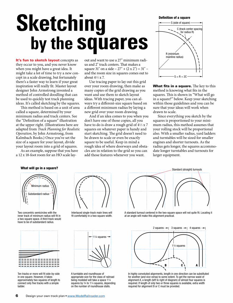
S = R + 2C
R (minimum mainline radius)
C (track center spacing for radius R)
S (side of square)
Definition of a square
Broad curves 20" 34" 48" 64"Conventional curves 16" 28" 38" 50"Sharp curves 13" 22" 32" 42" N HO S OSquares are of the following approximate sizes:
(Minimum track center spacing may be obtained from NMRA standard S-8)
CB A
11⁄2 squares
4 squares3 squares2 squares
11⁄4 squares
Standard (straight) turnouts
Substandard radius
Minimum radius
What will go in a square?
Two concentric semicircles with the inner track of minimum radius will fit in a two-square space. A third track would have to be of substandard radius.
Ten tracks or more will fit side-by-side in one square. However, it takes approximately two squares of length to connect only five tracks with a simple ladder.
A turntable and roundhouse of appropriate size for the class of railroad being modeled will take a space 11⁄4 squares by 3⁄4 to 11⁄4 squares, depending on the number of roundhouse stalls.
In highly convoluted alignments, length in one direction can be substituted for another (and vice versa) to some extent. To get the narrow waist of alignment A, a length (left to right of diagram) of almost four squares is required. If length of only two or three squares is available, extra width required for alignment B or C must be provided.
Interlaced single-track main lines will fit comfortably in a two-square width.
A standard turnout centered in the two-square space will not quite fit. Locating it at an angle will make this alignment practical.
6 Design your own track plan • www.ModelRailroader.com
It’s fun to sketch layout concepts as they occur to you, and you never know when you might have a great idea. It might take a lot of time to try a new con-cept in a scale drawing, but fortunately there’s a faster way to learn if your great inspiration will really fit. Master layout designer John Armstrong invented a method of controlled doodling that can be used to quickly test track planning ideas. It’s called sketching by the squares.
This method is based on a unit of area called a square, determined by your minimum radius and track centers. See the “Definition of a square” illustration at the upper right. (Illustrations here are adapted from Track Planning for Realistic Operation, by John Armstrong, from Kalmbach Books.) Once you’ve set the size of a square for your layout, divide your layout room into a grid of squares.
As an example, suppose that you have a 12 x 18-foot room for an HO scale lay-
Sketching by the squares
What fits in a square. The key to this method is knowing what fits in the squares. This is shown in “What will go in a square?” below. Keep your sketching within those guidelines and you can be sure that your ideas will work when drawn to scale.
Since everything you sketch by the squares is proportioned to your mini-mum radius, this method assumes that your rolling stock will be proportional also. With a smaller radius, yard ladders and turntables will be sized for smaller engines and shorter turnouts. As the radius gets longer, the squares accommo-date longer turntables and turnouts for larger equipment.
out and want to use a 27" minimum radi-us and 2" track centers. That makes a square 31" on a side – 27" + (2 x 2") = 31" – and the room size in squares comes out to about 42 ⁄3 x 7.
Use tracing paper to lay out this grid over your room drawing, then make as many copies of the grid drawing as you want and use them to sketch layout ideas. With tracing paper, you can al-ways try a different-size square based on a different minimum radius by laying a new grid over your room drawing.
And if an idea comes to you when you don’t have one of those copies, all you have to do is draw a rough grid of 42 ⁄3 x 7 squares on whatever paper is handy and start sketching. The grid doesn’t need to be drawn to scale or even be exactly square to be useful. Keep in mind a rough idea of where doorways and obsta-cles are in relation to the grid so you can add those features whenever you want.
Scale: 5⁄8" = 1'-0"6" grid
20"
Depot
17"
181⁄4"
17"
153⁄4"
141⁄2"
KEDDIE, CALIF.
N scale Keddie Terminal
West Yard
Keddie Wye
East Yard
151⁄2"
North toBeiber, Calif.
West toOakland, Calif.
Tunnel no. 32
East toSalt Lake City, Utah
No. 6
No. 6
No. 6
No. 6
No. 6
No. 6
Caboose track
Fuel track
Sand trackLocomotive service tracks
Train order officeBack track House track
Yard turnouts are no. 5
Twin water tanks
Wye tunnel
Steel bridges
27 cars
21 cars21 cars
Spanish Creek
Design your own track plan 7
Passing track
To Charleston, Ill. Nickel Platemain line
Old boxcar
Lumbershed
East wyeWest wye
Monon-to-NKP interchange Lumberyard
and scale Sky backdropStud wall
To Frankfort, Ind.U.S. 231
S.P. 43NKP-Monondepot
Mononmainline
Freighthouse
Field
Team track
Cattle loadingramp
Layout Design Elements
Illu
stra
tio
n b
y To
ny K
oes
ter
A good way to design a model railroad is to incorporate track arrangements and scenes based on the real thing. Tony Koester, editor of Model Railroad Planning maga-zine, calls these Layout Design Elements, or LDEs for short. For a small railroad you can pick one LDE as the focal point and design everything else around it. In a larger system you can string LDEs together – a yard, a station, a major industry, and so on – joined by segments of main line.
One advantage of LDEs is that they automatically look realistic because they’re taken from reality. Another is that your trains will be able to operate like the big ones because the LDE follows a real-life track arrangement.
You can find prototypes to use as LDEs in magazines, books, and railroad historical society publications. Also see Tony Koester’s book on LDEs, Realistic Model Rail-road Building Blocks, from Kalmbach Books.
The Linden, Ind., LDE shown below is from Tony’s book. Below that is an LDE based on the Western Pacific’s Keddie, Calif., junction and yard as rendered for a Model Railroader article by Jim Hediger. It shows that an LDE can be an extensive chunk of a model railroad.
When you find something you like, draw it to scale and convert its dimensions to squares. If you know that the large grain elevator complex you want to model needs ¾ x 3 squares, it’ll be easy to work it into your sketches.
Illustration by Rick Johnson
Linden, Ind.
8 Design your own track plan • www.ModelRailroader.com
The key to drawing an accurate track plan is being careful and correct with curves and turnouts. There are a couple of basic techniques to master and a shortcut to help with the most repeti-tive tasks. Think of these skills as foun-dations to support your imagination, and you’ll be able to both enjoy the fun of track planning and trust the practical-ity of your work.
Drawing curves with a compass is easy, and that’s mostly what you’ll need to do in designing a model railroad. If you’ve sketched your layout plan by the squares, you already know where the
major curves are going to be. Tape trac-ing paper over your space diagram, trace in the outline of the room, use an archi-tect’s scale to set your compass to your minimum radius, and draw arcs of that radius in the locations you’ve sketched.
Draw the arcs longer, through more degrees of curvature, than they need to be. That makes it easier to accurately connect them with straight lines. You can erase the excess arc after you’re satis-fied with the location of your main lines.
When you connect the curves with straight lines, align your rule so the pen-cil point barely touches the outside of the arc at each end. There are two good rea-
sons for this. The first is to make the line geometrically tangent to the arc. “Tan-gent” means a line touches a circle or arc at only one point, and is therefore auto-matically perpendicular to a line (a radi-us) drawn from the center of the arc or circle to that point. In other words, the straight track the line represents will meet the curve squarely, without a kink of sharper radius.
(This is the reason that railroaders and model railroaders alike often use the word “tangent” to mean straight track. In civil engineering terms, every piece of straight track on a railroad is tangent to a curve somewhere.)
Simple drafting tools will let you draw curves and turnouts with great accuracy. Jim Forbes photo
Drawing curves and turnouts accurately
Design your own track plan 9
Turnout dimensions N HO S OFrog no. 4 5 6 8 4 41/2* 5 6 8 4 5 6 8 4 5 6 8
Another reason for having the straight line barely touch the curve is to allow for transition, or easement, curves. These are spirals of gradually decreasing radius that allow engines and cars to move smoothly from a straightaway into a curve. Ease-ments not only look nice on a layout, they help trains run smoother by compensat-ing for the extreme sharpness of even the broadest model railroad curves.
Easements require an offset between the straight track and the constant-radius curve to allow room for the gradual transition to that radius. That offset is generally some fraction of an inch, how-ever, so the width of a pencil line is usu-ally enough to represent it on a small scale drawing.
(Note that half the length of the ease-ment will extend into the tangent, so al-
low for that too by not locating turnouts closer to the curve than that distance.)
You’ll also need to draw new curves taking off from straight lines. Start by aligning a triangle along your tangent so that the 90-degree corner is at the point where you want the curve to start. Then you can draw a line along the triangle that will be perpendicular to the straight line – the center of the curve will fall along that perpendicular line.
With your compass set to the desired radius, place the point on the perpendicu-lar line so the tip of the lead barely touch-es the tangent. Then you can swing the compass to draw the arc of that curve.
Don’t fudge on the relationship be-tween curves and tangents. Accuracy here will pay off in the construction and operation of your railroad.
Turnouts also call for careful draw-ing, both to construct accurate angles and to mark off relevant dimensions. The “Turnout dimensions” table gives the in-formation you need based on NMRA Recommended Practice RP-12 (www.nmra.org/standards/rp12.html). Not all turnouts necessarily match these recom-mendations – nor should they. If you’ll be using turnouts with other dimen-sions, such as scratchbuilt turnouts fol-lowing the specifications of your favorite prototype, use those measurements in your track plan.
The illustrations on the next two pag-es show how to lay out turnouts step by step and also give turnout frog angles for use with a protractor. Depending on the size of your protractor and the scale of your plan, this can be very accurate, but
Turnout dimensions
Q: Distance from switch point tointersection of center lines
L: Lead, distance from switchpoint to point of frog
C†: Overall length of curved leg ofturnout (measured as shown)
X: Offset between continuation of curve and straight leg of turnout
The table below gives key turnout dimensions for laying out center-line track diagrams accuratly enough to ensure that the alignment can be built in the indicated space. For
actually building turnouts, see NMRA Recommended Practice RP-12, from which these figures were derived. All dimensions are in inches, to the nearest 1⁄16".
† Dimensions given are minimums; for ready-to-use or kit turnouts substitute actual measurements from turnouts to be used. For example, Atlas HO no. 6: P = 11/2", S = 12", C = 10". Most sharp- and conventional-curve N scale ready-to-use turnouts are the curved-frog design, as are Peco Streamline
turnouts in all scales. These can best be laid out as arcs tangent to the straight-leg center lines and the actual dimensions C and P.* Atlas no. 4 HO turnout is actually no. 41/2. L, P, S, C, and X are shown for this turnout in the HO columns.
10 Design your own track plan • www.ModelRailroader.com
if you find it difficult to distinguish the protractor’s increments, you can defi-nitely rely on the method shown in the illustration above.
As with curves it often helps to extend straight lines from turnouts longer than they need to be and erase them later. It may allow you to mark the distance for a frog angle in larger units that are easier to read, and the extended lines can be useful in other ways. To lay out a yard
ladder, for example, extend the diverging line from the initial turnout, then draw body tracks parallel to the base line. Where the body tracks intersect the di-verging line are points of intersection for the turnouts in the ladder.
Templates are a shortcut for all this drafting. Commercial templates are available, and they’re easy to use if you’re satisfied with the scale, curve, and turn-
out choices they offer. But it’s not at all hard to make your own templates, as shown in the illustration on the opposite page. Then you’ll have exactly the curves and turnouts you want for your layout in the scale you’ve chosen for your drawing.
If your compass has a knife blade, it’s easy to cut the required arcs in clear ace-tate or styrene. You can do almost as well by scoring with a second point in a compass, but the knife blade will make neater cuts.
For the turnout template, use a hobby knife and score and snap out the wedge across the straight edge of the template. The same template works for drawing both right- and left-hand turnouts – just flip it over.
A deluxe set of track planning tem-plates might include at least three curves: the minimum radius, the radius for the outer track on a two-track curve, and a radius tighter than the minimum that you find acceptable for branch lines or industrial spurs. Similarly, you can include templates for your minimum turnout and two or three larger sizes you can use to avoid potential S-curve trou-ble in crossovers or just to look nice.
Laying out turnouts on track plans - 1
L
P
5
4 31
1 unit6 5 4 3 2 1
32 1
Q
A
8 71⁄6
6 91⁄2
5 111⁄2
41⁄2 121⁄2
4 141⁄4
3 19
Frog number Angle in degrees
* A protractor may be substituted for steps 1 through 4, using the angles below:
1. *Measure point-to-intersection distance Q from “Turnout dimensions” table.
2. *Measure number of units equal to turnout frog number – units may be of
any convenient length.
3. *Draw perpendicular and measure one unit.†
4. *Draw line through points 1 and 3.
5. Measure length L from “Turnout dimensions” table – this locates frog.
To lay out a turnout at a given location on a tangent, points to be at A: Centers of curves joining turnout must lie on perpendicular lines from track center lines through points measured in step 6, or beyond.
6. Measure distance P, then S, and then C for turnout type (NMRA, kit, or ready-to-use). This locates rail joints or other points at which curved track can join turnout.
C
S
† For equilateral or wye turnout, measure ½ unit on each side of straight center line.
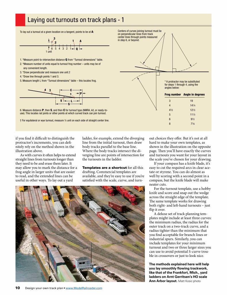
The methods explained here will help you lay smoothly flowing trackwork, like that of the Frankfort, Mich., yard ladders on Arnt Gerritsen’s HO scale Ann Arbor layout. Matt Kosic photo
As you find various bits of information, put them on the templates for ready reference
1 unit
41⁄2 units
Notch at exact center of curve
These locations vary with each make of turnout
Joint, curved side
Joint, straight side
1 unit
6 units
1" rise at 2
perc
ent
Templates will ease the task of drawing a track plan to scale, and can be especially useful in the cut-and-try process of finding the best alignment for key trackwork. The templates can be of any material, but heavy acetate or clear styrene will let you see your previous drawing through the template.
Cut to exact radius; extra space allowance caused by width of pencil line will be about enough to allow for easements on the actual railroad
Laying out turnouts on track plans - 2
Templates for track planning
To join a curve to a tangent through a turnout at a given location on a tangent, with the center of the curve at B and tangent to pass through C:1. Draw curve center lines of radii R and R + X (find X in “Turnout dimensions” table).2. Draw tangent from C to join curve R + X.3. Draw right angle from tangent to B – this locates the point of tangent offset PTO.4. Measure distance D equal to radius R divided by the frog number – this locates the point of curvature PC. Draw line from B to PC.5. Draw line from PC perpendicular to B-PC – where this crosses tangent is the point of intersection PI.6. Measure distances Q and L to each side of PI to locate point and frog of turnout.
12 Design your own track plan • www.ModelRailroader.com
NMRA S-7 clearance diagram
Railhead level
Upper track railhead level
H
R
Even as you draw in two dimensions you’ll want to start thinking of your model railroad as three-dimensional. Whenever you want a track to cross above another track or even over itself, you need to plan on a reasonable grade. Or you may want to build grades for sce-nic and operational reasons. In the hilly or mountainous country so popular with modelers, trains have to operate up and down grades. You may even want a grade steep enough to require helper or pusher engines, because of the additional oper-ating interest, to represent a favorite pro-totype, or both.
You also need to provide enough sep-aration so that trains on the lower level can pass under the supporting structure of the upper level track. That supporting structure may be your usual subgrade and roadbed, or it may be a model bridge. The distance between the rails of the lower track and the bottom of what-ever supports the upper track is called the clearance, and it must be sufficient for the kinds of trains you want to run.
The steepness of a railroad grade is defined by the number of units of rise or fall in 100 units of travel. A slope that rises one unit in 100 is called a 1 percent grade. One that rises two units in 100 is a 2 percent grade, and so on.
On model railroad track plans we of-ten show the lowest track elevation as zero and give elevations above that in
Figuring grades and clearances
inches. Starting from your zero point, you can measure 100 scale inches along the track and mark the elevation at that point for however many inches you wish to establish the steepness of the grade.
Or you can lay out a line climbing to a desired elevation and then measure to de-termine the percent of grade. Measure the distance in scale inches along the track between the lowest and highest elevations, divide the difference in elevation by that distance, and move the decimal point in the answer two places to the right.
Suppose you have a rise of 41/2" over a distance of 11'-3". Multiply 11 x 12 to convert to inches, add 3, and divide 4.5 by 135. That equals .0333, and after mov-ing the decimal point you can read the result as a grade of 3.33 percent.
That’s pretty steep, but if you don’t mind running short trains or using helper locomotives it may be okay. If you want to reduce the grade you must have the railroad gain less elevation over the given
distance, increase the distance, or man-age some combination of the two.
So how do we measure distance on a track plan? Since our tracks are of-ten more curved than straight we’re faced with the problem of measuring the length of twisting, turning lines. But you’ll usually already have one tool that can do this, your compass. You can use it with the pencil point in place, but it’ll keep the drawing neater if you replace that with a second metal point, turning the com-pass into a pair of dividers.
Using your scale, set the dividers to some convenient measurement, then use
Clearance table
*For more details see www.nmra.org/standards/s-7.html
N HO S OH: NMRA S-7 clearance* 121⁄32" 3" 41⁄8" 51/2"
R: Recommended railhead-to-railhead separation
27⁄32" 4" 51⁄2" 73 ⁄8"
The 2.2 percent grade up to Summit, Calif., on Ted York’s HO scale Atchison, Topeka & Santa Fe Ry. Cajon Pass layout adds to the fun by requiring pusher locomotives to help heavy freights make the climb. Ted York photo
Design your own track plan 13
them to step off the distance along the track while you count the steps. If you set the dividers to a scale 10", ten steps equal 100" and you can mark an eleva-tion at that point to indicate the desired grade. Or set the dividers to a scale foot and step off the distance to a given eleva-tion in feet. Multiply the number of steps by 12 to convert feet to inches and divide that distance into the elevation to find the grade.
There’s a degree of error in measuring curves with dividers – in geometric terms you’re measuring chords between points on an arc instead of the circum-ference of the arc itself – but all that means is that the grade will be a small fraction of a percent steeper than indi-cated. Usually close is good enough, or you can deliberately mark out a slightly gentler grade than you want to build.
For greater accuracy, a simple length of soft copper wire can be a useful mea-suring instrument. Bend it to follow the line of your track, put sharp bends at each end of the distance to be measured, then straighten the wire between the sharp bends and measure the straight-line distance with your scale. Or you can use a measuring wheel called an opisom-eter that you can steer along the line of your track. Usually these have scales in inches and you’ll have to convert the measurements to your drawing scale. There are also digital versions that can make scale conversions for you.
Overhead clearance requirements for each scale are given in the clearance table on page 12. These are taken from NMRA standard S-7 and represent the ideal prototype clearance of 22 feet above the rail (with some approximation – in HO 22 feet is 33 ⁄64".)
Real railroads don’t always have this much clearance, and you don’t need to either. But if you’re going to skimp you should know the scale height of your rolling stock and maintain enough clear-ance for it. Be aware as well that models are sometimes taller than they should be in scale.
Remember to allow for the structure supporting overhead tracks, whether it’s a scale model bridge or simply the ply-wood and roadbed combination under your trackwork. Either way it needs to be included in the railhead-to-railhead measurements indicated by track plan el-evations. (Where one hidden track cross-es over another, you can gain clearance by using short lengths of a thin, stiff ma-terial like Masonite hardboard to sup-port the upper track.)
A scale bridge deck structure can range from about three feet to more than six feet deep, depending on the type and length of the bridge. In HO three feet is 13 ⁄32", and code 83 flextrack is 3 ⁄16" thick. If you plan for 3" from railhead to railhead where a track passes under a bridge,
you’re really allowing at most 213 ⁄32", or a scale 17'-6". That’s too little for the big-gest modern cars, although older, small-er rolling stock may be okay. The clear-ance table on the opposite page gives recommended separations for track planning purposes.
Characteristics of grades
Railroads would avoid grades if they could, because climbing them increases operating expenses by limiting the length of trains and requiring more and heavier locomotives. In reality this is impractical. Even flat-looking country has some slope, and of course there are hills and mountains that have to be crossed. Railroads often follow watercourses to find the easiest path through the terrain, but the streams and rivers wouldn’t be flowing if they weren’t moving downhill toward sea level.
On a model railroad we may need grades to achieve a desired routing, and we may also use them to help portray particular types of railroading. The descriptions below relate grades to the kinds of railroads that use them.
0 to .99 percent: Except in the flattest terrain, grades as gentle as .3 or .5 percent often require extra earthwork, bridges, and length of run. These expenses may be justified only if traffic is unusually heavy. The former New York Central advertised its New York-Chicago main line as the Water Level Route because most of its grades were less than .5 percent (with the famous exception of the Central’s 1.6 percent climb out of the Hudson River Valley at West Albany Hill).1 to 1.99 percent: A grade of 1 percent, such as on the former Western Pacific line through the Feather River Canyon, is a moderate grade for crossing mountains. The Pennsylvania RR (now Norfolk Southern) climb through the famous Horseshoe Curve is on a grade of 1.86 percent.2 to 2.99 percent: When Congress passed land grant laws to subsidize 19th-century railroad construction in the West, it specified that grades on the new lines could not be steeper than then existed on the Baltimore & Ohio. This required the builders of the pioneering Central Pacific and Union Pacific to maintain grades of 2.2 percent or less.3 to 3.99 percent: Mainline railroads on grades this steep are unusual and found only in rugged terrain. The Santa Fe’s line over Raton Pass on the Colorado-New Mexico border was built on a grade of 3.5 percent, leading the railroad to build a second route farther south to carry the bulk of its transcon-tinental freight traffic on grades not exceeding 1.25 percent.4 percent and steeper: The steepest mainline grade in the United States is the 4.7 percent Norfolk Southern line over Saluda Mountain in North Carolina. It’s more common to find grades that steep on cheaply constructed logging and mining railroads. Seven percent is about the practical limit for normal adhesion and in steam days required special gear-driven locomotives.
Sand on the rails and the smoke plume from the class Y6b 2-8-8-2 show what hard work was required to lift Norfolk & Western coal trains up the 1.2 percent Blue Ridge Grade at Blue Ridge, Va. Tom Miller photo
14 Design your own track plan • www.ModelRailroader.com
There’s more to a model railroad than just the track, and typically you’ll want a track plan to indicate the loca-tions of at least the most important structures and scenic features. There also has to be room for people to build and enjoy the layout, or the plan won’t be much use. It’s easy to account for all this as you’re designing a layout – just leave room for other things besides track.
When you draw a structure on a track plan you need to know the size and shape of the building’s footprint, and you need to keep it far enough away from the track. The first piece of infor-
mation is often available from kit mak-ers, in their catalogs or on their websites. Kit reviews in Model Railroader and oth-er magazines usually specify the foot-print also. If you plan to scratchbuild a structure, use the dimensions from the prototype plan. When you draw in a building to scale, you know it will fit where you want it.
As long, that is, as you allow sufficient clearance from the track center line. It’s a trap to cheat on this or simply not to consider that the track represented by a center line is wider than the pencil trace. The trains that will run on the track are wider still. Allow for this as shown in the
“Clearance for structures” diagram on the opposite page. You’ll need to provide even greater clearance along curved track or where the building is to be set back from the track.
Room for slopes can be the key to re-alistic, believable scenery. This requires that you maintain some horizontal sepa-ration between tracks at different eleva-tions. Except when you want to model an elevated roadbed through a city,avoid stair-stepped ledges and extensive retaining walls.
In open country allow room for the cuts and fills the railroad uses to main-tain a steady grade across undulating terrain. Allow for cuts especially as track
Structures, scenery,andaisles
Realistic slopes along the bank of a mountain creek contribute to a dramatic scene of Sierra Nevada railroading on Pelle Søeborg’s HO layout. Pelle Søeborg photo
Bloomington, Ind., on Lance Mindheim’s N scale Monon layout included space for buildings and streets as well as the railroad and its downtown industrial tracks. The investment in real estate helped to make passing through Bloomington a notable event in any train’s trip across the layout’s mostly rural landscape. Paul Dolkos photo
Design your own track plan 15
Possible extension
30" aisles along 8-foot sides of table layout
30" door
4x8-foot table layout in center of room
24" aisles along 4-foot side of table layout
24"-deep 8x10-foot shelf layout along two wallsPossible extension
Two ways to put a layout in a 9 x 12-foot room
Gauge side of rail
P
Loading platform
A
Center line of track
approaches a tunnel, to keep the actual bore as short as possible.
Slopes are also important along streams. Outside of very rugged terrain, the banks of a river or creek should have mostly gentle slopes. Meandering creeks may have steep banks, but then their curvature makes them fairly wide fea-tures in the landscape.
Streets and highways also take more space than you might think. A scale 20-foot width may look okay for a two-lane roadway in model scenes, but that’s tight for modern vehicles. A 25- or 30-foot width will be more realistic for two lanes. And don’t forget to allow for sidewalks.
Whenever possible allow room for scenery and even structures between the front-most track and the layout edge. This puts the railroad in the scene in-stead of in front of it, and seeing trains pass behind some features adds interest.
Room for people is important too. As the diagram shows, a 4 x 8-foot table lay-out can dominate a 9 x 12-foot room and restrict passage around it. That 4 x 8-foot sheet of material can be split down the middle to form an along-the-walls shelf layout that leaves much more free space in the middle of the room.
For walk-in layouts, try to maintain 30" aisles, with more width at frequent intervals to make it easier for people fol-lowing their trains to pass each other.
(If you’re sketching by the squares as shown on page 6, allow a full square’s width for an aisleway of an HO layout. The same aisle will be as wide as two
squares in an N scale layout, and less than one square wide for O scale.)
Aisles of 36" or even 42" width will make building, viewing, and operating the layout much more comfortable. Still wider aisles can be a good idea at yards and other places where trains and hence operators tend to congregate.
Suggested reading for layout designers
Clearance for structures
Realistic Model Railroad Operation, 2nd edition, by Tony KoesterRealistic Model Railroad Design, by Tony KoesterTrack Planning for Realistic Operation, 3rd edition, by John ArmstrongBuilding a Model Railroad Step by Step, 2nd edition, by David Popp
All published by Kalmbach Books. Ask for them at your Kalmbach dealer, call 800-533-6644, or visit ModelRailroader.com.
N HO S OFrom centerof track – A*
19 ⁄32" 11⁄32" 113 ⁄32" 17⁄8"
For loading platform – P*
15 ⁄32" 13 ⁄32" 11⁄8" 11⁄2"
* Allow additional clearance along curved track; for more detail see NMRA standard S-7 at www.nmra.org/standards/s-7.html