ABSTRACTNear-field communication (NFC) plays a crucial role in theoperation of mobile devices to enhance applications such aspayment, social networks, private communication, gaming,and etc. Despite of the convenience, existing NFC standardslike ISO-13157 require additional hardware (e.g., loop antennaand dedicated chip) and thereby hindering their wide-scale ap-plications. In this work, we seek to propose a novel near-fieldcommunication protocol, MagneComm, which utilizes Mag-netic Induction (MI) signals emitted from CPUs and capturedby magnetometers on mobile devices for communication. SinceCPUs and magnetometers are readily available components inmobile devices, MagneComm eliminates the requirement forspecial hardware and complements existing near-field com-munication protocols by providing additional bandwidth. Wesystematically analyze the characteristics of magnetic signalsof CPUs and facilitate MagneComm with one-way commu-nication, full-duplex communication, and multi-transmitterschemes in accordance with the hardware availability on de-vices. We prototype MagneComm on both laptops and smart-phones. Extensive evaluation results show that MagneCommachieves up to 110 bps within 10 cm.
CCS CONCEPTS• Human-centered computing → Mobile computing; Ubiq-uitous and mobile computing systems and tools; • Securityand privacy → Mobile and wireless security;
KEYWORDSnear-field communication; magnetic induction; full-duplex
1 INTRODUCTIONNear-field communication (NFC) has been attracting consider-able attention in recent years as it is facilitating a wide rangeof applications, including mobile payment, social networks,interactive gaming and etc. Nowadays, even the NFC moduleis integrated on major-brand smartphones, there is still a largeportion of them without NFC due to the stringent requirementof NFC chips. Current NFC implementation is based on theISO-13157 [19] standard which requires dedicated hardware,i.e. the NFC chip module consisting of an antenna and electriccircuits for coding and decoding. The need for NFC chip, how-ever, incurs extra costs and enlarges volume to size-limitedsmarthones and therefore greatly limits the applicability ofNFC. On the other hand, even for NFC-capable devices, theNFC function is sometimes limited, e.g., NFC on iPhones onlysupports Apple Pay.
A number of alternative methods have been devised to al-leviate the pain brought by the standard NFC implementa-tion. Typical examples are Bluetooth, acoustic [15, 27], visiblelight [17, 21, 25] and etc. Most of these approaches rely oncommodity hardware or built-in sensors. Among them, Blue-tooth is a popular technique and applied for short-range com-munication on mobile devices. However, existing alternativeimplementations of NFC also face problems. First, they arevulnerable to security issues. For example, Bluetooth worksin a relatively longer communication range than the standardNFC and it is easy for attackers to eavesdrop the transmitted in-formation. Second, the communication channels endure noiseand interference, e.g., Bluetooth is easily interfered with WiFisignals, not to mention the acoustic and the visible-light ap-proaches. Therefore, existing alternative NFC implementationsfail to satisfy both the security and performance requirements.
In this paper, we try to provide an NFC implementationscheme without dedicated hardware while keeping the secu-rity and performance concerns in mind. We adopt MagneticInduction (MI) signal emitted from mobile devices as a com-munication channel and exploit the build-in magnetometer forsignal reception. Specifically, we elaborately control the CPUmodule for transmission of MI signals, and the magnetometersequipped on commodity mobile devices for signal decoding.By carefully regulating the MI signals emitted from CPUs, andsensing it with the magnetometers on devices, two devices areable to communicate in a near-field manner. We develop thisconcept into a full-duplex communication system (referred toas MagneComm) using techniques such as pulse width and
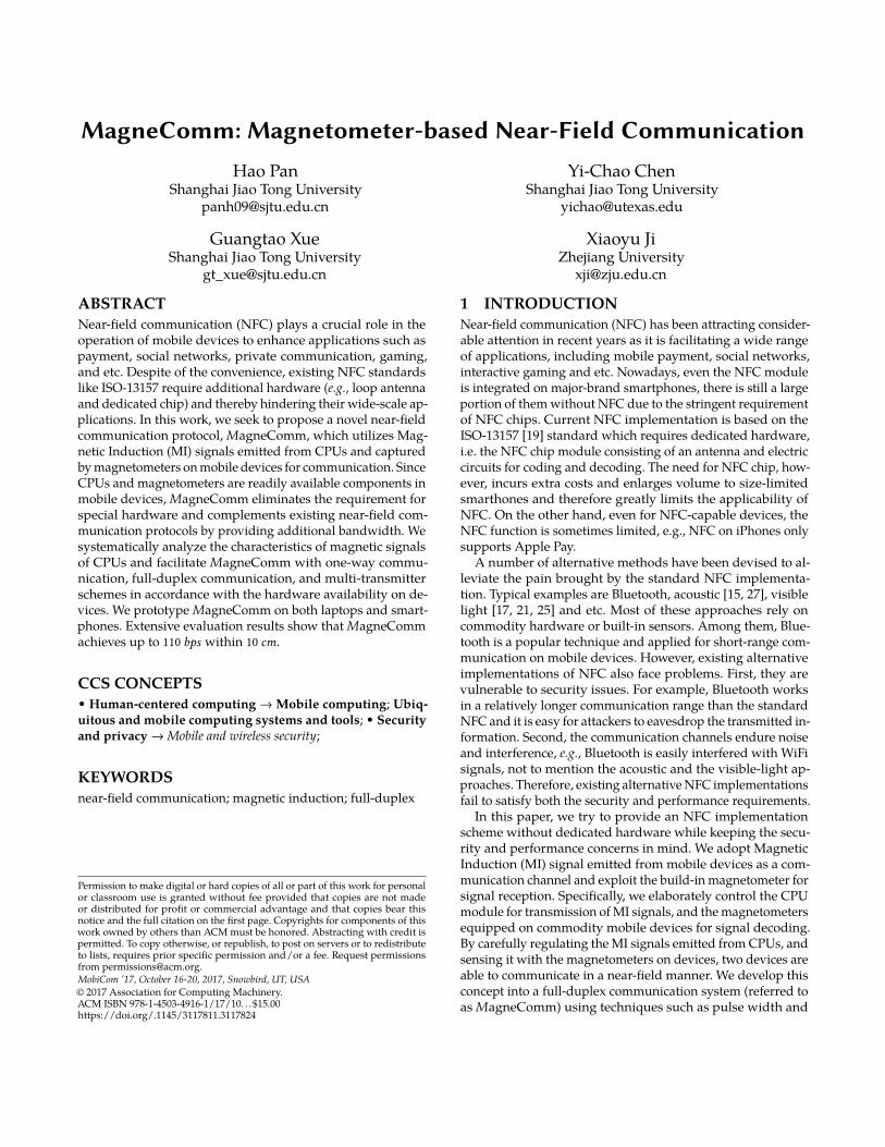
amplitude modulation, channel estimation, proactive retrans-mission, and self-signal cancellation. The overall architectureof MagneComm is shown in Fig. 1 from a layered perceptive.
The design of MagneComm poses a number of difficult chal-lenges. First, precise control over CPU by job scheduling inoperation systems (OS) to generate suitable MI signals is com-plicated. With this constraint, complex modulation schemes,such as OFDM (orthogonal frequency division multiplexing)are essentially infeasible. We first investigate the character-istics of MI signals from extensive experiments and finallycombine the pulse width with amplitude modulation as thefundamental modulation scheme to strike a balance betweentransmission speed and accuracy. Second, concurrent runningjobs on CPUs bring about interference during the transmissionprocess, and thus increase confusion when detecting CPU’s MIsignals. To guarantee the quality of transmission in noisy envi-ronments, we design a preamble for signal detection and anda retransmission scheme. The retransmission scheme monitorsthe real-time CPU usage and the bit error distribution, andretransmits the previous corrupted packet if necessary. Third,to overcome the low sampling rate of the magnetometers onmobile devices, we adopt multiple transmitters in order toimprove the transmission rate. We also exploit signal cancella-tion technique and design a subtraction algorithm to realizefull-duplex communication, when both the two devices areequipped with magnetometers.
We implement the MagneComm prototype and evaluate thecommunication between laptops and smartphones, as well asbetween two laptops. The coded MI signals can be successfullycaptured and decoded by the magnetometers on smartphonesand laptops. When MagneComm is applied between two lap-tops, a self-signal cancellation algorithm is applied at the ter-minal of the transmitter to counterbalance MI signals fromits own CPU, thereby enabling dual-duplex communication.In our experiments, MagneComm is able to achieve through-put of up to 110 bps in average between two laptops, 12 bpsbetween a laptop and a smartphone. Our prototype supportsan operating range of up to 10 centimeters between devices.
MagneComm can flourish abundant applications. For ex-ample, the designed MagneCode built upon MagneComm
can enable an extended screen to obtain more information onmobile devices. The details of applications and their imple-mentations are discussed in Sec. 7. The main contribution ofthis work can be summarized as follows:• We propose MagneComm, a novel implementation scheme
of NFC which eliminates the need for dedicated hard-ware by embedding data stream into the MI signals of aCPU without affecting the normal function of the device.• A variety of communication schemes are devised using
this system, including one-way, full-duplex and multipletransmitter communication to take full advantage of thefunctionality of the communication devices.• We prototype the communication system between a lap-
top and a smartphone as well as between two laptops.Evaluation results demonstrate the efficacy of MagneComm.
The rest of this paper is organized as follows: In Sec. 2, we in-troduce the working principle of the magnetometer and CPU.In Sec. 3, we outline the characteristics of the MI signals gener-ated by CPUs. In Sec. 4, we present the proposed transmissionand reception protocols. The prototypes on smartphones andlaptops are described in Sec. 5 and evaluations are describedin Sec. 6. Future implementations of the proposed system areoutlined in Sec. 7. Conclusions are drawn in Sec. 9.
2 BACKGROUNDIn this section, we outline the working principle of magne-tometers and the emission of Magnetic Induction (MI) signalsfrom laptops. These are the fundamental issues related to thedesign of MagneComm.
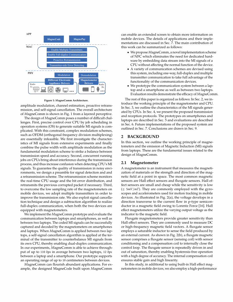
2.1 MagnetometerA magnetometer is an instrument that measures the magneti-zation of materials or the strength and direction of the mag-netic field at a point in space. The most common magneticsensors are Hall effect sensors and fluxgate sensors. Hall ef-fect sensors are small and cheap while the sensitivity is low(≤ 5mV /mT ). They are commonly employed with the gyro-scopes and accelerometers used for motion tracking in mobiledevices. As illustrated in Fig. 2(a), the voltage develops in adirection transverse to the current flow in p-type semicon-ductor in a magnetic field owing to Lorentz Force [16]. Halleffect magnetometers utilize the varying output voltage as theindicator to the magnetic field.
Fluxgate magnetometers provide greater sensitivity thanHall effect sensors. They are commonly used to measure DCor high-frequency magnetic field vectors. A fluxgate sensoremploys a saturable inductor to sense the field produced byan external current. As shown in Fig. 2(b), a fluxgate magneticsensor comprises a fluxgate sensor (sensing coil) with sensorconditioning and a compensation coil to internally close thecontrol loop. The fluxgate sensor is repeatedly driven in andout of saturation, thereby enabling hysteresis-free operationwith a high degree of accuracy. The internal compensation coilensures stable gain and high linearity.
In this study, in additional to using built-in Hall effect mag-netometers in mobile devices, we also employ a high-performance
N
S
Magnet
Directional
Magnetic
Field (H)
+ + + + + +
- - - - - -
i
DC Supply
Constant
Current Flow
Semiconductor
Hall Element
VH+
-Hall
Voltage
(a) Hall effect sensor.
Bext
Magnetic
CoreCompensation
Coil
Sensing Coil
Vexc
Vsense
(b) Fluxgate sensor.
Figure 2: The working principle of two types of magnetometers.
fluxgate sensor, DRV425 from TI [7], to understand the im-pact of various magnetometers. The output analog signalsfrom DRV425 are sampled by an ADC chip (ADC7606) con-trolled through STM32F107 Microcontroller Unit. The sam-pling rate of the ADC is set to 10KHz with 12-bit output reso-lution (up to 0.15nT per bit). Although higher sampling rates(up to 50KHz) are possible, Magnetic Induction signals fromthe CPU presents little between 10KHz and 50KHz so a highersampling rate would only increase the burden of data analysiswithout providing any benefit.
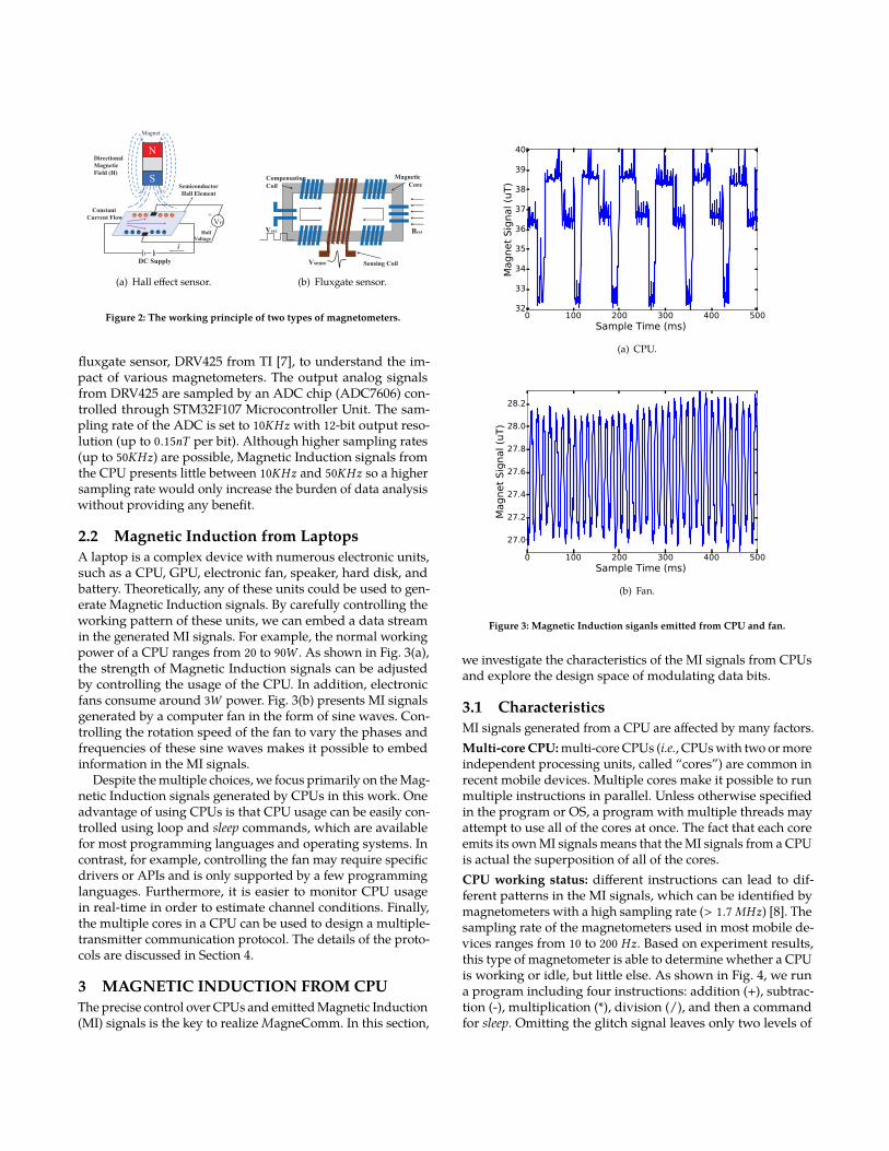
2.2 Magnetic Induction from LaptopsA laptop is a complex device with numerous electronic units,such as a CPU, GPU, electronic fan, speaker, hard disk, andbattery. Theoretically, any of these units could be used to gen-erate Magnetic Induction signals. By carefully controlling theworking pattern of these units, we can embed a data streamin the generated MI signals. For example, the normal workingpower of a CPU ranges from 20 to 90W . As shown in Fig. 3(a),the strength of Magnetic Induction signals can be adjustedby controlling the usage of the CPU. In addition, electronicfans consume around 3W power. Fig. 3(b) presents MI signalsgenerated by a computer fan in the form of sine waves. Con-trolling the rotation speed of the fan to vary the phases andfrequencies of these sine waves makes it possible to embedinformation in the MI signals.
Despite the multiple choices, we focus primarily on the Mag-netic Induction signals generated by CPUs in this work. Oneadvantage of using CPUs is that CPU usage can be easily con-trolled using loop and sleep commands, which are availablefor most programming languages and operating systems. Incontrast, for example, controlling the fan may require specificdrivers or APIs and is only supported by a few programminglanguages. Furthermore, it is easier to monitor CPU usagein real-time in order to estimate channel conditions. Finally,the multiple cores in a CPU can be used to design a multiple-transmitter communication protocol. The details of the proto-cols are discussed in Section 4.
3 MAGNETIC INDUCTION FROM CPUThe precise control over CPUs and emitted Magnetic Induction(MI) signals is the key to realize MagneComm. In this section,
0 100 200 300 400 500
Sample Time (ms)
32
33
34
35
36
37
38
39
40
Magnet
Sig
nal (u
T)
(a) CPU.
0 100 200 300 400 500
Sample Time (ms)
27.0
27.2
27.4
27.6
27.8
28.0
28.2
Magnet
Sig
nal (u
T)
(b) Fan.
Figure 3: Magnetic Induction siganls emitted from CPU and fan.
we investigate the characteristics of the MI signals from CPUsand explore the design space of modulating data bits.
3.1 CharacteristicsMI signals generated from a CPU are affected by many factors.Multi-core CPU: multi-core CPUs (i.e., CPUs with two or moreindependent processing units, called “cores”) are common inrecent mobile devices. Multiple cores make it possible to runmultiple instructions in parallel. Unless otherwise specifiedin the program or OS, a program with multiple threads mayattempt to use all of the cores at once. The fact that each coreemits its own MI signals means that the MI signals from a CPUis actual the superposition of all of the cores.CPU working status: different instructions can lead to dif-ferent patterns in the MI signals, which can be identified bymagnetometers with a high sampling rate (> 1.7MHz) [8]. Thesampling rate of the magnetometers used in most mobile de-vices ranges from 10 to 200 Hz. Based on experiment results,this type of magnetometer is able to determine whether a CPUis working or idle, but little else. As shown in Fig. 4, we runa program including four instructions: addition (+), subtrac-tion (-), multiplication (*), division (/), and then a commandfor sleep. Omitting the glitch signal leaves only two levels of
0 200 400 600 800 1000 1200 1400
Time (ms)
30
32
34
36
38
Magnet
Sig
nal (u
T)
+ - x ÷
sleep
Figure 4: Emitted MI signals while CPU executingvarious instructions.
0
1
2
3
4
5
6
7
8
9
0 5 10 15 20 25
∆ M
I Am
plitu
de (
uT)
Distance (cm)
HP Envy 14
DELL Inspirn 15
ThinkPad T440
MacBookPro13
Figure 5: The amplitude change of MI signals of oneCPU core at different distances.
00->Level1
01->Level2
10->Level3
11->Level4
T 2T 3T 4T
40%
01
60%
10
20%
00
80%
11
“0001” “1110” “1000” “0111”
Figure 6: Example of PWAM data symbols.
magnitude in the MI signals, corresponding to the status ofthe machine (working and idle).
Distance: the magnitude of the MI signal is inversely pro-portional to the cube of the distance traveled. Furthermore,the material with which the case of the mobile device is con-structed may also affect the magnitude, due to the shieldingeffect. Fig. 5 shows the changes in the magnitude of MI signalsover distance, as measured using various types of laptops. Ateach distance, we measure MI signals when the CPU is in work-ing and idle states, and calculate the magnitude difference be-tween two states. We can see that at distances exceeding 10 cm,the magnitude change becomes too small to be distinguishedby DRV425 magnetometer with the sensitivity of 0.16 uT .
3.2 Controlling Magnetic Induction SignalsIn the following, we examine the methods used to controlMagnetic Induction and modulate data.
Modulation: regular magnetometers can only measure theworking and idle status of a CPU core; therefore, one intuitiveway to embed data is to use On-Off Keying. That is, we switcha CPU core between idle and working to represent 0 and 1,respectively. For a 200Hz magnetometer, switching CPU statusevery 5ms would enable a data transmission rate of 200bps.However, in most practical situations, it is difficult to controlthe CPU in this manner. Furthermore, On-Off keying is subjectto noise generated by background programs.
We therefore selected Pulse Width and Amplitude Modu-lation (PWAM) which combines the Pulse Width Modulation(PWM) and Pulse Amplitude Modulation (PAM) to modulatedata. Specifically, each data symbol has period T and is pre-sented using the proportion of CPU working time during thatperiod. A data symbol consists of M+N data bits, where M bitsare translated to a set of pre-defined 2M levels of amplitude ofCPU magnetic induction signals (PAM), N bits are translatedto a set of pre-defined 2N levels of CPU working percentage(PWM). Take Fig. 6 as an example, each data symbol is 30mslong and consists of 4 bits. The amplitude of each symbol couldbe 1, 4, 3, 2 which represents data bits: 00, 11, 10 and 01. TheCPU working percentage of each symbol could be 40%, 60%,20%, 80% which represents bits: 01, 10, 01 and 11, respectively.We can adjust T , M and N according to the current channelcondition as well as how precise we can control a CPU core.
020406080
100
Core
1 (
%)
020406080
100
Core
2
020406080
100
Core
3
0 50 100 150 200 250 300
Samples
020406080
100
Core
4
(a) Doing Nothing
020406080
100
Core
1 (
%)
020406080
100
Core
2
020406080
100
Core
3
0 50 100 150 200 250 300
Samples
020406080
100
Core
4
(b) Watching Offline Video
020406080
100
Core
1 (
%)
020406080
100
Core
2
020406080
100
Core
3
0 50 100 150 200 250 300
Samples
020406080
100
Core
4
(c) Watching Live Stream Video
020406080
100
Core
1 (
%)
020406080
100
Core
2
020406080
100
Core
3
0 50 100 150 200 250 300
Samples
020406080
100
Core
4
(d) Surfing Websites
020406080
100
Core
1 (
%)
020406080
100
Core
2
020406080
100
Core
3
0 50 100 150 200 250 300
Samples
020406080
100
Core
4
(e) Playing Games
020406080
100
Core
1 (
%)
020406080
100
Core
2
020406080
100
Core
3
0 50 100 150 200 250 300
Samples
020406080
100
Core
4
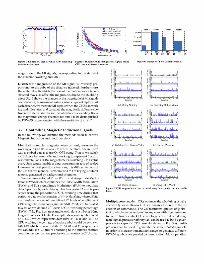
(f) Using Office WordFigure 7: CPU usage of each core recorded every 50ms under various condi-tions.
Multiple cores: modern OSes optimize the scheduling of tasksspecifically for multi-core CPUs to ensure efficiency in the ex-ecution of commands. The OS maintains queues of globaltasks, which can be assigned to any core with free resources.In controlling specific CPU cores to generate a desired mag-netic signal, processor affinity [26] can be used to bind a givenprocess to a specific CPU core. As shown in Fig. 3(a), multi-ple cores can be used to generate the same PWAM symbolsin order to increase transmission range, or generate differentPWAM symbols for parallel communication. Most operating
Packet
Data
Retransmission
or Not?
Pulse Width &
Amplitude
Modulation
Real-time
CPU Usage
Monitoring
Interference
Detector
Code: loop
and sleep
Captured
Magnet
Sensor Data
Preamble
Detection
Symbol
Segmentation
& Demodulation
Output
Data
CPU MI
SignalReception
Transmission
Transmitter
Receiver
Adding
Preamble
Yes
Proactive Retransmission
Input
Data
Channel
Estimation
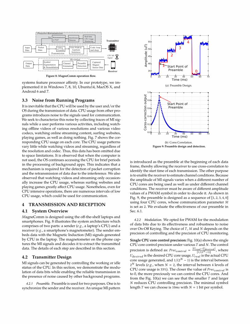
Figure 8: MagneComm operation flow.
systems feature processor affinity. In our prototype, we im-plemented it in Windows 7, 8, 10, Ubuntu14, MacOS X, andAndroid 6 and 7.
3.3 Noise from Running ProgramsIt is inevitable that the CPU will be used by the user and/or theOS during the transmission of data. CPU usage from other pro-grams introduces noise to the signals used for communication.We seek to characterize this noise by collecting traces of MI sig-nals while a user performs various activities, including watch-ing offline videos of various resolutions and various videocodecs, watching online streaming content, surfing websites,playing games, as well as doing nothing. Fig. 7 shows the cor-responding CPU usage on each core. The CPU usage patternsvary little while watching videos and streaming, regardless ofthe resolution and codec. Thus, this data has been omitted dueto space limitations. It is observed that when the computer isnot used, the OS continues accessing the CPU for brief periodsin the processing of background apps. This indicates that amechanism is required for the detection of packet corruptionand the retransmission of data due to the interference. We alsoobserved that watching videos and streaming only occasion-ally increase the CPU usage, whereas surfing websites andplaying games greatly affect CPU usage. Nonetheless, even forCPU intensive operations, there are numerous intervals of lowCPU usage, which could be used for communication.
4 TRANSMISSION AND RECEPTION4.1 System OverviewMagneComm is designed using the off-the-shelf laptops andsmartphones. Fig. 8 illustrates the system architecture whichcomprises of two parts: a sender (e.g., a laptop’s CPU) and areceiver (e.g., a smartphone’s magnetometer). The sender em-beds data with the Magnetic Induction (MI) signals generatedby CPU in the laptop. The magnetometer on the phone cap-tures the MI signals and decodes it to extract the transmitteddata. The details of each step are described in this section.
4.2 Transmitter DesignMI signals can be generated by controlling the working or idlestatus of the CPU. In this section, we demonstrate the modu-lation of data bits while enabling the reliable transmission inthe presence of noise caused by other background programs.
4.2.1 Preamble. Preamble is used for two purposes. One is tosynchronize the sender and the receiver. An unique MI pattern
0 10 20 30 40 50 60 70
Time (ms)
35
40
45
50
55
Am
plitu
de (
uT)
1
2
3
4
0
Start Point of Preamble
(a) Preamble Design.
0 10 20 30 40 50 60 70
Time (ms)
0.0
0.2
0.4
0.6
0.8
1.0
Cors
s-c
orr
ecti
on o
utp
ut
Start Point of Preamble
(b) Corss Correlation.Figure 9: Preamble design and detection.
is introduced as the preamble at the beginning of each dataframe, thereby allowing the receiver to use cross-correlation toidentify the start time of each transmission. The other purposeis to enable the receiver to estimate channel conditions. Becausethe amplitude of MI signals varies when a different number ofCPU cores are being used as well as under different channelconditions. The receiver must be aware of different amplitudevalues of a PWAM symbol in order to decode it. As shown inFig. 9, the preamble is designed as a sequence of [1, 2, 3, 4, 0]using four CPU cores, whose communication parameter Mis set as 2. We evaluate the effectiveness of our preamble inSec. 6.1.
4.2.2 Modulation. We opted for PWAM for the modulationof data bits due to its effectiveness and robustness to noiseover On-Off Keying. The choice ofT , M and N depends on theprecision of controlling and the precision of CPU monitoring.
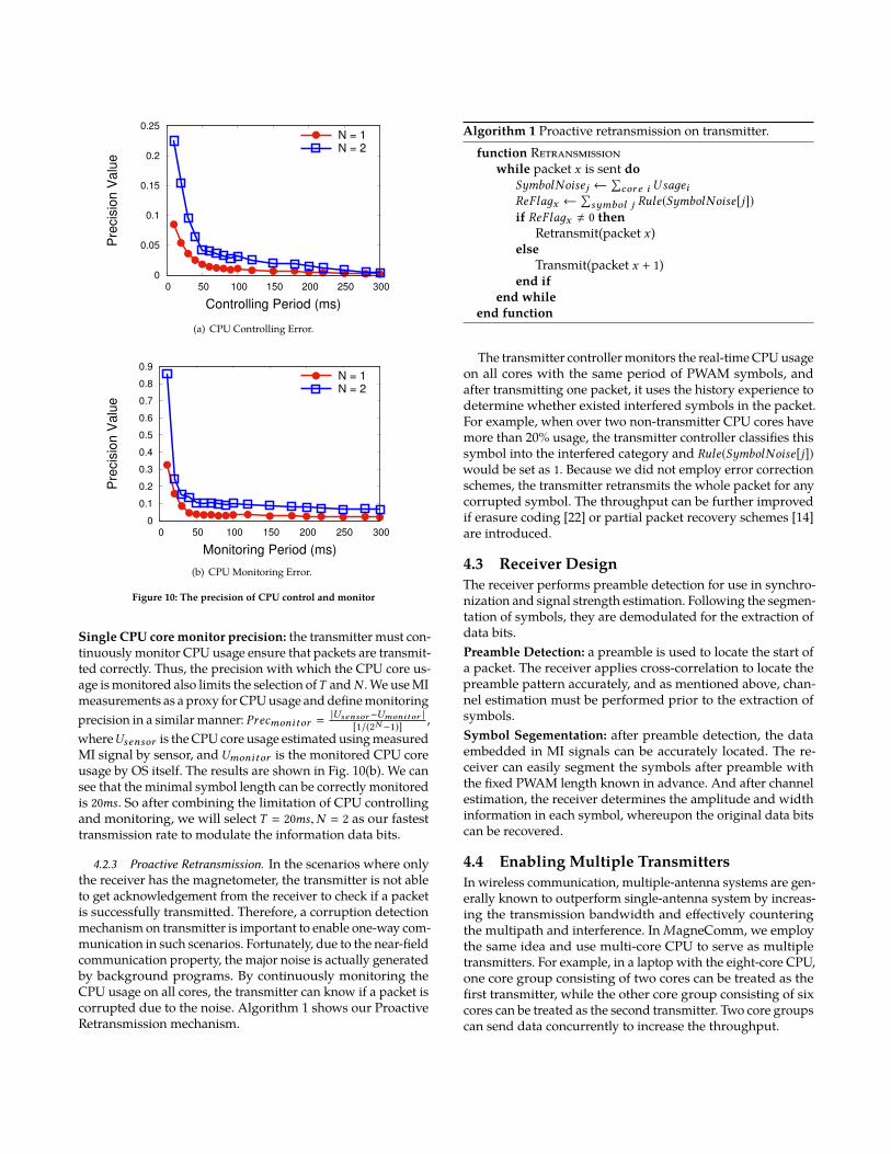
Single CPU core control precision: Fig. 10(a) shows the singleCPU core control precision under variousT and N . The controlprecision is defined as: Preccontrol =
|Ur eal−Udesir ed |[1/(2N −1)] , where
Udesir ed is the desired CPU core usage,Ur eal is the actual CPUcore usage generated, and 1/(2N − 1) is the interval between2N levels (e.g., when N = 2, the interval between 4 levels ofCPU core usage is 33%). The closer the value of Preccontrol isto 0, the more preciously we can control the CPU cores. Andfrom the Fig. 10(a) we can see that the smaller T and largerN reduces CPU controlling precision. The minimal symbollength T we can choose is 10ms with N = 1 bit per symbol.
0
0.05
0.1
0.15
0.2
0.25
0 50 100 150 200 250 300
Pre
cis
ion
Va
lue
Controlling Period (ms)
N = 1N = 2
(a) CPU Controlling Error.
0
0.1
0.2
0.3
0.4
0.5
0.6
0.7
0.8
0.9
0 50 100 150 200 250 300
Pre
cis
ion
Va
lue
Monitoring Period (ms)
N = 1N = 2
(b) CPU Monitoring Error.
Figure 10: The precision of CPU control and monitor
Single CPU core monitor precision: the transmitter must con-tinuously monitor CPU usage ensure that packets are transmit-ted correctly. Thus, the precision with which the CPU core us-age is monitored also limits the selection ofT andN . We use MImeasurements as a proxy for CPU usage and define monitoringprecision in a similar manner: Precmonitor =
|Usensor−Umonitor |
[1/(2N −1)] ,whereUsensor is the CPU core usage estimated using measuredMI signal by sensor, and Umonitor is the monitored CPU coreusage by OS itself. The results are shown in Fig. 10(b). We cansee that the minimal symbol length can be correctly monitoredis 20ms. So after combining the limitation of CPU controllingand monitoring, we will select T = 20ms,N = 2 as our fastesttransmission rate to modulate the information data bits.
4.2.3 Proactive Retransmission. In the scenarios where onlythe receiver has the magnetometer, the transmitter is not ableto get acknowledgement from the receiver to check if a packetis successfully transmitted. Therefore, a corruption detectionmechanism on transmitter is important to enable one-way com-munication in such scenarios. Fortunately, due to the near-fieldcommunication property, the major noise is actually generatedby background programs. By continuously monitoring theCPU usage on all cores, the transmitter can know if a packet iscorrupted due to the noise. Algorithm 1 shows our ProactiveRetransmission mechanism.
Algorithm 1 Proactive retransmission on transmitter.function Retransmission
while packet x is sent doSymbolNoisej ←
∑core i Usaдei
ReFlaдx ←∑symbol j Rule(SymbolNoise[j])
if ReFlaдx , 0 thenRetransmit(packet x)
elseTransmit(packet x + 1)
end ifend while
end function
The transmitter controller monitors the real-time CPU usageon all cores with the same period of PWAM symbols, andafter transmitting one packet, it uses the history experience todetermine whether existed interfered symbols in the packet.For example, when over two non-transmitter CPU cores havemore than 20% usage, the transmitter controller classifies thissymbol into the interfered category and Rule(SymbolNoise[j])would be set as 1. Because we did not employ error correctionschemes, the transmitter retransmits the whole packet for anycorrupted symbol. The throughput can be further improvedif erasure coding [22] or partial packet recovery schemes [14]are introduced.
4.3 Receiver DesignThe receiver performs preamble detection for use in synchro-nization and signal strength estimation. Following the segmen-tation of symbols, they are demodulated for the extraction ofdata bits.Preamble Detection: a preamble is used to locate the start ofa packet. The receiver applies cross-correlation to locate thepreamble pattern accurately, and as mentioned above, chan-nel estimation must be performed prior to the extraction ofsymbols.Symbol Segementation: after preamble detection, the dataembedded in MI signals can be accurately located. The re-ceiver can easily segment the symbols after preamble withthe fixed PWAM length known in advance. And after channelestimation, the receiver determines the amplitude and widthinformation in each symbol, whereupon the original data bitscan be recovered.
4.4 Enabling Multiple TransmittersIn wireless communication, multiple-antenna systems are gen-erally known to outperform single-antenna system by increas-ing the transmission bandwidth and effectively counteringthe multipath and interference. In MagneComm, we employthe same idea and use multi-core CPU to serve as multipletransmitters. For example, in a laptop with the eight-core CPU,one core group consisting of two cores can be treated as thefirst transmitter, while the other core group consisting of sixcores can be treated as the second transmitter. Two core groupscan send data concurrently to increase the throughput.
0 200 400 600 800 1000 1200 1400 1600
Time (ms)
35
40
45
50
55
60
65M
agnet
Sig
nal(
uT)
76
0
5
2
0
8
6
0
4
3
0
(a) The MI amplitude observed by the receiver.
1
2
T 2T 3T 4T
40% 80% 20% 60%
“001” “111” “100” “010”
0
(b) Transmitter I PWAM symbols.
3
6
T 2T 3T 4T
60% 20% 80% 80%
“110”
“000”
“111”
“011”
0
(c) Transmitter II PWAM symbols.
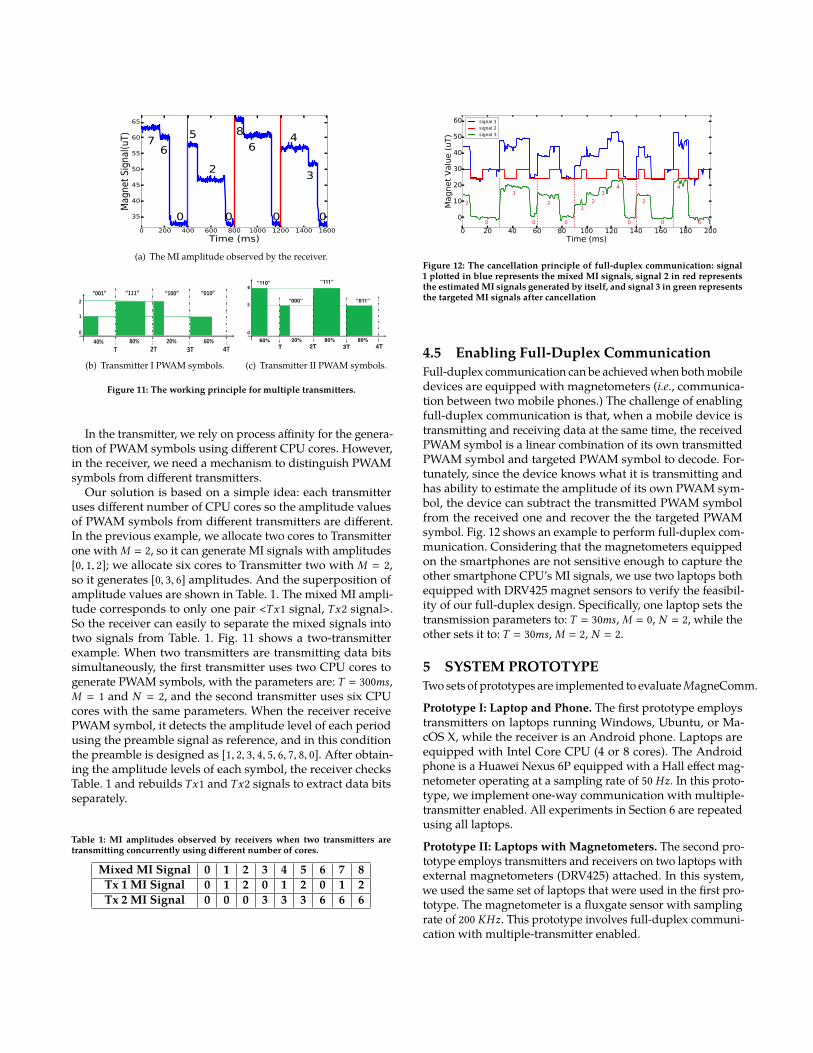
Figure 11: The working principle for multiple transmitters.
In the transmitter, we rely on process affinity for the genera-tion of PWAM symbols using different CPU cores. However,in the receiver, we need a mechanism to distinguish PWAMsymbols from different transmitters.
Our solution is based on a simple idea: each transmitteruses different number of CPU cores so the amplitude valuesof PWAM symbols from different transmitters are different.In the previous example, we allocate two cores to Transmitterone with M = 2, so it can generate MI signals with amplitudes[0, 1, 2]; we allocate six cores to Transmitter two with M = 2,so it generates [0, 3, 6] amplitudes. And the superposition ofamplitude values are shown in Table. 1. The mixed MI ampli-tude corresponds to only one pair <Tx1 signal, Tx2 signal>.So the receiver can easily to separate the mixed signals intotwo signals from Table. 1. Fig. 11 shows a two-transmitterexample. When two transmitters are transmitting data bitssimultaneously, the first transmitter uses two CPU cores togenerate PWAM symbols, with the parameters are: T = 300ms,M = 1 and N = 2, and the second transmitter uses six CPUcores with the same parameters. When the receiver receivePWAM symbol, it detects the amplitude level of each periodusing the preamble signal as reference, and in this conditionthe preamble is designed as [1, 2, 3, 4, 5, 6, 7, 8, 0]. After obtain-ing the amplitude levels of each symbol, the receiver checksTable. 1 and rebuilds Tx1 and Tx2 signals to extract data bitsseparately.
Table 1: MI amplitudes observed by receivers when two transmitters aretransmitting concurrently using different number of cores.
Mixed MI Signal 0 1 2 3 4 5 6 7 8Tx 1 MI Signal 0 1 2 0 1 2 0 1 2Tx 2 MI Signal 0 0 0 3 3 3 6 6 6
0 20 40 60 80 100 120 140 160 180 200
Time (ms)
0
10
20
30
40
50
60
Magnet
Valu
e (
uT)
2
0
3
0
2
0
1
2
3
4
0
2
0
4
0
signal 1
signal 2
signal 3
Figure 12: The cancellation principle of full-duplex communication: signal1 plotted in blue represents the mixed MI signals, signal 2 in red representsthe estimated MI signals generated by itself, and signal 3 in green representsthe targeted MI signals after cancellation
4.5 Enabling Full-Duplex CommunicationFull-duplex communication can be achieved when both mobiledevices are equipped with magnetometers (i.e., communica-tion between two mobile phones.) The challenge of enablingfull-duplex communication is that, when a mobile device istransmitting and receiving data at the same time, the receivedPWAM symbol is a linear combination of its own transmittedPWAM symbol and targeted PWAM symbol to decode. For-tunately, since the device knows what it is transmitting andhas ability to estimate the amplitude of its own PWAM sym-bol, the device can subtract the transmitted PWAM symbolfrom the received one and recover the the targeted PWAMsymbol. Fig. 12 shows an example to perform full-duplex com-munication. Considering that the magnetometers equippedon the smartphones are not sensitive enough to capture theother smartphone CPU’s MI signals, we use two laptops bothequipped with DRV425 magnet sensors to verify the feasibil-ity of our full-duplex design. Specifically, one laptop sets thetransmission parameters to: T = 30ms, M = 0, N = 2, while theother sets it to: T = 30ms, M = 2, N = 2.
5 SYSTEM PROTOTYPETwo sets of prototypes are implemented to evaluate MagneComm.
Prototype I: Laptop and Phone. The first prototype employstransmitters on laptops running Windows, Ubuntu, or Ma-cOS X, while the receiver is an Android phone. Laptops areequipped with Intel Core CPU (4 or 8 cores). The Androidphone is a Huawei Nexus 6P equipped with a Hall effect mag-netometer operating at a sampling rate of 50 Hz. In this proto-type, we implement one-way communication with multiple-transmitter enabled. All experiments in Section 6 are repeatedusing all laptops.
Prototype II: Laptops with Magnetometers. The second pro-totype employs transmitters and receivers on two laptops withexternal magnetometers (DRV425) attached. In this system,we used the same set of laptops that were used in the first pro-totype. The magnetometer is a fluxgate sensor with samplingrate of 200 KHz. This prototype involves full-duplex communi-cation with multiple-transmitter enabled.
-4
-2
0
2
4
6
8
10
12
0 2 4 6 8 10
SN
R (
dB
)
Distance (cm)
HP Envy 14
DELL Inspiron 15
ThinkPad T440
MacBookPro 13
Figure 13: SNR vs. distance using different models of laptops.
-2
0
2
4
6
8
10
12
14
16
0 1 2 3 4 5 6 7 8 9 10
SN
R (
dB
)
Distance (cm)
one core
two cores
three cores
four cores
Figure 14: SNR vs. number of working CPU cores.
0
20
40
60
80
100
0 50 100 150 200 250 300 350 400 450 500
De
tectio
n R
atio
(%
)
Preamble Length (ms)
Prototype2-clean backgroundPrototype2-watching live videoPrototype2-surfing websPrototype1-clean backgroundPrototype1-watching live videoPrototype1-surfing webs
Figure 15: Preamble detection accuracy under various preamble lengthswith M = 2.
0
20
40
60
80
100
120
[0,20)[20,40)
[40,60)[60,80)
[80,100)[100,120)
[120,140)
[140,160)
[160,180)
[180,400]
Thro
ughput (b
ps)
Background Noise Value
T=30,M=2,N=2
T=40,M=2,N=2
T=30,M=1,N=2
T=60,M=2,N=2
T=80,M=1,N=2
T=80,M=1,N=1
T=100,M=1,N=2
T=100,M=0,N=2
Figure 16: Throughput vs. levels of noise under various symbol lengthT .
6 EVALUATION6.1 Micro Benchmark
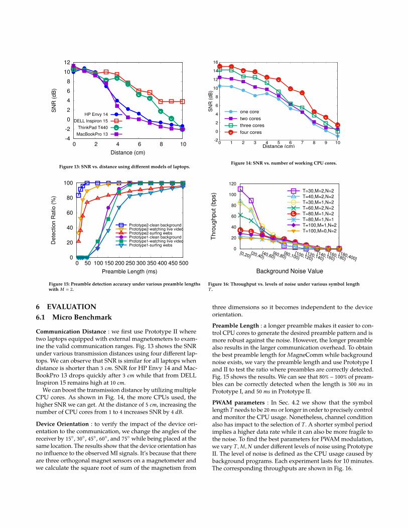
Communication Distance : we first use Prototype II wheretwo laptops equipped with external magnetometers to exam-ine the valid communication ranges. Fig. 13 shows the SNRunder various transmission distances using four different lap-tops. We can observe that SNR is similar for all laptops whendistance is shorter than 3 cm. SNR for HP Envy 14 and Mac-BookPro 13 drops quickly after 3 cm while that from DELLInspiron 15 remains high at 10 cm.
We can boost the transmission distance by utilizing multipleCPU cores. As shown in Fig. 14, the more CPUs used, thehigher SNR we can get. At the distance of 5 cm, increasing thenumber of CPU cores from 1 to 4 increases SNR by 4 dB.
Device Orientation : to verify the impact of the device ori-entation to the communication, we change the angles of thereceiver by 15◦, 30◦, 45◦, 60◦, and 75◦ while being placed at thesame location. The results show that the device orientation hasno influence to the observed MI signals. It’s because that thereare three orthogonal magnet sensors on a magnetometer andwe calculate the square root of sum of the magnetism from
three dimensions so it becomes independent to the deviceorientation.
Preamble Length : a longer preamble makes it easier to con-trol CPU cores to generate the desired preamble pattern and ismore robust against the noise. However, the longer preamblealso results in the larger communication overhead. To obtainthe best preamble length for MagneComm while backgroundnoise exists, we vary the preamble length and use Prototype Iand II to test the ratio where preambles are correctly detected.Fig. 15 shows the results. We can see that 80%− 100% of pream-bles can be correctly detected when the length is 300 ms inPrototype I, and 50ms in Prototype II.
PWAM parameters : In Sec. 4.2 we show that the symbollengthT needs to be 20ms or longer in order to precisely controland monitor the CPU usage. Nonetheless, channel conditionalso has impact to the selection of T . A shorter symbol periodimplies a higher data rate while it can also be more fragile tothe noise. To find the best parameters for PWAM modulation,we varyT ,M,N under different levels of noise using PrototypeII. The level of noise is defined as the CPU usage caused bybackground programs. Each experiment lasts for 10 minutes.The corresponding throughputs are shown in Fig. 16.
0
10
20
30
40
50
60
70
80
90
100
20ms30ms
50ms60ms
80ms100ms
300ms500ms
Perc
enta
ge V
alu
e (
%)
Symbol Length (ms)TPR FPR FNR
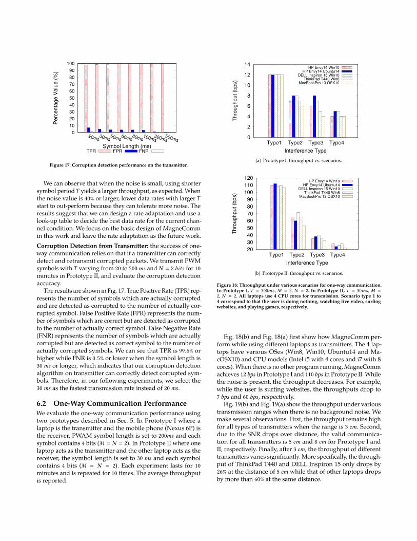
Figure 17: Corruption detection performance on the transmitter.
We can observe that when the noise is small, using shortersymbol periodT yields a larger throughput, as expected. Whenthe noise value is 40% or larger, lower data rates with larger Tstart to out-perform because they can tolerate more noise. Theresults suggest that we can design a rate adaptation and use alook-up table to decide the best data rate for the current chan-nel condition. We focus on the basic design of MagneCommin this work and leave the rate adaptation as the future work.Corruption Detection from Transmitter: the success of one-way communication relies on that if a transmitter can correctlydetect and retransmit corrupted packets. We transmit PWMsymbols withT varying from 20 to 500ms and N = 2 bits for 10minutes in Prototype II, and evaluate the corruption detectionaccuracy.
The results are shown in Fig. 17. True Positive Rate (TPR) rep-resents the number of symbols which are actually corruptedand are detected as corrupted to the number of actually cor-rupted symbol. False Positive Rate (FPR) represents the num-ber of symbols which are correct but are detected as corruptedto the number of actually correct symbol. False Negative Rate(FNR) represents the number of symbols which are actuallycorrupted but are detected as correct symbol to the number ofactually corrupted symbols. We can see that TPR is 99.6% orhigher while FNR is 0.5% or lower when the symbol length is30ms or longer, which indicates that our corruption detectionalgorithm on transmitter can correctly detect corrupted sym-bols. Therefore, in our following experiments, we select the30ms as the fastest transmission rate instead of 20ms.
6.2 One-Way Communication PerformanceWe evaluate the one-way communication performance usingtwo prototypes described in Sec. 5. In Prototype I where alaptop is the transmitter and the mobile phone (Nexus 6P) isthe receiver, PWAM symbol length is set to 200ms and eachsymbol contains 4 bits (M = N = 2). In Prototype II where onelaptop acts as the transmitter and the other laptop acts as thereceiver, the symbol length is set to 30 ms and each symbolcontains 4 bits (M = N = 2). Each experiment lasts for 10minutes and is repeated for 10 times. The average throughputis reported.
0
2
4
6
8
10
12
14
Type1 Type2 Type3 Type4
Thro
ughput (b
ps)
Interference Type
HP Envy14 Win10HP Envy14 Ubuntu14
DELL Inspiron 15 Win10ThinkPad T440 Win8
MacBookPro 13 OSX10
(a) Prototype I: throughput vs. scenarios.
20
30
40
50
60
70
80
90
100
110
120
Type1 Type2 Type3 Type4
Thro
ughput (b
ps)
Interference Type
HP Envy14 Win10HP Envy14 Ubuntu14
DELL Inspiron 15 Win10ThinkPad T440 Win8
MacBookPro 13 OSX10
(b) Prototype II: throughput vs. scenarios.
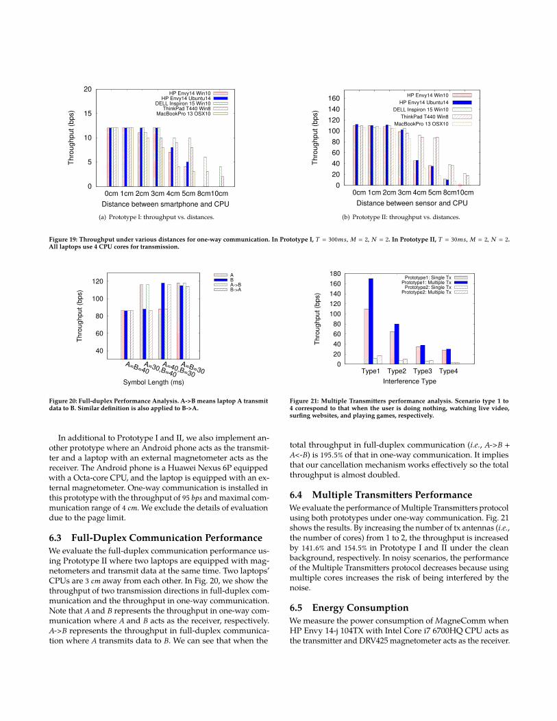
Figure 18: Throughput under various scenarios for one-way communication.In Prototype I, T = 300ms, M = 2, N = 2. In Prototype II, T = 30ms, M =2, N = 2. All laptops use 4 CPU cores for transmission. Scenario type 1 to4 correspond to that the user is doing nothing, watching live video, surfingwebsites, and playing games, respectively.
Fig. 18(b) and Fig. 18(a) first show how MagneComm per-form while using different laptops as transmitters. The 4 lap-tops have various OSes (Win8, Win10, Ubuntu14 and Ma-cOSX10) and CPU models (Intel i5 with 4 cores and i7 with 8cores). When there is no other program running, MagneCommachieves 12 bps in Prototype I and 110 bps in Prototype II. Whilethe noise is present, the throughput decreases. For example,while the user is surfing websites, the throughputs drop to7 bps and 60 bps, respectively.
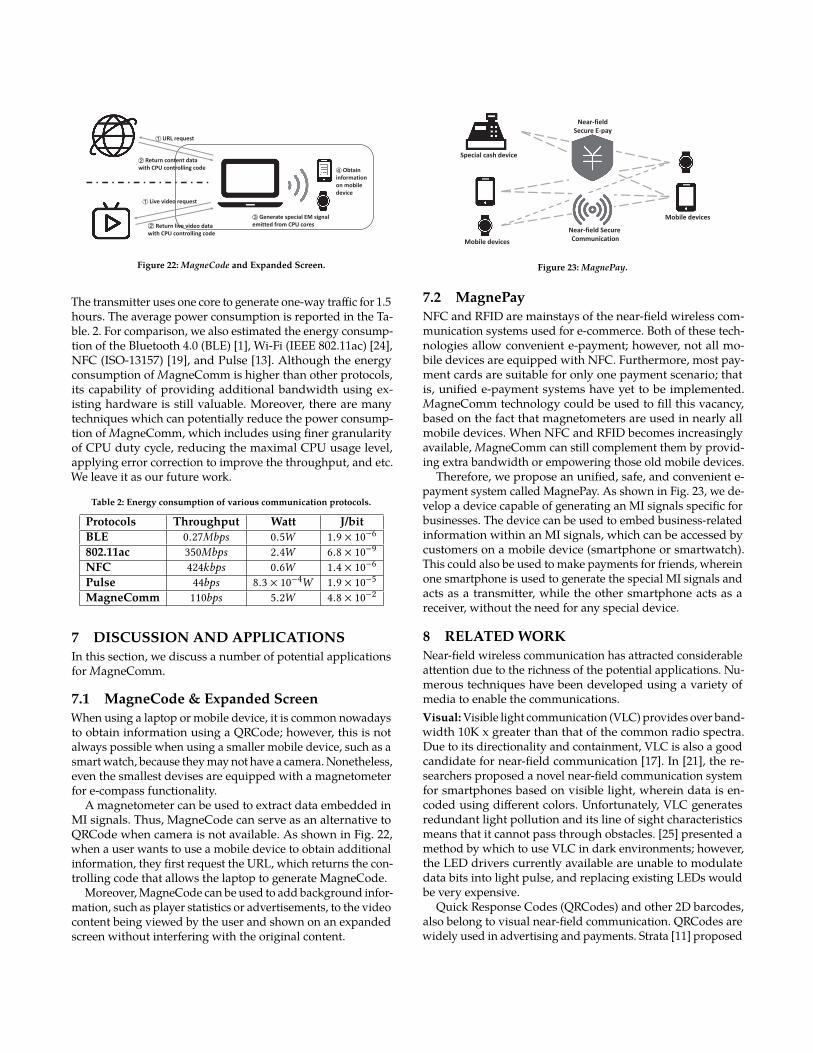
Fig. 19(b) and Fig. 19(a) show the throughput under varioustransmission ranges when there is no background noise. Wemake several observations. First, the throughput remains highfor all types of transmitters when the range is 3 cm. Second,due to the SNR drops over distance, the valid communica-tion for all transmitters is 5 cm and 8 cm for Prototype I andII, respectively. Finally, after 3 cm, the throughput of differenttransmitters varies significantly. More specifically, the through-put of ThinkPad T440 and DELL Inspiron 15 only drops by26% at the distance of 5 cm while that of other laptops dropsby more than 60% at the same distance.
0
5
10
15
20
0cm 1cm 2cm 3cm 4cm 5cm 8cm10cm
Thro
ughput (b
ps)
Distance between smartphone and CPU
HP Envy14 Win10HP Envy14 Ubuntu14
DELL Inspiron 15 Win10ThinkPad T440 Win8
MacBookPro 13 OSX10
(a) Prototype I: throughput vs. distances.
0
20
40
60
80
100
120
140
160
0cm 1cm 2cm 3cm 4cm 5cm 8cm10cm
Thro
ughput (b
ps)
Distance between sensor and CPU
HP Envy14 Win10
HP Envy14 Ubuntu14
DELL Inspiron 15 Win10
ThinkPad T440 Win8
MacBookPro 13 OSX10
(b) Prototype II: throughput vs. distances.
Figure 19: Throughput under various distances for one-way communication. In Prototype I, T = 300ms, M = 2, N = 2. In Prototype II, T = 30ms, M = 2, N = 2.All laptops use 4 CPU cores for transmission.
40
60
80
100
120
A=B=40A=30,B=40
A=40,B=30
A=B=30
Thro
ughput (b
ps)
Symbol Length (ms)
ABA->BB->A
Figure 20: Full-duplex Performance Analysis. A->B means laptop A transmitdata to B. Similar definition is also applied to B->A.
In additional to Prototype I and II, we also implement an-other prototype where an Android phone acts as the transmit-ter and a laptop with an external magnetometer acts as thereceiver. The Android phone is a Huawei Nexus 6P equippedwith a Octa-core CPU, and the laptop is equipped with an ex-ternal magnetometer. One-way communication is installed inthis prototype with the throughput of 95bps and maximal com-munication range of 4 cm. We exclude the details of evaluationdue to the page limit.
6.3 Full-Duplex Communication PerformanceWe evaluate the full-duplex communication performance us-ing Prototype II where two laptops are equipped with mag-netometers and transmit data at the same time. Two laptops’CPUs are 3 cm away from each other. In Fig. 20, we show thethroughput of two transmission directions in full-duplex com-munication and the throughput in one-way communication.Note that A and B represents the throughput in one-way com-munication where A and B acts as the receiver, respectively.A->B represents the throughput in full-duplex communica-tion where A transmits data to B. We can see that when the
0
20
40
60
80
100
120
140
160
180
Type1 Type2 Type3 Type4
Thro
ughput (b
ps)
Interference Type
Prototype1: Single TxPrototype1: Multiple Tx
Prototype2: Single TxPrototype2: Multiple Tx
Figure 21: Multiple Transmitters performance analysis. Scenario type 1 to4 correspond to that when the user is doing nothing, watching live video,surfing websites, and playing games, respectively.
total throughput in full-duplex communication (i.e., A->B +A<-B) is 195.5% of that in one-way communication. It impliesthat our cancellation mechanism works effectively so the totalthroughput is almost doubled.
6.4 Multiple Transmitters PerformanceWe evaluate the performance of Multiple Transmitters protocolusing both prototypes under one-way communication. Fig. 21shows the results. By increasing the number of tx antennas (i.e.,the number of cores) from 1 to 2, the throughput is increasedby 141.6% and 154.5% in Prototype I and II under the cleanbackground, respectively. In noisy scenarios, the performanceof the Multiple Transmitters protocol decreases because usingmultiple cores increases the risk of being interfered by thenoise.
6.5 Energy ConsumptionWe measure the power consumption of MagneComm whenHP Envy 14-j 104TX with Intel Core i7 6700HQ CPU acts asthe transmitter and DRV425 magnetometer acts as the receiver.
URL request
Return content data
with CPU controlling code
Generate special EM signal
emitted from CPU cores
Obtain
information
on mobile
device
Live video request
Return live video data
with CPU controlling code
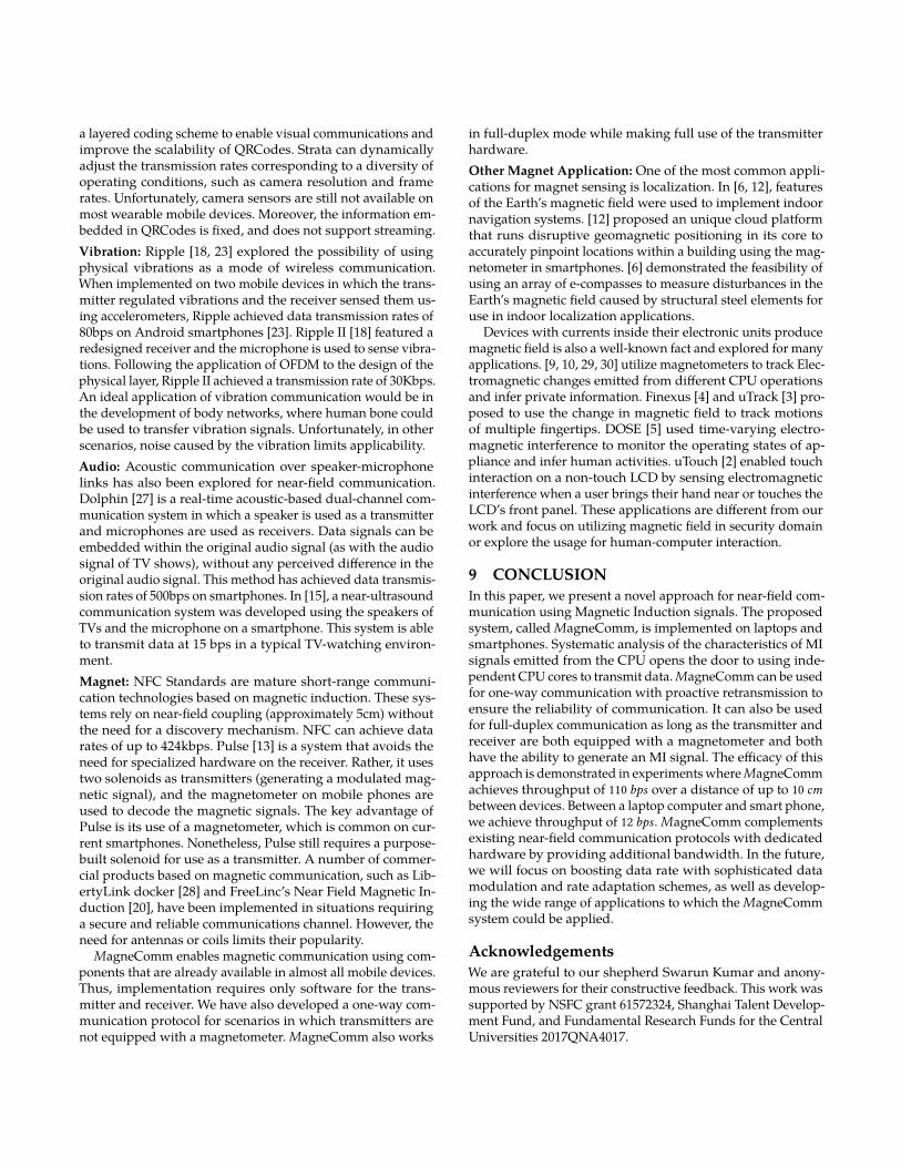
Figure 22: MagneCode and Expanded Screen.
The transmitter uses one core to generate one-way traffic for 1.5hours. The average power consumption is reported in the Ta-ble. 2. For comparison, we also estimated the energy consump-tion of the Bluetooth 4.0 (BLE) [1], Wi-Fi (IEEE 802.11ac) [24],NFC (ISO-13157) [19], and Pulse [13]. Although the energyconsumption of MagneComm is higher than other protocols,its capability of providing additional bandwidth using ex-isting hardware is still valuable. Moreover, there are manytechniques which can potentially reduce the power consump-tion of MagneComm, which includes using finer granularityof CPU duty cycle, reducing the maximal CPU usage level,applying error correction to improve the throughput, and etc.We leave it as our future work.
Table 2: Energy consumption of various communication protocols.
7 DISCUSSION AND APPLICATIONSIn this section, we discuss a number of potential applicationsfor MagneComm.
7.1 MagneCode & Expanded ScreenWhen using a laptop or mobile device, it is common nowadaysto obtain information using a QRCode; however, this is notalways possible when using a smaller mobile device, such as asmart watch, because they may not have a camera. Nonetheless,even the smallest devises are equipped with a magnetometerfor e-compass functionality.
A magnetometer can be used to extract data embedded inMI signals. Thus, MagneCode can serve as an alternative toQRCode when camera is not available. As shown in Fig. 22,when a user wants to use a mobile device to obtain additionalinformation, they first request the URL, which returns the con-trolling code that allows the laptop to generate MagneCode.
Moreover, MagneCode can be used to add background infor-mation, such as player statistics or advertisements, to the videocontent being viewed by the user and shown on an expandedscreen without interfering with the original content.
Near-field Secure
Communication
Special cash device
Mobile devices
Mobile devices
Near-field
Secure E-pay
Figure 23: MagnePay.
7.2 MagnePayNFC and RFID are mainstays of the near-field wireless com-munication systems used for e-commerce. Both of these tech-nologies allow convenient e-payment; however, not all mo-bile devices are equipped with NFC. Furthermore, most pay-ment cards are suitable for only one payment scenario; thatis, unified e-payment systems have yet to be implemented.MagneComm technology could be used to fill this vacancy,based on the fact that magnetometers are used in nearly allmobile devices. When NFC and RFID becomes increasinglyavailable, MagneComm can still complement them by provid-ing extra bandwidth or empowering those old mobile devices.
Therefore, we propose an unified, safe, and convenient e-payment system called MagnePay. As shown in Fig. 23, we de-velop a device capable of generating an MI signals specific forbusinesses. The device can be used to embed business-relatedinformation within an MI signals, which can be accessed bycustomers on a mobile device (smartphone or smartwatch).This could also be used to make payments for friends, whereinone smartphone is used to generate the special MI signals andacts as a transmitter, while the other smartphone acts as areceiver, without the need for any special device.
8 RELATED WORKNear-field wireless communication has attracted considerableattention due to the richness of the potential applications. Nu-merous techniques have been developed using a variety ofmedia to enable the communications.Visual: Visible light communication (VLC) provides over band-width 10K x greater than that of the common radio spectra.Due to its directionality and containment, VLC is also a goodcandidate for near-field communication [17]. In [21], the re-searchers proposed a novel near-field communication systemfor smartphones based on visible light, wherein data is en-coded using different colors. Unfortunately, VLC generatesredundant light pollution and its line of sight characteristicsmeans that it cannot pass through obstacles. [25] presented amethod by which to use VLC in dark environments; however,the LED drivers currently available are unable to modulatedata bits into light pulse, and replacing existing LEDs wouldbe very expensive.
Quick Response Codes (QRCodes) and other 2D barcodes,also belong to visual near-field communication. QRCodes arewidely used in advertising and payments. Strata [11] proposed
a layered coding scheme to enable visual communications andimprove the scalability of QRCodes. Strata can dynamicallyadjust the transmission rates corresponding to a diversity ofoperating conditions, such as camera resolution and framerates. Unfortunately, camera sensors are still not available onmost wearable mobile devices. Moreover, the information em-bedded in QRCodes is fixed, and does not support streaming.Vibration: Ripple [18, 23] explored the possibility of usingphysical vibrations as a mode of wireless communication.When implemented on two mobile devices in which the trans-mitter regulated vibrations and the receiver sensed them us-ing accelerometers, Ripple achieved data transmission rates of80bps on Android smartphones [23]. Ripple II [18] featured aredesigned receiver and the microphone is used to sense vibra-tions. Following the application of OFDM to the design of thephysical layer, Ripple II achieved a transmission rate of 30Kbps.An ideal application of vibration communication would be inthe development of body networks, where human bone couldbe used to transfer vibration signals. Unfortunately, in otherscenarios, noise caused by the vibration limits applicability.Audio: Acoustic communication over speaker-microphonelinks has also been explored for near-field communication.Dolphin [27] is a real-time acoustic-based dual-channel com-munication system in which a speaker is used as a transmitterand microphones are used as receivers. Data signals can beembedded within the original audio signal (as with the audiosignal of TV shows), without any perceived difference in theoriginal audio signal. This method has achieved data transmis-sion rates of 500bps on smartphones. In [15], a near-ultrasoundcommunication system was developed using the speakers ofTVs and the microphone on a smartphone. This system is ableto transmit data at 15 bps in a typical TV-watching environ-ment.Magnet: NFC Standards are mature short-range communi-cation technologies based on magnetic induction. These sys-tems rely on near-field coupling (approximately 5cm) withoutthe need for a discovery mechanism. NFC can achieve datarates of up to 424kbps. Pulse [13] is a system that avoids theneed for specialized hardware on the receiver. Rather, it usestwo solenoids as transmitters (generating a modulated mag-netic signal), and the magnetometer on mobile phones areused to decode the magnetic signals. The key advantage ofPulse is its use of a magnetometer, which is common on cur-rent smartphones. Nonetheless, Pulse still requires a purpose-built solenoid for use as a transmitter. A number of commer-cial products based on magnetic communication, such as Lib-ertyLink docker [28] and FreeLinc’s Near Field Magnetic In-duction [20], have been implemented in situations requiringa secure and reliable communications channel. However, theneed for antennas or coils limits their popularity.
MagneComm enables magnetic communication using com-ponents that are already available in almost all mobile devices.Thus, implementation requires only software for the trans-mitter and receiver. We have also developed a one-way com-munication protocol for scenarios in which transmitters arenot equipped with a magnetometer. MagneComm also works
in full-duplex mode while making full use of the transmitterhardware.Other Magnet Application: One of the most common appli-cations for magnet sensing is localization. In [6, 12], featuresof the Earth’s magnetic field were used to implement indoornavigation systems. [12] proposed an unique cloud platformthat runs disruptive geomagnetic positioning in its core toaccurately pinpoint locations within a building using the mag-netometer in smartphones. [6] demonstrated the feasibility ofusing an array of e-compasses to measure disturbances in theEarth’s magnetic field caused by structural steel elements foruse in indoor localization applications.
Devices with currents inside their electronic units producemagnetic field is also a well-known fact and explored for manyapplications. [9, 10, 29, 30] utilize magnetometers to track Elec-tromagnetic changes emitted from different CPU operationsand infer private information. Finexus [4] and uTrack [3] pro-posed to use the change in magnetic field to track motionsof multiple fingertips. DOSE [5] used time-varying electro-magnetic interference to monitor the operating states of ap-pliance and infer human activities. uTouch [2] enabled touchinteraction on a non-touch LCD by sensing electromagneticinterference when a user brings their hand near or touches theLCD’s front panel. These applications are different from ourwork and focus on utilizing magnetic field in security domainor explore the usage for human-computer interaction.
9 CONCLUSIONIn this paper, we present a novel approach for near-field com-munication using Magnetic Induction signals. The proposedsystem, called MagneComm, is implemented on laptops andsmartphones. Systematic analysis of the characteristics of MIsignals emitted from the CPU opens the door to using inde-pendent CPU cores to transmit data. MagneComm can be usedfor one-way communication with proactive retransmission toensure the reliability of communication. It can also be usedfor full-duplex communication as long as the transmitter andreceiver are both equipped with a magnetometer and bothhave the ability to generate an MI signal. The efficacy of thisapproach is demonstrated in experiments where MagneCommachieves throughput of 110 bps over a distance of up to 10 cmbetween devices. Between a laptop computer and smart phone,we achieve throughput of 12 bps. MagneComm complementsexisting near-field communication protocols with dedicatedhardware by providing additional bandwidth. In the future,we will focus on boosting data rate with sophisticated datamodulation and rate adaptation schemes, as well as develop-ing the wide range of applications to which the MagneCommsystem could be applied.
AcknowledgementsWe are grateful to our shepherd Swarun Kumar and anony-mous reviewers for their constructive feedback. This work wassupported by NSFC grant 61572324, Shanghai Talent Develop-ment Fund, and Fundamental Research Funds for the CentralUniversities 2017QNA4017.
REFERENCES[1] Bluetooth Low Energy 2017. Bluetooth 4.0 BLE. (2017).
https://en.m.wikipedia.org/wiki/Bluetooth_Low_Energy.[2] K. Chen, G. A. Cohn, S. Gupta, and S. N. Patel. 2013. uTouch: Sensing Touch
Gestures on Unmodified LCDs. In Proceedings of the SIGCHI Conference onHuman Factors in Computing Systems (CHI ’13). ACM, New York, NY, USA,2581–2584. https://doi.org/10.1145/2470654.2481356
[3] K. Chen, K. Lyons, S. White, and S. Patel. 2013. uTrack: 3D Input UsingTwo Magnetic Sensors. In Proceedings of the 26th Annual ACM Symposium onUser Interface Software and Technology (UIST ’13). ACM, New York, NY, USA,237–244. https://doi.org/10.1145/2501988.2502035
[4] K. Chen, S. N. Patel, and S. Keller. 2016. Finexus: Tracking Precise Motionsof Multiple Fingertips Using Magnetic Sensing. In Proceedings of the 2016CHI Conference on Human Factors in Computing Systems (CHI ’16). ACM, NewYork, NY, USA, 1504–1514. https://doi.org/10.1145/2858036.2858125
[5] K. Y. Chen, S. Gupta, E. C. Larson, and S. Patel. 2015. DOSE: Detectinguser-driven operating states of electronic devices from a single sensingpoint. In 2015 IEEE International Conference on Pervasive Computing andCommunications (PerCom). 46–54. https://doi.org/10.1109/PERCOM.2015.7146508
[6] J. Chung, M. Donahoe, C. Schmandt, I. Kim, P. Razavai, and M. Wiseman.2011. Indoor Location Sensing Using Geo-magnetism. In Proceedings ofthe 9th International Conference on Mobile Systems, Applications, and Services(MobiSys ’11). ACM, 141–154.
[7] DRV425 2016. Integrated Fluxgate Magnetic Sensor IC for Open-LoopApplications. (2016). https://www.ti.com/product/DRV425.
[8] D. Genkin, L. Pachmanov, I. Pipman, and E. Tromer. 2015. Stealing Keysfrom PCs Using a Radio: Cheap Electromagnetic Attacks on WindowedExponentiation.. In CHES (Lecture Notes in Computer Science), Vol. 9293.Springer, 207–228.
[9] D. Genkin, I. Pipman, and E. Tromer. 2015. Get your hands off my laptop:physical side-channel key-extraction attacks on PCs - Extended version. J.Cryptographic Engineering 5, 2 (2015), 95–112. http://dblp.uni-trier.de/db/journals/jce/jce5.html#GenkinPT15
[10] W. Gu, Z. Yang, L. Shangguan, X. Ji, and Y. Zhao. 2014. ToAuth: TowardsAutomatic Near Field Authentication for Smartphones. In 2014 IEEE 13thInternational Conference on Trust, Security and Privacy in Computing and Com-munications. 229–236. https://doi.org/10.1109/TrustCom.2014.34
[11] W. Hu, J. Mao, Z. Huang, Y. Xue, J. She, K. Bian, and G. Shen. 2014. Strata:Layered Coding for Scalable Visual Communication. In Proceedings of the20th Annual International Conference on Mobile Computing and Networking(MobiCom ’14). ACM, 79–90.
[12] IndoorAtlas 2017. IndoorAtlas. (2017). http://www.indooratlas.com.[13] W. Jiang, D. Ferreira, J. Ylioja, J. Goncalves, and V. Kostakos. 2014. Pulse:
Low Bitrate Wireless Magnetic Communication for Smartphones. In Proceed-ings of the 2014 ACM International Joint Conference on Pervasive and UbiquitousComputing (UbiComp ’14). ACM, 261–265.
[14] H. Balakrishnan K. Jamieson. 2007. PPR: partial packet recovery for wirelessnetworks. In ACM SIGCOMM Computer Communication Review. ACM, 409–429.
[15] S. Ka, T. H. Kim, J. Y. Ha, S. H. Lim, S. C. Shin, J. W. Choi, C. Kwak, andS. Choi. 2016. Near-ultrasound Communication for TV’s 2Nd Screen Ser-vices. In Proceedings of the 22Nd Annual International Conference on MobileComputing and Networking (MobiCom ’16). ACM, 42–54.
[16] Lorentz force 2017. Lorentz force. (2017).https://en.wikipedia.org/wiki/Lorentz_force.
[17] M. Kavehrad N. Chi, H. Haas and T.D. Little. 2015. Visible light commu-nications: demands factors, benefits and opportunities. In IEEE WirelessCommunications.
[18] R.R. Choudhury N. Roy. 2016. Ripple II: Faster Communication throughPhysical Vibration. In 13th USENIX Symposium on Networked Systems Designand Implementation (NSDI 15). USENIX Association.
[19] NFC ISO 13157 2017. NFC ISO 13157. (2017).https://en.wikipedia.org/wiki/Near_field_communication.
[20] NFMI 2017. NFMI by FreeLinc. (2017).http://www.freelinc.com/technology.
[21] J. Niu, W. Song, C. Liu, L. Shu, and C. Chen. 2014. NECAS: Near fieldcommunication system for smartphones based on visible light. In IEEEWireless Communications and Networking Conference, WCNC 2014, Istanbul,Turkey, April 6-9, 2014. 2426–2431.
[22] Luigi Rizzo. 1997. Effective erasure codes for reliable computer commu-nication protocols. In ACM SIGCOMM Computer Communication Review.ACM, 24–36.
[23] N. Roy, M. Gowda, and R. R. Choudhury. 2015. Ripple: Communicatingthrough Physical Vibration. In 12th USENIX Symposium on Networked Sys-tems Design and Implementation (NSDI 15). USENIX Association, Oakland,CA, 265–278.
[24] P. P. Inamdar S. K. Saha, P. Deshpande. 2015. Power-throughput tradeoffs of802.11n/ac in smartphones. In IEEE Conference on Computer Communications(INFOCOM). IEEE.
[25] K. Wright T. Zhao and Z. Xia. 2016. The DarkLight Rises: Visible LightCommunication in the Dark. In In Proc. of MobiCom.
[26] TMurgent Technologies. 2003. White Paper: Processor Affinity. TMurgentTechnologies.
[27] Q. Wang, K. Ren, M. Zhou, T. Lei, D. Koutsonikolas, and L. Su. 2016. Mes-sages Behind the Sound: Real-time Hidden Acoustic Signal Capture withSmartphones. In Proceedings of the 22Nd Annual International Conference onMobile Computing and Networking (MobiCom ’16). ACM, 29–41.
[28] Dan Wolfson. 2003. The LibertyLink Docker Wireless Headset. ComputingUnplugged (December 2003).
[29] A. Zajic and M. Prvulovic. 2014. Experimental Demonstration of Electro-magnetic Information Leakage From Modern Processor-Memory Systems.IEEE Transactions on Electromagnetic Compatibility 56, 4 (Aug 2014), 885–893.https://doi.org/10.1109/TEMC.2014.2300139
[30] Z. Zhu, H. Pan, Y. Chen, X. Ji, F. Zhang, and C. You. 2016. MagAttack:Remote App Sensing with Your Phone. In Proceedings of the 2016 ACMInternational Joint Conference on Pervasive and Ubiquitous Computing: Adjunct(UbiComp ’16). ACM, New York, NY, USA, 241–244. https://doi.org/10.1145/2968219.2971404


![@sjtu.edu.cn arXiv:1811.08264v4 [cs.CV] 11 Jun 2019](https://static.documents.pub/doc/80x56/61cd55b770870a751848ca95/sjtueducn-arxiv181108264v4-cscv-11-jun-2019.jpg)


