MAGNETIC CIRCUITS The study of magnetic circuits is important in the study of energy systems since the operation of key components such as transformers and rotating machines (DC machines, induction machines, synchronous machines) can be characterized efficiently using magnetic circuits. Magnetic circuits, which characterize the behavior of the magnetic fields within a given device or set of devices, can be analyzed using the circuit analysis techniques defined for electric circuits. The quantities of interest in a magnetic circuit are the vector magnetic field H (A/m), the vector magnetic flux density B (T = Wb/m 2 ) and the total magnetic flux R m (Wb). The vector magnetic field and vector magnetic flux density are related by where : is defined as the total permeability (H/m), : r is the relative permeability (unitless), and : o = 4B ×10 !7 H/m is the permeability of free space. The total magnetic flux through a given surface S is found by integrating the normal component of the magnetic flux density over the surface where the vector differential surface is given by ds = a n ds and where a n defines a unit vector normal to the surface S. The relative permeability is a measure of how much magnetization occurs within the material. There is no magnetization in free space (vacuum) and negligible magnetization in common conductors such as copper and aluminum. These materials are characterized by a relative permeability of unity (: r =1). There are certain magnetic materials with very high relative permeabilities that are commonly found in components of energy systems. These materials (iron, steel, nickel, cobalt, etc.), designated as ferromagnetic materials, are characterized by significant magnetization. Ferromagnetic materials can be thought of as efficient conductors of
Transcript
MAGNETIC CIRCUITS
The study of magnetic circuits is important in the study of energysystems since the operation of key components such as transformers androtating machines (DC machines, induction machines, synchronousmachines) can be characterized efficiently using magnetic circuits.Magnetic circuits, which characterize the behavior of the magnetic fieldswithin a given device or set of devices, can be analyzed using the circuitanalysis techniques defined for electric circuits.
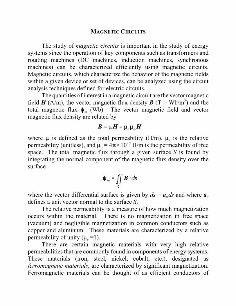
The quantities of interest in a magnetic circuit are the vector magneticfield H (A/m), the vector magnetic flux density B (T = Wb/m2) and thetotal magnetic flux Rm (Wb). The vector magnetic field and vectormagnetic flux density are related by
where : is defined as the total permeability (H/m), :r is the relativepermeability (unitless), and :o = 4B×10!7 H/m is the permeability of freespace. The total magnetic flux through a given surface S is found byintegrating the normal component of the magnetic flux density over thesurface
where the vector differential surface is given by ds = ands and where andefines a unit vector normal to the surface S.
The relative permeability is a measure of how much magnetizationoccurs within the material. There is no magnetization in free space(vacuum) and negligible magnetization in common conductors such ascopper and aluminum. These materials are characterized by a relativepermeability of unity (:r =1).
There are certain magnetic materials with very high relativepermeabilities that are commonly found in components of energy systems.These materials (iron, steel, nickel, cobalt, etc.), designated asferromagnetic materials, are characterized by significant magnetization.Ferromagnetic materials can be thought of as efficient conductors of
magnetic fields. The relative permeabilities of ferromagnetic materials canrange from a few hundred to a few thousand. Ferromagnetic materials arehighly nonlinear. That is, the relative permeability is not a constant, butdepends on the magnitude of the magnetic field for a given problem. Thus,the relationship between the magnetic field and the magnetic flux densityin a nonlinear medium can be written as
The characteristics of ferromagnetic materials are typically presentedusing the B-H curve, a plot of the magnetic flux density B in the materialdue to a given applied magnetic field H. The B-H curve shows the initialmagnetization curve along with a curve known as a hysteresis loop.
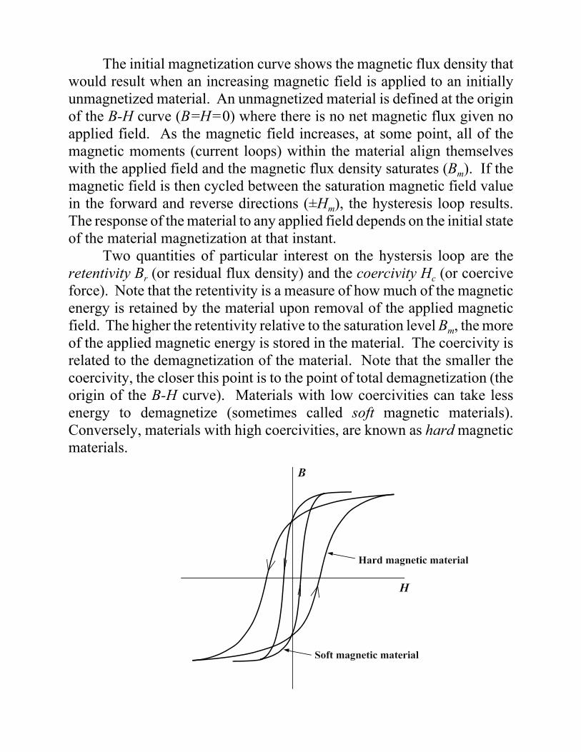
The initial magnetization curve shows the magnetic flux density thatwould result when an increasing magnetic field is applied to an initiallyunmagnetized material. An unmagnetized material is defined at the originof the B-H curve (B=H=0) where there is no net magnetic flux given noapplied field. As the magnetic field increases, at some point, all of themagnetic moments (current loops) within the material align themselveswith the applied field and the magnetic flux density saturates (Bm). If themagnetic field is then cycled between the saturation magnetic field valuein the forward and reverse directions (±Hm), the hysteresis loop results.The response of the material to any applied field depends on the initial stateof the material magnetization at that instant.
Two quantities of particular interest on the hystersis loop are theretentivity Br (or residual flux density) and the coercivity Hc (or coerciveforce). Note that the retentivity is a measure of how much of the magneticenergy is retained by the material upon removal of the applied magneticfield. The higher the retentivity relative to the saturation level Bm, the moreof the applied magnetic energy is stored in the material. The coercivity isrelated to the demagnetization of the material. Note that the smaller thecoercivity, the closer this point is to the point of total demagnetization (theorigin of the B-H curve). Materials with low coercivities can take lessenergy to demagnetize (sometimes called soft magnetic materials).Conversely, materials with high coercivities, are known as hard magneticmaterials.
CURRENT AND MAGNETIC FIELD
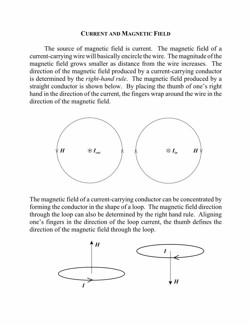
The source of magnetic field is current. The magnetic field of acurrent-carrying wire will basically encircle the wire. The magnitude of themagnetic field grows smaller as distance from the wire increases. Thedirection of the magnetic field produced by a current-carrying conductoris determined by the right-hand rule. The magnetic field produced by astraight conductor is shown below. By placing the thumb of one’s righthand in the direction of the current, the fingers wrap around the wire in thedirection of the magnetic field.
The magnetic field of a current-carrying conductor can be concentrated byforming the conductor in the shape of a loop. The magnetic field directionthrough the loop can also be determined by the right hand rule. Aligningone’s fingers in the direction of the loop current, the thumb defines thedirection of the magnetic field through the loop.
The magnetic field of a current-carrying conductor can be furtherconcentrated by forming multiple turn loops (coils). This, in effect,increases the magnetic field by a multiplication factor equal to the numberof turns N.
MAGNETIC FLUX DENSITY AND TOTAL MAGNETIC FLUX
The total magnetic flux passing through a given surface S is found byintegrating the normal component of the magnetic flux density over thesurface.
where ds = an dsan ! unit vector normal to the surface Sds ! differential surface element on S
For the special case of a uniform magnetic flux density over thesurface S, the integral for the total magnetic flux reduces to
where A is the total surface area of S. Thus, in regions of uniform magneticflux density, the magnetic flux density is equal to the total magnetic flux Rmdivided by the total area A.
The magnetic flux density is commonly assumed to be uniform withinferromagnetic materials.
AMPERE’S LAW
Ampere’s law is the Maxwell equation that relates the magnetic field(flux) to the source of the magnetic field (current).
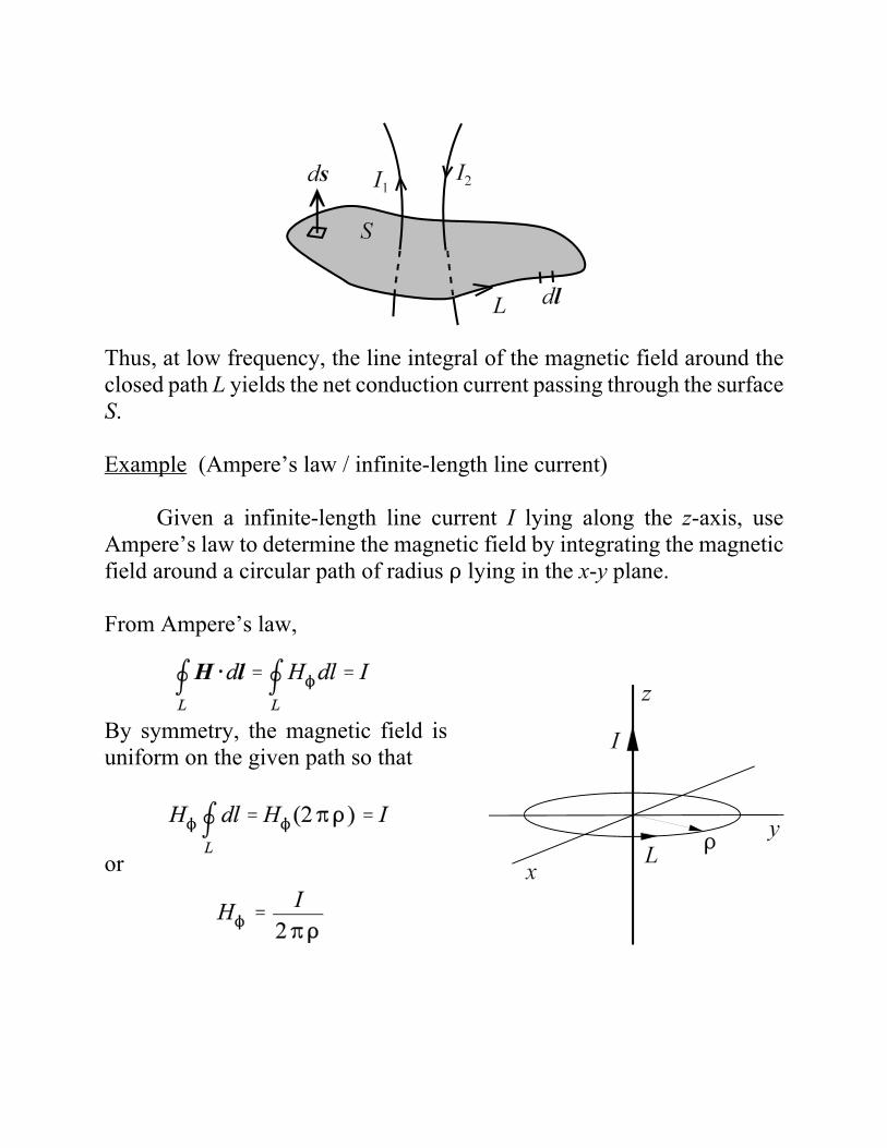
Ampere’s Law - The line integral of the magnetic field around aclosed path equals the net current enclosed (conduction plusdisplacement current).
Note that the current direction is implied by the direction of the path L andthe normal to the surface S according to the right hand rule. Thedisplacement current is negligible at the commonly-used power frequenciesof energy systems. Under this assumption, Ampere’s law reduces to
Thus, at low frequency, the line integral of the magnetic field around theclosed path L yields the net conduction current passing through the surfaceS.
Example (Ampere’s law / infinite-length line current)
Given a infinite-length line current I lying along the z-axis, useAmpere’s law to determine the magnetic field by integrating the magneticfield around a circular path of radius D lying in the x-y plane.
From Ampere’s law,
By symmetry, the magnetic field isuniform on the given path so that
or
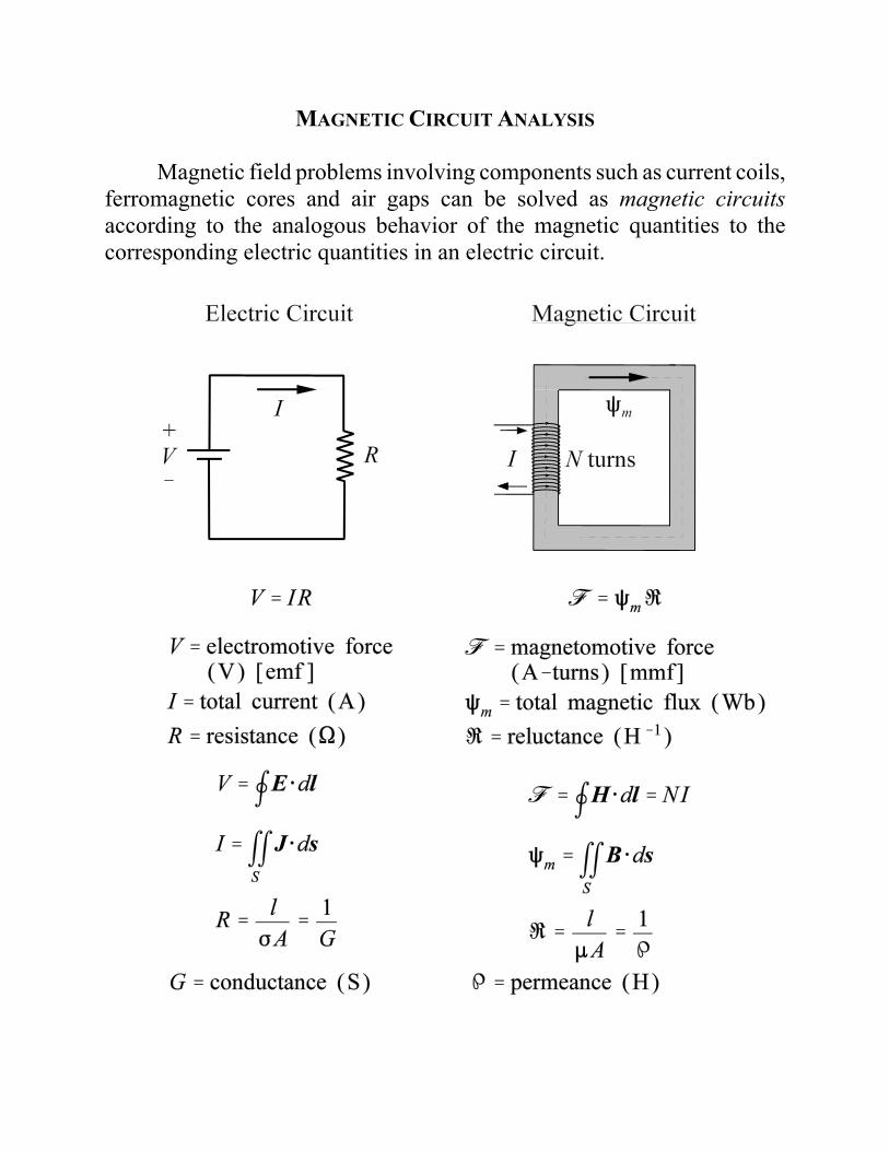
MAGNETIC CIRCUIT ANALYSIS
Magnetic field problems involving components such as current coils,ferromagnetic cores and air gaps can be solved as magnetic circuitsaccording to the analogous behavior of the magnetic quantities to thecorresponding electric quantities in an electric circuit.
Given that reluctance in a magnetic circuit is analogous to resistancein an electric circuit, and permeability in a magnetic circuit is analogous toconductivity in an electric circuit, we may interpret the permeability of amedium as a measure of the resistance of the material to magnetic flux.Just as current in an electric circuit follows the path of least resistance, themagnetic flux in a magnetic circuit follows the path of least reluctance.
The ferromagnetic cores of transformers form closed loops (no airgaps). The ferromagnetic cores of rotating machinery must have air gapsin the resulting magnetic circuit. These air gaps typically represent a largeportion of the overall magnetic circuit reluctance. In some cases ofmagnetic circuits with air gaps, we neglect the reluctance of theferromagnetic core. Assuming the reluctance of the ferromagnetic core iszero is equivalent to assuming that the relative permeability of the core isinfinite.
This is analogous to neglecting the resistance of conductors with very highconductivity in electric circuits.
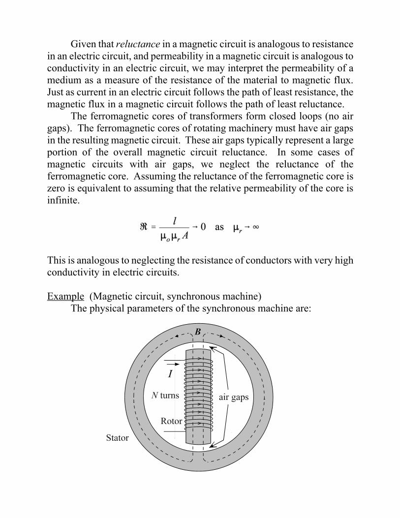
Example (Magnetic circuit, synchronous machine)The physical parameters of the synchronous machine are:
Air gap length g = 1cmI = 10 AN = 1000 turnsRotor pole face area Ar = 0.2 m2
Assume that the rotor and the stator of the synchronous machine havenegligible reluctance (infinite permeability) and neglect fringing.
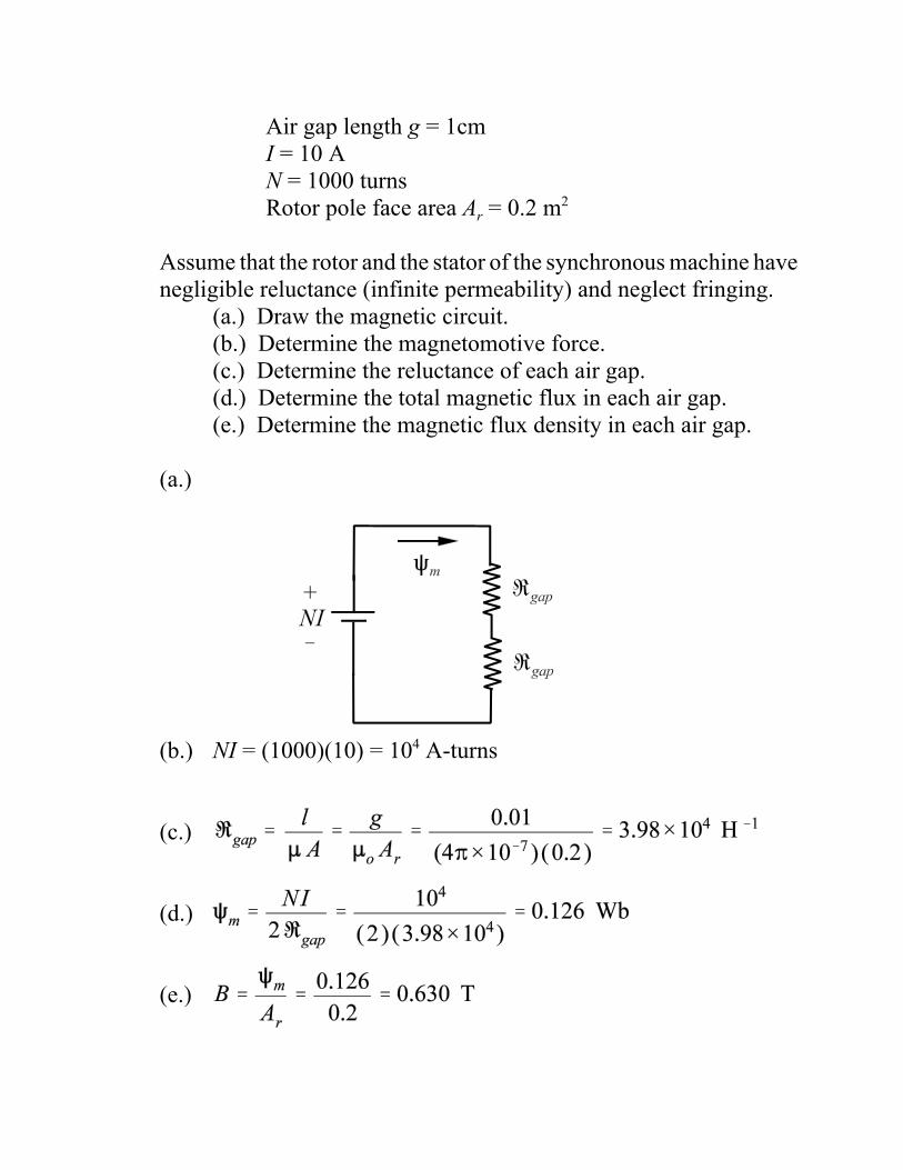
(a.) Draw the magnetic circuit. (b.) Determine the magnetomotive force.(c.) Determine the reluctance of each air gap.(d.) Determine the total magnetic flux in each air gap.(e.) Determine the magnetic flux density in each air gap.
(a.)
(b.) NI = (1000)(10) = 104 A-turns
(c.)
(d.)
(e.)
Example (Series/parallel magnetic circuits)
Determine the magnetic field in the air gap of the magneticcircuit shown below. The cross sectional area of all branches is 10cm2 and :r=50.
The equivalent electric circuit is
The reluctance components for the magnetic circuit are
The equivalent circuit can be reduced to
SOLENOIDS, TOROIDS, AND OTHER UNIFORM CORES
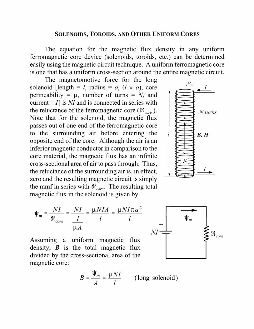
The equation for the magnetic flux density in any uniformferromagnetic core device (solenoids, toroids, etc.) can be determinedeasily using the magnetic circuit technique. A uniform ferromagnetic coreis one that has a uniform cross-section around the entire magnetic circuit.
The magnetomotive force for the longsolenoid [length = l, radius = a, (l o a), corepermeability = :, number of turns = N, andcurrent = I] is NI and is connected in series withthe reluctance of the ferromagnetic core (Ucore ).Note that for the solenoid, the magnetic fluxpasses out of one end of the ferromagnetic coreto the surrounding air before entering theopposite end of the core. Although the air is aninferior magnetic conductor in comparison to thecore material, the magnetic flux has an infinitecross-sectional area of air to pass through. Thus,the reluctance of the surrounding air is, in effect,zero and the resulting magnetic circuit is simplythe mmf in series with Ucore. The resulting totalmagnetic flux in the solenoid is given by
Assuming a uniform magnetic fluxdensity, B is the total magnetic fluxdivided by the cross-sectional area of themagnetic core:
The assumption that the solenoid is “long” is necessary in order toassume that the magnetic flux density is approximately uniform over theentire volume inside the solenoid. The magnetic flux density actuallygrows smaller near the ends of the long solenoid, but if l o a, then thefringing effects near the end of the solenoid become negligible.
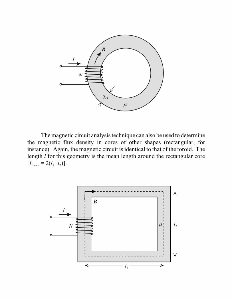
If the long solenoid is bent into the shape of a circle, a toroid isformed. The toroid [mean length = l = 2BDo (Do = toroid mean radius), corecross-sectional area = A, corepermeability = :, number ofturns = N, and current = I] hasthe advantage that themagnetic field is containedtotally within magnetic core,unlike the solenoid. Themagnetic circuit for the toroidis identical to that of thesolenoid. The only differenceis that the length l used in thereluctance calculation is themean length of the toroid ( l =2BDo). Inserting the toroidmean length into the solenoidequations for Rm and B gives
If the core of the toroid is a ferromagnetic material with a largerelative permeability, the turns of the current coil can be placed at anylocation on the toroid and the previous equation is still valid. This is truesince the magnetic reluctance of a ferromagnetic core with a large :r is somuch smaller than that of the surrounding air, that all of the magnetic fluxtends to stay within the core, irregardless of how the coils are arranged.
The magnetic circuit analysis technique can also be used to determinethe magnetic flux density in cores of other shapes (rectangular, forinstance). Again, the magnetic circuit is identical to that of the toroid. Thelength l for this geometry is the mean length around the rectangular core[Lcore = 2(l1+l2)].
The total magnetic flux and magnetic flux density inside therectangular core are
As previously shown, the magnetic circuit technique can be appliedto more complicated (nonuniform) core geometries. However, innonuniform cores (multiple flux paths, irregular cross-sections, etc.),multiple equations are necessary to define different values of total magneticflux and magnetic flux density at different locations in the core.
The total magnetic flux equation for the general uniform core deviceis useful in determining the self-inductance.
The self-inductance is defined as the ratio of magnetic flux linkage (7) tocurrent (I).
For any uniform core device, the flux linkage is equal to the number ofturns (N) times the total magnetic flux (Rm). The inductance of the uniformcore device becomes
Applying the inductance equation to the three previous uniform coreexamples gives
The determination of the self-inductance for nonuniform core devices,such as magnetic circuits with air gaps, follows according to the equation
where Utotal is the total reluctance seen by the mmf in the equivalentmagnetic circuit. Inserting this equation into the self-inductance equationyields
LOSSES IN MAGNETIC CIRCUITS
There are two major sources for energy loss in magnetic circuits.These are:
(1) Hysteresis loss(2) Eddy current loss
Hysteresis Loss
Under AC excitation, the ferromagnetic core undergoes continualhysteresis. There is energy lost in each hysteresis cycle. The energy lossin the ferromagnetic core is in the form of heat caused by the movement ofthe magnetic dipoles as the excitation field oscillates back and forth. It canbe shown that the hysteresis loss (Ph) can be written as
where Kh and n are empirically determined constants dependent on thecharacteristics of the core material and the core volume. Note that thehysteresis loss varies linearly with the operating frequency.
Eddy Current Loss
Given that the ferromagnetic core in most magnetic circuits is also aa good conductor of current, the time-varying magnetic flux passingthrough the core can induce circulating currents by Faraday induction. These currents are known as eddy currents. Eddy currents can also heat thecore due to the ohmic losses in the conductor. The magnitude of the eddycurrents can be decreased significantly by using a laminated core in whichthe laminations are separated by a thin insulating layer (for example, anoxide layer). The eddy currents are reduced since the cross-sectional areaavailable for induction is reduced. Given the orientation of the laminationsrelative to the core flux density, the reluctance of the core is notsignificantly diminished if the insulating layers are thin.
The eddy current loss (Pe) in the ferromagnetic core can be written as
where Ke is a constant dependent on the characteristics of the core materialand the lamination thickness. Note that the eddy current loss varies as thesquare of the operating frequency.
INDUCED VOLTAGES IN COIL-WOUND CORES
Given a sinusoidally-varying magnetic flux density within a coil-wound ferromagnetic core as shown below, a voltage will be induced in thecoil. According to Faraday’s law, if the magnetic flux density within thecore is assumed to be
then magnitude of the induced voltage is
The peak value of the induced voltage is
and the rms value of the induced voltage is
This equation gives the relationship between the rms voltage measured ona coil-wound core under sinusoidal excitation.


![Journal of Magnetism and Magnetic Materialsproperties of magnetic materials such as saturation magnetization, maximum hysteresis loss and size of magnetic particles [15]. The interaction](https://static.documents.pub/doc/80x56/5fc5d2daa363a479b153d412/journal-of-magnetism-and-magnetic-materials-properties-of-magnetic-materials-such.jpg)


