Magnetic dipole discharges. II. Cathode and anode spot discharges and probe diagnostics R. L. Stenzel, 1 J. M. Urrutia, 1 C. Ionita, 2 and R. Schrittwieser 2 1 Department of Physics and Astronomy, University of California, Los Angeles, California 90095-1547, USA 2 Institute for Ion Physics and Applied Physics, University of Innsbruck, A-6020 Innsbruck, Austria (Received 19 February 2013; accepted 17 July 2013; published online 6 August 2013) The high current regime of a magnetron-type discharge has been investigated. The discharge uses a permanent magnet as a cold cathode which emits secondary electrons while the chamber wall or a grounded electrode serves as the anode. As the discharge voltage is increased, the magnet develops cathode spots, which are short duration arcs that provide copious electrons to increase the discharge current dramatically. Short (1 ls), high current (200 A) and high voltage (750 V) discharge pulses are produced in a relaxation instability between the plasma and a charging capacitor. Spots are also observed on a negatively biased plane Langmuir probe. The probe current pulses are as large as those on the magnet, implying that the high discharge current does not depend on the cathode surface area but on the properties of the spots. The fast current pulses produce large inductive voltages, which can reverse the electrical polarity of the magnet and temporarily operate it as an anode. The discharge current may also oscillate at the frequency determined by the charging capacitor and the discharge circuit inductance. Each half cycle of high- current current pulses exhibits a fast (’ 10 ns) current rise when a spot is formed. It induces high frequency (10–100 MHz) transients and ringing oscillations in probes and current circuits. Most probes behave like unmatched antennas for the electromagnetic pulses of spot discharges. Examples are shown to distinguish the source of oscillations and some rf characteristics of Langmuir probes. V C 2013 AIP Publishing LLC.[http://dx.doi.org/10.1063/1.4817015] I. INTRODUCTION Magnetron discharges are cross-field discharges between a cathode and an anode. The cold cathode emits sec- ondary electrons due to impact of energetic ions at suffi- ciently high discharge voltages (>500 V). The impacting ions sputter neutrals from the cathode surface and provide an application in plasma processing. While the basic mecha- nism of the dc discharge is described in many papers and reviews, 1–4 the regime of pulsed high-current discharges is a topic of ongoing research. 5 In this regime, the physics of cathode spots or arcs plays an important role. 6 In these short- duration arcs, the cathode material is evaporated and ionized and forms a dense discharge, which allows high currents to flow across the magnetic field. However, the classical elec- tron conductivity cannot explain the cross-field currents, which have therefore been associated with anomalous trans- port due to turbulence. Instabilities in magnetrons have been predicted theoretically 3 and observed experimentally, 7 but this topic remains under investigation. The present experiment employs the simplest magnetron using a permanent magnet as cathode and the vacuum cham- ber as anode. It does not focus on sputtering applications but on the discharge physics whose basic characteristics are described in a companion paper. 8 The present focus is on high current discharges, which involve cathode spots 6 and anode spots. 9 The discharge is energized by a charged capac- itor resulting in periodically repeated pulses due to the hys- teresis of the discharge and the repeated charging and discharging of the capacitor. Electromagnetic effects domi- nate the discharge. The pulse width is given by the capacitance C and the inductance L of the current circuit. Likewise, the peak current is mainly determined by the charging voltage and the circuit impedance, ðL=CÞ 1=2 , which is larger than the plasma resistance. The discharge current can reverse the magnet’s electrical polarity, converting the magnet into an anode with anode spots. Since the spot dis- charges are localized effects, they destroy the discharge uni- formity around the magnet which creates radial electron Hall currents and fast current closure. Spot discharges are also created on a pulsed plane Langmuir probe. Since the peak current is comparable to that of spots on magnets, the current density does not depend on the electrode size but the spot size. Current densities of J 200 A=cm 2 are inferred. The impulsive spots cause transients and ringing oscilla- tions in the current circuit and most probes. Different ringing frequencies on each probe and different spots can make the identification of oscillations difficult. Various examples are given to clarify source and effects. Probe transient signals are important to understand because they are much larger than probe signals from waves and instabilities, which are addressed in the third companion paper. 10 This paper is organized as follows: After describing the experimental setup and diagnostics in Sec. II, the observa- tions of instabilities will be presented in Sec. III. The find- ings are summarized in the conclusion, Sec. IV. II. EXPERIMENTAL ARRANGEMENT Since the experimental setup shown schematically in Fig. 1(a) has already been described in a companion paper, 8 here it will be briefly summarized while focusing more on 1070-664X/2013/20(8)/083504/8/$30.00 V C 2013 AIP Publishing LLC 20, 083504-1 PHYSICS OF PLASMAS 20, 083504 (2013) This article is copyrighted as indicated in the article. Reuse of AIP content is subject to the terms at: http://scitation.aip.org/termsconditions. Downloaded to IP: 128.97.22.136 On: Thu, 19 Dec 2013 20:30:04
Transcript
Magnetic dipole discharges. II. Cathode and anode spot dischargesand probe diagnostics
R. L. Stenzel,1 J. M. Urrutia,1 C. Ionita,2 and R. Schrittwieser2
1Department of Physics and Astronomy, University of California, Los Angeles, California 90095-1547, USA2Institute for Ion Physics and Applied Physics, University of Innsbruck, A-6020 Innsbruck, Austria
(Received 19 February 2013; accepted 17 July 2013; published online 6 August 2013)
The high current regime of a magnetron-type discharge has been investigated. The discharge uses apermanent magnet as a cold cathode which emits secondary electrons while the chamber wall or agrounded electrode serves as the anode. As the discharge voltage is increased, the magnet developscathode spots, which are short duration arcs that provide copious electrons to increase thedischarge current dramatically. Short (1 ls), high current (200 A) and high voltage (750 V)discharge pulses are produced in a relaxation instability between the plasma and a chargingcapacitor. Spots are also observed on a negatively biased plane Langmuir probe. The probe currentpulses are as large as those on the magnet, implying that the high discharge current does notdepend on the cathode surface area but on the properties of the spots. The fast current pulsesproduce large inductive voltages, which can reverse the electrical polarity of the magnet andtemporarily operate it as an anode. The discharge current may also oscillate at the frequencydetermined by the charging capacitor and the discharge circuit inductance. Each half cycle of high-current current pulses exhibits a fast (’ 10 ns) current rise when a spot is formed. It induces highfrequency (10–100 MHz) transients and ringing oscillations in probes and current circuits. Mostprobes behave like unmatched antennas for the electromagnetic pulses of spot discharges.Examples are shown to distinguish the source of oscillations and some rf characteristics ofLangmuir probes. VC 2013 AIP Publishing LLC. [http://dx.doi.org/10.1063/1.4817015]
I. INTRODUCTION
Magnetron discharges are cross-field dischargesbetween a cathode and an anode. The cold cathode emits sec-ondary electrons due to impact of energetic ions at suffi-ciently high discharge voltages (>500 V). The impactingions sputter neutrals from the cathode surface and provide anapplication in plasma processing. While the basic mecha-nism of the dc discharge is described in many papers andreviews,1–4 the regime of pulsed high-current discharges is atopic of ongoing research.5 In this regime, the physics ofcathode spots or arcs plays an important role.6 In these short-duration arcs, the cathode material is evaporated and ionizedand forms a dense discharge, which allows high currents toflow across the magnetic field. However, the classical elec-tron conductivity cannot explain the cross-field currents,which have therefore been associated with anomalous trans-port due to turbulence. Instabilities in magnetrons have beenpredicted theoretically3 and observed experimentally,7 butthis topic remains under investigation.
The present experiment employs the simplest magnetronusing a permanent magnet as cathode and the vacuum cham-ber as anode. It does not focus on sputtering applications buton the discharge physics whose basic characteristics aredescribed in a companion paper.8 The present focus is onhigh current discharges, which involve cathode spots6 andanode spots.9 The discharge is energized by a charged capac-itor resulting in periodically repeated pulses due to the hys-teresis of the discharge and the repeated charging anddischarging of the capacitor. Electromagnetic effects domi-nate the discharge. The pulse width is given by the
capacitance C and the inductance L of the current circuit.Likewise, the peak current is mainly determined by thecharging voltage and the circuit impedance, ðL=CÞ1=2, whichis larger than the plasma resistance. The discharge currentcan reverse the magnet’s electrical polarity, converting themagnet into an anode with anode spots. Since the spot dis-charges are localized effects, they destroy the discharge uni-formity around the magnet which creates radial electron Hallcurrents and fast current closure. Spot discharges are alsocreated on a pulsed plane Langmuir probe. Since the peakcurrent is comparable to that of spots on magnets, the currentdensity does not depend on the electrode size but the spotsize. Current densities of J # 200 A=cm2 are inferred.
The impulsive spots cause transients and ringing oscilla-tions in the current circuit and most probes. Different ringingfrequencies on each probe and different spots can make theidentification of oscillations difficult. Various examples aregiven to clarify source and effects. Probe transient signalsare important to understand because they are much largerthan probe signals from waves and instabilities, which areaddressed in the third companion paper.10
This paper is organized as follows: After describing theexperimental setup and diagnostics in Sec. II, the observa-tions of instabilities will be presented in Sec. III. The find-ings are summarized in the conclusion, Sec. IV.
II. EXPERIMENTAL ARRANGEMENT
Since the experimental setup shown schematically inFig. 1(a) has already been described in a companion paper,8
here it will be briefly summarized while focusing more on
This article is copyrighted as indicated in the article. Reuse of AIP content is subject to the terms at: http://scitation.aip.org/termsconditions. Downloaded to IP:
the diagnostic probes. The setup consists of a metallic vac-uum chamber with a permanent magnet placed in the centerand filled with Argon gas (p > 10$3 mbar). The magnet is bi-ased negatively ($800 V), which causes secondary electronemission by ion impact and creates a cross-field discharge ofthe magnetron type. Electrons are confined by magnetic andelectric fields, which enhance the ionization efficiency. Theenergetic electrons are located in the equatorial plane of themagnetic dipoles and produce a dense plasma torus.
Since the discharge heats the magnet and can evendemagnetize it, the high current discharges require pulsedpower supplies. The simplest setup consists of a charged ca-pacitor and a high-voltage switching transistor as sketched inFig. 1(b). However, rise time and currents are limited. This isovercome by a minor modification of the circuit: The larger2 lF capacitor charges a smaller 0:1 lF capacitor via a 25 Xseries resistor. The smaller capacitor is then discharged with-out a series resistor into the plasma allowing fast rise timepulses of high current (>200 A) and short durations (1 ls) toflow during spot discharges. The current does not flowthrough the switching transistor but directly from the small ca-pacitor through the plasma to ground. The discharge current isobtained from a Rogowski coil. The pulse rise time is deter-mined by the capacitance and inductance of the current cir-cuit. The pulses repeat since the small capacitor is dischargedthrough the plasma and recharged by the primary supply,which limits the duty cycle of the spot discharges. The shortpulses are created by a relaxation oscillation and not by theswitching transistor, which is closed during the observations.
Permanent magnets of different geometries and materi-als are used. These include Neodymium, Samarium-Cobalt,and Ferrite magnets with cylindrical, spherical, and lineargeometries. The peak magnetic field ranges from 1–9 kG,which magnetizes electrons but not Argon ions.
Langmuir probes are used to determine the basic plasmaparameters (Fig. 2(a)). Only small cylindrical probes are used(0.125 mm diam. and 2 mm length) since drawing electronsfrom the confinement region can modify the discharge. Alarger plane electrode ð1 cm% 1 cm TaÞ is used to determinethe ion saturation current. Since the probes are fed by coaxialcables, they can also be used to detect rf oscillations. Becausethe plasma potential can be highly negative, the groundedshield is insulated by a fiber glass sleeving so as to avoid elec-tron collection. Insulated probes without coaxial shields arealso used but are subject to capacitive and inductive couplingthrough the insulated wire.
A differential Langmuir probe has been employed todetect rf electric fields (Fig. 2(b)). It consists of two 1 mmdiam. semirigid coaxial cables connected to a balancedbroadband rf transformer (0:2–350 MHz). The floating trans-former avoids ground currents and the differential arrange-ment measures wave fields while canceling common-modesignals due to the large potential swings in pulseddischarges.
Magnetic rf probes have been used to detect time-varyingmagnetic fields in pulsed discharges (Fig. 2(c)). These aremade of 1 mm diam. coaxial cables, bent into an 8 mm loopwith a break in the outer shield. Further improvements includetwo opposing loops connected to a center-tapped balanced rftransformer, which minimizes common-mode signals andground currents. One magnetic probe measures only one field
FIG. 1. Schematic diagram of (a) the experimental setup and (b) the elec-tronic circuit to produce short, high current magnetron discharge pulses.
FIG. 2. Typical probes used to diagnose the plasma and detect rf oscillations.(a) Plane or cylindrical probes connected via a coaxial cable to a bias supplyor a broadband rf transformer. (b) Differential Langmuir probe to measurepotential differences. (c) Magnetic probe to detect oscillating magnetic fields.
083504-2 Stenzel et al. Phys. Plasmas 20, 083504 (2013)
This article is copyrighted as indicated in the article. Reuse of AIP content is subject to the terms at: http://scitation.aip.org/termsconditions. Downloaded to IP:
128.97.22.136 On: Thu, 19 Dec 2013 20:30:04
component but it is rotatable around its axis to confirm thatthe probe voltage changes as Vprobe / cos /.
The interpretation of the probe signals in pulsed highpower discharges requires care. A probe is not only a particlecollector but also an antenna with resonances. It can disturbthe plasma, create instabilities, and can become an anode orcathode in a pulsed plasma.
III. EXPERIMENTAL RESULTS
A. High current discharge pulses
The regime of high current magnetron discharges involvesa new effect, i.e., the spontaneous formation of cathode spotsof short-duration (10$8 ns) arcs.6 These are visible as localizedbright light flashes on the cathode which occur at random loca-tions and times on the magnet surface. They allow large dis-charge currents to form which change the geometry of thedischarge. Figure 3 explains the changed discharge properties.
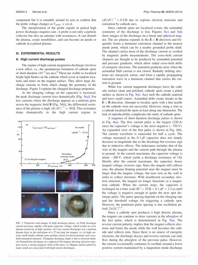
As the charging voltage on the capacitor is increased,the peak discharge current rises dramatically [Fig. 3(a)]. Forlow currents where the discharge appears as a uniform glowacross the magnetic field B [Fig. 3(b)], the differential resist-ance of the plasma is high ðdI=dVÞ$1 ’ 30 X. This resistancedrops dramatically in the high current regime to
ðdI=dVÞ$1 ’ 0:5 X due to copious electron emission andionization by cathode arcs.
Since cathode spots are localized events, the azimuthalsymmetry of the discharge is lost. Figures 3(c) and 3(d)show images of the discharge on a linear and spherical mag-net. The arc plasma expands in the E% B direction and fre-quently forms a luminous ionization channel to the nearestanode point, which can be a nearby grounded probe shaft.The channel carries most of the discharge current as verifiedby magnetic probe measurements. The cross-field currentchannels are thought to be produced by azimuthal potentialand pressure gradients, which allow radial cross-field driftsof energetic electrons. The potential gradients arise when theazimuthal Hall current is not closed. Radially drifting elec-trons are energized, ionize, and form a rapidly propagatingionization wave in a luminous channel that carries the cur-rent to ground.
While low current magnetron discharges leave the cath-ode surface clean and polished, cathode spots create a pittedsurface as shown in Fig. 3(e). Arcs melt the cathode materialand leave small craters. Azimuthal drifts create streaks in theE% B direction. Attempts to localize spots with a fine needleon the cathode were not successful. However, using a wire asa cathode localized the spots at least along one dimension. Thelack of reproducibility complicates the study of cathode spots.
A sequence of short duration discharge pulses is shownin Fig. 4(a). The first current pulse is the largest (220 A)since the capacitor’s voltage is the most negative ($750 V).An expanded view of the first pulse is shown in Fig. 4(b).The current waveform is sinusoidal for half a cycle. Thevoltage measured at the 0:1 lF capacitor does not simplydecrease in magnitude due to the discharge but reverses signdue to inductive effects. The inductance includes that of thewire to the magnet and the current path through the plasmato ground. At the current maximum, the capacitor voltage isabout $200 V, which yields a discharge resistance of 1 X.Shortly after the current maximum, the capacitor, hencemagnet voltage, reverses sign. Since the magnet still collectsions, the plasma floating potential near the magnet must belarger than the magnet voltage, but near zero at the wall inorder to collect electrons. With insufficient secondary elec-tron emission, the magnet no longer functions as a magne-tron cathode. When the current stops, the capacitor isrecharged on a time scale RC ¼ 25 X% 0:1 lF ¼ 2:5 ls untilthe voltage is negative enough to ignite the next spot dis-charge pulse. The pulse spacing depends on the charging rateand the threshold voltage for triggering a cathode spot.However, the minimum pulse spacing is one oscillation pe-riod, 2pðLCÞ1=2.
Since a cathode spot produces a high density plasma,the magnet can continue to draw currents in the afterglow ofthe first pulse, which is demonstrated in Fig. 5(a). Thereverse current polarity implies that the magnet collects elec-trons and forms the anode while the wall becomes the cath-ode and collects ions. Since there is no source of energeticelectrons, the discharge decays and reverse currents can onlyflow during the afterglow of the previous pulse. However,the current occasionally continues to oscillate around a lowerpositive current maintained by a magnetron mode discharge
FIG. 3. Properties and images of high discharge pulses. (a) Peak dischargecurrent increases rapidly with peak capacitor voltage, which results in a lowplasma resistivity at high currents. (b) Low current discharges for a uniformplasma layer in the mid-plane of a 27 cm long bar magnet. (c) At high cur-rents small bright cathode spots produce dense localized plasmas and cross-field ionization channels. Triangular discharge shape is due to electron drifts.(d) Nonuniform discharge on a spherical Nd magnet showing electron trans-port across a strong magnetic field (4 kG max). (e) Magnet surface pitted bymany small arcs associated with high current discharges.
083504-3 Stenzel et al. Phys. Plasmas 20, 083504 (2013)
This article is copyrighted as indicated in the article. Reuse of AIP content is subject to the terms at: http://scitation.aip.org/termsconditions. Downloaded to IP:
128.97.22.136 On: Thu, 19 Dec 2013 20:30:04
without cathode spots. From the oscillation frequency(f ’ 550 kHz) and the external charging capacitor (0:1 lF),one obtains the inductance of the entire current path, whichis determined to be L ¼ ðx2CÞ$1 ’ 0:84 lH. The reactanceof this L$ C circuit is ðL=CÞ1=2 ¼ 2:9 X while the resistanceis R ’ 1 X, thus the expected peak pulse current,Vcharge=ðL=Cþ R2Þ1=2 ’ 750 V=3:1 X ’ 240 A, is close tothe observed value of 220 A.
In order to validate the inductance measurement, the cir-cuit has been further simplified by connecting a straight wirefrom the capacitor through the chamber to ground. The ring-ing frequency is measured without plasma with the samepulsing circuit [Fig. 5(b)]. It yields a comparable, althoughsomewhat higher, inductance (L ’ 1:47 lH).
B. Cathode and anode spots on electrodes
It has been shown earlier that a very negatively biasedprobe emits secondary electrons, which create a plasma near apermanent magnet (see Fig. 2(c), part I8). Thus, it is not sur-prising to also observe cathode spots on probes, as shown inthe insert of Fig. 6. Instead of by the cathode, the plasma isnow produced by a pulsed plane Langmuir probe(1 cm% 1 cm Ta plate) while the magnet is floating. Figure 6shows the probe current for two different probe voltages.
FIG. 5. Current reversals and oscillations. (a) Strong magnet currents canoscillate and thereby reverse the current direction, turning the cathode intoan electron-collecting anode. The oscillation can also occur around a low dcdischarge. The oscillation frequency is determined by the circuit inductanceand the 0:1 lF capacitor. The damping yields the plasma resistance. (b)Without plasma, the current closure is established by a wire to ground,which produces a similar ringing frequency (see schematic inserted). Ityields the inductance and resistance of the circuit components.
FIG. 4. High-current discharge pulses. (a) Current pulses created when asmall capacitor is discharged periodically by the plasma. (b) Current and ca-pacitor voltage on an expanded time scale for the first pulse. A large induc-tive voltage reverses the capacitor voltage during the current drop. Theinductance arises from the wire between the capacitor and magnet and theplasma current to ground.
FIG. 6. Current to a plane Langmuir probe biased to $500 V and locatednear a floating magnet (see insert). The probe exhibits cathode spots, whichcreate time-varying currents similar to those when the magnet is biased(100–200 A and 1 ls). Thus, the peak current does not depend on the cathodesurface area but on the properties of the spot plasma. When the applied volt-age is reduced (bottom trace,) the peak current decreases and the pulse spac-ing increases. At still lower voltages, the cathode spots disappear and theprobe current drops by three orders of magnitude.
083504-4 Stenzel et al. Phys. Plasmas 20, 083504 (2013)
This article is copyrighted as indicated in the article. Reuse of AIP content is subject to the terms at: http://scitation.aip.org/termsconditions. Downloaded to IP:
128.97.22.136 On: Thu, 19 Dec 2013 20:30:04
The higher bias produces a large oscillatory current. Areduced bias produces smaller and repetitive pulses. The peakcurrent and pulse duration are comparable to those producedby cathode spots on the magnet (>100 A; 1 ls). Thus, thespot discharge current does not depend on the size of the cath-ode area but is determined by the spot size. Since the spot sizeis much smaller than the probe area, the current density mustbe Jspot # 100 A=cm2, which requires electron densitiesne # 1013 cm$3 for 1 eV electrons. Current reversals alsooccur on probes when the inductive voltage, L dI=dt, reversesthe capacitor voltage, which turns the probe into an anode.
Arcs are not only confined to negatively biased electro-des but are also seen on positive electrodes as “anode spots.”It occurs frequently when a grounded coaxial probe isbrought into the vicinity of the magnet and the end of theouter conductor is not insulated. Figure 7 shows an image ofan anode spot on a grounded probe shield, but not on thefloating probe itself. It sputtered some of the probe materialwhich left a white streak in the time exposure. By placing amagnetic probe close to the probe wire, the same magneticperturbation is observed as by placing the probe close to thewire leading to the magnet (not shown). Thus, the anode spotcarries the same current as the magnet and provides for thecurrent closure.
The current closure at the chamber wall is not trivialsince the skin depth for 1 MHz current oscillations is muchsmaller than the 5 mm thick Al chamber wall. Surface cur-rent must flow to chamber ports, which allow current closurebetween the inside and outside chamber surfaces. The rf cur-rent flow resembles that on a cutoff waveguide with holes.
C. Transient oscillations
The time-varying plasma properties and electromagneticeffects of spot discharges trigger oscillations in most probes.These can be orders of magnitude larger than plasma wave
signals. Transient probe or circuit oscillations can be charac-terized as decaying oscillations excited by short-durationevents such as spots. The frequencies of ringing signals arenearly independent of plasma parameters and the ringingmay last longer than the discharge. The ringing frequenciesare difficult to interpret but may arise from mismatching theprobes to coaxial cables even when the latter are properlyterminated into 50 X. At frequencies well above the ionplasma frequency, probe currents are dominated by displace-ment currents due to time-varying plasma potentials.
Figure 8(a) shows a typical transient effects from a spotdischarge. One spot arises at the start of the discharge andproduces a very steep current rise. It triggers a high fre-quency probe ringing response during the time interval Dt1
and a second lower frequency ringing during Dt2 started by acurrent discontinuity at the beginning of the current reversalwhen the inductive voltage has its peak positive value. AFast Fourier Transform (FFT) shows that the high frequencytransient contains a spectrum of harmonics of the low fre-quency ringing [Fig. 8(b)]. This feature suggests transmis-sion line resonances whose amplitude depends on the current
FIG. 8. Transient ringing due to spots. (a) Magnet current oscillation withcurrent jumps due to spots. (b) Transient oscillations from an rf probe, whichoccurs at different frequencies. (c) FFT of the ringing oscillation which cancontain multiples of a fundamental resonance. (d) FFT of the low frequencyringing oscillation excited after current reversal. Its frequency correspondsto the fundamental frequency of the ringing in (c).
FIG. 7. Anode spot on an exposed outer shield of a grounded coaxial probenear a magnetron discharge. The bright line is sputtered anode material. Theprobe shaft carries the same current as the wire to the magnet, hence pro-vides the current closure.
083504-5 Stenzel et al. Phys. Plasmas 20, 083504 (2013)
This article is copyrighted as indicated in the article. Reuse of AIP content is subject to the terms at: http://scitation.aip.org/termsconditions. Downloaded to IP:
128.97.22.136 On: Thu, 19 Dec 2013 20:30:04
rise time which triggers the ringing. The ringing is not visi-ble in the magnet current, hence a probe effect.
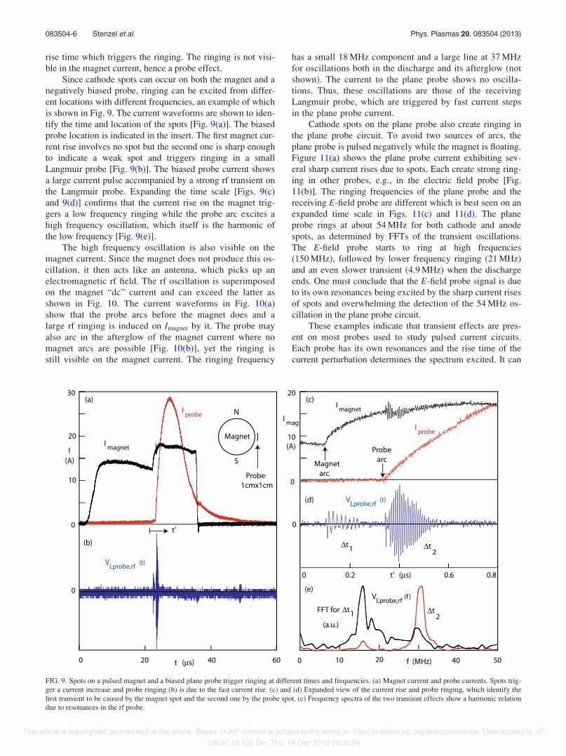
Since cathode spots can occur on both the magnet and anegatively biased probe, ringing can be excited from differ-ent locations with different frequencies, an example of whichis shown in Fig. 9. The current waveforms are shown to iden-tify the time and location of the spots [Fig. 9(a)]. The biasedprobe location is indicated in the insert. The first magnet cur-rent rise involves no spot but the second one is sharp enoughto indicate a weak spot and triggers ringing in a smallLangmuir probe [Fig. 9(b)]. The biased probe current showsa large current pulse accompanied by a strong rf transient onthe Langmuir probe. Expanding the time scale [Figs. 9(c)and 9(d)] confirms that the current rise on the magnet trig-gers a low frequency ringing while the probe arc excites ahigh frequency oscillation, which itself is the harmonic ofthe low frequency [Fig. 9(e)].
The high frequency oscillation is also visible on themagnet current. Since the magnet does not produce this os-cillation, it then acts like an antenna, which picks up anelectromagnetic rf field. The rf oscillation is superimposedon the magnet “dc” current and can exceed the latter asshown in Fig. 10. The current waveforms in Fig. 10(a)show that the probe arcs before the magnet does and alarge rf ringing is induced on Imagnet by it. The probe mayalso arc in the afterglow of the magnet current where nomagnet arcs are possible [Fig. 10(b)], yet the ringing isstill visible on the magnet current. The ringing frequency
has a small 18 MHz component and a large line at 37 MHzfor oscillations both in the discharge and its afterglow (notshown). The current to the plane probe shows no oscilla-tions. Thus, these oscillations are those of the receivingLangmuir probe, which are triggered by fast current stepsin the plane probe current.
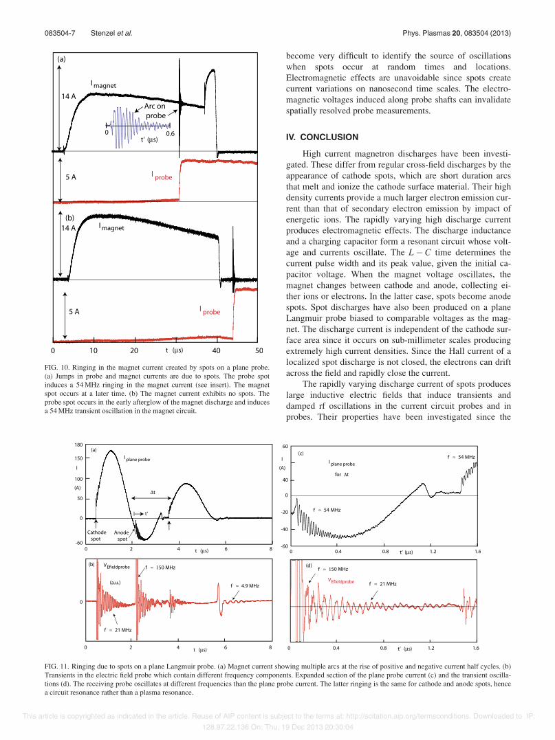
Cathode spots on the plane probe also create ringing inthe plane probe circuit. To avoid two sources of arcs, theplane probe is pulsed negatively while the magnet is floating.Figure 11(a) shows the plane probe current exhibiting sev-eral sharp current rises due to spots. Each create strong ring-ing in other probes, e.g., in the electric field probe [Fig.11(b)]. The ringing frequencies of the plane probe and thereceiving E-field probe are different which is best seen on anexpanded time scale in Figs. 11(c) and 11(d). The planeprobe rings at about 54 MHz for both cathode and anodespots, as determined by FFTs of the transient oscillations.The E-field probe starts to ring at high frequencies(150 MHz), followed by lower frequency ringing (21 MHz)and an even slower transient (4.9 MHz) when the dischargeends. One must conclude that the E-field probe signal is dueto its own resonances being excited by the sharp current risesof spots and overwhelming the detection of the 54 MHz os-cillation in the plane probe circuit.
These examples indicate that transient effects are pres-ent on most probes used to study pulsed current circuits.Each probe has its own resonances and the rise time of thecurrent perturbation determines the spectrum excited. It can
FIG. 9. Spots on a pulsed magnet and a biased plane probe trigger ringing at different times and frequencies. (a) Magnet current and probe currents. Spots trig-ger a current increase and probe ringing (b) is due to the fast current rise. (c) and (d) Expanded view of the current rise and probe ringing, which identify thefirst transient to be caused by the magnet spot and the second one by the probe spot. (e) Frequency spectra of the two transient effects show a harmonic relationdue to resonances in the rf probe.
083504-6 Stenzel et al. Phys. Plasmas 20, 083504 (2013)
This article is copyrighted as indicated in the article. Reuse of AIP content is subject to the terms at: http://scitation.aip.org/termsconditions. Downloaded to IP:
128.97.22.136 On: Thu, 19 Dec 2013 20:30:04
become very difficult to identify the source of oscillationswhen spots occur at random times and locations.Electromagnetic effects are unavoidable since spots createcurrent variations on nanosecond time scales. The electro-magnetic voltages induced along probe shafts can invalidatespatially resolved probe measurements.
IV. CONCLUSION
High current magnetron discharges have been investi-gated. These differ from regular cross-field discharges by theappearance of cathode spots, which are short duration arcsthat melt and ionize the cathode surface material. Their highdensity currents provide a much larger electron emission cur-rent than that of secondary electron emission by impact ofenergetic ions. The rapidly varying high discharge currentproduces electromagnetic effects. The discharge inductanceand a charging capacitor form a resonant circuit whose volt-age and currents oscillate. The L$ C time determines thecurrent pulse width and its peak value, given the initial ca-pacitor voltage. When the magnet voltage oscillates, themagnet changes between cathode and anode, collecting ei-ther ions or electrons. In the latter case, spots become anodespots. Spot discharges have also been produced on a planeLangmuir probe biased to comparable voltages as the mag-net. The discharge current is independent of the cathode sur-face area since it occurs on sub-millimeter scales producingextremely high current densities. Since the Hall current of alocalized spot discharge is not closed, the electrons can driftacross the field and rapidly close the current.
The rapidly varying discharge current of spots produceslarge inductive electric fields that induce transients anddamped rf oscillations in the current circuit probes and inprobes. Their properties have been investigated since the
FIG. 11. Ringing due to spots on a plane Langmuir probe. (a) Magnet current showing multiple arcs at the rise of positive and negative current half cycles. (b)Transients in the electric field probe which contain different frequency components. Expanded section of the plane probe current (c) and the transient oscilla-tions (d). The receiving probe oscillates at different frequencies than the plane probe current. The latter ringing is the same for cathode and anode spots, hencea circuit resonance rather than a plasma resonance.
FIG. 10. Ringing in the magnet current created by spots on a plane probe.(a) Jumps in probe and magnet currents are due to spots. The probe spotinduces a 54 MHz ringing in the magnet current (see insert). The magnetspot occurs at a later time. (b) The magnet current exhibits no spots. Theprobe spot occurs in the early afterglow of the magnet discharge and inducesa 54 MHz transient oscillation in the magnet circuit.
083504-7 Stenzel et al. Phys. Plasmas 20, 083504 (2013)
This article is copyrighted as indicated in the article. Reuse of AIP content is subject to the terms at: http://scitation.aip.org/termsconditions. Downloaded to IP:
128.97.22.136 On: Thu, 19 Dec 2013 20:30:04
large and sometimes long lasting oscillations interfere withplasma diagnostic applications.
The transient oscillation frequency is much higher thanthe L$ C oscillation of the discharge current. Thus, the rffrequency must be determined by the spot properties ratherthan the external circuit. Cathode and anode spots producedifferent ringing frequencies. Although the rf frequency iswell below the electron cyclotron frequency, it is unlikely tobe a whistler mode since the ringing is also observed on aprobe located outside the dipole magnetic field. The role ofthe return current channel in generating rf oscillations alsoneeds to be further investigated.
The effects of spot discharges on sputtering applicationshave not yet been explored but they are likely to affect theuniformity and sputtering rate compared to low power dcmagnetrons. Other potential applications could be to couplethe pulsed discharge power into a resonant circuit to generatehigh rf power (100 kW at 1 MHz).
ACKNOWLEDGMENTS
This work was supported in part by NSF/DOE GrantDE-SC0004660 and in part by the Austrian Science Fund
(FWF) under Grant No. 19901. Additional support by theUniversity of Innsbruck is acknowledged.
1J. A. Thornton, “Magnetron sputtering: Basic physics and application tocylindrical magnetrons,” J. Vac. Sci. Technol. 15, 171 (1978).
2P. J. Kelly and R. D. Arnell, “Magnetron sputtering: A review of recentdevelopments and applications,” Vacuum 56, 159–172 (2000).
3K. Sarakinos, J. Alami, and S. Konstantinidis, “High power pulsed magne-tron sputtering: A review on scientific and engineering state of the art,”Surf. Coat. Technol. 204, 1661–1684 (2010).
4J. T. Gudmundsson, “The high power impulse magnetron sputtering dis-charge as an ionized physical vapor deposition tool,” Vacuum 84,1360–1364 (2010).
5E. V. Barnat and K. Frederickson, “Two-dimensional mapping of electrondensities and temperatures using laser-collisional induced fluorescence,”Plasma Sources Sci. Technol. 19, 055015 (2010).
6B. J€uttner, “Cathode spots of electric arcs,” J. Phys. D: Appl. Phys. 34,R103–R123 (2001).
7A. R. Pal, J. Chutia, and H. Bailung, “Observation of instability in pres-ence of exb flow in a direct current cylindrical magnetron dischargeplasma,” Phys. Plasmas 11, 4719 (2004).
8R. L. Stenzel, J. M. Urrutia, C. T. Teodorescu-Soare, C. Ionita, and R.Schrittwieser, “Magnetic dipole discharges. I. Basic properties,” Phys.Plasmas 20, 083503 (2013).
9S. M. Shkolnik, “Anode phenomena in arc discharges: A review,” PlasmaSources Sci. Technol. 20, 013001 (2011).
10R. L. Stenzel, J. M. Urrutia, C. Ionita, and R. Schrittwieser, “Magneticdipole discharges. III. Instabilities,” Phys. Plasmas 20, 083505 (2013).
083504-8 Stenzel et al. Phys. Plasmas 20, 083504 (2013)
This article is copyrighted as indicated in the article. Reuse of AIP content is subject to the terms at: http://scitation.aip.org/termsconditions. Downloaded to IP: