20
Magnetic level gauge NA7-50 / 52 D-06-B-20482-EN-0.doc Edition 01/11
Magnetic level gauge
NA7-50 / 52
D-06-B-20482-EN-0.doc Edition 01/11
2
-Table of contents-
1. Health and safety instructions 4-5
1.1 General health and safety instructions ........................................ 4 1.2 Unit-specific safety instructions .................................................. 5 1.3 Exclusion of liability .................................................................. 5 2. Important information 6
2.1 Intended use ........................................................................... 6 3. Explanations 6
3.1 Scope of supply........................................................................ 6 3.2 System description ................................................................... 6 3.3 Function .................................................................................. 6
4. Technical data 7-8
4.1 Versions ............................................................................... 7-8 4.2 Type of connection ................................................................... 8 4.3 Materials ................................................................................. 8 4.4 Application limits ...................................................................... 8 4.5 Corrosion resistance ................................................................. 8 4.6 Identification plate / Marking ..................................................... 8
5. Construction 9
6. Assembly 9-11
6.1 Version with flange ................................................................... 9 6.2 Version with welding end......................................................... 10 6.3 Heat treatment of weldseams .................................................. 10 6.4 Flap indicator ......................................................................... 10 6.5 Float installation..................................................................... 10 6.6 Drain piping........................................................................... 10 6.7 Assembly of additional equipment ............................................ 11 7. Electrical connection 11
7.1 Magnetic switch...................................................................... 11 7.2 Primary element..................................................................... 11 8. Commissioning 12
8.1 Adjustment of indicating flaps .................................................. 12 8.2 Commissioning of unit together with the boiler........................... 12 8.3 Commissioning of unit if boiler is already in operating condition ... 12 8.4 Anti-frost device ..................................................................... 12

3
9. Maintenance 13-14
9.1 Cleaning of standpipe (2) and float (2.1) ................................... 13 9.2 Tightening torques.................................................................. 14 10. Drain valve 14-16
10.1 Construction ..................................................................... 14-15 10.2 Assembly .............................................................................. 15 10.3 Commissioning....................................................................... 15 10.4 Maintenance .......................................................................... 16 11. Spare parts 17
11.1 Magnetic level gauge .............................................................. 17 11.2 Drain valve ............................................................................ 17 12. Decommissioning 18
12.1 Disposal ................................................................................ 18 13. Supplement 18-19 13.1 Warranty............................................................................... 18 13.2 Declaration of Conformity ........................................................ 19

4
General health and safety instructions
1. Avoidance of danger for persons and property
• Only use unit for intended purpose. • No additional mountings and modifications on the unit without our approval. • Adhere to the standards for prevention of accidents and to the plant specific safety regulations. • Read and observe installation and operating instructions. 2. Application limits
Only use this unit according to these operating instructions and to the parameters agreed upon in the delivery contract (see identification plate) including the agreed operating conditions. 3. Avoidance of danger and damages
• Distribute these mounting and operating instructions to appropriate department “arrival of goods, works transport, mounting, commissioning and maintenance”.
• When passing the unit to a third party, these mounting and operating instructions must be enclosed in the national language of this third party.
• Only skilled and qualified personnel with special work order may work on the unit, which must be free of pipeline stress!
• Carefully read, observe and preserve these mounting and operating instructions. • Observe and adhere to the precautions marked in bold characters in the
sections of these mounting and operating instructions! • Avoid shocks and impacts during transport, which could damage the unit. • In case of intermediate storage take care for a dry and appropriate place where the
unit cannot be damaged. 4. Marking
In these mounting and operating instructions, the safety instructions are specially marked with the following symbols:
means danger to life and/or serious property damage in case of non-observance. Never ignore!
Danger means that you must pay special attention to the technical relationships.
Attention

5
Unit-specific safety instructions
The fitting is under pressure during operation! If flange connections, screw plugs or stuffing boxes are unfixed, hot water and steam will escape.
Carry out assembly and maintenance works only if plant is completely pressureless!
The fitting is hot during operation! Severe burns on hands and arms are possible. Wait until the unit has cooled before carrying out assembly and maintenance works!
Severe burns and scaldings on the whole body are possible!
Wait until the unit has cooled. In case of opening and disassembling the unit, residual medium can escape. Further evaporation is also possible on pressureless plant.
Sharp-edged interior parts can cause cutting damages on the hands! Always wear work gloves when exchanging packing, valve seat and valve cone!
Exclusion of liability
The IGEMA GmbH Mess- und Regelsysteme does not accept liability when a/m regulations, instructions and warning indications are not observed and adhered to. The operator is responsible for modifications on a unit of IGEMA (if they are not explicitly specified in the mounting and operating instructions). The magnetic switch may not be opened. Each warranty claim expires if the test seal is damaged.
2. Important information

6
2.1 Intended use Magnetic level gauge NA7-50 / 52: The magnetic level gauge is a liquid level gauge which can be used for steam boilers and containers. The indication is made via a float operated magnetic system. The product corresponding to the PED Directive 97/23/EEC has the CE-mark no. 0035 of the notified body. Applied rules as per TRD/AD2000 or ASME-Boiler.
3. Explanations
3.1 Scope of supply - Standpipe with indicating ledge - Float and new gasket are packed on the outside of the unit - Setting magnet is enclosed Additional equipment (also possible for existing devices): - Magnetic switch - Primary element MRK-… - Drain valve 3.2 System description
The level gauge indicates the level in the boiler indirectly. 3.3 Function The unit works according to the physical law of the communicating tubes. The liquid level in the standpipe (2) is the same as the one in the boiler. The liquid level is transmitted to the indicating ledge on the outside of the standpipe via a float with inner magnetic system located inside of the standpipe. The magnetic system actuates simultaneously additionally mounted switches (4) on the standpipe and/or a sensor (5) for remote liquid level transmission.
Design sketch see chapter 5
4. Technical data
7
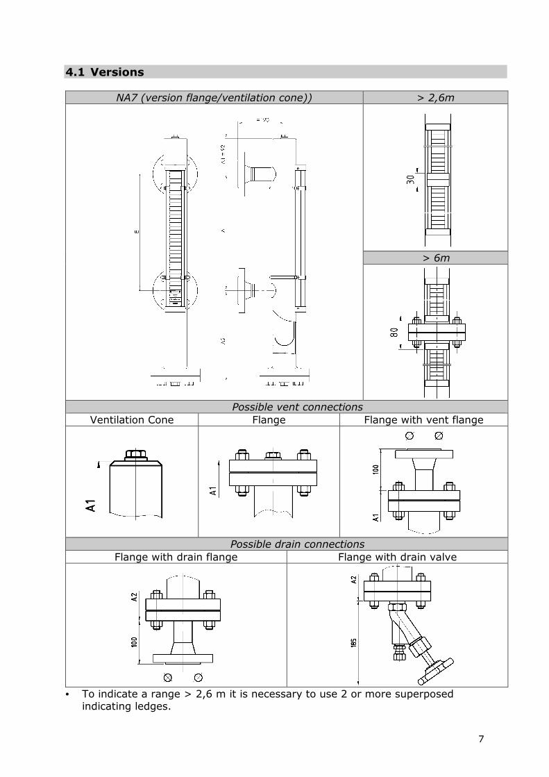
4.1 Versions
NA7 (version flange/ventilation cone)) > 2,6m
> 6m
Possible vent connections Ventilation Cone Flange Flange with vent flange
Possible drain connections Flange with drain flange Flange with drain valve
• To indicate a range > 2,6 m it is necessary to use 2 or more superposed indicating ledges.

8
• For level gauges longer than 6 m, the unit will be delivered in divided version with intermediate flanges.
Product designation: e.g. NA7-50 / 52 flange/ventilation cone
NA7 -50 / 52 Flange / Ventilation Cone Device Float diameter Drain Ventilation
4.2 Type of connection Standard : flanges according to DIN or ASME On request : welding end or Socket Welding according to DIN or ASME
4.3 Materials • Fluid side in stainless steel according to DIN or ASME. • Float made of stainless steel; for low medium density the float is made of
titan 4.4 Application limits
4.5 Corrosion resistance The safety of the unit is not influenced by corrosion if it is used as intended. 4.6 Identification plate / Marking The following data are indicated on the identification plate according to EN 19:
a Date of manufacture b Type of unit c Max. all. pressure d Max. all. temperature e Nominal pressure (not listed) f Nominal diameter
5. Construction
Max. all. pressure PS [bar] 20 50 Max. all. temperature TS [°C] 214 265
9
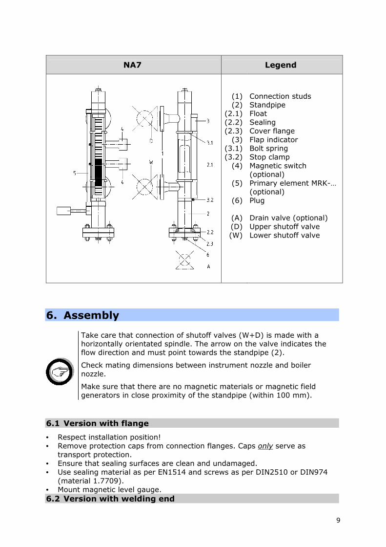
NA7 Legend
(1) (2)
(2.1) (2.2) (2.3)
(3) (3.1) (3.2)
(4)
(5)
(6)
(A) (D) (W)
Connection studs Standpipe Float Sealing Cover flange Flap indicator Bolt spring Stop clamp Magnetic switch (optional) Primary element MRK-… (optional) Plug Drain valve (optional) Upper shutoff valve Lower shutoff valve
6. Assembly
Take care that connection of shutoff valves (W+D) is made with a horizontally orientated spindle. The arrow on the valve indicates the flow direction and must point towards the standpipe (2).
Check mating dimensions between instrument nozzle and boiler nozzle.
Make sure that there are no magnetic materials or magnetic field generators in close proximity of the standpipe (within 100 mm).
6.1 Version with flange
• Respect installation position! • Remove protection caps from connection flanges. Caps only serve as
transport protection. • Ensure that sealing surfaces are clean and undamaged. • Use sealing material as per EN1514 and screws as per DIN2510 or DIN974
(material 1.7709). • Mount magnetic level gauge. 6.2 Version with welding end

10
• Respect installation position! • Remove protection caps from connection flanges. Caps only serve as
transport protection. • Assembly only by using welding process 111 (manual arc welding) and 141
(tungsten inert gas welding). 6.3 Heat treatment of weldseams
Supplementary temper tests of weldseams are not required. 6.4 Flap indicator
• The centre of the lower process connection is the reference point for the zero mark of the flap indicator (3).
• The flap indicator fixed by bolt springs (3.1) with stop clamp (3.2) to the standpipe (factory-made) can be turned into desired position. Also turn stop clamp !
6.5 Float installation
• The float (2.1) with inner magnetic system and the new gasket (2.2) are packed and fixed outside of the standpipe (2) when the unit is supplied.
• Open cover flange (2.3) • Carefully remove float packing • Insert float with top-heavy side upwards into standpipe (top-heavy side with
colour marking) • Tighten cover flange (2.3) and associated gaskets (2.2) with standpipe using
successively opposite diagonal tightening (see chapter 9.2)
Remove float before carrying out pressure test of boiler! Float may remain in standpipe if there are valve between boiler and standpipe which are closed during the test.
6.6 Drain piping • Check bolting drain valve (A) / standpipe (2) and retighten if necessary. • Mount drain piping on drain valve (A) (to be provided by the customer).
Ensure that drain piping has free outlet to atmosphere and is protected from pressure peaks!
• Close valves. 6.7 Assembly of additional equipment (for retrofitting, otherwise already pre-
installed)
• Remove indicating ledge before assembly of additional equipment • Magnetic switches and/or primary element are fixed without obscuring the
indication by means of integrated pipe saddle Assembly of magnetic switches or sensor may only be carried out in a maximum angle of 90° to the centre of the flap indicator.
11
Never insulate additional equipment.
• The magnetic switch is continuously adjustable in the whole indication area “E”. (see special data sheet)
• The centre of the lower process connection is the reference point for the zero mark of the sensor (marked in red).
(see special data sheet and operating instruction for primary element MRK-..)
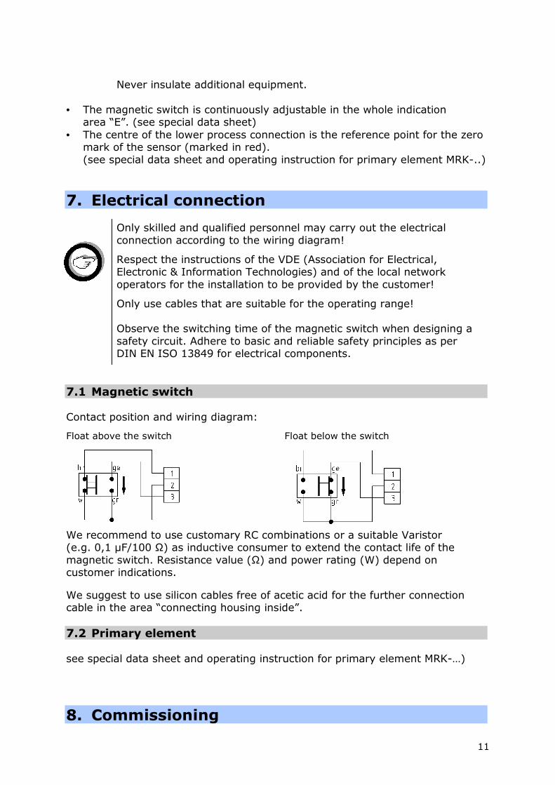
7. Electrical connection
Only skilled and qualified personnel may carry out the electrical connection according to the wiring diagram!
Respect the instructions of the VDE (Association for Electrical, Electronic & Information Technologies) and of the local network operators for the installation to be provided by the customer!
Only use cables that are suitable for the operating range! Observe the switching time of the magnetic switch when designing a safety circuit. Adhere to basic and reliable safety principles as per DIN EN ISO 13849 for electrical components.
7.1 Magnetic switch Contact position and wiring diagram:
Float above the switch Float below the switch
We recommend to use customary RC combinations or a suitable Varistor (e.g. 0,1 µF/100 Ω) as inductive consumer to extend the contact life of the magnetic switch. Resistance value (Ω) and power rating (W) depend on customer indications.
We suggest to use silicon cables free of acetic acid for the further connection cable in the area “connecting housing inside”. 7.2 Primary element see special data sheet and operating instruction for primary element MRK-…)
8. Commissioning

12
Unit may be hot during commissioning and during operation. Attention danger of life! Customer can possibly provide safety device.
8.1 Adjustment of indicating flaps Pass setting magnet (bottom-up) 3 times along the glass plate. The flaps above the zero mark are white and the flaps below the zero mark are red. (see figure in chapter 8.4) 8.2 Commissioning of unit together with the boiler
Check specifications of material, pressure and temperature!
• Close drain valve (A) / plug (6) (see sketch chapter 5). • Open shutoff valves W+D. • Check position of magnetic switch (2) in operating condition and adjust the
height if necessary 8.3 Commissioning of unit if boiler is already in operating
condition
• Close drain valve (A) / plug (6) (see sketch chapter 5). • Open slowly shutoff valve W and then shutoff valve D • Check position of magnetic switch (2) in operating condition and adjust the
height if necessary. 8.4 Anti-frost device Insulated units which are used in the area of temperatures below 0°C must be provided with a flap indicator with anti-frost device. Pass setting magnet bottom-up laterally of the anti-frost device to adjust the flaps.
9. Maintenance
Indicating ledge
13
When using viscous or crystallizing media, clean standpipe (2) and float (2.1) inside in regular intervals and during boiler revision.
Unit may be hot during commissioning and during operation. Attention danger of life! Customer can possibly provide safety device.
9.1 Cleaning of standpipe (2) and float (2.1) Purging of connection pipework including case:
• Close shutoff valves (W+D). • Slowly open drain valve (A) / plug (6) and drain medium • Slightly open valve D and close after approx. 2 seconds. • Slightly open valve W and close after approx. 2 seconds. • Close drain valve (A) / plug (6). • Close drain valve (A) / plug (6) • Fully open valves W+D after filling of standpipe
If this cleaning was not sufficient, dismount bottom/cover flange (2.3) and remove float (2.1).
Plant must be pressureless for disassembly works! Wait until unit has cooled!
• Close shutoff valves (W+D). • Open drain valve (A) / plug (6); unit is drained. • Caution! When dismounting, residual medium may escape and further
evaporation is also possible. • Remove cover flange (2.3). • Remove float and clean standpipe and float. • Insert float with top-heavy side upwards into standpipe (top-heavy side with
colour marking). • Always use new gaskets (2.2) when assembling the unit. Tighten bolts of
cover flange / standpipe in several steps using successively opposite diagonal tightening (see table in chapter 9.2) until reaching tightening torque Md max.
Close shutoff valves before carrying out preservation works or chemical cleaning of the boiler. Or even better: interrupt passage on flange connection of boiler nozzles by placing blind flanges.
For commissioning see chapter 8. Design sketch see chapter 5. 9.2 Tightening torques
14
Tightening torque Md → Md max
[Nm] in steps
all. pressure
PS
[bar] 1 2 3 4 5 6
32 35 50 65 75 - -
50 50 75 100 125 150 165
Tightening torques of screw plug (6) Md= 150 Nm
10. Drain valve
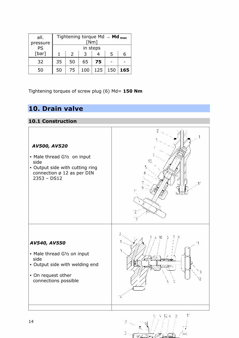
10.1 Construction
AV500, AV520
• Male thread G½ on input side • Output side with cutting ring connection ø 12 as per DIN 2353 – DS12
AV540, AV550 • Male thread G½ on input side • Output side with welding end • On request other connections possible
15
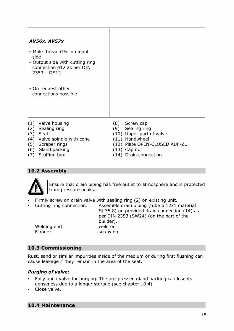
AV56x, AV57x • Male thread G½ on input side • Output side with cutting ring connection ø12 as per DIN 2353 – DS12 • On request other connections possible
(1) Valve housing (8) Screw cap (2) Sealing ring (9) Sealing ring (3) Seat (10) Upper part of valve (4) Valve spindle with cone (11) Handwheel (5) Scraper rings (12) Plate OPEN-CLOSED AUF-ZU (6) Gland packing (13) Cap nut (7) Stuffing box (14) Drain connection 10.2 Assembly
Ensure that drain piping has free outlet to atmosphere and is protected from pressure peaks.
• Firmly screw on drain valve with sealing ring (2) on existing unit. • Cutting ring connection: Assemble drain piping (tube ø 12x1 material St 35.8) on provided drain connection (14) as per DIN 2353 (SW24) (on the part of the builder).
Welding end: weld on Flange: screw on
10.3 Commissioning
Rust, sand or similar impurities inside of the medium or during first flushing can cause leakage if they remain in the area of the seat. Purging of valve:
• Fully open valve for purging. The pre-pressed gland packing can lose its denseness due to a longer storage (see chapter 10.4)
• Close valve. 10.4 Maintenance
16
Before carrying out maintenance works on drain valve, unit has to be pressureless and empty! Severe burns and scaldings on the whole body are possible!
Re-tightening of gland packing:
• If a valve is leaky, tighten screw cap (8) with open-end wrench (SW27) clockwisely until valve is tight. Spindle (4) has to stay movable. • Replace gland packing if re-tightening of packing was not successful. Replacement of packing:
• Screw off cap nut (13) and remove handwheel (11). • Unscrew upper part of valve (10). • Remove screw cap (8) and stuffing box (7). • Remove spindle with cone (4) upwards. • Push out gland packing (6) with scraper rings (5) from top and clean packing
space. Assembly:
• Grease spindle thread, insert from top and firmly tighten screws. • Place new greased packing with scraper rings (5). • Insert stuffing box (7). • Tighten screw cap (8). • Insert new sealing ring (9). • Grease thread of upper part of valve (10), screw in and tighten with
tightening torque Md = 220 Nm. • Place handwheel (11) and tighten cap nut (13). Replacement of complete upper part:
• For dismounting of component parts see “Replacement of packing” • Unscrew seat (3) with hexagon socket wrench SW11. • Grease seat thread, screw in and tighten with tightening torque Md = 55 Nm. • Replace complete upper part. • Place new spindle. • For assembly of component parts see above.
11. Spare parts
17
Always indicate article no. and serial no. (indicated on the identification plate) in case of
spare parts order!
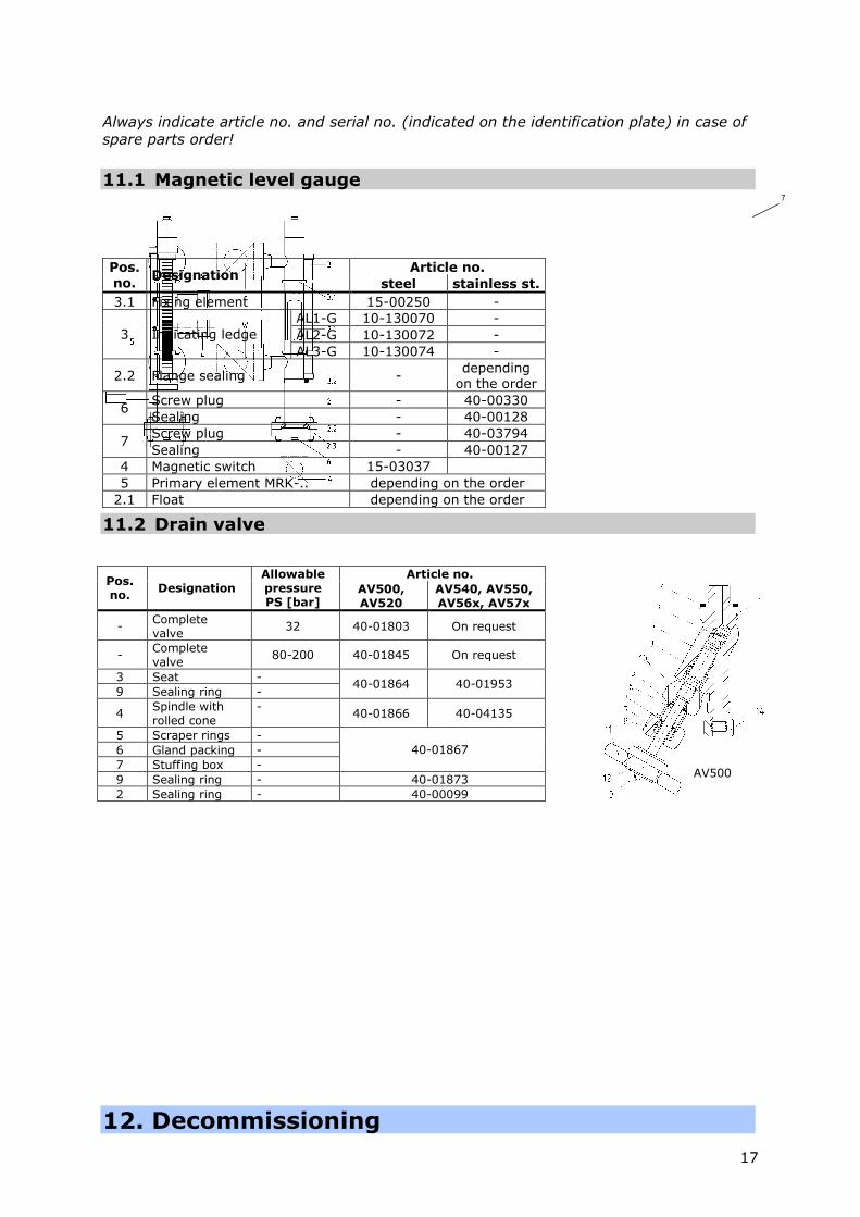
11.1 Magnetic level gauge
11.2 Drain valve
12. Decommissioning
Article no. Pos.
no. Designation
steel stainless st.
3.1 Fixing element 15-00250 - AL1-G 10-130070 - AL2-G 10-130072 - 3 Indicating ledge AL3-G 10-130074 -
2.2 Flange sealing - depending
on the order Screw plug - 40-00330
6 Sealing - 40-00128 Screw plug - 40-03794
7 Sealing - 40-00127
4 Magnetic switch 15-03037 5 Primary element MRK-.. depending on the order
2.1 Float depending on the order
Article no. Pos. no.
Designation Allowable pressure PS [bar]
AV500, AV520
AV540, AV550, AV56x, AV57x
- Complete valve
32 40-01803 On request
- Complete valve
80-200 40-01845 On request
3 Seat - 9 Sealing ring -
40-01864 40-01953
4 Spindle with rolled cone
- 40-01866 40-04135
5 Scraper rings - 6 Gland packing - 7 Stuffing box -
40-01867
9 Sealing ring - 40-01873 2 Sealing ring - 40-00099
AV500
7
18
Severe burns and scaldings on the whole body are possible!
Before detaching flange connections, screws of stuffing box cover screws or screw plugs, all connected lines must be pressureless (0 bar) and cooled off to ambient temperature (20°C)!
12.1 Disposal Dismount unit and separate waste products. When disposing the unit, observe legal regulations for waste disposal.
13. Supplement
Warranty
We accord a warranty period of 24 month on our products. A condition for that is the appropriate treatment according to these mounting and operating instructions. The warranty for wear and spare parts is restricted to material defects and construction faults. The magnetic switches are wear parts and are not included in the warranty. The sealings/gland packing installed in the valves are not included in the warranty.
19
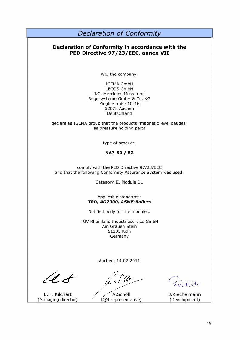
Declaration of Conformity
Declaration of Conformity in accordance with the PED Directive 97/23/EEC, annex VII
We, the company:
IGEMA GmbH LECOS GmbH
J.G. Merckens Mess- und Regelsysteme GmbH & Co. KG
Zieglerstraße 10-16 52078 Aachen Deutschland
declare as IGEMA group that the products “magnetic level gauges” as pressure holding parts
type of product:
NA7-50 / 52
comply with the PED Directive 97/23/EEC and that the following Conformity Assurance System was used:
Category II, Module D1
Applicable standards: TRD, AD2000, ASME-Boilers
Notified body for the modules:
TÜV Rheinland Industrieservice GmbH
Am Grauen Stein 51105 Köln Germany
Aachen, 14.02.2011
E.H. Kilchert A.Scholl J.Riechelmann (Managing director) (QM representative) (Development)
20
This high quality IGEMA product has been developed, manufactured and inspected in accordance with a quality management system according to DIN EN ISO 9001:2000. If on receipt of this unit you notice damage in transit or another cause for complaint despite our final quality inspection, please contact immediately our customer service, phone no. +49 (0) 241-56 87-0.
Created: Düsseldorf Authorized: Date: 27.05.2010


