Magnetic Plasmon Resonance Andrey K. Sarychev Ethertronics Inc., San Diego, CA 92121 Gennady Shvets Department of Physics, The University of Texas at Austin, Austin, TX 78712 Vladimir M. Shalaev School of Electrical and Computer Engineering, Purdue University, West Lafayette, IN 47907 January 12, 2006 Abstract It is demonstrated that metallic horseshoe-shaped (also referred to as u-shaped) nanostructures can exhibit a magnetic resonance in the optical spectral range. This magnetic plasmon resonance is distinct from the purely geometric LC resonance occurring in perfectly con- ducting split rings because the plasmonic nature of the metal plays the dominant role. Similarly to the electrical surface plasmon reso- nance, the magnetic plasmon resonance is determined primarily by the metal properties and nanostructure geometry rather than by the ratio of the wavelength and the structure’s size. Magnetic plasmon resonance occurs in nanostructures much smaller in size than the op- tical wavelength. Electromagnetic properties of periodically assembled horseshoe-shaped nanostructures are investigated, and the close prox- imity of the electrical and magnetic plasmon resonances is exploited in designing a negative index meta-material. Close to the magnetic plas- mon resonance frequency both magnetic permeability µ and electric permittivity ε can become negative, paving the way for the develop- ment of sub-wavelength negative index materials in the optical range. 1
Transcript
Magnetic Plasmon Resonance
Andrey K. SarychevEthertronics Inc., San Diego, CA 92121
Gennady ShvetsDepartment of Physics,
The University of Texas at Austin, Austin, TX 78712
Vladimir M. ShalaevSchool of Electrical and Computer Engineering,Purdue University, West Lafayette, IN 47907
January 12, 2006
Abstract
It is demonstrated that metallic horseshoe-shaped (also referred toas u-shaped) nanostructures can exhibit a magnetic resonance in theoptical spectral range. This magnetic plasmon resonance is distinctfrom the purely geometric LC resonance occurring in perfectly con-ducting split rings because the plasmonic nature of the metal playsthe dominant role. Similarly to the electrical surface plasmon reso-nance, the magnetic plasmon resonance is determined primarily bythe metal properties and nanostructure geometry rather than by theratio of the wavelength and the structure’s size. Magnetic plasmonresonance occurs in nanostructures much smaller in size than the op-tical wavelength. Electromagnetic properties of periodically assembledhorseshoe-shaped nanostructures are investigated, and the close prox-imity of the electrical and magnetic plasmon resonances is exploited indesigning a negative index meta-material. Close to the magnetic plas-mon resonance frequency both magnetic permeability µ and electricpermittivity ε can become negative, paving the way for the develop-ment of sub-wavelength negative index materials in the optical range.
1
1 Introduction
Extending the range of electromagnetic properties of naturally occurring ma-terials motivates the development of artificial (or meta-) materials. For ex-ample, it has recently been demonstrated that meta-materials may exhibitsuch interesting properties as negative dielectric permittivity ε < 0 (see,for example [1], [2]), negative magnetic permeability µ < 0 [3], and evenboth [4, 5]. The double-negative case of ε < 0 and µ < 0 (often referred toas the left-handed and negative refractive regime) is particularly interestingbecause of the possibility of making a "perfect" lens with sub-wavelengthspatial resolution [6]. In addition to the super resolution, unusual and some-times counter-intuitive properties of negative index materials (NIMs), whichalso referred to as left-handed materials (LHMs), make them very promisingfor applications in resonators, waveguides and other microwave and opticalelements [7, 8, 9, 10].Negative refraction has been convincingly demonstrated in the microwave
regime [5, 8, 9, 11]. For microwave NIMs, artificial magnetic elements (pro-viding µ < 0) are the split-ring resonators or the swiss roll structures. Inthe microwave part of the spectrum, metals can be considered as perfectconductors because the skin depth is much smaller than the metallic featuresize. The strong magnetic response is achieved by operating in the vicinityof the LC resonance of the split ring [3, 12]. The same technique of obtainingµ < 0 using split rings was recently extended to mid-IR [12] by scaling downthe dimensions of the split rings. In the microwave, as well as (to a lesserdegree) in the mid-IR part of the spectrum, metals can be approximatedas perfect conductors because the skin depth is much smaller than the fea-ture size of the structure. Therefore, the frequencies of the LC resonancesare determined entirely by the split ring geometry and size but not by theelectromagnetic properties of the metal. In accordance with this, the ringresponse is (resonantly) enhanced at some particular ratio of the radiationwavelength and the structure size. Thus we refer to the LC resonances ofperfectly conducting metallic structures as geometric LC (GLC) resonances.The situation drastically changes in the optical part of the spectrum,
where thin (sub-wavelength) metal components behave very differently whentheir sizes become less than the skin depth. For example, the electricalsurface plasmon resonance (SPR) occurs in the optical and near-IR parts ofthe spectrum due to collective electron oscillations in metal structures. Manyimportant plasmon-enhanced optical phenomena and applications of metal
2
nano-composites are based on the electrical SPR (see, for example, [13]).Plasmonic nature of the electromagnetic response in metals for optical/mid-IR frequencies is the main reason why the original methodology of GLCresonances in microwave/mid-IR spectral range is not extendable to higherfrequencies.For the optical range, NIMs with a negative refractive-index have been for
the first time demonstrated in the experiment [14] where the authors observedthe real part of the refractive index n = −0.3 at the telecommunicationwavelength of 1.5µm. In that report the authors experimentally verifiedtheir early theoretical prediction for negative refraction in an array of parallelmetal nanorods [15]. Note that the losses become progressively importantwith increasing frequency toward the optic band. Moreover, the elementarycell of the resulting structure is on order of the wavelength. Making a trueNIM requires the cell size to be less than λ/2. Therefore, miniaturization ofthe cell size is of major interest, and can be accomplished, for example, byutilizing plasmonic effects [16, 17, 18, 19].It is also necessary to take into account from the beginning that dielec-
tric permittivity ε = ε0 + iε00 and magnetic permeability µ = µ0 + iµ00 arecomplex values. The structure that exhibits the negative real dielectric per-mittivity ε0 ≈ −0.7 and negative real of magnetic permeability µ0 ≈ −0.3 ingreen light (λ ≈ 0.5µm) has been investigated in Ref. [20]. However ratherlarge imaginary components (µ00 ≈ 1.0 at the resonance) has not allowed theobservation of the negative refraction.Thus the demonstration of a negative index meta-material in the regime
where plasmonic effects are important remains elusive. Plasmonic effectsmust be correctly accounted for to design a meta-material with optical mag-netism. Below we show that specially arranged metal nanoparticles can sup-port, along with the electrical SPR, magnetic plasmon resonance (MPR).The MPR’s resonance frequency ωr can be made independent of the ab-solute characteristic structure size a and λ/a ≡ 2πc/ωa. The only definingparameters are the plasmonic permittivity εm(ω) and the structure geometry.Such structures act as optical nanoantennas by concentrating large electricand magnetic energies on the nanoscale at the optical frequencies. The mag-netic response is characterized by the magnetic polarizability αM with theresonant behavior similar to the electric SPR polarizability αE: real part ofαM changes the sign near the resonance and becomes negative for ω > ωr,as required for negative index meta-materials. We show that the electro-static resonances must replace (or strongly modify) GLC resonances in the
3
optical/mid-IR range if a strong magnetic response is desired.The idea of using electrostatic resonances for inducing optical magnetism
is relatively recent. For example, electrostatic resonances of periodic plas-monic nanostructures have been recently employed to induce magnetic prop-erties due to close proximity of adjacent nanowires [16, 17]. Higher mul-tipole electrostatic resonances were shown [18] to hybridize in such a wayas to induce magnetic moments in individual nanowires. Strong electrosta-tic resonances of regularly shaped nanoparticles (including nanospheres andnanowires) occur for −2 < ε0m < −1. The resistive damping characterized bythe ratio ε00m/ε
0m of the imaginary and real parts of the dielectric permittivity
of a metal is fairly strong for those frequencies corresponding to |ε0m| ∼ 1.However, ε00m/ε
0m is known to decrease for |εm| À 1. Therefore, there is
a considerable incentive to design nanostructures exhibiting resonances forε0m ¿ −1. Such horseshoe-shaped structures, first suggested in Ref. [21]are described below. Spectrally, these structures support strong magneticmoments at the frequencies higher than the microwave/mid-IR frequenciessupported by the traditional split ring resonators (see Refs. [3, 12] for details)and lower than the ultraviolet frequencies supported by the sub-wavelengthplasmonic crystals described in Refs. [17, 18]. Conceptually, the horseshoe-shaped structures described here are distinct from the earlier low frequencystructures because they are not relying on the GLC resonance for producinga strong magnetic response because plasmonic properties of the metal arevery important when the sizes are small and the operational frequencies arehigh. Below we present a three-dimensional theory of the magnetic resonancein a plasmonic structure and related two-dimensional numerical simulations.Specifically, here we develop a comprehensive theory and perform detailed
numerical simulations for negative index meta-materials based on horseshoe-shaped structures. The possibility of optical magnetism in such structureswas first theoretically predicted [21] and recently experimentally verified [22].Closely related split-ring resonator structures were also shown [23] to pos-sess optical magnetism. Here we demonstrate that such horseshoe-shapedstructures may have negative dielectric permittivity, in parallel with negativemagnetic permeability, and thus they can be used for building a metamaterialwith a negative- refractive index.
4
Figure 1: Currents in two parallel metal wires excited by external magneticfield H. Displacement currents, “closing”the circuit, are shown by dashedlines.
2 Analytical theory of magnetic plasmon res-onances
We consider first a pair of parallel metallic rods. The external magnetic fieldexcites the electric current in the pair of the rods as shown in Fig. 1. Themagnetic moment associated with the circular current flowing in the rodsresults in the magnetic response of the system. Suppose that an externalmagnetic fieldH = {0, H0 exp(−iωt), 0} is applied perpendicular to the planeof the pair (We suppose that magnetic field is along y axis and the rodsare in {x, z} plane). The circular current I (z) excited by the time-varyingmagnetic field flows in the opposite directions in the nanowires as shown inFig. 1. The displacement currents flowing between the nanowires close thecircuit. We introduce the "potential drop" U (z) =
R baEdl between the pair
where the integration is along the line {a (z) , b (z)}. To find the currentI (z) , we integrate the Faraday’s Law curlE = ik(H0+Hin) over the contour{a, b, c, d} in Fig. 1, where k = ω/c is a wave vector, and Hin = curlA is themagnetic field induced by the current. It is assumed that the nanowire length2a is much larger than the distance d between the nanowires and the radiusb of a nanowire. We also assume that kd¿ 1. Under these assumptions, thevector potential A is primarily directed along the nanowires (z direction).
5
The use of the integral form of the Faraday’s Law yields
(IR− ik2Az + dU/dz)∆z = −ikH0d∆z, (1)
where the pair impedance R ' 2/(σπb2) ≈ 8i/(εb2ω), where ε = 1 +i4πσ/ω ¿ −1 is the metal complex permittivity, and ±IR/2 are the electricfields on the surface of the nanowires. Note that the wire resistivity is explic-itly taken into account. This sets our calculation apart from the earlier workon the resonances of conducting split ring resonators [24] and conductingstick composites [2] because plasmonic resonances of the wire are now fullyaccounted for.Electric field E can be always presented in terms of the vector potential
A and electric potential φ as E = −∇φ + ikA. In the standard Lorentzgage the electric potential φ equals to φ (r1) =
Rexp (ikr12) q (r2) /r12 dr2
and the vector potential A (r1) = c−1Rexp (ikr12) j (r2) /r12 dr2, where r12 =
|r1 − r2| , q and j are charge and current density correspondingly. In the caseof two long wires the currents flow inside the wires. Correspondingly thevector potential A has the only component in the direction z of the wiresA = {0, 0, Az}. Since the vector potential A is perpendicular to the line{a (z) , b (z)} the potential drop U in Eq. (1) equals to U (z) =
R baEdl =φa−
φb, where φa and φb are the electric potential in the points a (z) and b (z).We consider the excitation of the antisymmetric mode when the currents inthe wires are the same in absolute value but are opposite in the direction (seeFig. 1). Correspondingly the electric charge per unite length Q (z) = Qa =−Qb. We assume that the diameter b of the wire is much smaller than thedistance d between them and the wire length 2a À d. Then the potentialdrop U (z) between the pair estimates as U (z) = Q(z)/C, where the interwire capacitance C is independent of the coordinate z and is estimated inthe Appendix as C ' [4 ln(d/b)]−1.The vector potential Az (z) is proportional to the electric current Az (z) =
(L/c) I (z) /2, where the wire pair inductance is estimated as L ' 4 ln (d/b)(see Appendix.) Note that both C and L are purely geometric factors thatdo not depend on the plasmonic nature of the rods. The product LC canbe estimated as LC ' 1. Yet, in the above consideration we never assumedthat the wires are made from the perfect metal or from a metal with realconductivity, i.e., imaginary permittivity. Moreover, the two wire nanoan-tenna has most interesting behavior when metal dielectric constant is realand negative. The plasmonic nature of the metal is accounted for below.
6
We substitute U (z) andAz (z) into Eq. (1), taking into account the chargeconservation law dI/dz = iωQ (z), and obtain a differential equation for thecurrent:
d2 I (z)
d z2= −g2I (z)− Cdω2
cH0, (2)
where −a < z < a, I (−a) = I (a) = 0, and the parameter g is given as
g2 = k2hLC − 8C
¡(kb)2 εm
¢−1i. (3)
The two-wire antenna is resonantly excited whenG = ga = Nπ/2, whereN isan integer. Note that the material properties of the metal enter the resonantparameter G through the dielectric permittivity εm. In the context of thewire pair, the earlier discussed GLC resonances [3, 15, 12, 24, 26] correspondto the wire thickness b much larger than the skin depth (k2 |εm|)−1/2. Thisapproximation, typically valid for microwave and mid-IR frequencies, yieldsg = k/
√LC and the resonant condition ka = π/2, also known as the antenna
resonance.Let’s consider the opposite ("electrostatic", as explained below) limit of¯̄̄
8C [(kb)2εm]−1¯̄̄À 1. In the electrostatic regime G depends only on the
metal permittivity and the aspect ratio:
G2 ' −2(a/b)2 ln (d/b) /εm, (4)
but not on the wavelength and absolute length of the wires. Sharp resonancein Eq. (2) requires that G2 be positive, possibly with a very small imagi-nary part. Indeed, for IR/visible frequencies εm is negative (with a smallerimaginary part) for typical (Ag, Au, etc.) low loss metals. Metal dielectricconstant εm can be approximated by the Drude formula:
εm (ω) ∼= εb − (ωp/ω)2 / (1− iωτ/ω) , (5)
where εb is a "polarization" constant, ωp is the plasma frequency, and ωτ =1/τ is the relaxation rate. For considered here silver nanoantennas the con-stant εb approximates as εb ≈ 5, the plasma frequency ωp ≈ 9.1 and therelaxation rate ωτ ≈ 0.02 [28]. For example, at λ = 1.5µm the silver dielec-tric constant estimates as ε0m ≈ −120 and ε00m/ |εm| ≈ 0.025.We consider now the electric field in the system of two conducting rods
still assuming the electrostatic limit when the propagation constant G is
7
given by Eq. (4). The electric charge Q (z) and the current I (z) (Q (z) =(iω)−1 dI (z) /dz) are given by solution of Eq. (2)
Q (z) = Q0sin (Gz/a)
cosG, (6)
I (z) = iQ0aω
G
µ1− cos (Gz/a)
cosG
¶, (7)
where Q0 = ib d kH0
√−εm/h4√2 ln3/2(d/b)
i. Using the Lorentz gauge we
can write the equation for the electric potential
φ (r) =
Zq (r1)
exp (ikR1)
R1dr1 −
Zq (r2)
exp (ikR2)
R2dr2, (8)
where q (r1) and q (r2) are electric charges distributed over the surface of therods 1 and 2, R1 = |r− r1|, R2 = |r− r2|, and the integration goes over therods 1 and 2. We consider the electric field between the rods, i.e., in {z, x}plane (see Fig. 1) and assume that |x| ¿ a, |z| < a, and the distances to therods d1 = |x− d/2| À b and d2 = |x+ d/2| À b. Then we can integrate inEq. (8) over the cross-section of the rod after which it takes the one-dimensionform
φ (x, z) =
Z a
−aQ (z1)
∙exp (ikR1)
R1− exp (ikR2)
R2
¸dz1, (9)
where the linear charge density Q (z1), obtained from q (r1) by integrationover the rod circumference, is given by Eq. (6) [Q (z1) = −Q (z2)], the dis-tances R1 and R2 take the following form R1 =
qd21 + (z − z1)
2, R2 =qd22 + (z − z1)
2. Two terms in the square brackets in Eq. (9) cancel when|z − z1| > d, as it is discussed in the Appendix. Since we assume that kd¿ 1and d ¿ a we can put the exponents exp (ikR1) ' exp (ikR1) ' 1 and ex-tend the integration in Eq. (9) from z1 = −∞ to z1 =∞. Resulting integralis solved explicitly and we obtain the analytical equation for the electricpotential in the system of two nanowires
φ (x, z) = 2 ln
¯̄̄̄d/2 + x
d/2− x
¯̄̄̄Q (z) , (10)
where Q (z) is given by Eq. (6). Extrapolation of this result to the surfaceof the wires gives the potential drop U (z) = φ (d/2− b, z)−φ (−d/2 + b, z) =
8
4 ln (2d/b)Q (z) .Thus we obtain that the inter-wire capacitanceC = Q (z) /U (z)= 4 ln (d/b) is a constant, which is independent of the coordinate z, in agree-ment with estimate done in the Appendix.The vector potential A = {0, 0, A} is calculated in a similar way
A (x, z) ' 1
c
Z a
−aI (z1)
∙exp (ikR1)
R1− exp (ikR2)
R2
¸dz1
' 1
c
Z ∞
−∞I (z1)
∙1
R1− 1
R2
¸dz1 '
2
cln
¯̄̄̄d/2 + x
d/2− x
¯̄̄̄I (z) . (11)
where the electric current is given by Eq. (7). Extrapolating to the vectorpotential A to the surface of the first wire (x = d/2−b) we obtain 2cA = LI,where the inter-wire inductance L equals to L ' 4 ln (d/b) . The inductanceL is also independent of the coordinate z in agreement with the Appendix.Since the inter-wire capacitance C and inductance L both remain constantalong the wires, the Maxwell equations reduce to an ordinary differentialequation (2).The electric field E = −∇φ+ ikA is calculated from the potentials (10)
and (11) as
Ex = −2Q0 d
(d/2)2 − x2sin(
Gz
a) sec(G), (12)
Ez = −2Q0
aGln
¯̄̄̄d/2 + x
d/2− x
¯̄̄̄× (13)∙
G2 cos(Gz
a) sec(G)− a2 k2
µ1− cos(Gz
a) sec(G)
¶¸, (14)
where we still assume that |x| ¿ a, |z| < a, |x− d/2| À b and |x+ d/2| Àb. The transverse electric field Ex changes its sign with the coordinate zvanishing at z = 0. Yet, on average the ratio |Ex| / |Ez| is estimated near theresonance (G ≈ π/2) as |Ex| / |Ez| ∼ a/dÀ 1, that is the transversal electricfield is on average much larger than the longitudinal field at MPR. Near thewires transverse field Ex increases even more: |Ex| ∼ Q0/b. The potentialdrop ∆U between the points x1 = d/2+ l/2 and x2 = d/2− l/2 (2b < l¿ d)is estimated from Eq. (13) as −2lQ (z) /d, and the corresponding electric fieldEout ' − 2Q (z) /d. This field should be considered an external field for thewire at the coordinate y = d/2. The internal transverse potential drop acrossthe wire is estimated as |Uin| ' b |Eout| / |εm| ' 2 |Q (z)| b/ (d |εm|), where εm
9
is the metal dielectric constant, which is assumed to be large |εm| À 1. Theproblem of the internal transverse field closely resembles the classical problemof the field induced in a dielectric cylinder by another charged cylinder placedparallel to the first cylinder. An elegant solution of the problem can be foundin Ref. [25], Sec.7. In the discussed case |εm| , d/b À 1 it gives the aboveobtained estimate for Uin. The ratio of the potential drop Uin across a wireto the potential drop U (z) between the wires equals to¯̄̄̄
Uin (z)
U (z)
¯̄̄̄' b
d |εm| ln (d/b)¿ 1. (15)
For any practical purpose we can neglect Uin in comparison to U , whichallows to reduce the problem of charge and current distribution in the twowire system to the solution of the ordinary differential equation (2) for theelectric current I(z). Condition (15) is important for the developed analyticaltheory of MPR in the system of two thin rods. However, we can envision asystem (e.g. two closely packed metal nanowires or hemispheres) that stillreveals MPR, but condition (15) is not applied.To clarify the nature of the resonance, it is instructive to compute the
ratio of the electric and magnetic energies at the resonance:
EEEM∼ c2
C−1R|Q (z) |2 dz
LR|I (z) |2 dz ≈ g2
k2≈ 1− 2
ln (d/b)k2b2 |εm|, (16)
where we assume that the spatial frequency g, given by Eq. (3), is close tothe resonance (ga ≈ π/2) and use the expressions for the specific capacitanceC ' [4 ln(d/b)]−1 and inductance L ' 4 ln (d/b) derived in the Appendix.
In the electrostatic limit¯̄̄8C [(kb)2εm]
−1¯̄̄À 1 we obtain UE/UM À 1 thus
explaining the name given to this regime. Because of the symmetry of theelectric potential considered here, it is clear that such polarization cannot beinduced by any uniform electric field. Therefore, the discussed resonance canbe classified as the dark mode [30].The electric current I (z) is found from Eq. (2) and used to calculate the
magnetic moment of the wire pair m =(2c)−1R[r× j (r)] dr, where j (r) is
the density of the current and the integration is over the two nanowires. Thuswe obtain
m =1
2H0a
3 ln (d/b) (kd)2tanG−G
G3. (17)
The metal permittivity εm has a large negative value in the optical/near-IRrange while its imaginary part is small; therefore, the magnetic moment m
10
has a resonance at G ≈ π/2 (see Eq. 3) when m attains large values. For atypical metal we can use the Drude formula (5) for εm, where the relaxationparameter is small ωτ/ω ¿ 1. Then the normalized magnetic polarizabilityαM has the following form near the MPR:
αM =4πm
H0V=
16 a dωp
λ2 ωrp2 ln(d/b)
[1− ω/ωr − iωτ/ (2ωr)]−1 , (18)
where V = 4abd, and MPR frequency ωr = b π ωpp2 ln(d/b)/(4a). Note that
the magnetic moment contains a pre-factor ω2da/c2 ¿ 1 that is small in theelectrostatic limit valid for sub-wavelength nanostructures, as was predictedearlier [18]. Close to the resonance (G = π/2) the enhancement factor canbe very large for optical and infrared frequencies because of the high qualityof the plasmon resonance for ωr ¿ ωp. Therefore, the total pre-factor inEq. (18) can be of the order of one, thereby enabling the excitation of astrong MPR.Although the electric field energy near resonance is also very high, it is
primarily concentrated in the perpendicular to the wires component of theelectric field connecting the two wires as it was discussed after Eqs. (12) and(13). If the wavevector of the propagating wave is in the plane of the wires,and perpendicular to the wires, then the described above MPR does notstrongly affect the electric field component parallel to the wires. The inte-gral from the electric field, which is generated in magnetic resonance betweenthe wires, exactly equals to zero as it follow from Eqs. (12) and (13). Envi-sioning a composite material that consists of such wire pairs, we expect thatthe magnetic plasmon resonance will not contribute to the dielectric permit-tivity in the direction parallel to the wires. Therefore, such a medium is notbi-anisotropic [24] and can be described by two effective separate parame-ters: ε and µ. Prior work on inducing magnetic moments in nanostructuredmaterials [17, 18] in the electrostatic regime dealt with highly symmetric(round) nanowires. Here we demonstrate that magnetic moment can alsobe induced in the strongly non-symmetric (specifically, horseshoe-shaped)nanostructures with a large negative value of ε.We now consider a metal nanoantenna that has a horseshoe shape, which
is obtained from a pair of nanowires by shorting it at one of the ends (see
Fig. 2). When the quasi-static condition¯̄̄8C [(kb)2εm]
−1¯̄̄À 1 holds, the elec-
tric current I (z) in a horseshoe nanoantenna can be obtained from Eq. (2),where the boundary condition changes to Iz=a = (dI/dz)z=0 = 0 and, as
11
Figure 2: Optical magnetic permeability µ = µ1 + µ2 (µ1— continous line,µ2—dashed line) estimated from Lorenz-Lorentz formula for the compositecontaining @ shaped silver nanoantennas; volume concentration p = 0.3;left curves: a = 200nm, d = 50nm, b = 13nm; right curves a = 600nm,d = 90nm, b = 13nm; silver dielectric constant is estimated from the Drudeformula (5).
above, a À d À b. It is easy to check that the magnetic polarizabilityαM is still given by Eq. (18), where a is now equal to the total length ofthe horseshoe nanoantenna. Therefore, the horseshoe nanoantenna providesthe same magnetic polarizability αM at the twice shorter length. Magneticpermeability µ = µ1 + iµ2 for a metamaterial where the silver horseshoenanoantennas are oriented in one direction (”z” direction in Fig. 1) and areorganized in the periodic square lattice is shown in Fig. 2; the optical pa-rameters for silver were taken from [28]. As one can see in the figure, thenegative magnetism can be observed, for example, in the near-infrared partof the spectrum, including the telecommunication wavelength of 1.5µm.
3 Numerical Simulations of two-dimensionalstructures
To obtain a magnetically active in the optical range material, it might bemore convenient to employ (and much easier to model) a "two-dimensional"
12
Figure 3: Magnetic plasmon resonance in a silver horseshoe-shaped nano-antenna placed in a maximum of external field H0 which is directed per-pendicular to the plane; the frequency corresponds to λ = 1.5 µm; silverdielectric constant is estimated from the Drude formula (5).
meta-material, with the nanoantennas having a horseshoe shape in x, y planeand infinitely extended in z−direction. When the quasi-static condition|k2bdεm| ¿ 1 holds (b and d are thickness and distance between the op-posite walls, correspondingly), the MPR frequency ωr is defined by the equa-tion G2 = 2a
p−2/ (εmbd) = π/2. The resonant magnetic field is shown in
Fig. 3. The finite elements code FEMLAB [27] was used to calculate thefield distribution. Note that the magnetic field inside the horseshoe is largeand of the opposite sign with the external field H0, resulting in a negativemagnetic permeability in a close proximity to the magnetic plasmon reso-nance. To estimate the effective magnetic permeability we use an earlierdeveloped approach [13], which gives µz = 1 + p (sH0)
−1 R (Hin −H0) ds =
(32/π) a2 pλ−2 (π/2−G2)−1 for a plasmonic crystal composed by the horse-
shoe nano-antennas, where Hin is the magnetic field inside a horseshoe, theintegration is over the area s = da, p is the concentration of the nanoanten-nas organized in a square lattice. For a good optical metal, such as gold orsilver, µz becomes large and negative for ω > ωr. For example, the magnetic
13
Figure 4: Optical magnetic permeability µ = µ1 + iµ2 (µ1— continuous line,µ2—dashed line) of the composite containing silver nanoantennas shown inFig. 3 organized in a square lattice; volume concentration p = 0.4; silverdielectric constant is estimated from the Drude formula (5).
permeability (both real and imaginary parts) of a metamaterial composedof silver horseshoes has a sharp resonance for ω = ωr shown in Fig. 4. Thereal part µ1 of the optical magnetic permeability turns negative for ω > ωr.Figure 4 also reveals the spectral range λ ≥ 1 µm where µ1 is still less than−1 while the relative losses are small: δ = µ2/µ1 ¿ 1. The losses are crucialfor a such application of NIM as the perfect lens. Losses could, in principle,be further reduced by cooling the metal nanoantennas to cryogenic temper-atures. Simple estimates show that even at the liquid nitrogen temperaturethe electron mean free path becomes of the order of the horsshoes size. Theoptical properties of metals are not well understood when the mean free pathbecomes larger than the nanoantenna size. For these reasons we only considermeta-materials at the room temperature.To illustrate the effective magnetic properties of the horseshoe meta-
materials, we simulated em wave propagation in the plasmonic crystal com-posed from silver nano-antennas shown in Fig. 3. (The first three horseshoecolumns are well seen in Fig. 5a). The em wave is incident on the crystalfrom the left, its vacuum wavelength is λ = 1.4µm. The wave is evanescentin the crystal, as can be clearly seen from Fig. 5, and the transmittanceT < 10−6. This evanescence is due to the negative magnetic permeability ofthe crystal that could be rather large at the resonance (see Fig. 4). One wayof making this crystal transparent is to fill the space between the columnsof the horseshoes by a material with negative dielectric constant ε = −3.
14
Figure 5: Wave propagation through a two-dimensional (infinitely extendedin the normal to the page direction) plasmonic crystal near the plasmonmagnetic resonance. The crystal is composed of the horseshoe-shaped sil-ver nano-antennas shown in Fig. 3, volume filling ratio p = 0.4, λ = 1.4 µm.Magnetic fieldH of the incident em wave is directed along z−axis perpendic-ular to plane of picture; Hz = 1 in the incident wave. (Left) Spaces betweenthe horseshoes are filled with vacuum: no propagation. (Right) Spaces be-tween the horseshoes are filled with a hypothetical ε = −3 material: wavepropagates into the structure.
We speculate that such a modification can lead to a double-negative meta-material. This is confirmed by the numerical simulations. The results areshown in Fig. 5 (right). Indeed, the addition of a negative-ε material turnsour negative-µmeta-material into transparent NIM. Note that the negative-εmaterial was added only between the adjacent columns of horseshoe-shapednano-antennas. No additional material was placed in the exterior of thenanoantenna. This was done intentionally because modification of the nanos-tructure region where most of the magnetic field is concentrated is known [29]to affect the magnetic effective permittivity.Interestingly, the horseshoes themselves can exhibit a double-negative be-
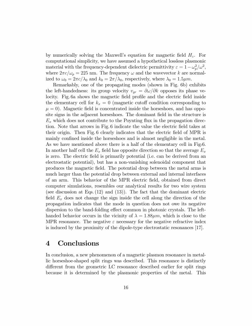
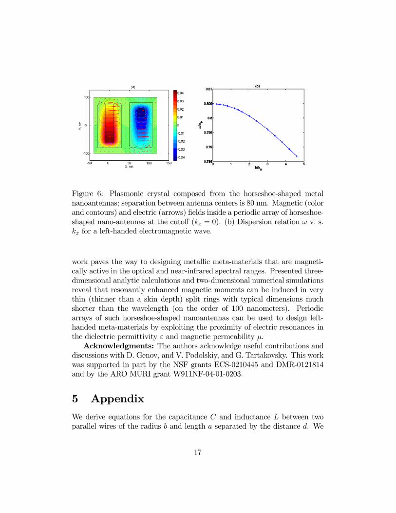
havior when they are closely packed. We designed a two-dimensional denseperiodic structure consisting of alternating up and down horseshoe nanoan-tennas. One half of the elementary cell is shown in Fig. 6a; another half of theelementary sell is obtained by 180◦ degree rotation in xy plane. (The struc-ture then repeats itself in x and y directions; separation between antennacenters is 80nm, horizontal periodicity is 160 nm, vertical periodicity is 400nm; see Fig. 5). Dispersion relation ω(kx) for the electromagnetic wave prop-agating through the periodic structure in x direction has been calculated
15
by numerically solving the Maxwell’s equation for magnetic field Hz. Forcomputational simplicity, we have assumed a hypothetical lossless plasmonicmaterial with the frequency-dependent dielectric permittivity ε = 1−ω2p/ω2,where 2πc/ωp = 225 nm. The frequency ω and the wavevector k are normal-ized to ω0 = 2πc/λ0 and k0 = 2π/λ0, respectively, where λ0 = 1.5µm.Remarkably, one of the propagating modes (shown in Fig. 6b) exhibits
the left-handedness: its group velocity vgr = ∂ω/∂k opposes its phase ve-locity. Fig. 6a shows the magnetic field profile and the electric field insidethe elementary cell for kx = 0 (magnetic cutoff condition corresponding toµ = 0). Magnetic field is concentrated inside the horseshoes, and has oppo-site signs in the adjacent horseshoes. The dominant field in the structure isEx which does not contribute to the Poynting flux in the propagation direc-tion. Note that arrows in Fig. 6 indicate the value the electric field takes attheir origin. Then Fig. 6 clearly indicates that the electric field of MPR ismainly confined inside the horseshoes and is almost negligible in the metal.As we have mentioned above there is a half of the elementary cell in Fig.̇6.In another half cell the Ex field has opposite direction so that the average Ex
is zero. The electric field is primarily potential (i.e. can be derived from anelectrostatic potential), but has a non-vanishing solenoidal component thatproduces the magnetic field. The potential drop between the metal arms ismuch larger than the potential drop between external and internal interfacesof an arm. This behavior of the MPR electric field, obtained from directcomputer simulations, resembles our analytical results for two wire system(see discussion at Eqs. (12) and (13)). The fact that the dominant electricfield Ex does not change the sign inside the cell along the direction of thepropagation indicates that the mode in question does not owe its negativedispersion to the band-folding effect common in photonic crystals. The left-handed behavior occurs in the vicinity of λ = 1.88µm, which is close to theMPR resonance. The negative ε necessary for the negative refractive indexis induced by the proximity of the dipole-type electrostatic resonances [17].
4 Conclusions
In conclusion, a new phenomenon of a magnetic plasmon resonance in metal-lic horseshoe-shaped split rings was described. This resonance is distinctlydifferent from the geometric LC resonance described earlier for split ringsbecause it is determined by the plasmonic properties of the metal. This
16
Figure 6: Plasmonic crystal composed from the horseshoe-shaped metalnanoantennas; separation between antenna centers is 80 nm. Magnetic (colorand contours) and electric (arrows) fields inside a periodic array of horseshoe-shaped nano-antennas at the cutoff (kx = 0). (b) Dispersion relation ω v. s.kx for a left-handed electromagnetic wave.
work paves the way to designing metallic meta-materials that are magneti-cally active in the optical and near-infrared spectral ranges. Presented three-dimensional analytic calculations and two-dimensional numerical simulationsreveal that resonantly enhanced magnetic moments can be induced in verythin (thinner than a skin depth) split rings with typical dimensions muchshorter than the wavelength (on the order of 100 nanometers). Periodicarrays of such horseshoe-shaped nanoantennas can be used to design left-handed meta-materials by exploiting the proximity of electric resonances inthe dielectric permittivity ε and magnetic permeability µ.Acknowledgments: The authors acknowledge useful contributions and
discussions with D. Genov, and V. Podolskiy, and G. Tartakovsky. This workwas supported in part by the NSF grants ECS-0210445 and DMR-0121814and by the ARO MURI grant W911NF-04-01-0203.
5 Appendix
We derive equations for the capacitance C and inductance L between twoparallel wires of the radius b and length a separated by the distance d. We
17
suppose from the beginning that b ¿ d and d ¿ a. We also suppose thatthe dielectric constant εm of the wires is large in absolute value |εm| À 1whereas the skin depth δ ∼ k
p|εm| ¿ b as it is explained in the text. To
find the capacitance C we first calculate the electric potential Φa in the pointwith coordinate ra at the surface of the wire (point a in Fig. 1) obtaining
Φa =
Zq1 (r1)
exp (ikra1)
ra1dr1 +
Zq2 (r2)
exp (ikra2)
ra2dr2, (19)
where ra1 = |ra − r1| , ra2 = |ra − r2|, q1 and q2 are the electric chargesdistributed over the surface of the rods; the integration goes over the surfaceof the first (a, d) and second (b, c) rods in Fig. 1. For further considerationwe choose the coordinate system {x, y, z} with z axis along the (a, d) rod,origin in the center of the system and the x axis connecting the axes of therods so that y axis is perpendicular to the plane of two rods. We introducethe vector d = {d, 0, 0} between the wires and two dimensional unit vectorρ (φ)= { cosφ, sinφ} in {x, y} plane, where φ is the polar angle. Thenthe vectors in Eq. (19) can be written as ra (φa, za) = {b ρ (φa) + d/2, za} ,r1 (φ1, z1) = {b ρ (φ1) + d/2, z1} , and r2 (φ2, z2) = {b ρ (φ2)− d/2, z2}. Itfollows from the symmetry of the problem that the electric charge q1(φ, z) =−q2(φ+ π, z) (recall that we consider antisymmetric mode when the electriccurrents in the rods are equal in absolute values but follows in the oppositedirections.) We rewrite Eq. (19) splitting it in two parts
∆ρ2 satisfy |∆ρ1|, |∆ρ2| < 2 so that the the second terms in the radicals inEq. (21) are much less than a.The electric currents in the rods and, correspondingly, electric charge q
changes with coordinate z on the scale ∼ a which is much larger than thedistance d between the rods. Therefore we can neglect z variation of theelectric charge for |∆z| < d. On the other hand the term in the squarebrackets in Eq. (21) vanishes as ∼ d2/ |∆z|3 for |∆z| > d. This allows toreplace in Eq. (21) the charge q (z, φ) by its value q (za,φa) in the observationpoint ra obtaining
Φ(0)a (za, φa) =
2πZφ=0
q (za,φ)
aZz=−a
[1p
∆z2 + b2∆ρ21− (24)
1q∆z2 + (b∆ρ2−d)2
]dz bdφ; (25)
the accuracy of this replacement is about (d/a)2 ¿ 1. Since we considerthe quasistatic limit when the distance between the rods d ¿ λ and themetal dielectric constant |εm| À 1 the potential lines in {x, y} plane areclose to the static case. Therefore we can safety suppose that the an-gle distribution of the electric charge q (z, φ) is the same as it would bein the case of two infinite metal cylinders in the static case: q (z, φ) =
Q (z)q(d/b)2 − 4 / (2π (d+ 2b cosφ)), where Q (z) is the electric charge per
unit length of the rod so thatR φ=2πφ=0
q (z,φ) b dφ = Q (z) . Then the integralin Eq. (24) gives the
Φ(0)a (z) = Q (z) arccosh
µd2
2 b2− 1¶+O
¡(d/a)2
¢, (26)
where the second term includes all corrections to the integral (21) due tofinite size of the system. For the thin wires, considered here, when the radiusb is much smaller than the distance d between the wires the potential Φ(0)a
The second term Φ(1)a in Eq. (20) is small in the limit of a ¿ λ, i.e.,
kra1, kra2 ¿ 1. The real part of Φ(1)a gives a small correction ∼ (d/a)2 to the
19
potentialΦ(0)a that can be neglect. The imaginary part is important regardlessof its absolute value since it gives so-called radiative losses. To estimate thelosses we assume that b/d¿ 1 and neglect the angle dependence of the chargedistribution. Then we expand Eq. (23) in series of k and linearly approximateQ (z) ' q1z (recall that Q (z) is an odd function of z) obtaining
Φ(1)a (z) ' −iQ (z) (ak)3 (kd)2 /45, (28)
where we neglect the terms with higher orders on k as well as all terms onthe order of (bk)2 .Due to the symmetry of the system the potential difference U = Φa −
Φb between points a and b (see Fig. 1; za = zb) equals to U = 2Φa. Thecapacitance C defined as C = Q (z) /U (z) is given by
1
C' 2 arccosh
£(d/ b)2 /2− 1
¤− i
2
45(ak)3 (kd)2 ' (29)
4 ln(d
b)− i
2
45(ak)3 (kd)2 , (30)
where the first term is the capacitance between two parallel infinite cylin-ders (see [25] Ch. 3 ); the second term gives the radiative losses due to theretardation effects.Consider now the inductance L between the wires. To find the inductance
L we first calculate the vector potential Aa in the point with coordinate rainside the wire. We neglect the edge effects and assume that the vectorpotential is parallel to the axes of the wires obtaining
Aa =1
c
Zj (r)
µexp (ikra1)
ra1− exp (ikra2)
ra2
¶dr, (31)
where ra1 = |ra − r| and ra2 = |ra−r+ d|, j (r1) is the density of the currentand the integration goes over the volume of the first wire. We considerthe quasistatic case when the skin effect is small (kb
p|εm| ¿ 1). Then the
electric current uniformly distributes over the cross-section of a wire andj (r) = I (z) / (πb2). Following the procedure used above for calculating theelectric potential, the vector potential is expressed as Aa = A
(0)a +A
(1)a , where
A(0)a =1
c
ZI (z)
πb2
µ1
ra1− 1
ra2
¶dr, (32)
20
A(1)a =
ZI (z)
πb2
µexp (ikra1)− 1
ra1− exp (ikra2)− 1
ra2
¶dr. (33)
The term A(0)a estimates in the same way as Φ(0)a . As result we obtain the vec-
tor potential A(0)a averaged over the cross-section of the wire in the followingform
A(0)a (z) ' I (z)
2c[4 ln(
d
b) + 1], (34)
where I (z) is electric current, and we neglect terms on the order (b/d)2 ¿ 1and (d/a)2 ¿ 1. To estimate Eq. (33) we expand it in series on k obtainingthat the linear term equals to zero, k2 term gives small correction (∼ (kd)2)to A(0)a and the third order on k gives the radiative losses, namely
A(1)a ' i(kd)2k1
c
ZI (z) dz ∼ 2iI (z)
c(kd)2ka, (35)
where we rather arbitrary neglect variation of the current over the rod lengthin transition to the second estimate. We obtain inductance L form the equa-tion Aa −Ab = 2Aa = (L/c)I (z) as
L = 4 ln(d
b) + 1 + 4i(kd)2ka.
The first two terms correspond to the self-inductance per unit length of asystem of two parallel infinite wires ([25], Ch.34.) This estimate as well asEq.( 30) are certainly invalid near the ends of the rods, but in calculating thecurrent distribution I (z) and magnetic moment this region is unimportant.We are now in a position to compare the radiation losses (given by imag-
inary parts of capacitance C and inductance L) and the ohmic loss in themetal wires. In near infrared spectral region the dielectric constant εm fora "good" optical meal (Ag, Au, etc.) can be estimated from the Drude for-mula (5) as εm (ω) ∼ (ωp/ω)2 (1− iωτ/ω)
−1, where ωp is plasma frequencyand ωτ ¿ ω ¿ ωp is the relaxation rate. Thus we obtain that the real partof the rod resistance Rohm ∼ 8
¡ωτ/ω
2p
¢(a/b2) should be compared with "ra-
diation" resistance Rrad ∼ (kd)2(ka)2/c. For the silver nanowires, consideredin the paper, the ohmic losses either larger (Rohm > Rrad) or much larger(Rohm À Rrad) than the radiation losses. Therefore we can neglect the imag-inary parts of the capacitance C and inductance L and approximate themfor simplicity as
L ' 1
C' 4 ln d
b. (36)
21
This estimate is of logarithmic accuracy; its relative error is on the order of(4 ln d/b)−1 . Note that the radiation losses crucially depend on the parameterka. Magnetic plasmon resonance address in this paper becomes very broadwhen ka > 1, placing a rather sever constraint on the length 2a of the wire.
References
[1] J. B. Pendry, A. J. Holden, W. J. Stewart, and I. Youngs,Phys. Rev. Lett. 76, 4773 (1996).
[2] A. N. Lagarkov, A. K. Sarychev, Y. R. Smychkovich, and A. P. Vino-gradov, J. Elect. Waves and Appl. 6, 1159 (1992); A. N. Lagarkov andA. K. Sarychev, Phys. Rev. B 53, 6318 (1996);
[12] S. Linden, C. Enkrich, M. Wegener, J. Zhou, T. Koschny, C.M. Souk-oulis, Science 306, 1351 (2004); N. Katsarakis, T. Koschny, M. Kafesaki,E. N. Economy, C. M. Soukoulis, Appl. Phys. Lett. 84, 2943 (2004).
22
[13] A.K. Sarychev and V.M. Shalaev, Phys. Rep. 333, 275 (2000).
[14] V. M. Shalaev, W. Cai, U. Chettiar, H.-K. Yuan, A. K. Sarychev, V. P.Drachev, and A. V. Kildishev, arXiv:physics/0504091, Apr. 13, (2005);Laser Phys. Lett. 3, 49-55 (2006); Opt. Lett. 30, 3356-3358 (2005).
[15] V.A. Podolskiy, A.K. Sarychev, and V.M. Shalaev, J. Non-lin. Opt. Phys. Mat. 11, 65 (2002); Optics Express 11, 735 (2003);A.K. Sarychev, V.P. Drachev, H.-K, Yuan, V.A. Podolskiy, and V.M.Shalaev, SPIE Proceedings, 5219, 92, San Diego (2003).
[16] G. Shvets, Phys. Rev. B 67, 035109 (2003).
[17] G. Shvets and Ya. A. Urzhumov, Phys. Rev. Lett. 93, 243902 (2004).
[18] G. Shvets and Ya. A. Urzhumov, J. Opt. A: Pure Appl. Opt. 7, S23(2005).
[19] G. Shvets and Y. A. Urzhumov, "Negative index meta-materials basedon two-dimensional metallic structures", J. Opt. A: Pure Appl. Opt. 7(2005) (in press).
[20] A.N. Grigorenko, A.K. Geim, H.F. Gleeson, Y. Zhang, A.A. Firsov, I.Y.Khrushchev, and J. Petrovic, Nature, 438, 335 (2005)
[21] A.K. Sarychev and V.M. Shalaev, SPIE Proceedings, 5508, 128 (2004).
[22] C. Enkrich, M. Wegener, S. Linden, S. Burger, L. Zschiedrich,F. Schmidt, J. Zhou, Th. Koschny, C. M. Soukoulis, arXiv:cond-mat/0504774 v.1, 29 Aprl 2005.
[23] T. J. Yen, W. J. Padilla, N. Fang, D. C. Vier, D. R. Smith, J. B. Pendry,D. N. Basov, and X. Zhang, Science 203, 1494 (2004).
[24] R. Marques, F. Medina, and R. Rafii-El-Idrissi, Phys. Rev. B 65, 144440(2002).
[25] D. Landau and E.M. Lifshitz, Electrodynamics of Continuous Media,2nd ed. (Pergamon, Oxford, 1984).
[27] FEMLAB Reference Manual 2003 Version 2.3 Comsol AB, Sweden.
[28] U. Kreibig and M. Vollmer, Optical Properties of Metal Clusters,Springer-Verlag, Berlin, 1995; P.B. Johnson and R.W. Christy, Phys.Rev. B 6, 4370 (1972).
[29] A. L. Pokrovsky and A. L. Efros, Phys. Rev. Lett. 89, 093901 (2002).
[30] M.I. Stockman, S.V. Faleev, and D.J. Bergman, Phys. Rev. Lett. 87,167401 (2001).