MAHARASHTRA STATE BOARD OF TECHNICAL EDUCATION (Autonomous) (ISO/IEC - 27001 - 2005 Certified) _____________________________________________________________________________________________ Page 1 of 26 SUMMER – 15 EXAMINATIONS Subject Code: 17622 Model Answer Important Instructions to examiners: 1) The answers should be examined by key words and not as word-to-word as given in the model answer scheme. 2) The model answer and the answer written by candidate may vary but the examiner may try to assess the understanding level of the candidate. 3) The language errors such as grammatical, spelling errors should not be given more importance. (Not applicable for subject English and Communication Skills) 4) While assessing figures, examiner may give credit for principal components indicated in the figure. The figures drawn by candidate and model answer may vary. The examiner may give credit for any equivalent figure drawn. 5) Credits may be given step wise for numerical problems. In some cases, the assumed constant values may vary and there may be some difference in the candidate’s answer s and model answer. 6) In case of some questions credit may be given by judgment on part of examiner of relevant answer based on candidate’s understanding. 7) For programming language papers, credit may be given to any other program based on equivalent concept.
Transcript
MAHARASHTRA STATE BOARD OF TECHNICAL EDUCATION (Autonomous)
Subject Code: 17622 Model Answer Important Instructions to examiners: 1) The answers should be examined by key words and not as word-to-word as given in the model answer scheme. 2) The model answer and the answer written by candidate may vary but the examiner may try to assess the understanding level of the candidate. 3) The language errors such as grammatical, spelling errors should not be given more importance. (Not applicable for subject English and Communication Skills) 4) While assessing figures, examiner may give credit for principal components indicated in the figure. The figures drawn by candidate and model answer may vary. The examiner may give credit for any equivalent figure drawn. 5) Credits may be given step wise for numerical problems. In some cases, the assumed constant values may vary and there may be some difference in the candidate’s answers and model answer. 6) In case of some questions credit may be given by judgment on part of examiner of relevant answer based on candidate’s understanding. 7) For programming language papers, credit may be given to any other program based on equivalent concept.
MAHARASHTRA STATE BOARD OF TECHNICAL EDUCATION (Autonomous)
Various stage involved in basic shearing process: Stage 1: As the top cutting member is moved downwards and brought to bear on the metal with continuing pressure, the top and bottom surfaces of the metal are deformed. Stage 2: As the pressure increases the internal fibres of the metal are subjected to deformation. This is plastic deformation prior to shearing. Stage 3: After a certain amount of plastic deformation the cutting member begin to penetrate. The uncut metal work hardens at the edges. Stage 4: Fractures begin to run into this work hardened metal from the points of contact of the cutting members. When these fractures meet, the cutting members penetrate the whole of the metal thickness.
02
marks for
diagram
0.5
mark
0.5
mark
0.5
mark
0.5
mark
04
MAHARASHTRA STATE BOARD OF TECHNICAL EDUCATION (Autonomous)
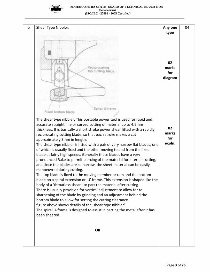
The shear type nibbler: This portable power tool is used for rapid and accurate straight line or curved cutting of material up to 4.5mm thickness. It is basically a short stroke power shear fitted with a rapidly reciprocating cutting blade, so that each stroke makes a cut approximately 3mm in length. The shear type nibbler is fitted with a pair of very narrow flat blades, one of which is usually fixed and the other moving to and from the fixed blade at fairly high speeds. Generally these blades have a very pronounced Rake to permit piercing of the material for internal cutting, and since the blades are so narrow, the sheet material can be easily manoeuvred during cutting. The top blade is fixed to the moving member or ram and the bottom blade on a spiral extension or 'U' frame. This extension is shaped like the body of a 'throatless shear', to part the material after cutting. There is usually provision for vertical adjustment to allow for re-sharpening of the blade by grinding and an adjustment behind the bottom blade to allow for setting the cutting clearance. figure above shows details of the 'shear type nibbler'. The spiral U-frame is designed to assist in parting the metal after it has been sheared.
OR
Any one type
02 marks
for diagram
02 marks
for expln.
04
MAHARASHTRA STATE BOARD OF TECHNICAL EDUCATION (Autonomous)
This portable nibbling machine does not operate on the same principle as the shear type. A punch and die is employed instead of shearing blades and the nibbling principle is a special application of punching. The advantage of these machines is that they will effect certain operations that cannot be accomplished on other shearing machines. For example, they may be used to cut out apertures which could only otherwise be produced by means of specially designed punches and dies set up in a powerful press. These portable power tools are used for rapid and accurate straight line or curved cutting of material from approximately 1.62mm to 3.2mm thickness. Like the shear type machine the top cutting tool (a punch) reciprocates at fast short strokes. Punch type nibblers are available, in various sizes and the punch reciprocates at a rate of 350 to 1400 strokes per minute over a die nibbling out the material by the simple principle of overlapping punching and only a slight finishing is necessary to produce
02 marks
for diagram
02 marks
for expln.
MAHARASHTRA STATE BOARD OF TECHNICAL EDUCATION (Autonomous)
a smooth clean edge. Although these machines are generally used for cutting material up to 3.2mm thickness, there are heavy duty machines available capable of cutting steel up to 6.35mm thickness. One main advantage of nibbling over shearing is that there is less distortion of the work. The figures above shows details of the punch type nibbler.
c Flame lighting: The procedure used for lighting a welding torch is adopted when lighting a cutting torch, but with some difference. The fuel gas regulator is set to the correct working pressure in the normal way and the oxygen regulator is set to the correct working pressure with the cutting oxygen valve on the torch in the open position. --- The fuel gas is lit and the flame adjusted, until it ceases to smoke. --- The heating oxygen valve is then opened and adjusted (similar to a
neutral flame setting) until there is a series of nicely defined white inner cones in the flame (in the case of the multi-port type nozzle) or a short white conical ring, if the nozzle is of the annular port type.
--- The cutting oxygen valve is then opened at this stage and the flame readjusted to a neutral condition. The oxygen cutting valve is then closed and the torch is ready for use.
Extinguish the flame: The correct procedure to extinguish the flame is as follows; --- Turn off the cutting oxygen. --- Close the fuel gas control valve. --- Close the heating oxygen control valve.
02 marks
02 marks
04
d The difference between ‘folding’ and ‘bending’ is so slight that they are both carried out with the same purpose in view which is to deflect the metal from one flat plane to another so that it stays there permanently. If the deflection is sharp and the radius small, the metal is said to be folded .e.g. a single fold or hem. Should the curvature be large and the deflection cover a large area, it is called bending .e.g. the rolling of a hollow body, such as a cylinder. Folding or bending involves the deformation of a material along a straight line in two dimensions only.
04 marks
04
MAHARASHTRA STATE BOARD OF TECHNICAL EDUCATION (Autonomous)
Simple piercing, blanking and similar operations. Fitting, assembling, punching and embossing thin sheets below 1mm thickness only.
It is very versatile. Tool changing is rapid and simple. With the correct tooling one can punch coin, tube end form, bend, slot, form, dimple, clinch fasteners, edge fold, rubber form, etc.
Mass production for a particular tooling arrangement is possible but time consuming due to human intervention.
Etc. Etc.
02 marks
for each point
04
f Pre-forming of ends is an operation prior to rolling of plates and sheet metals in order to remove flats at the two meeting edges after rolling. The need is to obtain a true cylinder without flats where the opposite edges touch.
02 marks
02
marks
04
g High strength friction grip bolts (HSFG): HSFG Bolts are of high tensile strength and used in conjunction with high strength nuts and hardened steel washers in structural steel works. The bolts are tightened to a specified minimum shank tension so that transverse loads are transferred across the joint by friction between the plates rather than by shear across the bolt shank. These bolts have high yield strength. They should conform to IS: 3757-1985. They are tightened by torque wrenches and require hardened washers to induce initial tensions, which causes friction between the plate surfaces. Due to friction, there is no slip in the joint and therefore the joints with HSFG bolts are called friction type or non-slip type joints. These bolts are made by a special cold working process which includes two operations: heading and thread rolling. Close tolerances ensure accuracy and heat treatment is carried out afterwards. The surfaces in contact must be free from paint, oil, dirt, loose rust and scale. Clearance --- The diameter of the bolt hole is usually 1.6mm larger than the nominal diameter bolt shank.
02 marks
01 mark
01 mark
04
MAHARASHTRA STATE BOARD OF TECHNICAL EDUCATION (Autonomous)
The rivet shank is split in two parts made of relatively soft material with
a formed head on one side. The rivet shank is inserted through the hole
in the parts to be joined such that it projects a set distance out of the far
end of the hole. The mandrel is inserted from top and pushed with a
blow of hammer due to which the bifurcated end of rivet on other side
gets split outwards and other side is locked.
02
marks for
(expln.)
b Parameters Bolting Riveting
Cost Low cost High cost
Reliability Less High
Labor skills Unskilled to semi - skilled Semi – skilled to skilled
Joint strength Low (fluctuating loads) High (fluctuating loads)
02 mark each
08
c For Huge Smith Vertical plate bending machine: • For bending cylinders from large to small diameters used in the production of pressure vessels, boilers, nuclear plant and legs/piles for oil platforms and modules • Sizes from 300 – 5000 Tonnes or more for plate widths up to 4.5 meters and thicknesses to 200mm cold • The vertical machine requires minimum crane attendance and occupies minimum floor space • Complete cylinders can be formed in a floor to floor time of 20 mins or less depending on diameter • Plate edge pre-setting is easily carried out using the direct acting hydraulic force of the machine • Adjustable bending centres provide the most suitable conditions for bending all sizes and thicknesses of plates • Crane attendance is not required once the plate is entered into the machine • RE-rounding and correction of weld seam can easily be carried out • Machine can be used to form cones and for plate straightening and also can be used for heavy duty flanging work including closed boxes A vertical angle ring bender is shown below for pictorial representation purpose only;
04 marks
(expln.)
04 marks (diag.)
08
MAHARASHTRA STATE BOARD OF TECHNICAL EDUCATION (Autonomous)
1- Foot pedal, 2- Rest for sheet, 3- Table, 4- Slide holding blade, 5- Hold down attachment, 6- Side wall The treadle operated guillotine shearing machine is economical to be use in small metal shop for cutting sheets. The sheet up to 1.5mm(16swg)thick are cut into strips. The blade has 4 working edges which provided 4 times cutting life of the blade.
OR
any one guillotine
machine
02 marks
for diagram
02 marks
08
MAHARASHTRA STATE BOARD OF TECHNICAL EDUCATION (Autonomous)
Motorised shearing machine: 1. table, 2.Hold down attachment (Pressure Pad) 3 .sIide 4. Table 5.Main gear and its cover 6. Driving motor with cover Parts of motorised shearing machine slide: This carries the top blade or blades. In the machine where the working length is large the number of blade segments is more than one. This is named as upper bar also. i) Blades: Blade actually cuts the sheet. It is like flat finished bar. All four edges are provided clearance for efficient cutting, thereby avoids frequent stoppages for regrinding. These are fixed with help of screws and are made of high carbon steel or high speed steel. ii) Hold down attachment: This attachment is used to grip the sheet before it is cut and operates simultaneously. iii)Table: The sheet is brought over here for cutting. It is fitted with front gauge and side gauge for squaring. Adjustable back gauge is carried on slides. iv)Side walls: The side walls are fabricated or cast which support the table and are braced by stay rods fastened to the table. They are designed to withstand operational cutting forces and provide stability to machine for long life without showing any sign of cracking or
02 marks
for diagram
02 marks for any
two parts
MAHARASHTRA STATE BOARD OF TECHNICAL EDUCATION (Autonomous)
deformation. v) Clutch: The clutch is fitted to the press along with the main gear to engage every time the pedal is pressed. The cutting process is continuous so long the pedal is pressed and disengages immediately no sooner the pedal is released. Working:
When power is transmitted to the blade it starts moving downward. A sufficient clearance is provided between the bottom and top blade. The top blabe is inclined at a considerable angle called as shear angle which is approximately 50 with horizontal because of which area under shear is greatly reduced and consequently the force required to shear the material is also considerably reduced Shear Force= Area under shear X Shear strength of material A typical guillotine machine is provided with fixed side gauge extension arm, adjustable front gauge, table or bed and bottom blade as shown in figure. The sheet to be cut is held against fixed side gauge and the front and back gauges are adjusted according to the required dimension of sheet to be cut.
02 marks
for diag.
02 marks
for expln.
MAHARASHTRA STATE BOARD OF TECHNICAL EDUCATION (Autonomous)
Cropping: Cutting by shearing is quick and probably the most economical production method. The shearing of rolled steel sections is performed indies designed to suit the section. The dies are mounted in a special shearing machine. This operation is commonly referred to as cropping.
02 marks for any
one diag
02
marks for
expln.
08
MAHARASHTRA STATE BOARD OF TECHNICAL EDUCATION (Autonomous)
Notching is removal of material by making a notch. In most fabrication shops, cutting operations on rolled steel sections are carried out on power machines. Machines are available which perform a combination of cutting operations, such as punching, shearing and notching, the shearing operations including not only section shearing, but round and square bar cropping and plate shearing. Angle section has to be notched in order to permit it to be bent and most of the notches are of the 'V' notch or the square-notch type.
02 marks
for expln.
c Metal sawing is one of the important cutting operations chiefly concerned with cutting bar stock to a convenient length or size for machining. In metal sawing, the individual teeth of the saw “track” through the work, each tooth deepening the cut made by the preceding tooth in the direction of feed. Either the saw or the work may be fed and by controlling the direction of feed, either straight or curved cut can be produced. The width of the cut is approximately equal to the width of the saw itself. Safety Precautions for reciprocating power hacksaw: •Cutting teeth and the blade should be positioned to cut on the draw stroke. •Blade should be so tightened that the tension is adequate to hold the blade firmly during the cutting operation. •Blade pins should be checked regularly to ensure that they are not being sheared. •The work piece should be tightened securely.
04 marks
04 marks for any
04 points
08
MAHARASHTRA STATE BOARD OF TECHNICAL EDUCATION (Autonomous)
•Ends of long pieces, projecting from the power hacksaws must be supported using a roller stand. •Cut-off sections must be cooled before handling to avoid burns and cuts from burred pieces. •Cutting fluid must be directed towards the cutting area and cutting saw teeth. •Before starting the power hacksaw, blade must be moved away from the work. •Cutting fluid and reservoir must be kept clean. Regular testing for the ratio of water and oil and correcting of fluid ensures that the evaporation of liquid does not change the efficiency of the cutting fluid.
4. Attempt any two: 8*2 16
a Single cutting support: This simple device may either be a ‘spade support’ or a single ‘roller guide’ which can be adjusted vertically for ‘standoff’. The figure below shows a single cutting support used in conjunction with a ‘straight edge’.
04 marks
(expln.)
04 marks (diag.)
08
MAHARASHTRA STATE BOARD OF TECHNICAL EDUCATION (Autonomous)
Interchangeable four-way dies-Fig. (a). The interchangeable female dies are used for bending medium and heavy plate. They are provided with 85° openings on each of the four faces. Male punches for use with four-way dies are usually made with a 60° angle. Acute angle dies-Fig. (b). Acute angle dies have many uses and, if used in conjunction with flattening dies, a variety of seams and hems may be produced on sheet metal. These are available for any angle, but if the female die is less than 350
the sheet tends to stick to the die. Acute angle dies may be set to bend 90° by adjusting the height of the ram.
02 marks
for each diag. and 02
marks for each expln.
(Any Two
operati-ons)
08
MAHARASHTRA STATE BOARD OF TECHNICAL EDUCATION (Autonomous)
The Goose-neck punch-Fig. (c). When making a number of bends on the same component, clearance for previous bends has to be considered. Goose-neck punches are specially designed for the above purpose. These tools are very versatile, enabling a variety of sheet metal sections to be formed.
Flattening (planishing) tools-Fig. (d). Flattening tools of various forms may either be used in pairs for flattening a returned edge, or hem, on the edge of sheet metal or in conjunction with a formed male or female die
MAHARASHTRA STATE BOARD OF TECHNICAL EDUCATION (Autonomous)
Radius bending-Fig.(e). A radius bend is best formed in a pair of suitable tools: The radius on the male punch usually slightly less than that required to allow for 'spring back' in the material. A large radius can be produced by simply adjusting the height of the ram and progressively feeding the sheet through the tools.
Channel dies-Fig.(f). Channel dies are made with 'pressure pads' so that the metal is held against the face of the male die during the forming
MAHARASHTRA STATE BOARD OF TECHNICAL EDUCATION (Autonomous)
operations. As a general rule, channel dies are only successful on sheet metal up to and including 2·64 mm thickness. A channel in heavy gauge metal is best made in a 'Vee' die with a 'Goose-neck' type of male punch.
Boxmaking fig.(g). Male punches for box making must be deep as possible. Most standard machines are fitted with box dies which will form a sheet metal box 170 mm deep. If deeper boxes are required, the machine must be provided with greater die space and longer male dies. For each extra 25 mm of die space the depth of the box is increased by 17 mm.
MAHARASHTRA STATE BOARD OF TECHNICAL EDUCATION (Autonomous)
the die. The bend axis is parallel to the edge of the die and the stock, is subjected. Explanation: In this method the sheet is placed on the die. Pressure pad holds the sheet as well as guides the punch when it moves downwards. Due to pressure of punch the sheet is deformed and it is bent around the die edge. Important points to be considered during bending operation are :
1) Make sure the metal is having proper ductility. 2) All sheet metal processes must consider the factor of spring back 3) Proper selection of punch, blank holder, blank and part support
for given blank material. 4) Optimum tension stress and compressive stress occurring on
outer and inner surfaces of metal after bending. 5) While bending in press brake, selection of proper die ratio. 6) Application of proper range of punch pressure during bending. 7) Selection of allowable inner radius for obtaining crack free bends.
01 marks
04 marks for any
04 points
c Inclined Shaft Rotary Shearing Machine:
Construction: In this type of machine the rotary cutters are inclined as shown in fig. The edge of cutter must overlap by the small amount consistent with clean cutting. There is handle provided which provides rotary motion to bevel gear, which in turn rotates the cutters.
02
marks for diag.
02 marks
08
MAHARASHTRA STATE BOARD OF TECHNICAL EDUCATION (Autonomous)
Working: When the handle is rotated it drives the cutters. The sheet is moved to get the desired cut. Because of bevel gears the motion is transmitted at inclined position. Advantages: 1) The main advantage of these types of machine is that the sheets of irregular shapes can be cut depending on the skills of operator. 2) There is no restriction on the length of cut. 3) The cutters rotate producing a continuous cutting action with very little distortion of the material. 4) These machine may be hand or power driven.
02
marks
02 marks for any 02 adv.
6 Attempt any four: 4*4 16
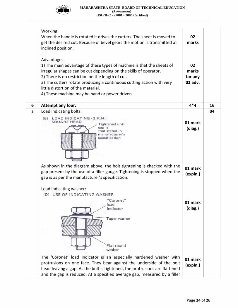
a Load indicating bolts:
As shown in the diagram above, the bolt tightening is checked with the gap present by the use of a filler gauge. Tightening is stopped when the gap is as per the manufacturer’s specification. Load indicating washer:
The ‘Coronet’ load indicator is an especially hardened washer with protrusions on one face. They bear against the underside of the bolt head leaving a gap. As the bolt is tightened, the protrusions are flattened and the gap is reduced. At a specified average gap, measured by a filler
01 mark (diag.)
01 mark (expln.)
01 mark (diag.)
01 mark (expln.)
04
MAHARASHTRA STATE BOARD OF TECHNICAL EDUCATION (Autonomous)
gauge, the induced shank tension should not be less than the minimum required by standards.
b The steps in folding a sheet metal job are: 1) Clamping: In clamping, the amount of lift of the clamping beam is
important. It should be sufficient to allow the fitting and use of special clamping blades or to give adequate clearance for previous folds.
2) Folding: Care must be taken to see that the folding beam will clear the work, particularly when making second or third folds. Some folding machines are designed to fold radii above the minimum, either by the fitting of a radius bar or by adjustment of the folding beam.
3) Removal of the work: Care must be taken in folding to ensure that the work may be easily removed on completion of final board. The sequence of folding must be carefully studied. The lift of the clamping beam is important here.
011/2 mark
011/2 marks
01 mark
04
c Blanking: It is the operation of cutting of flat sheet to the desired shape. The metal punched out is the required product and the plate with the hole left on the die goes as waste. The die governs the size of the blank produced and clearance is left on the punch. Piercing: It is the operation of production of a hole in a sheet metal by the punch and die. The material punched out to form the hole constitutes the waste. The punch governs the size of the hole (punch point diameter is less than or equal to material thickness) and clearance is provided on die.
02 mark
02 mark
04
d
Parameters Reciprocating Power Hacksaw
Bench Saw
Cost of machine High capital
investment Low capital
investment.
Sawing time Less time More time
Labor skill Semi-skilled. Unskilled
011/2
marks
011/2
mark
01 mark
04
MAHARASHTRA STATE BOARD OF TECHNICAL EDUCATION (Autonomous)
e Technique of starting a cut away from the edge (or procedure for burning a hole)
02 marks
for sketches
And
02
marks (for the points as in
sketch)
04
f Effect of clearance and rake angle on blades: Rake Angle: The shear blades are provided with a rake angle of 30(approx.) and an optimum rake angle enables the blades to dig into the material, thereby subjecting the internal fibres of the metal to plastic deformation prior to shearing. Too much of the rake angle weaken the blades and too less a rake angle requires more force to initiate plastic deformation. Clearance: There must be sufficient clearance between the cutting edges of the blades to help in the cutting action. An approximate rule is that the clearance should not exceed 10% of the thickness to be cut and must be varied to suit the particular material.