MAHARASHTRA STATE BOARD OF TECHNICAL EDUCATION (Autonomous) (ISO/IEC - 27001 - 2005 Certified) Summer – 15 EXAMINATION Subject Code: 17428 Model Answer Page 1/ 25 Important Instructions to examiners: 1) The answers should be examined by key words and not as word-to-word as given in the model answer scheme. 2) The model answer and the answer written by candidate may vary but the examiner may try to assess the understanding level of the candidate. 3) The language errors such as grammatical, spelling errors should not be given more Importance (Not applicable for subject English and Communication Skills. 4) While assessing figures, examiner may give credit for principal components indicated in the figure. The figures drawn by candidate and model answer may vary. The examiner may give credit for any equivalent figure drawn. 5) Credits may be given step wise for numerical problems. In some cases, the assumed constant values may vary and there may be some difference in the candidate‟s answers and model answer. 6) In case of some questions credit may be given by judgement on part of examiner of relevant answer based on candidate‟s understanding. 7) For programming language papers, credit may be given to any other program based on equivalent concept. Q.1. a) Attempt any six of the following: 12 i. Write any two modes of operation of CPU. Also mention one effect of each. (Any Two 1M each) Processor modes refer to the various operating environment that affect the instructions and capabilities of the chip. The processor mode controls how the processor sees and manages the system memory and the tasks that use it. Different Modes of operation 1. Real Mode (16 bit software): These 16 bit operating systems and applications are designed to run on original 8088 processor. The 16 bit instruction mode of 8088 is called the real mode. 2. IA -32 Mode: It has multi tasking capabilities. It has backward compatibility to run 16 bit OS and applications without any modification - Protected mode (32 bit software) - Virtual real mode (16 bit program within 32 bit environment) 3. IA 32 e – 64 bit extension mode: When DOS prompt is created within windows, virtual real mode is created. Several real mode sessions can be run each having its own software on a virtual PC. - 64 bit mode (64 bit software) - Compatibility mode ii. Write any four recording techniques. (any four, ½ M each) 1. FM (Frequency Modulation) 2. MFM(Modified Frequency Modulation) 3. RLL (Run Length Limited). 4. Perpendicular Recording
Transcript
MAHARASHTRA STATE BOARD OF TECHNICAL EDUCATION (Autonomous)
(ISO/IEC - 27001 - 2005 Certified)
Summer – 15 EXAMINATION
Subject Code: 17428 Model Answer Page 1/ 25
Important Instructions to examiners:
1) The answers should be examined by key words and not as word-to-word as given in the
model answer scheme.
2) The model answer and the answer written by candidate may vary but the examiner may try
to assess the understanding level of the candidate.
3) The language errors such as grammatical, spelling errors should not be given more
Importance (Not applicable for subject English and Communication Skills.
4) While assessing figures, examiner may give credit for principal components indicated in the
figure. The figures drawn by candidate and model answer may vary. The examiner may give credit for any
equivalent figure drawn.
5) Credits may be given step wise for numerical problems. In some cases, the assumed constant
values may vary and there may be some difference in the candidate‟s answers and model answer.
6) In case of some questions credit may be given by judgement on part of examiner of relevant answer based
on candidate‟s understanding.
7) For programming language papers, credit may be given to any other program based on equivalent
concept.
Q.1.
a) Attempt any six of the following: 12
i. Write any two modes of operation of CPU. Also mention one effect of each.
(Any Two 1M each)
Processor modes refer to the various operating environment that affect the instructions
and capabilities of the chip. The processor mode controls how the processor sees and
manages the system memory and the tasks that use it.
Different Modes of operation
1. Real Mode (16 bit software): These 16 bit operating systems and applications are
designed to run on original 8088 processor. The 16 bit instruction mode of 8088 is called
the real mode.
2. IA -32 Mode: It has multi tasking capabilities. It has backward compatibility to run 16
bit OS and applications without any modification
- Protected mode (32 bit software)
- Virtual real mode (16 bit program within 32 bit environment)
3. IA 32 e – 64 bit extension mode: When DOS prompt is created within windows,
virtual real mode is created. Several real mode sessions can be run each having its own
software on a virtual PC.
- 64 bit mode (64 bit software)
- Compatibility mode
ii. Write any four recording techniques. (any four, ½ M each)
1. FM (Frequency Modulation)
2. MFM(Modified Frequency Modulation)
3. RLL (Run Length Limited).
4. Perpendicular Recording
MAHARASHTRA STATE BOARD OF TECHNICAL EDUCATION (Autonomous)
(ISO/IEC - 27001 - 2005 Certified)
Summer – 15 EXAMINATION
Subject Code: 17428 Model Answer Page 2/ 25
iii. Write two advantages and two disadvantages of LCD monitor.
Advantages: (1/2 M each, any two)
1. Light weight; can be about 15 lbs for a thin LCD. Smaller footprint on desk leaving,
freeing up the work area on the user‟s desk.
2. Low frequency radiation is practically eliminated
3. Energy efficient, they do not generate heat.
4. Potentially less eyestrain due to reduced screen glare.
Disadvantages: (1/2 M each, any two)
1. Designed only for one optimum resolution; cannot adjust images.
2. There can be pixel defects in LCD panels.
3. LCD has smaller viewing angle and at larger viewing angle the image quality is poor.
4. The colour reproduction is poor in LCD.
iv. Write four types of key switches used in keyboard. ( any four, ½ M each)
Types of Key switches
1. Capacitive switch
2. Hall effect switch
3. Opto-electronic switch
4. Membrane switch
5. Mechanical switch
6. Rubber dome switch
v. Write two advantages and two disadvantages of Opto-mechanical mouse.
Advantages: (1/2 M each, any two point)
1. Its uses photo detector and LED for finding movement of mouse.
2. It requires less Maintenance.
3. It has few mechanical parts so life of mouse is less compare to Mechanical Mouse.
Disadvantages: (1/2 M each, any two point)
1. Its require cleaning of mouse.
2. They required special surface such as mouse pad.
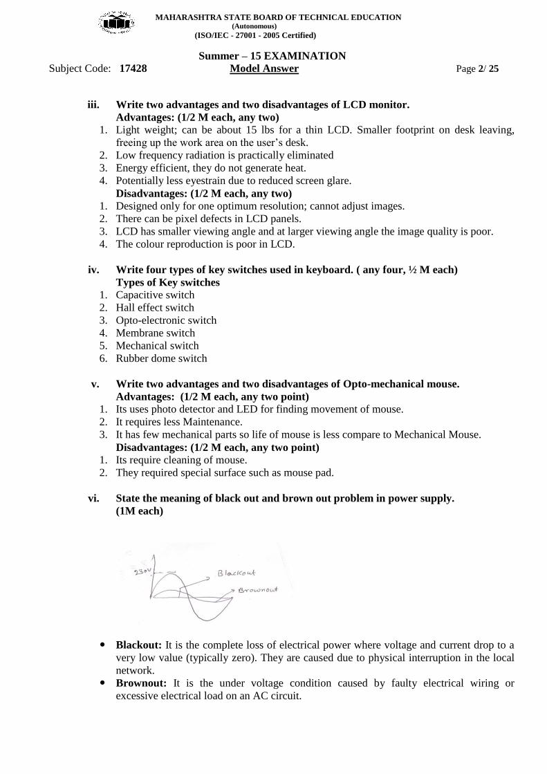
vi. State the meaning of black out and brown out problem in power supply.
(1M each)
Blackout: It is the complete loss of electrical power where voltage and current drop to a
very low value (typically zero). They are caused due to physical interruption in the local
network.
Brownout: It is the under voltage condition caused by faulty electrical wiring or
excessive electrical load on an AC circuit.
MAHARASHTRA STATE BOARD OF TECHNICAL EDUCATION (Autonomous)
(ISO/IEC - 27001 - 2005 Certified)
Summer – 15 EXAMINATION
Subject Code: 17428 Model Answer Page 3/ 25
vii. Write any four important features of USB port. (Any four, 2M)
1. Up to 127 different devices can be connected on a single USB bus.
2. Initial USB standard supported 12 Mbps transfer rate. Currently 60 Mbps is supported.
3. Supports wide range of peripherals such as keyboard, mouse, printer, FDD, game pad,
joystick etc.
4. Each device is connected to USB hub, which is an intelligent device interacting with the PC
on one side and USB peripheral devices on the other side.
5. The CPU/software initiates every transaction on the USB bus. Hence the over head on the PC
software increases.
viii. Write two advantages and two disadvantages of Bluetooth.
Advantages: (1/2 M each, any two)
1. Bluetooth does not require a clear line of sight between the synced devices.
2. Bluetooth transfers data at the rate of 1 Mbps, which is from three to eight times the
average speed of parallel and serial ports, respectively.
3. Bluetooth technology is designed to have very low power consumption
4. Bluetooth is extremely secure in that it employs several layers of data encryption and user
authentication measures
Disadvantages: (1/2 M each, any two)
1. The real-time data transfer usually not possible above 100m range.
2. Bluetooth only connect 8 devices simultaneously.
b) Attempt any TWO of the following: 8
i. Explain the terms extended memory and expanded memory with suitable example.
(Diagram 2M, Explanation 2M)
Extended Memory
It is the memory beyond 1 MB limit. Any memory available after 1 MB is called extended
memory. It is available in 286 and later processors only. Extended memory is of no use for
DOS users because DOS does not use this memory. For windows users this memory is
very useful as the OS can use this extended memory by allowing multiple DOS programs
to run in the extended memory in its own 640 KB memory area.
Expanded Memory
It is a specification which defines a method to access system memory above 1 MB of
RAM on PC XT and AT computers. This memory is accessed via 16 KB window with in
the first 1 MB. Expanded memory is not a part of main memory, it is separately installed
into the system which can be accessed in fixed size pages using a method called „bank
switching‟ In this method a small window located in the upper memory area in the main
memory is used to view the contents of EMS(Expanded Memory Specification).
The EMS is arranged in the blocks of 16KB each. To access this memory one block is
copied in the window in main memory and after processing it is copied back to the EMS
memory.
MAHARASHTRA STATE BOARD OF TECHNICAL EDUCATION (Autonomous)
(ISO/IEC - 27001 - 2005 Certified)
Summer – 15 EXAMINATION
Subject Code: 17428 Model Answer Page 4/ 25
ii. Explain the following
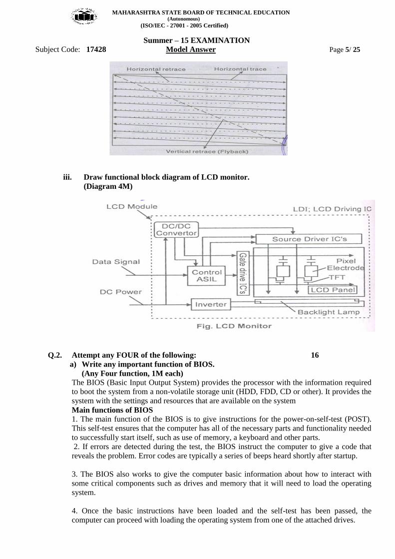
1) Interlaced scanning
2) Non interlaced scanning
(2M each scanning, 1M for Diagram, 1M explanation)
1) Interlaced scanning:
A interlace displays draws an image as two passes. Once the first pass is complete a second
pass fills in the rest of the image.
In order to avoid a flickering image, some adapters force the monitor to create an interlaced
image.
Instead of the electron gun scanning from top to bottom in a continuous manner, on the first
pass it will skip every next line.
On the second pass, it will scan the lines that it skipped during the first pass, thus creating full
image in two scans instead of one.
The odd raster starts at the top left edge and the even raster at the middle of the CRT.
This scanning process skips every next line, results in a maximum of 525 vertical lines.
Screen flicker is much more noticeable.
Also the effective refresh is less.
2) Non interlaced scanning:
A non interlaced monitor draws all of the lines that compose an image in one pass
The entire image is first refreshed at the vertical scanning frequency.
The effective image refresh rate is only half the stated vertical scanning rate.
MAHARASHTRA STATE BOARD OF TECHNICAL EDUCATION (Autonomous)
(ISO/IEC - 27001 - 2005 Certified)
Summer – 15 EXAMINATION
Subject Code: 17428 Model Answer Page 5/ 25
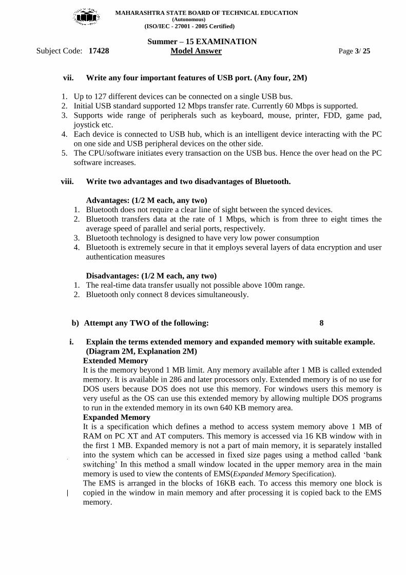
iii. Draw functional block diagram of LCD monitor.
(Diagram 4M)
Q.2. Attempt any FOUR of the following: 16
a) Write any important function of BIOS.
(Any Four function, 1M each)
The BIOS (Basic Input Output System) provides the processor with the information required
to boot the system from a non-volatile storage unit (HDD, FDD, CD or other). It provides the
system with the settings and resources that are available on the system
Main functions of BIOS
1. The main function of the BIOS is to give instructions for the power-on-self-test (POST).
This self-test ensures that the computer has all of the necessary parts and functionality needed
to successfully start itself, such as use of memory, a keyboard and other parts.
2. If errors are detected during the test, the BIOS instruct the computer to give a code that
reveals the problem. Error codes are typically a series of beeps heard shortly after startup.
3. The BIOS also works to give the computer basic information about how to interact with
some critical components such as drives and memory that it will need to load the operating
system.
4. Once the basic instructions have been loaded and the self-test has been passed, the
computer can proceed with loading the operating system from one of the attached drives.
MAHARASHTRA STATE BOARD OF TECHNICAL EDUCATION (Autonomous)
(ISO/IEC - 27001 - 2005 Certified)
Summer – 15 EXAMINATION
Subject Code: 17428 Model Answer Page 6/ 25
5. Computer users can often make certain adjustments to the BIOS through a configuration
screen on the computer. The setup screen is typically accessed with a special key sequence
during the first moments of the startup. This setup screen often allows users to change the
order in which drives are accessed during startup and control the functionality of a number of
critical devices. Features vary among individual BIOS versions.
6. Many PC manufacturers today use flash memory cards to hold BIOS information. This
allows users to update the BIOS version on computers after a vendor releases an update. This
system was designed to solve problems with the original BIOS or to add new functionality.
Users can periodically check for updated BIOS versions, as some vendors release a dozen or
more updates over the course of a products lifetime. To check for updated BIOS, users can
check the website of the specific hardware vendor.
b) Explain the following with the help of neat diagram:
i. Track
ii. Sector
iii. Cylinder
iv. Cluster
(Explanation 1M each)
i. Track
Each side of HDD platter‟s surface is divided into concentric circles called tracks
They are magnetic information written during formatting of HDD
Outermost track is called track 0. The innermost will have the highest number
ii. Sector:
A track is a big area to store data (5000 bytes). Hence tracks are divided into sectors
The formatting program divides disk surface into sectors by writing magnetic pattern on
disk surface
Different HDD capacities have different number of tracks
512 byte data can be stored in each sector. Sector no. starts from 1
iii. Cylinder
Same tracks of different platters form an imaginary cylinder like structure
Data is stored cylinder by cylinder
All tracks on a cylinder are written and then the R/W head moves to the next cylinder. This
reduces movement of R/W head and increases the speed of read and write operation
MAHARASHTRA STATE BOARD OF TECHNICAL EDUCATION (Autonomous)
(ISO/IEC - 27001 - 2005 Certified)
Summer – 15 EXAMINATION
Subject Code: 17428 Model Answer Page 7/ 25
iv. Cluster
When OS writes some information on the hard disk, it does not allocate the space sector
wise, instead uses a new unit of storage called “Cluster”
Clusters are the minimum space allocated by DOS when storing any information on the
disk
Even to store only one byte long information on the disk requires minimum one cluster
area on the disk surface
A cluster can be made up of one or more sectors; it depends on disk type being used.
This reduces the size of FAT that DOS uses to keep track of the used and the empty disk
space
First cluster no. is taken as 2
Clusters are used to allocate the storage area for data area only, FAT and directory areas
are not allocated according to the cluster size
c) Draw and explain block diagram of CD drive.
(2-marks for Diagram, 2-marks for Explanation)
A CD drive consists of
1. Optical head which contains laser diode, photo detector and beam splitter
2. Drive controller
MAHARASHTRA STATE BOARD OF TECHNICAL EDUCATION (Autonomous)
(ISO/IEC - 27001 - 2005 Certified)
Summer – 15 EXAMINATION
Subject Code: 17428 Model Answer Page 8/ 25
3. Loading mechanism
4. Servo motor
5. I/O interface
Construction:
The optical head contains:
1. Laser diode, which generates the laser beam
2. A lens system to focus the laser beam on the disc and to direct the reflected beam on to
the photo detector. The beam spitter sends the reflected beam towards a different lens for
focusing.
3. Servo motors that control the position of laser and lenses to ensure correct tracking and
focusing.
4. Photo detector that detects the reflected light and converts it into electric pulses.
Drive controller is the overall controller of the CD drive. It controls the speed of rotation
and processes the signals coming from the optical head.
The information coming from the photo detector is in the encoded from (8 to 14
Modulation) (EFM). The decoding of data is done by the microprocessor on the
controller.
The decoded data is sent to the I/O interface, which makes it available to the system.
d) Distinguished between FAT-32 and NTFS.(Any 8 Points, ½ M each)
Criteria NTFS
FAT 32
OS Windows 2000, XP, 2003
server
DOS V7, Win 2000,98,XP
Maximum Volume
Size
2TB 32GB
Max. Files on
Volume
Unlimited 4194304
Max file size Limited by volume size 4GB
Max Cluster
number
Unlimited 4177918
Boot sector location 1st and last
First sector and copy in sector No
6
Compression Yes NO
Built in security Yes NO
Recoverability Yes NO
performance High on large volume
Low on small volume
Good on small volume, Low on
large
Security Folder and fie access can be
controlled individually
Very little
Compatibility
Not compatible with window
95/98/Me
Compatible with all OS (32 bit)
Space efficiency Supports disk quotas to
control amount of disk space
per user
Does not support disk quota
MAHARASHTRA STATE BOARD OF TECHNICAL EDUCATION (Autonomous)
(ISO/IEC - 27001 - 2005 Certified)
Summer – 15 EXAMINATION
Subject Code: 17428 Model Answer Page 9/ 25
e) Write any four important characteristics of colour CRT monitor.
(Any Four; Explanation 1M each)
Dot pitch: It is the distance between each group (triad) of red, blue and green phosphors.
A smaller dot pitch helps produce sharper and clearer image
Resolution: Resolution describes the number of potential pixels the monitor is capable of
displaying.
Resolution = Total Horizontal Pixels x Total vertical pixels
Video bandwidth: • It is the highest input frequency a monitor can handle and helps in determining the
resolution capabilities of the monitor.
• The video bandwidth is measured in MHz.
• Higher the video bandwidth, better the image quality.
• Video Bandwidth = Horizontal. Pixel X Vertical. Pixel X Frame rate
Horizontal scanning:
Scanning of the electron beam on the screen of the monitor is called raster scanning. The
tracing of the horizontal lines in synchronism with H – Sync pulse is called Horizontal
Scanning
f) Draw and explain the block diagram of external modem.
(Definition – ½ Marks Diagram – 2 Marks, Explanation- 1½ Marks)
Definition: Modem is a device used to convert the analog signals to digital and digital signals
to analog.
Diagram:
Explanation:
The external modem does not include built in UART. It uses existing serial port already
configured in the PC.
A 9 pin (DB9) or 25 pin serial cables connects the PC serial port to the modem. Thus CPU
need not be opened during modem installation.
A modulator circuit converts serial data into audio signal.
The modulated audio signal is coupled to the Telephone lines by telephone interface.
MAHARASHTRA STATE BOARD OF TECHNICAL EDUCATION (Autonomous)
(ISO/IEC - 27001 - 2005 Certified)
Summer – 15 EXAMINATION
Subject Code: 17428 Model Answer Page 10/ 25
Audio signal is passing through RJ 11 type connector at the rear of the modem to the
telephone lines where signal receives from the telephone lines must be translated back into
serial data.
The signal receives from telephone lines are converted into digital information using
demodulator.
The controller circuit manages the overall operation of the modem by switching the modem
between its control and data operating mode.
During power loss or reset condition default modem parameters can be loaded from NV
RAM. Permanent changes to modem parameters are stored in NVRAM.
External modems avoid hardware conflicts such as (conflict of I/O address lines and that of
interrupt lines) the external modem setup is faster and easier than internal modems.
In the external modem the status of serial communication can be checked from the signal
status LEDs.
Q.3. Attempt any FOUR of the following: 16
a) Describe the CMOS setup. State any two importance of CMOS setup. (Description – 3M; Importance – 1M) During booting by pressing a function key F2 or del key CMOS (Complementary Metal Oxide
Semiconductor) Set up utility is used in a PC to set up the basic properties of a computer as given
below.
Standard CMOS Setup: It is used to set time date, hard disk type, type of floppy drive, type
of monitor and keyboard.
Advanced CMOS Setup: It is used to set typematic rate and delay, above 1 MB memory
test, memory test tick sound, Hil < Del> message display, system boot up sequence etc.
Advanced Chipset Setup: It is used to set features of chipset.
Power Management Setup: It is used to control power conservation options.
PCI/Plug and Play Setup: It is used to set options of PCI bus and that of plug and play
devices.
Peripherals Setup: It is used to control options related to I/O controllers.
CPU Configuration Setup: This setup is used to select the types of CPU installed in the
motherboard. In AMI BIOS, the setting automatically finds out the type of CPU in the
computer system. Importance:
1. Used to set date and time, which in turn can be helpful to keep the system up-to-date.
2. Setting up various peripheral automatically or manually.
3. Enable or disable the devices used in the system.
4. Stores information that is updated
b) State the difference between touch screen monitor and normal LCD monitor. (Any four difference – each 1M ; Any other suitable difference may be considered.)
Touch screen monitors are capable of reading signals and transport it to processing unit, whereas LCD
monitors are used to display the images.
Types of Touch screens depend upon the material used for the sensitivity of the screen, whereas LCD
monitors are classified based on which technology is used for the display
MAHARASHTRA STATE BOARD OF TECHNICAL EDUCATION (Autonomous)
(ISO/IEC - 27001 - 2005 Certified)
Summer – 15 EXAMINATION
Subject Code: 17428 Model Answer Page 11/ 25
In the construction of Touch screen, more number of layers are present on the LCD layer, when
compared to LCD Monitor.
Touch Screens are interactive and hence more expensive than the normal LCD screens used only as
output device.
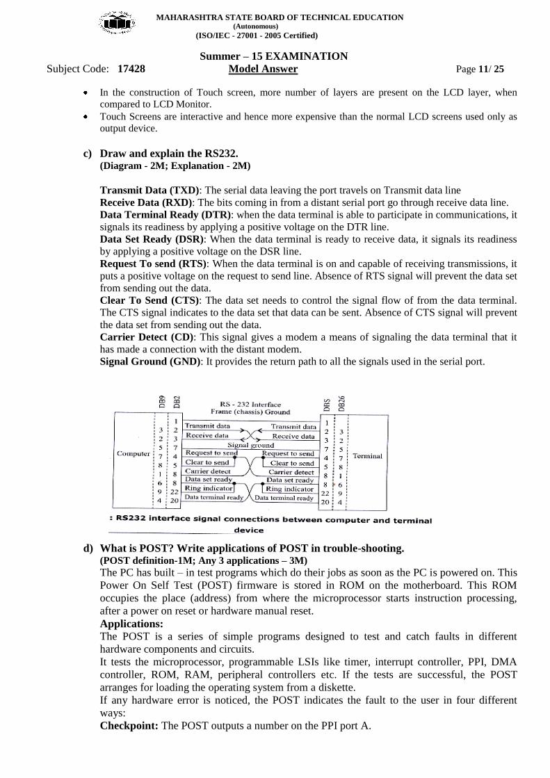
c) Draw and explain the RS232. (Diagram - 2M; Explanation - 2M)
Transmit Data (TXD): The serial data leaving the port travels on Transmit data line
Receive Data (RXD): The bits coming in from a distant serial port go through receive data line.
Data Terminal Ready (DTR): when the data terminal is able to participate in communications, it
signals its readiness by applying a positive voltage on the DTR line.
Data Set Ready (DSR): When the data terminal is ready to receive data, it signals its readiness
by applying a positive voltage on the DSR line.
Request To send (RTS): When the data terminal is on and capable of receiving transmissions, it
puts a positive voltage on the request to send line. Absence of RTS signal will prevent the data set
from sending out the data.
Clear To Send (CTS): The data set needs to control the signal flow of from the data terminal.
The CTS signal indicates to the data set that data can be sent. Absence of CTS signal will prevent
the data set from sending out the data.
Carrier Detect (CD): This signal gives a modem a means of signaling the data terminal that it
has made a connection with the distant modem.
Signal Ground (GND): It provides the return path to all the signals used in the serial port.
d) What is POST? Write applications of POST in trouble-shooting. (POST definition-1M; Any 3 applications – 3M)
The PC has built – in test programs which do their jobs as soon as the PC is powered on. This
Power On Self Test (POST) firmware is stored in ROM on the motherboard. This ROM
occupies the place (address) from where the microprocessor starts instruction processing,
after a power on reset or hardware manual reset.
Applications:
The POST is a series of simple programs designed to test and catch faults in different
hardware components and circuits.
It tests the microprocessor, programmable LSIs like timer, interrupt controller, PPI, DMA
controller, ROM, RAM, peripheral controllers etc. If the tests are successful, the POST
arranges for loading the operating system from a diskette.
If any hardware error is noticed, the POST indicates the fault to the user in four different
ways:
Checkpoint: The POST outputs a number on the PPI port A.
MAHARASHTRA STATE BOARD OF TECHNICAL EDUCATION (Autonomous)
(ISO/IEC - 27001 - 2005 Certified)
Summer – 15 EXAMINATION
Subject Code: 17428 Model Answer Page 12/ 25
Beep method: The POST causes different tones (Long & Short) at the speaker.
Error Code: An error code is displayed on the CRT.
Error Message: The POST displays a detailed error message which identifies the problem
area.
e) Explain active and passive maintenance with suitable example. (Explanation of AM and PM each 1M; Example 1M)
Two Type of Maintenance Active and Passive
It describes several procedures to clean and lubricate all the major components, cleaning all
boards, connectors, contacts etc. It also describes similar procedures for different peripheral
devices such as HDD, FDD, keyboard, printer, monitor etc. It includes performing backups,
antivirus and antispyware scans.
Active preventive maintenance includes
i) Regular cleaning of the system using cleaning tools & cleaning solutions
ii) Preventive maintenance of the system, which are either weekly or monthly.
Weekly maintenance includes
Backup of important data
Deleting temporary files
Empty recycle bin
Check for antivirus software updates
Run defragmentation program
Monthly maintenance includes,
Create a startup disk
Check for updated drivers
O.S. updates
Cleaning the drivers
Passive preventive maintenance (1 mark)
It involves taking care of the system from physical environment and electrical problems.
Physical conditions such as temperature, thermal stress, dust and smoke contamination and
shock and vibration.
Electrical issues such as ESD (Electro Static Discharge), power line noise and RFI (Radio
frequency interference)
Physical contributors to system failure (Any three 1 mark each)
1. Dust and pollutants
The power supply fan carries air borne particles through your system and they collect inside
the system.
Prevention of dust and dirt
Use dust covers when not in use.
Use curtains on windows
Use air conditioners for computer room.
Avoid shoes into computer room.
Avoid smoking near a PC.
Use vacuum cleaner to clean the surrounding area of the PC frequently.
MAHARASHTRA STATE BOARD OF TECHNICAL EDUCATION (Autonomous)
(ISO/IEC - 27001 - 2005 Certified)
Summer – 15 EXAMINATION
Subject Code: 17428 Model Answer Page 13/ 25
2. Excessive temperature
Thermal expansion and contraction from excessive temperature changes places thermal stress
on the system. To avoid this temperature in the room must remain relatively constant. There
are two conditions of excessive temperature: Heat and Cold
Excessive heat leads to
Breaking of solder joints.
Damage of solid state components.
Accelerated corrosion of contacts in the system
Cracking of circuit boards.
Problems with hard disk as the metallic components expand.
Prevention
Keep the cooling vents clear.
Keep the system dust free from inside and outside.
Keep the disks in cool dry location.
Install air conditioners to maintain the room temperature.
Effect of Cold
Due to cold the resistance of electronic components decreases and the component will take
very large current when the system is switched on.
Low temperatures affect the mechanical components of the FDD.
The floppy disk becomes brittle.
Prevention
Use room heater to maintain the room temperature.
3. Corrosion
It is a chemical process in which metal coating of pins and sockets is gradually oxidized.
Corrosion Effects
Types
Direct oxidation: In this a film of oxide is formed on the metal surface. The metal film acts
as an insulator and creates contact problems.
Atmospheric corrosion: It causes rusting and reduces the electrical contact between the
components.
Galvanic corrosion: Moisture borne electrolyte enters through a tiny crack or hole in the
metal plating and causes corrosion.
Prevention
Periodic cleaning.
Clean the pins of ICs and connectors.
Use organic solvent for cleaning the oxide layer and corroded contacts.
4. Magnetic Effect
Magnets both permanent and electromagnetic type can cause permanent loss of data on the
hard disk.
In office electromagnetism can be produced by electric motors.
The voltages used in monitor and television receiver are sources of strong magnetic fields.
Other sources of magnetism:
Paper clip holder with a magnet, stereo speakers, Magnetic screw extractor, metal
detectors etc
Prevention
To avoid data loss due to magnetism, keep disks and information cables away from the
magnets.
MAHARASHTRA STATE BOARD OF TECHNICAL EDUCATION (Autonomous)
(ISO/IEC - 27001 - 2005 Certified)
Summer – 15 EXAMINATION
Subject Code: 17428 Model Answer Page 14/ 25
Electrical contributors to system failure
1. ESD (Electro Static Discharge)
This problem usually arises in winter when the humidity is low. Our body can accumulate
static charges up to 25,000V. When we touch any component in the PC the accumulated
static charge will discharge to ground. This can damage the component.
Prevention
Before touching any component we must discharge any accumulated potential to ground.
This can be done by touching the ground area of the system.
Use ground strap attached around your wrist. The other end of the strap is connected to the
system ground.
Use anti static mat
Do not wear synthetic clothes.
The system should have good power line grounding.
2. Power line noise
A computer system should have steady supply of noise free power.
The circuit should be checked for good low resistance ground, proper line voltage, free
from interference and brownouts.
Three pin socket is a must.
Power line noise problem increases with wire size and length.
Prevention
Isolation, Shielding, Power grounding.
3. Radio Frequency interference (RFI)
It is caused by any source of radio transmission near a PC. It is high frequency radiation (freq
> 10 Khz).
Sources of RFI
High speed digital Circuits, nearby radio source, Cordless telephones, Mobile phones,
motors, Power line intercoms.
Prevention
Put all the sources which can produce RFI away from the PC.
f) State and interpret the meaning of beep codes. (Any four beep codes and interpretation – each 1M.)
Any other 4 beep codes such as for AWARD may also be considered.
For IBM PCs
Beep Code Description
No Beeps No Power, Loose Card, or Short.
1 Short Beep Normal POST, computer is ok.
2 Short Beep POST error, review screen for error code.
Continuous Beep No Power, Loose Card, or Short.
Repeating Short Beep No Power, Loose Card, or Short.
One Long and one Short Beep Motherboard issue.
One Long and Two Short Beeps Video (Mono/CGA Display Circuitry) issue.
One Long and Three Short Beeps. Video (EGA) Display Circuitry.
Three Long Beeps Keyboard or Keyboard card error.
One Beep, Blank or Incorrect Display Video Display Circuitry.
MAHARASHTRA STATE BOARD OF TECHNICAL EDUCATION (Autonomous)
(ISO/IEC - 27001 - 2005 Certified)
Summer – 15 EXAMINATION
Subject Code: 17428 Model Answer Page 15/ 25
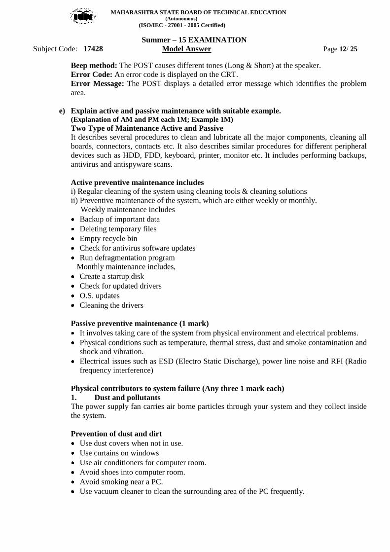
For AMIBIOS
Beep Code Descriptions
1 short DRAM refresh failure
2 short Parity circuit failure
3 short Base 64K RAM failure
4 short System timer failure
5 short Process failure
6 short Keyboard controller Gate A20 error
1 long, 3 short Conventional/Extended memory failure
1 long, 8 short Display/Retrace test failed
two-tone siren Low CPU Fan speed, Voltage Level issue
Q.4. Attempt any FOUR of the following: 16
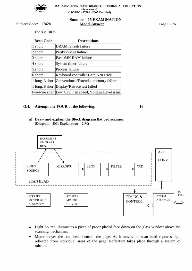
a) Draw and explain the Block diagram flat bed scanner. (Diagram - 2M; Explanation – 2 M)
Light Source illuminates a piece of paper placed face down on the glass window above the
scanning mechanism.
Motor moves the scan head beneath the page. As it moves the scan head captures light
reflected from individual areas of the page. Reflection takes place through a system of
mirrors.
DOCUMENT
ON GLASS
BED
CCD LIGHT
SOURCE
MIRRORS LENS FILTER
STEPPER
MOTOR
DRIVER
STEPPER
MOTOR BELT ASSEMBLY
A-D
CONV
SCAN HEAD
TIMING &
CONTROL
SYSTEM
INTERFACE
PC
PORT
MAHARASHTRA STATE BOARD OF TECHNICAL EDUCATION (Autonomous)
(ISO/IEC - 27001 - 2005 Certified)
Summer – 15 EXAMINATION
Subject Code: 17428 Model Answer Page 16/ 25
A lens focuses the beams of light on to light sensitive diodes that translate the amount of light
into electrical current.
The more the reflected light, the more is the voltage of the signal. White spaces reflect more
light than black or colored images.
ADC converts each analog signal of voltage into digital pixel representing the scanned area.
For monochrome scanner 1 bit per pixel is stored either on or off representing black or white.
For color scanner, the scan head makes three passes under the images and the light on each
pass is directed through a red, green or blue filter before it strikes the original image. Signals
from three passes are converted into digital information and stored to represent red, green, or
blue color value of the scanned area on the page.
This digital information is sent to the software in the PC, where data is stored in a format on
which a graphics program or OCR can work.
b) Write any four important characteristics of Dot Matrix Printers.
(Each Characteristics 1M)
Dot Matrix characteristics:
It is an impact printer, where printer head touches the paper with an inked ribbon
The quality of the image is determined by the dots per inch.
Its speed is measured with respect to characters per second(cps)
It‟s quality of printing is not as good as other non impact printers
The Mechanical movements are more when compared to other printer and also noisy.
Most of the Dot Matrix printers are with parallel ports (Centronics)
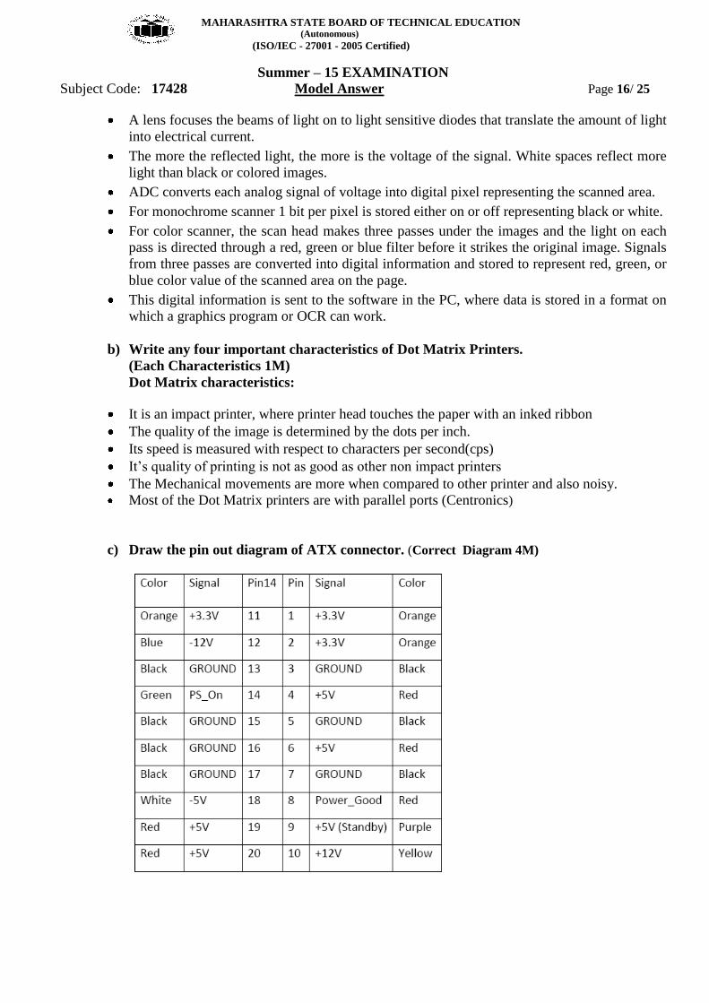
c) Draw the pin out diagram of ATX connector. (Correct Diagram 4M)
MAHARASHTRA STATE BOARD OF TECHNICAL EDUCATION (Autonomous)
(ISO/IEC - 27001 - 2005 Certified)
Summer – 15 EXAMINATION
Subject Code: 17428 Model Answer Page 17/ 25
d) What are the symptoms of power supply problem? (Any four symptoms – each 1M)
Following are some of the situations that suggest power problems.
The lights tend to flicker or periodically vary in intensity.
The PC stalls, crashes or reboots for no apparent reason.
Chronic or frequent hard drive failure or file access problems.
The CMOS RAM or modem NVRAM periodically loses its contents or becomes corrupted.
The modem regularly loses its connection or fails data transfers.
The monitor display flickers or waves.
Frequent errors while writing data to the disk.
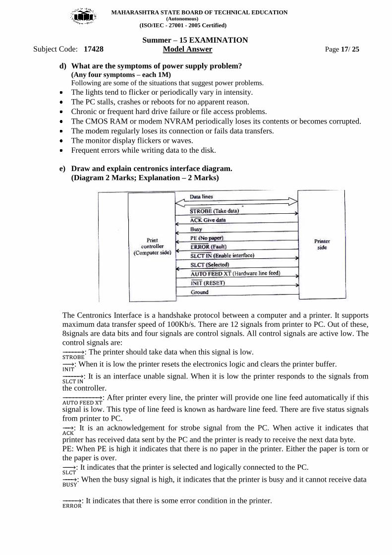
e) Draw and explain centronics interface diagram.
(Diagram 2 Marks; Explanation – 2 Marks)
The Centronics Interface is a handshake protocol between a computer and a printer. It supports
maximum data transfer speed of 100Kb/s. There are 12 signals from printer to PC. Out of these,
8signals are data bits and four signals are control signals. All control signals are active low. The
control signals are:
: The printer should take data when this signal is low.
: When it is low the printer resets the electronics logic and clears the printer buffer.
: It is an interface unable signal. When it is low the printer responds to the signals from
the controller.
: After printer every line, the printer will provide one line feed automatically if this
signal is low. This type of line feed is known as hardware line feed. There are five status signals
from printer to PC.
: It is an acknowledgement for strobe signal from the PC. When active it indicates that
printer has received data sent by the PC and the printer is ready to receive the next data byte.
PE: When PE is high it indicates that there is no paper in the printer. Either the paper is torn or
the paper is over.
: It indicates that the printer is selected and logically connected to the PC.
: When the busy signal is high, it indicates that the printer is busy and it cannot receive data
: It indicates that there is some error condition in the printer.
MAHARASHTRA STATE BOARD OF TECHNICAL EDUCATION (Autonomous)
(ISO/IEC - 27001 - 2005 Certified)
Summer – 15 EXAMINATION
Subject Code: 17428 Model Answer Page 18/ 25
f) Write any four firewire features.
Firewire is a serial interface for different high speed peripherals.
1. Hot pluggability.
2. Multiple devices up to 63.
3. Uses daisy chain topology
4. Data Transfer Rate 400/ 800 Mbps
5. Snap connection: no need for device ID, jumper, DIP switch, terminators etc.
6. Power sourcing.
7. Dynamic reconfiguration.
8. Max distance between devices: 4.5m
9. Supports DMA transfers
10. Well suited for different devices such as Digital Camera, Scanner, HDD, printers, music
systems
Q.5. Attempt any TWO of the following: 16
a) Write two important features of the following:
i. SDRAM
ii. DDR
iii. Cache
iv. DDR2
(Any two features 2 marks each)
(i) SDRAM:
1. Synchronous dynamic random access memory (SDRAM) is dynamic random access
memory (DRAM) that is synchronized with the system bus.
2. It waits for a clock signal before responding to control inputs and is therefore synchronized
with the computer's system bus.
3. Any byte of memory can be accessed without touching the preceding bytes.
4. SDRAM is volatile, meaning that they lose their contents when the power is turned off.
(ii) DDR:
1. DDR memory‟s primary advantage is the ability to fetch data on both the rising and falling
edge of a clock cycle, doubling the data rate for a given clock frequency.
2. Data Bus: 64 bits
3. Data Rate: 200/266/333/400MHz
4. Voltage: 2.5V
5. DRAM Frequency: 100/133/166/200Mhz.
(iii) Cache:
1. Runs at the same speed as the CPU/main memory. Typically runs at 66, 100,133 MHz.
2. Available in Sizes 8KB, 16 KB, 32KB, 64KB etc.
(iv) DDR2:
1. Data Bus: 64 bits
MAHARASHTRA STATE BOARD OF TECHNICAL EDUCATION (Autonomous)
(ISO/IEC - 27001 - 2005 Certified)
Summer – 15 EXAMINATION
Subject Code: 17428 Model Answer Page 19/ 25
2. Data Rate: 400/533/677Mhz
3. Voltage: 1.8V
4. DRAM Frequency: 200/266/333Mhz
b) Draw and explain the north and south bridge chipset architecture. (Diagram 4 Marks, Explanation 4 Marks)
Intel‟s earlier chipset were broken into multi-tired architecture known as North Bridge and
South Bridge components as well as Super I/O chip. North Bridge: it is the connection between
the high speed processor bus and the slower AGP & PCI buses. South Bridge: it is the bridge
between PCI bus and even slower ISA bus. Super I/O chip: contains commonly used peripheral
items all combined in single chip.
North Bridge Northbridge is also referred to as PAC (PCI-AGP) controller is the main component of the
motherboard and only motherboard circuit (besides the processor) that runs at the full
motherboard speed. It serves as the four way connection between CPU, Memory, Video card and
south bridge.
South Bridge The Southbridge is the lower speed component of the chipset. The south bridge connects to the
33MHz PC and contains the interface to ISA bus. It also contains dual ATA/IDE hard disk
controller interfaces, one or more USB interfaces, CMOS RAM, real time clock functions,
interrupt controller, DMA controller.
Super I/O chip contains serial port, floppy controller, keyboard & mouse interface.
MAHARASHTRA STATE BOARD OF TECHNICAL EDUCATION (Autonomous)
(ISO/IEC - 27001 - 2005 Certified)
Summer – 15 EXAMINATION
Subject Code: 17428 Model Answer Page 20/ 25
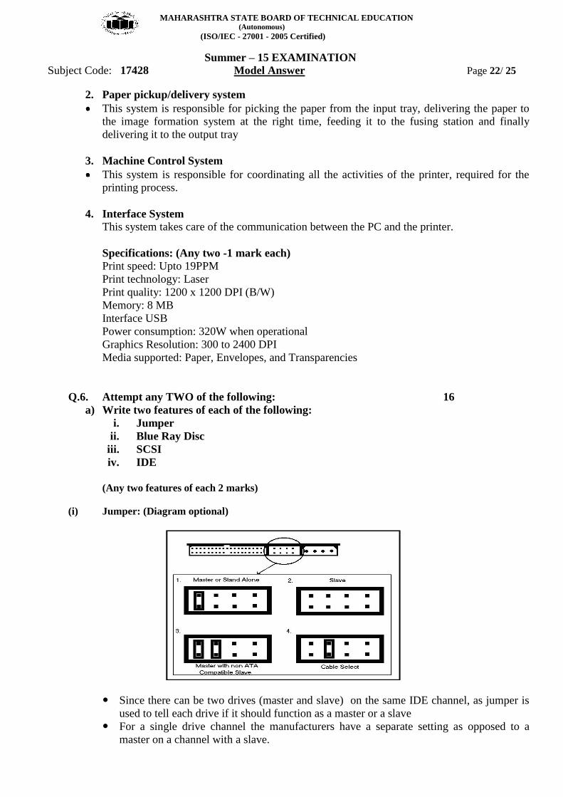
c) Draw and explain the Laser Printer block diagram and mention any two important