MAHARASHTRA STATE BOARD OF TECHNICAL EDUCATION (Autonomous) (ISO/IEC - 27001 - 2005 Certified) Important Instructions to examiners: 1) The answers should be examined by key words and not as word-to-word as given in themodel answer scheme. 2) The model answer and the answer written by candidate may vary but the examiner may tryto assess the understanding level of the candidate. 3) The language errors such as grammatical, spelling errors should not be given moreImportance (Not applicable for subject English and Communication Skills. 4) While assessing figures, examiner may give credit for principal components indicated in thefigure. The figures drawn by candidate and model answer may vary. The examiner may give credit for anyequivalent figure drawn. 5) Credits may be given step wise for numerical problems. In some cases, the assumed model answer. In case of some questions credit may be given by judgement on part of examiner of relevant s understanding. 7) For programming language papers, credit may be given to any other program based on equivalent concept. Answer: (Explanation 1 Mark, Figure 1 Mark) Isochoric process, also called a constant-volume process. It is a thermodynamic process during which the volume of the closed system undergoing such a process remains constant. An isochoric thermodynamic process is characterized by constant volume V = 0. Define: i) sensible heat ii) Latent heat Answer:(One mark each) i)Sensible heat: It is defined as the quantity of heat which can be sensed by the thermometer. OR The amount of heat added up to saturation temperature is called sensible heat. 1
Transcript
MAHARASHTRA STATE BOARD OF TECHNICAL EDUCATION (Autonomous)
(ISO/IEC - 27001 - 2005 Certified)
Important Instructions to examiners: 1) The answers should be examined by key words and not as word-to-word as given in
themodel answer scheme. 2) The model answer and the answer written by candidate may vary but the examiner may
tryto assess the understanding level of the candidate. 3) The language errors such as grammatical, spelling errors should not be given
moreImportance (Not applicable for subject English and Communication Skills. 4) While assessing figures, examiner may give credit for principal components indicated in
thefigure. The figures drawn by candidate and model answer may vary. The examiner may give credit for anyequivalent figure drawn.
5) Credits may be given step wise for numerical problems. In some cases, the assumed
model answer. In case of some questions credit may be given by judgement on part of examiner of relevant
s understanding.7) For programming language papers, credit may be given to any other program based on
equivalent concept.
Answer: (Explanation 1 Mark, Figure 1 Mark) Isochoric process, also called a constant-volume process. It is a thermodynamic process during which the volume of the closed system undergoing such a process remains constant. An isochoric thermodynamic process is characterized by constant volume V = 0.
Define: i) sensible heat ii) Latent heat Answer:(One mark each) i)Sensible heat: It is defined as the quantity of heat which can be sensed by the thermometer. OR The amount of heat added up to saturation temperature is called sensible heat.
1
MAHARASHTRA STATE BOARD OF TECHNICAL EDUCATION (Autonomous)
(ISO/IEC - 27001 - 2005 Certified)
ii)Latent heat: It is defined as the quantity of heat required for phase change of working substance at saturation temperature. OR The amount of heat added at saturation temperature is called latent heat. Latent heat is usually expressed in kJ/kg. Depending upon the change in state which a substance undergoes, different names have been given to this latent heat.
1
Define free air delivered and piston displacement related to air compressor. 2 Answer: Free Air Delivered (FAD): It is the actual volume of air delivered by the compressor when reduced to NTP. Piston Displacement:This is the volume swept by the piston in moving from T.D.C. to
piston displacement Vs is given by
1 1
State the application of compressed air. 2
Answer: Application of compressed air: (Any four ½ Mark each) 1. Operating tools in factories 2. Operating drills and hammers in road building 3. Starting diesel engines 4. Operating brakes on buses, trucks and trains 5. Spray painting 6. Excavating
2
Draw dual combustion cycle on P-V and T-S Diagram.
Answer: (P-V diagram 1 Mark, T-S diagram 1 Mark)
2
Define conventional and Non conventional energy sources.
Conventional sources of energy: These sources of energy are also called non renewable sources. These sources of energy are in limited quantity except hydro-electric power. Petrol, Diesel, Kerosene, Oil Non-conventional sources of energy: Energy generated by using wind, tides, solar, geothermal heat, and biomass including farm and animal waste as well as human
1 1
MAHARASHTRA STATE BOARD OF TECHNICAL EDUCATION (Autonomous)
(ISO/IEC - 27001 - 2005 Certified)
excreta is known as non-conventional energy. All these sources are renewable or inexhaustible and do not cause environmental pollution. More over they do not require heavy expenditure. Solar energy, Wind energy, Geothermal energy, Tidal energy,Biomass Define calorific value of fuel. 2 Answer: Calorific value of fuel It is defined as the amount of heat liberated during complete combustion of 1 kg of fuel. It is expressed in terms of KJ/kg. H.C.V. of Fuel: Higher calorific value of fuel is defined as amount of heat energy obtain by the complete combustion of 1kg of fuel, when the products of its combustion are cooled down to the temperature of supplied air. Unit is (KJ/kg) L.C.V. of Fuel: When heat absorbed or carried away by the product of combustion is not recovered & steam is formed during combustion is not condensed. Then the amount of
2
List the properties of fuel. 2
Answer: ( ½ Mark each property)(any four) 1. High calorific value 2. Moderate ignition temperature 3. Low moisture content 4. Low NOx combustible matter 5. Moderate velocity of combustion 6. Products of combustion not harmful 7. Low cost 8. Easy to transport 9. Combustion should be controllable 10. No spontaneous combustion 11. Low storage cost 12. Should burn in air with efficiency.
2
Attempt any TWO of the following 8
Draw Isobaric and Isothermal process on P-V and T-S Diagram. 4 Answer:( 2 Marks each process) Isobaric Process:
2
MAHARASHTRA STATE BOARD OF TECHNICAL EDUCATION (Autonomous)
(ISO/IEC - 27001 - 2005 Certified)
Isothermal Proces:
2
Describe the different phases of formation of steam. 4
Answer: (Explanation 2 Marks, Figure 2 Marks) Different phases of Formation of steam Consider formation of steam from ice at -200 C i)Solid phase- When the heat is added in ice which is at -20 0C, the temperature of ice increases to 00C as shown in figure by process A-B.in this stage solid phase exists. ii) Solid+ Liquid phase- The point B is called is saturation point when heat is further added this heat cannot increase the temperature but ice is converted into water that means phase transformation takes place, thus in-between region B-C, solid and liquid phase exists. iii) Liquid phase- From point further heat is added up to 1000 C, in this region no phasechange takes place, there is only liquid phase present. iv) Liquid+ Vapour phase- Point is saturation point; further addition of heat will not increase the temperature but liquid phase change into vapors phase. In this region liquid and vapour is present. v) Vapour phase- Point is called as saturation point, further adding heat increase the temperature of steam which is called as superheating and in this region only vapour is present.
2 2
MAHARASHTRA STATE BOARD OF TECHNICAL EDUCATION (Autonomous)
(ISO/IEC - 27001 - 2005 Certified)
Explain working principle of Turbojet engine with a neat sketch.
Answer:(Figure-02 marks, working- 02 marks) Working: Turbo-jet engine consists of diffuser, compressor, combustion chamber, turbine and nozzle. As engine starts air enters in the diffuser where it slows down and part of kinetic energy is converted into pressure energy. The air enters into the compressor and gets compressed. This compressed air enters into the combustion chamber where it is mixed with the fuel. The combustion takes place at constant pressure. The hot gases enter gas turbine where partial expansion takes place. The power produced is just sufficient to drive the compressor. The hot gases are then expanded in nozzle and very high velocity jet is produced which gives forward motion to the air craft.
Fig. Turbo jet engine
2
2
Attempt any FOUR of the following 16
Represent the diesel cycle on P-V and T-S diagram and write equation for air standard efficiency of the same.
4
Answer:Diesel cycle on P-V and T-S diagram (2 Marks)
Equation for air standard efficiency of Diesel Cycle ( 2 Marks)
2
MAHARASHTRA STATE BOARD OF TECHNICAL EDUCATION (Autonomous)
(ISO/IEC - 27001 - 2005 Certified)
the compression ratio rC = V1/V2 and the expansion ratio rE = V1/V3.
2
Explain different types of modes of heat transfer. 4
Answer: 1) Conduction- It is the mode of heat transfer from one part of substance to
another part ofsame substance or one substance to another without displacement of molecules or due to thevibrations of molecules.
2) Convection: It is the mode of heat transfer from one part of substance to another part ofsame substance or one substance to another with displacement of molecules or due to thefluid flowing.
3) Radiation: It is the transfer of heat through space or matter. For Radiation there is no need of medium as like convection and conduction. It passes through vacuum in the form of electromagnetic waves.
4
Explain construction and working of three pass packaged boiler.
Answer:(Explanation 2 Marks, Figure 2Marks)
Fig. Three pass package boiler
Each set of tubes that hot combustion flue gas travels through before making a turn within the boiler, is considered a "pass." A 3-pass firetube boiler design consists of three sets of horizontal tubes, with the stack outlet located on the rear of the boiler. A downdraft design keeps the cooler water from having an effect on the hot surfaces within the boiler. A boiler with more passes provides more opportunities for hot gasses to transfer heat to the water in a boiler and operate more efficiently, however, boiler efficiency is highly affected by tube design, and not simply the number of passes. It is possible for a 3-pass boiler with a tube design that allows more heat transfer time to deliver the same or higher efficiency rating .
2
2
MAHARASHTRA STATE BOARD OF TECHNICAL EDUCATION (Autonomous)
(ISO/IEC - 27001 - 2005 Certified)
Advantages of 3 pass firetube boilers offer: Maximized heat transfer. Minimal refractory. High steam/water storage. Effective handling of wide load demands. Draw labelled diagram of La-monentBolier. Answer:
Fig. La-monent Bolier
4
Define following: Capacity of compressor iii)Isothermal efficiency Volumetric efficiency iv) Brake power
4
Answer (Each terms 1 Mark) i)Capacity of compressor: It is the quantity of free air actually delivered by the compressor and expressed in m3/min or m3/s. (ii) Volumetric efficiency: It is the ratio of free air delivered per stroke to the swept volume of the piston. iii)Compressor Efficiency: It is the ratio of isothermal work (or power) required to drive compress to the actual work required to drive compressor for the same pressure ration. Mathematically compressor efficiency is given as the ratio of isothermal power to shaft or brake power. iv) Brake power :The power supplied by electric motor at the crankshaft or power required to drive the compressor is known as brake power.
4
Identify and write the application of gas turbine in aviation industry. Answer: Gas turbines are used to power aircraft, trains, ships, electrical generators, pumps, gas compressors and tanks. Applications of gas turbine: 1. Supercharging of I.C. engine 2. For locomotive Propulsion 3. Ship Propulsion 4. Industrial application 5. Air craft engine 6. Electric power generation
1 3
MAHARASHTRA STATE BOARD OF TECHNICAL EDUCATION (Autonomous)
3 Attempt any FOUR of the following 16 a) Explain construction and working of Axial flow compressor. 04 Axial flow compressor:
The basic components of an axial flow compressor are a rotor and stator, the former carrying the moving blades and the latter the stationary rows of blades. The stationary blades convert the kinetic energy of the fluid into pressure energy, and also redirect the flow into an angle suitable for entry to the next row of moving blades. Each stage will consist of one rotor row followed by a stator row, but it is usual to provide a row of so called inlet guide vanes. This is an additional stator row upstream of the first stage in the compressor and serves to direct the axially approaching flow correctly into the first row of rotating blades. For a compressor, a row of rotor blades followed by a row of stator blades is called a stage. In an axial compressor, the flow rate tends to be high and pressure rise per stage is low. It also maintains fairly high efficiency.
Fig. Axial Flow Compressor
02
02
b) Explain Brayton Cycle with PV and TS diagram. Also write equation of thermal efficiency for the same.
04
Brayton Cycle with PV and TS diagram
02
MAHARASHTRA STATE BOARD OF TECHNICAL EDUCATION (Autonomous)
(ISO/IEC - 27001 - 2005 Certified)
The Brayton cycle is a theoretical cycle for simple gas turbine. This cycle consists of two isentropic and two constant pressure processes. Above Fig. Shows the Brayton cycle on p-v and T-s coordinates. The cycle is similar to the Diesel cycle incompression and heat addition. The isentropic expansion of the Diesel cycle is further extended followed by constant pressure heat rejection. The thermal efficiency is given by,
th =
th = = 1-
OR
th =1-
01
01
c) Explain working of nuclear power plant with simple diagram. 04 Ans: (sketch-02 marks and Working -02Marks)
Working of Nuclear Power Plant: The basic components of Nuclear Power Plant areshown in the fig. Steam is generated in the nuclear reactor of Nuclear Power Plant by using heat generated by nuclear reaction. The steam generated is passed through steam turbine where part of its thermal energy is converted into mechanical energy which is further used for generating electric power. The steam coming out of steam turbine is condensed in condenser and condensate is supplied back to the nuclear reactor with the help of feed pump and cycle is repeated.
Fig. Nuclear Power Plant
02
02
d) List parameters for the site selection of nuclear power plant. 04 Ans: Factors to be considered while selecting the site for nuclear power plant:(any
Eight)
1. Availability of fuel: Fuel source should be available on mass scale and near to the power plant.
2. Availability of water: Water source should be available on mass scale and near to the power plant.
3. Transportation facilities: Power plant should have transportation facilities like road or rail nearby.
4. Land: The Conventional power station should be located at a place where land is
04
MAHARASHTRA STATE BOARD OF TECHNICAL EDUCATION (Autonomous)
(ISO/IEC - 27001 - 2005 Certified)
cheap and further extension, if necessary, is possible. Moreover, the bearing capacity of the ground should be adequate so that heavy equipment could be installed.
5. Nearness to load centers: In order to reduce the transmission cost, the plant should be located near the centre of the load.
6. Location: Power plant should be located away from populated area. 7. Cost- Cost should be low. 8. Availability of labor 9. There must be sufficient space near the plant site for the storage of radio-active
waste for short time during the working of plant.
e) State four properties of fuel. 04 Properties of fuel:
1. High calorific value 2. Moderate ignition temperature 3. Low moisture content 4. Low NOn combustible matter 5. Moderate velocity of combustion 6. Products of combustion not harmful 7. Low cost 8. Easy to transport 9. Combustion should be controllable 10. No spontaneous combustion 11. Low storage cost 12. Should burn in air with efficiency.
f) A coal has the following combination by mass C= 90%, H2 = 3%, S=1%, O2 =2%, N2=2% and remaining is ash. Find HCV and LCV of the fuel.
04
Given Data: Carbon C = 90% = 0.9, Hydrogen = H2 = 3% = 0.03 Oxygen = O2 = 2% = 0.02 Nitrogen = N = 2% = 0.02 Sulphur = S =1% = 0.01
H.C.V. of coal = 33800 C + 144500 ( H2 - O2/8 ) + 9300 S KJ / Kg =33800 x 0.9 + 144500 (0.03 - 0.02/8) + 9300 x 0.01 =30420+3973.75+93 = 34486.75 KJ / Kg L.C.V. of coal = H.C.V.- 9H2 x 2442 KJ / Kg = 34486.75 (9 x 0.03) x 2442 = 33827.41 KJ / Kg
02
02
4 Attempt any TWO of the Following: 16 a)
Explain the working of thermal power plant.
08
MAHARASHTRA STATE BOARD OF TECHNICAL EDUCATION (Autonomous)
(ISO/IEC - 27001 - 2005 Certified)
(sketch-03 marks, list of components -02 marks, working-03marks)
Fig. Thermal Power Plant
List of Components: i) Boiler ii) Steam Turbine iii) Electric Generator iv) Condenser v) Combustiojn chamber vi) Feed Pump etc.
Working: In thermal power plant we can use fuel in form of solid(i.e. coal), liquid (i.e. oil) orgaseous for the production of steam in boiler. Initially fuel is supplied into combustion chamber for combustion process. After combustion this heat is given to boiler. Due to this heat water is converted into steam. Now this steam is used to run steam turbine. This steam Turbine is directly connected to electrical generator which is used to generate electric energy. Now the steam coming out of turbine is allowed to pass through condenser in which it is condensed with the help of cooling tower. Here condensate is again pumped to boiler for the formation of steam. This type of plant works on closed cycle. Working fluid is used again and again for the purpose of power generation. In India coal is used as a fuel in thermal power plant.Oil used in USA and gas is used inCanada. Choice of fuel is based on availability of country.
03
02
03
b) Define calorific value of fuel. Differentiate between HCV and LCV of fuel. Also state which value is used in calculation and why.
08
“ Calor ific value” of fuel: It is defined as the amount of heat liberated during complete combustion of 1 kg of fuel. It is expressed in terms of KJ/kg.
HCV LCV
Higher calorific value is addition of In lower calorific value, heat carried
02
MAHARASHTRA STATE BOARD OF TECHNICAL EDUCATION (Autonomous)
(ISO/IEC - 27001 - 2005 Certified)
lower calorific value and heat carried away by combustible product
away by combustible product is not considered.
To obtain HCV we have to condense the steam in exhaust
No need to condense the exhaust steam to obtain LCV
Complex calculation required to obtain HCV
Simple calculation required to obtain LCV
Only bom calorimeter is not sufficient to calculate HCV
Only bom calorimeter is sufficient to calculate LCV
HCV= Gross Value of heat contain in the fuel
LCV = Net Value of heat contain in the fuel
LCV is used in calculation because, In actual use of any fuel, the watervapour and moisture, etc. are not condensed and it escaped, so LCV isused forcalculation purpose
04 02
c) Derive the relationship between P, V and T during adiabatic process. 08 Answer: Pressure ( P ) , Volume ( V ) & Temperature ( T ) relation for adiabatic
process: For adiabatic Process,
02
02
02
02
MAHARASHTRA STATE BOARD OF TECHNICAL EDUCATION (Autonomous)
(ISO/IEC - 27001 - 2005 Certified)
5 Attempt any TWO of the following 16 a)i) What are the various sources of air leakage into a steam condenser? How does it
affect the performance of the condensing plant? 04
Ans: Sources of air leakage in condenser: (2marks) 1. Air leak through joints and packing. 2. Air also comes in condenser with the steam. 3. In jet condensers dissolved air in the cooling water enters the condenser. Effects: (2marks) 1. Lowered the thermal efficiency. 2. Increased requirement of cooling water. 3. Reduced heat transfer. 4. Increased Corrosion.
OR Sources of air leakages: (2 Marks) The main sources of air leakages in condenser are given below,
a) The air leaks through the joints, packing and glands into the condenser as the pressure inside are below the atmospheric pressure.
b) The feed water contains air in dissolved condition. The dissolved air gets liberated when steam is formed and it is carried with the exhaust steam into the condenser.
c) In case of jet condenser, dissolved air with the cooling water enters into condenser.
Effects of air leakages in a condenser: (2Marks) a) It increases the back pressure of the prime mover and reduces the work done per
kg of steam. b) The partial pressure of steam and its corresponding temperature decreases due
to pressure of air. c) Because of poor thermal conductivity of air the rate of heat transfer from the
vapour is reduced.
02
02
02
02
5 a) ii) Explain function and location of condenser in steam power plant. 04 Function and location of condenser in steam power plant:
Function: 1) It is a device which condenses steam by heat release from steam with help of
water 2) It maintains very low back pressure thus more work can be obtained. 3) Temperature of condensate is more than of feed water so amount of heat
supplied per kg of steam is reduced. Location: It locates in between Turbine and Feed pump.
03
01
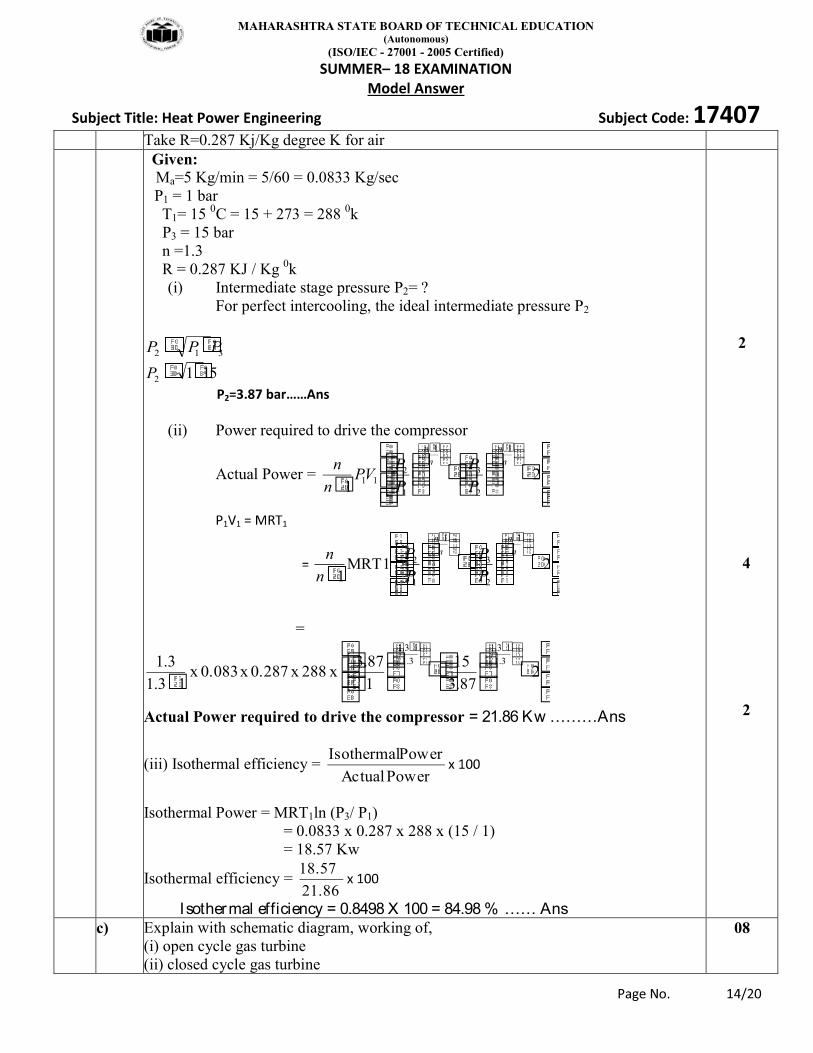
5 b) A two stage, single acting reciprocating air compressor takes in air at the rate of 5kg per minute. Intake pressure and temperature are 1bar and 15 degree Celsius. The air is compressed to a final pressure of 15bar. The intermediate pressure is ideal and intercooling is perfect.Take n = 1.3. Neglect the clearance and determine (i) Intermediate stage pressure (ii) Power required to drive the compressor (iii) Isothermal efficiency
8
MAHARASHTRA STATE BOARD OF TECHNICAL EDUCATION (Autonomous)
(ISO/IEC - 27001 - 2005 Certified)
Take R=0.287 Kj/Kg degree K for air Given:
Ma=5 Kg/min = 5/60 = 0.0833 Kg/sec P1 = 1 bar T1= 15 0C = 15 + 273 = 288 0k P3 = 15 bar n =1.3 R = 0.287 KJ / Kg 0k
(i) Intermediate stage pressure P2= ? For perfect intercooling, the ideal intermediate pressure P2
312 PPP
1512P
(ii) Power required to drive the compressor
Actual Power = 21
1
2
3
1
1
211
n
n
n
n
P
P
P
PVP
n
n
2MRT11
1
2
3
1
1
2n
n
n
n
P
P
P
P
n
n
=
287.3
15
1
87.3 x 288 x 0.287 x 0.083 x
13.1
3.1 3.1
13.1
3.1
13.1
Actual Power required to drive the compressor = 21.86 Kw ………Ans
(iii) Isothermal efficiency = Power Actual
Power Isothermal
Isothermal Power = MRT1ln (P3/ P1) = 0.0833 x 0.287 x 288 x (15 / 1) = 18.57 Kw
Isothermal efficiency = 21.86
18.57
Isothermal efficiency = 0.8498 X 100 = 84.98 % …… Ans
2
4 2
c) Explain with schematic diagram, working of, (i) open cycle gas turbine (ii) closed cycle gas turbine
08
MAHARASHTRA STATE BOARD OF TECHNICAL EDUCATION (Autonomous)
(ISO/IEC - 27001 - 2005 Certified)
(i) Open Cycle Gas Turbine
Fig. Open Cycle Gas Turbine
Working: Fig. shows open cycle gas turbine which consists of compressor, combustion chamber, turbine, generator. The compressor and turbine are mounted on same shaft. Combustion chamber is placed in between compressor and turbine for combustion of fuel. Generator is coupled with turbine shaft for generation of power. Fresh air enters the compressor at ambient temperature at point 1 and it is compressed to point 2 where its pressure and temperature are increased. The high pressure air enters the combustion chamber where the fuel is burned at constant pressure. Heat is added by directing burning the fuel into combustion chamber at constant pressure during process 2 to 3. The high temperature (and pressure) gas enters the turbine where it expands during process 3 to 4 to ambient pressure and produces work. Finally exhausted to atmosphere.
(ii) Closed cycle gas turbine:
02
02
02
02
MAHARASHTRA STATE BOARD OF TECHNICAL EDUCATION (Autonomous)
(ISO/IEC - 27001 - 2005 Certified)
Fig. Closed cycle gas turbine
In above figure shows a closed cycle gas turbine which consists of compressor, heating chamber gas turbine which drives the generator, compressor and a cooling chamber. In this turbine air is compressed isentropically and then passed into heating chamber. Thecompressed air is heated with the help of some external source and made to flow over turbine blades. The gas while flowing over the blades gets expand from the turbine gas is passed to cooling chamber where it is cooled at constant pressure with the help ofcirculating air is circulated through compressor.
6 Attempt any FOUR of the folloeing 16 a) Calculate the air standard efficiency of engine working on Otto cycle. The bore and
stroke of the cylinder are 17 cm and 30 cm respectively. The clearance volume is 0.002 m3
04
Solution. Given d = diameter of cylinder =bore= 17 cm= 0.17m L = stroke length= 30 cm = 0.30 m Clearance volume = Vc=V2 = 0.002 m3
VS
2. l 2 x 0.3 m3
= 6.81 x 10⁻³ m3
V1 = V c + Vs = 0.002 + 6.81 x 10-3 = 0.00881 m3
01
MAHARASHTRA STATE BOARD OF TECHNICAL EDUCATION (Autonomous)
(ISO/IEC - 27001 - 2005 Certified)
Compression ratio (r) = (V1/V2) =(0.00881/0.002) = 4.405 cycle = (1 1 / r -1) X 100
=(1 1 / (4.405)1.4 -1) X 100 = 44.73 %.
01
02
01 b) Steam enters in engine at a pressure of 12bar with a 670C of superheat. It is exhausted at a pressure of 0.15bar and 0.95 dry. Find drop in enthalpy of the steam.
04
Answer: From Steam Table:
01
01
02
c) Explain construction and working of Rock drill using compressed air. 04
Fig. Rock Drill
Construction: It consist of air tube system, valves pile driver , handle and
01
MAHARASHTRA STATE BOARD OF TECHNICAL EDUCATION (Autonomous)
(ISO/IEC - 27001 - 2005 Certified)
drill bit. Inside the pneumatic drill is a series of air tubes that connect to the pile driver, and then to the drill bit at the bottom. Working : The compressed air, delivered from the diesel-powered compressor,enters the drill and moves through the air tube circuit system. The movement of the air pushes the pile driver down onto the drill bit, causing the drill bit to pound into the surface of the road, sidewalk or pavement being drilled. The downward movement of the drill, in combination with the vibration of the drill pounding into the surface, causes a valve inside the air tubing to invert. This valve's inversion causes the air to circulate in the opposite direction; the new flow of air causes the drill to bounce back away from the earth. The valve then flips again, and the air flow, combined with the power of gravity, forces and pulls the drill bit back to the surface. All of this happens very rapidly. The drill bit smashes into the surface at an average of 25 times per second, 1500 times a minute. You can easilysee how this would be more effective than a man (or woman) swinging a sledge hammer only 5 or 10 times in a minute.
01
02
d) Explain working principle of Turboprop engine, with a neat sketch . 04 (Sketc-02marks, working principle-02marks)
Construction and working: It consist of diffuser, compressor, combustion chamber, turbine, nozzle and propeller. Figure shows a turboprop system employed in aircrafts. Here the expansion of gases takes place partly in turbine 80% and partly 20% in the nozzle. The power developed by the turbine is consumed in running the compressor and the propeller. The propeller and jet produced by the nozzle give forward motion to the aircraft. The overall
02
02
MAHARASHTRA STATE BOARD OF TECHNICAL EDUCATION (Autonomous)
(ISO/IEC - 27001 - 2005 Certified)
efficiency of the turbo prop is improved by providing the diffuser before the compressor as shown. The pressure rise takes place in the diffuser. This pressure rise take due to conversion of kinetic energy of the incoming air (equal to aircraft velocity) into pressure energy by diffuser.
e) Compare: Ultimate analysis and proximate analysis. 04 (any two point-04 marks)
Sr. No.
Ultimate Analysis Proximate Analysis
1 Ultimate analysis of coal is complete breakdown of coal into chemical constituents.
Proximate analysis of coal is complete breakdown of coal into physical constituents.
2 This analysis gives percentage of carbon , hydrogen, oxygen, sulpher and ash.
This analysis gives percentage of moisture , volatile matter, fixed carbon and ash.
04
f) Explain the working principle of tidal power plant with neat sketch. 04 Ans: (sketch-1mark each, working-02 marks)
Working of Tidal power plant: During high tide the water flow from sea into the tidal basin through water turbine as the level of water in sea is more than tidal basin. This operates the turbine and generator and power is produced. Potential energy of sea water converted into mechanical energy by turbine and it converts into electrical by generators. During low tide water flow from tidal basin into sea as water level in the sea is lower than basin level in both cases generation of power is same. Only difference in that rotation of turbine blade is opposite.