Page 1
MAHARASHTRA STATE BOARD OF TECHNICAL EDUCATION (Autonomous)
(ISO/IEC - 27001 - 2005 Certified)
Model Answer: Winter 2017 Subject: Design of RCC Structures
---------------------------------------------------------------------------------------------------------------
Page No. 1 / 27
Sub. Code: 17604
Important Instructions to examiners:
1) The answers should be examined by key words and not as word-to-word as given in the model answer
scheme.
2) The model answer and the answer written by candidate may vary but the examiner may try to assess the
understanding level of the candidate.
3) The language errors such as grammatical, spelling errors should not be given more importance. (Not
applicable for subject English and Communication Skills.)
4) While assessing figures, examiner may give credit for principal components indicated in the figure. The
figures drawn by the candidate and those in the model answer may vary. The examiner may give credit
for any equivalent figure drawn.
5) Credits may be given step wise for numerical problems. In some cases, the assumed constant values may
vary and there may be some difference in the candidate’s answers and the model answer.
6) In case of some questions credit may be given by judgment on part of examiner of relevant answer based
on candidate’s understanding.
7) For programming language papers, credit may be given to any other program based on
equivalent concept.
---------------------------------------------------------------------------------------------------------------------------------
Que.
No.
Sub.
Que. Model Answers Marks
Total
Marks
Q.1 (A)
(a)
(b)
Ans.
Attempt any THREE of the following:
Define ‘Characteristic load’ and ‘characteristic strength’ of
material.
i) Characteristic load
Characteristic load is that value of load which has 95% probability
of not being exceeded during the service life time of the structure.
ii) characteristic strength
Characteristic strength of a material is the value of the material
below which not more than 5% of test results are expected to fail.
Why over reinforced section are not provided in LSM?
1) In over-reinforced section, percentage of steel is more than critical
percentage.
2) Due to this, the concrete crushes reaching its ultimate strain before
steel reaching its yield point.
3) In this case, the beam will fail initially due to overstress in the
concrete, suddenly without giving any warning.
4) Therefore, design codes restrict the percentage of steel in RC
sections to that of balanced section thus disallowing over- reinforced
section.
2
2
1
each
(12)
4
4
Page 2
MAHARASHTRA STATE BOARD OF TECHNICAL EDUCATION (Autonomous)
(ISO/IEC - 27001 - 2005 Certified)
Model Answer: Winter 2017 Subject: Design of RCC Structures
---------------------------------------------------------------------------------------------------------------
Page No. 2 / 27
Sub. Code: 17604
Que.
No.
Sub.
Que. Model Answers Marks
Total
Marks
1. (c)
Ans.
(d)
Ans.
State any two ductile detailing provision as per IS : 13920
Requirement for longitudinal reinforcement in flexural members:
1) The top as well as bottom reinforcement shall consist of at
least two bars throughout the member length
2) The maximum steel ratio on any face at any section, shall
not exceed Pmax = 0.025
3) The positive steel at a joint face must be at least equal to
half the negative steel at that face.
(NOTE : Any other members ductile detailing provisions should be
considered)
State two advantages and two disadvantages of prestressed
concrete.
Advantages of prestressed concrete.
1. The use of high strength concrete and steel in prestressed
members results in lighter and slender members which is not
possible in RC members.
2. In fully prestressed members the member is free from tensile
stresses under working loads, thus whole of the section is
effective.
3. In prestressed members, dead loads may be counter-balanced
by eccentric prestressing.
4. Prestressed concrete member possess better resistance to shear
forces due to effect of compressive stresses presence or
eccentric cable profile.
5. Use of high strength concrete and freedom from cracks,
contribute to improve durability under aggressive
environmental conditions.
6. Long span structures are possible so that saving in weight is
significant & thus it will be economic.
2
each
(any
two)
1 each
(any
two)
4
Page 3
MAHARASHTRA STATE BOARD OF TECHNICAL EDUCATION (Autonomous)
(ISO/IEC - 27001 - 2005 Certified)
Model Answer: Winter 2017 Subject: Design of RCC Structures
---------------------------------------------------------------------------------------------------------------
Page No. 3 / 27
Sub. Code: 17604
Que.
No.
Sub.
Que. Model Answers Marks
Total
Marks
1. (d)
(e)
Ans.
7. Factory products are possible.
8. Prestressed members are tested before use.
9. Prestressed concrete structure deflects appreciably before
ultimate failure, thus giving ample warning before collapse.
10. Fatigue strength is better due to small variations in prestressing
steel, recommended to dynamically loaded structures.
Disadvantages of Prestressed Concrete
1. The availability of experienced builders is scanty.
2. Initial equipment cost is very high.
3. Availability of experienced engineers is scanty.
4. Prestressed sections are brittle.
5. Prestressed concrete sections are less fire resistant.
When minimum shear reinforcement is provided? State the
equation use for minimum shear reinforcement giving meaning of
terms used in it.
If Nominal shear stress (ζv) < Design shear strength of concrete (ζc),
minimum shear reinforcement in form of stirrup shall be provided
such that,
Asv 0.4/ 0.87fy
(b x Sv)
Where,
Asv = total cross section area of stirrups legs effective in shear
Sv = stirrups spacing along the length of the member
b = breadth of beam or web of flanged beam
fy= characteristic strength of stirrup reinforcement in N/mm2 which
shall not be taken greater than 415N/ mm2.
1 each
(any
two)
2
2
4
4
Page 4
MAHARASHTRA STATE BOARD OF TECHNICAL EDUCATION (Autonomous)
(ISO/IEC - 27001 - 2005 Certified)
Model Answer: Winter 2017 Subject: Design of RCC Structures
---------------------------------------------------------------------------------------------------------------
Page No. 4 / 27
Sub. Code: 17604
Que.
No.
Sub.
Que. Model Answers Marks
Total
Marks
Q.1. (B)
(a)
Ans.
(b)
Ans.
Attempt any ONE:
A rectangular beam 230 mm wide and 400mm effective depth is
reinforced with 4 bars of 16 mm diameter on tension side.
Calculate the ultimate moment of resistance if M20 grade
concrete and Fe415 steel is used.
2 2
max
max
u
u
4 (16) 804.25 4
0.87 0.87 415 804.25
0.36 0.36 20 230
175.35
0.48 0.48 400 192
175.35 < 192
, section is under reinforced,
M 0.87 . .( 0.42 )
M
st
y st
u
ck
u
u
u u
y st u
A mm
f AX
f b
X mm
X d mm
X mm X mm
Hence
f A d X
6
u
u
0.87 415 804.25 400 (0.42) (175.35)
M 94.764 10
M 94.764
N mm
kN m
Draw stress-strain diagram for singly reinforced beam in LSM.
State the position of neutral axis in terms of ‘d’ for critical section
and maximum moment of resistance in terms of b and d using
assumption in LSM as per IS 456-2000.
1
1
1
1
1
1
3
(6)
6
Page 5
MAHARASHTRA STATE BOARD OF TECHNICAL EDUCATION (Autonomous)
(ISO/IEC - 27001 - 2005 Certified)
Model Answer: Winter 2017 Subject: Design of RCC Structures
---------------------------------------------------------------------------------------------------------------
Page No. 5 / 27
Sub. Code: 17604
Que.
No.
Sub.
Que. Model Answers Marks
Total
Marks
1
2
(b)
(a)
Ans.
As per IS:456-2000, values of neutral axis in terms of ‘d’ for critical
section and max. Moment of resistance in terms of b & d are given in
table.
Steel type fy (N/mm2)
Xu lim
uMlim
Mild steel 250 0.53 d 0.149 fck bd2
Fe 415 415 0.48 d 0.138 fck bd2
Fe 500 500 0.46 d 0.133 fck bd2
Attempt any TWO:
A Design a slab for hall 4 m x 10 m for residential building with
following data :
Live load = 22 kN/m , Floor finish = 21 kN/m
Width of support =230 mm , M.F = 1.4
Main Steel 10 mm diameter bars of Fe415
Distribution steel 6 mm diameter bars of Fe250
Use M20 grade concrete. Also draw the reinforcement details
(No Checks)
2 2
2 2
ck y
Given:
=4m LL=2 kN/m FF = 1 kN/m
MF =1.4 f =20N/mm , f =415N/mm
Step (1)
Span 4000d= = =142.857 mm
20×MF 20×1.4
Assuming, 10mm bars and cover of 20 mm
10D = d+c+ =142.857+20+ =167.857 mm
2 2
Provide,
l
D =170 mm
10 d = 1700 - 20 - = 145 mm
2
Step (2)
Effective span
Min. of (a) & (b)
a) + d = 4000 + 145 = 4145 mm = 4.145m
b) + t =4000 + 230 = 4230 mm = 4.230m
4.145
e
e
e
l l
l l
l m
3
1
1
6
(16)
Page 6
MAHARASHTRA STATE BOARD OF TECHNICAL EDUCATION (Autonomous)
(ISO/IEC - 27001 - 2005 Certified)
Model Answer: Winter 2017 Subject: Design of RCC Structures
---------------------------------------------------------------------------------------------------------------
Page No. 6 / 27
Sub. Code: 17604
Que.
No.
Sub.
Que. Model Answers Marks
Total
Marks
2. (a)
d
Step (3)
Load & B M calculation
i) D.L. of slab = 0.170×1×1×25 = 4.25 kN/m
ii) L.L. of slab = 2×1×1= 2.0 kN/m
i) F.F. of slab = 1×1×1 = 1.0 kN/m
Total load = 7.25 kN/m
Factored load (w )=1.5×w
2 2d e
max u
2 6
ck reqd
2 6
reqd
reqd
=1.5×7.25
= 10.875 kN/m
w l 10.875×(4.145)BM = M = =
8 8
BM = Mu=23.355kN-m
Step (4)
Check for depth
Mu =M
0.138f b d =23.355×10
0.138×20×1000× d =23.355×10
d =91.988mm<
u
d=145mm ........Ok
6
ckst 2
y ck
6
st 2
2
st
2
x
st
Step (5)
Main steel and its spacing
0.5f 4.6×M ×10A = 1- 1- bd
f f bd
0.5×20 4.6×23.355×10A = 1- 1- ×1000×145
415 20×1000×(145)
A =479.196mm
Spacing of bar Min. of
π1000× 10
1000×A 4a) S = =A
u
x
x
x
=163.899mm479.196
b) S =3d=3×145=435mm
c) S =300mm
S =160mm c/c
Provide 10 mm bars @ 160mm c/c along the shorter span
1
1
1
1
Page 7
MAHARASHTRA STATE BOARD OF TECHNICAL EDUCATION (Autonomous)
(ISO/IEC - 27001 - 2005 Certified)
Model Answer: Winter 2017 Subject: Design of RCC Structures
---------------------------------------------------------------------------------------------------------------
Page No. 7 / 27
Sub. Code: 17604
Que.
No.
Sub.
Que. Model Answers Marks
Total
Marks
2 (a)
(b)
Ans.
2
std
2
dy
d
y
Step 6)
Distribution steel and its spacing
0.15 0.15A = bD= ×1000×170=255mm
100 100
Providing, 6mm bars,
Spacing of bars is equal to min. of
π1000× 6
1000×A 4a) S = = = 110.823mmAst 255
b) S =5d=5×145=725mm
c)
y
y
S =450mm
S =110.823mm c/c
Provide 6 mm bars @ 110 mm c/c along the longer span
Design a two way slab with following details:
Size of room = 3.00 m X 4.50 m, LL = 22 kN/m
FF = 21 kN/m , Width of support =230 mm
BM coefficient αx = 0.104, αy = 0.046
Also draw the reinforcement details using 10 mm diameter bars of
Fe 415. Use M20 grade concrete.
2
ck
2 2
2
y
Given: =3m, =4.5m , f =20N/mm ,
LL=2 kN/m , FF = 1 kN/m
f = 415N/mm
0.104 0.046
x
x y
l ly
1
1
8
Page 8
MAHARASHTRA STATE BOARD OF TECHNICAL EDUCATION (Autonomous)
(ISO/IEC - 27001 - 2005 Certified)
Model Answer: Winter 2017 Subject: Design of RCC Structures
---------------------------------------------------------------------------------------------------------------
Page No. 8 / 27
Sub. Code: 17604
Que.
No.
Sub.
Que. Model Answers Marks
Total
Marks
2 (b)
2 2
Step (1)
Slab thickness,
as =3m <3.5m and LL = 2kN/m <3kN/m 415 .
3000D = = =107.142 mm
28 28
Provide, D = 110 mm
Assuming, cover of 15 mmand roviding10mm bars
10d = D- c - = 110- 15 - =90mm
2 2
x
x
l and Fe isused
l
p
Provide, D = 110 mm d = 90 mm
Step (2)
Effective span
= +d = 3000 +90 =3090 mm =3.09 m
= +d = 4500+90 = 4590 mm = 4.59
Step (3) Load & B M calculation
i) D.L. of slab = 0.110 × 1 × 1 × 25 = 2.75kN/m
ii) L.L. of slab = 2×1×1=
x xe x
y ye y
l l l
l l l
d
2
x d
2.0kN/m
i) F.F. of slab = 1×1×1 = 1.0 kN/m
Total load =5.75 kN/m
Factored load ( )=1.5×
=1.5×5.75
= 8.625 kN/m
BM calculations,
M = . . =(0.104 8.625 (x xe
w w
u w l
2
x
2 2
y d
x
3.09) )
Mu = 8.565kN-m
M = . . =(0.046 8.625 (3.09) )
Mu =3.788kN-m
y xeu w l
max ux
2 6
ck reqd
reqd
Step (4)
Check for depth
Mu =M
0.138f b d = 8.565×10
d =55.71mm < d=90mm ........Ok
1
1
1
1
1
Page 9
MAHARASHTRA STATE BOARD OF TECHNICAL EDUCATION (Autonomous)
(ISO/IEC - 27001 - 2005 Certified)
Model Answer: Winter 2017 Subject: Design of RCC Structures
---------------------------------------------------------------------------------------------------------------
Page No. 9 / 27
Sub. Code: 17604
Que.
No.
Sub.
Que. Model Answers Marks
Total
Marks
2 (b)
6
ckstx 2
y ck
6
st 2
2
st
Step (5)
Main steel and its spacing
In X direction
0.5f 4.6×M ×10A = 1- 1- bd
f f bd
0.5×20 4.6×8.565×10A = 1- 1- ×1000×90
415 20×1000×(90)
A = 282.056 mm
ux
2
x
st
x
x
x
'
cksty
y
Spacing of bar Min. of
π1000× 10
1000×A 4a) S = = = 278.454mmA 282.056
b) S = 3d = 3×90 = 270mm
c) S = 300mm
S = 270mm c/c
Provide 10 mm bars @ 270 mm c/c
In Y direction
d 90 10 80
0.5fA = 1- 1-
f
d mm
6
2
ck
6
sty 2
2
sty
2
min
2 2
sty min
y
sty
4.6×M ×10bd'
f bd'
0.5×20 4.6×3.788×10A = 1- 1- ×1000×80
415 20×1000×(80)
A = 136mm
0.121000 110 132
100
A =136 > (132 )
Spacing of bar Min. of
1001000×A
a) S = =A
st
st
uy
A mm
mm A mm
2
y
y
y
π0× 10
4 = 577.498mm136
b) S = 3d = 3×80 = 240mm
c) S = 300mm
S = 240mm c/c
Provide 10 mm bars @ 240 mm c/c
1
1
Page 10
MAHARASHTRA STATE BOARD OF TECHNICAL EDUCATION (Autonomous)
(ISO/IEC - 27001 - 2005 Certified)
Model Answer: Winter 2017 Subject: Design of RCC Structures
---------------------------------------------------------------------------------------------------------------
Page No. 10 / 27
Sub. Code: 17604
Que.
No.
Sub.
Que. Model Answers Marks
Total
Marks
2 (b)
(c)
Ans.
Design a cantilever chajja with following data:
Span = 1.2 m, L.L. = 2 kN/m2. Floor finish = 1 kN/m
2, Width of
support = 230 x 400 mm beam. Draw the reinforcement details.
Use 10 mm diameter bars Fe 415 and 6 mm diameter bars of
Fe 250. Use M 20 grade concrete.
2 2
2 2
ck y
:
Span= =1.2m =1200mm,
LL=2 kN/m , FF=1 kN/m
Support = 230 400 mm
f 20N/mm , f 415N/mm
1)
7 . .
, M.F.1.4, cover=15 mm and 10
1200122.45
7 1.4
1222
Given
l
Step
Slab thickness
Spand
M F
Assume mm
d mm
D d c
10
.45 15 142.452
, D=150mm,
10d=150-15- =130mm
2
D=150mm, d=130mm
Step (2)
Effective span
1301200 1265 1.265
2 2e
mm
provide
dl l mm m
1
1
1
8
Page 11
MAHARASHTRA STATE BOARD OF TECHNICAL EDUCATION (Autonomous)
(ISO/IEC - 27001 - 2005 Certified)
Model Answer: Winter 2017 Subject: Design of RCC Structures
---------------------------------------------------------------------------------------------------------------
Page No. 11 / 27
Sub. Code: 17604
Que.
No.
Sub.
Que. Model Answers Marks
Total
Marks
2 (b)
d
3)
Load cal. and BM
i) D.L. of slab =0.150 1 1 25 3.75 /
ii) L.L. of slab =2 1 1 2 /
iii) F.F. of slab =1 1 1 1 /
laod (w) = 6.75kN / m
Factored load w 1.5 6.75 10.125 /
Step
kN m
kN m
kN m
Total
kN m
2 2
max ux
2 6
ck reqd
2 6
reqd
reqd
10.125 1.2658.101
2 2
4)
for depth ,
Mu = M
0.138f b d = 8.101×10
0.138 20 1000 d 8.101 10
d = 54.176 mm < d=130mm ........Ok
e
u
wd lBM M kN m
Step
Check
6
ckst 2
y ck
6
st 2
2
st
2
stmin
2
st
Step (5)
Main steel and its spacing
0.5f 4.6×M ×10A = 1- 1- bd
f f bd
0.5×20 4.6×8.101 10A = 1- 1- ×1000×130
415 20×1000×(130)
A = 177.722 mm
0.12A = 1000 130 156
100
A = 177.722 mm
u
mm
2
stmin
2
x
st
x
x
x
> A (156 )
Spacing of bar Min. of
π1000× 10
1000×A 4a) S = = = 441.925mmA 177.722
b) S = 3d = 3×130 = 390mm
c) S = 300mm
S = 300mm c/c
Provide 10 mm bars @ 300 mm c/c
mm
1
1
1
1
Page 12
MAHARASHTRA STATE BOARD OF TECHNICAL EDUCATION (Autonomous)
(ISO/IEC - 27001 - 2005 Certified)
Model Answer: Winter 2017 Subject: Design of RCC Structures
---------------------------------------------------------------------------------------------------------------
Page No. 12 / 27
Sub. Code: 17604
Que.
No.
Sub.
Que. Model Answers Marks
Total
Marks
2
Q.3
(c)
(a)
Ans.
2
st sty min
2
y
st
y
y
y
6)
0.15A =A = 1000 150 225
100
Assuming, 6 mm bars
Spacing of bar Min. of
π1000× 6
1000×A 4a) S = = = 125.66mmA 225
b) S = 5d = 5×130 = 650mm
c) S = 450mm
S = 120mm c/c
Provide 6 mm bars @ 120
Step
mm
mm c/c
Attempt any FOUR:
Find the moment of resistance of ‘T’ beam with following data:
Df =120 mm, bf = 1200 mm, bw = 300 mm, d = 450 mm, Area of
tension reinforcement = 2000 mm2. Use M20 grade concrete and
Fe 415 steel.
u
f u
u
u f
Step 1
Find x
0.36 fck b x = 0.87 fy Ast
0.36 20 1200 x = 0.87 415 2000
x = 83.57mm < D =120mm
1
1
1
8
(16)
Page 13
MAHARASHTRA STATE BOARD OF TECHNICAL EDUCATION (Autonomous)
(ISO/IEC - 27001 - 2005 Certified)
Model Answer: Winter 2017 Subject: Design of RCC Structures
---------------------------------------------------------------------------------------------------------------
Page No. 13 / 27
Sub. Code: 17604
Que.
No.
Sub.
Que. Model Answers Marks
Total
Marks
3 (a)
(b)
Ans.
umax
umax
Step 2
Find x
x = 0.479d for Fe415
= 0.479 450
= 215.55mm
As
u umax
u
u u u
u
x < x section is under reinforced
Step 3
Find M
M =T Z
= 0.87 fy Ast d-0.42x
6
=0.87 415 2000 450 0.42 83.57
=299.59 10 N-mm
Mu =299.59 kN-mm
A ‘T’ beam and ‘L’ beam are provided over a hall of 10m X 8m.
Spacing of beam is 2.5 m c/c and span 8 m. Calculate the effective
flange width of ‘T’ and ‘L’ beam. Width of rib = 230 mm, flange
thickness = 120 mm.
Note : Answer may vary depending upon assumption of any one
condition that is support thickness / width assumed or not,
accordingly give appropriate marks.
Case : When width of support is assumed.
o
Step 1
Assuming effective span for the beam = c/c distance betwwen the supports
and taking width of support = 230 mm
230 230 l = 8000
2 2
= 8230 mm
0
Step 2
Effective flange width of 'T'beam
l bf = 6 or c/c distance between supports --- whichever is small
6
8230 = 230 6 120 or 2
6
w fb D
f
500 mm ---- whichever is small
= 2321.66 mm or 2500 mm ---- whichever is small
b = 2321.66 mm
1
1
1
1
1½
4
Page 14
MAHARASHTRA STATE BOARD OF TECHNICAL EDUCATION (Autonomous)
(ISO/IEC - 27001 - 2005 Certified)
Model Answer: Winter 2017 Subject: Design of RCC Structures
---------------------------------------------------------------------------------------------------------------
Page No. 14 / 27
Sub. Code: 17604
Que.
No.
Sub.
Que. Model Answers Marks
Total
Marks
3 (b)
(c)
Ans.
0f
Step 3
Effective flange width of 'L' beam
l b = 3 or 2500 mm --- whichever is small
12
8230 = 230 3 120 or 2500 mm --- whichever is small
12
w fb D
f
= 1275.83 mm 2500 mm --- whichever is small
b = 1275.83 mm
OR
Case : When width of support is not assumed.
o
Step 1
Assuming effective span for the beam = Shorter dimension of hall
l = 8000
Step 2
Effective flange width of 'T'beam
bf = 0l 6 or c/c distance between supports --- whichever is small6
8000 = 230 6 120 or 2500 mm ---- whichever is small
6
= 2283.33 mm or 2500 mm ---- whichever i
w fb D
f
s small
b = 2283.33 mm
0f
Step 3
Effective flange width of 'L' beam
l b = 3 or 2500 mm --- whichever is small
12
8000 = 230 3 120 or 2500 mm --- whichever is small
12
w fb D
f
= 1256.66 mm 2500 mm --- whichever is small
b = 1256.66 mm
Define ‘Development length’. Also determine the development
length for 16 mm diameter bar of Fe 415 in tension .Take τbd =1.4
N/mm2 for a plain bar in tension.
Development length: It is the length required to develop the stress in
the bar from zero to maximum by transfer of stress from concrete to
steel.
1½
1
1½
1½
2
4
4
Page 15
MAHARASHTRA STATE BOARD OF TECHNICAL EDUCATION (Autonomous)
(ISO/IEC - 27001 - 2005 Certified)
Model Answer: Winter 2017 Subject: Design of RCC Structures
---------------------------------------------------------------------------------------------------------------
Page No. 15 / 27
Sub. Code: 17604
Que.
No.
Sub.
Que. Model Answers Marks
Total
Marks
3 (c)
(d)
Ans.
(e)
Ans.
2 2
d
Given data: = 16mm, fy=415 N/mm , 1.4N/mm ,bar is in tension
0.87 L
4 '
' 1.6 ---- for deformed bar 0.87 415 16
= the value of 4 1.6 1.4
bd
bd
bd bd
b
fy
increased by 60%
= 644.73mm
d
Calculate the shear resisted by two bent up bars of Fe 415.
Take α = 450.
Note : Answer may vary depending upon assumption of bar
diameter, accordingly give appropriate marks.
2 0
Assume, bar diameter = 20 mm
Shear resisted by 2-bentup bars = Vusb
Vusb = 0.87 sin
= 0.87 415 2 20 sin 454
= 160410 N
= 160.41 KN
fy Asb
Write any four assumptions in limit sate of collapse in
compression as per IS 456- 2000.
i) Plane section normal to the axis remains plane after bending.
ii) The maximum strain in concrete at the outermost compression fiber
is taken as 0.0035 in bending.
iii) For design purpose, the compressive strength of concrete in
structure shall be assumed to be 0.67 times the characteristic strength.
The partial safty factor ϒm= 1.5 shall be applied in addition to this.
iv) The tensile strength of concrete is ignored.
v) The design stress in steel reinforcement is obtained from the strain
at reinforcement level using idealized stress-strain curve for the types
of reinforcement used.
vi) For design purposes the partial safety factor ϒm equal to 1.15 shall
be applied.
vii) The maximum compressive strain in concrete in axial
compression is taken as 0.002.
viii) The maximum compressive strain at the highly compressed
extreme fiber in concrete subjected to axial compression and bending
and when there is no tension on the section shall be 0.0035 minus 0.75
times the strain at the least compressed extreme fiber.
1
1
2
2
1 each
(any
four)
4
4
4
Page 16
MAHARASHTRA STATE BOARD OF TECHNICAL EDUCATION (Autonomous)
(ISO/IEC - 27001 - 2005 Certified)
Model Answer: Winter 2017 Subject: Design of RCC Structures
---------------------------------------------------------------------------------------------------------------
Page No. 16 / 27
Sub. Code: 17604
Que.
No.
Sub.
Que. Model Answers Marks
Total
Marks
Q.4 (A)
(a)
Ans.
Attempt any THREE:
State methods of prestressing and explain one of them in brief.
i) Pre-Tensioning
1. Hoyer system
ii) Post-Tensioning
1. Freyssinet system
2. Magnel system
3. Leonhardt system
4. Lee-McCall system
5. Gifford-Udall system
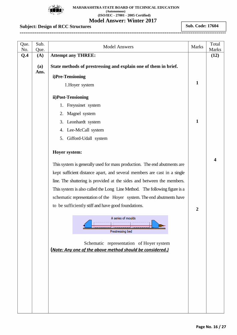
Hoyer system:
This system is generally used for mass production. The end abutments are
kept sufficient distance apart, and several members are cast in a single
line. The shuttering is provided at the sides and between the members.
This system is also called the Long Line Method. The following figure is a
schematic representation of the Hoyer system. The end abutments have
to be sufficiently stiff and have good foundations.
Schematic representation of Hoyer system
(Note: Any one of the above method should be considered.)
1
1
2
(12)
4
Page 17
MAHARASHTRA STATE BOARD OF TECHNICAL EDUCATION (Autonomous)
(ISO/IEC - 27001 - 2005 Certified)
Model Answer: Winter 2017 Subject: Design of RCC Structures
---------------------------------------------------------------------------------------------------------------
Page No. 17 / 27
Sub. Code: 17604
Que.
No.
Sub.
Que. Model Answers Marks
Total
Marks
4 (b)
Ans.
(c)
Ans.
(d)
Ans.
Calculate the load carrying capacity of a column 400 mm X 400
mm is reinforced with 1% steel of Fe415. Use M20 grade concrete.
g
2
sc
Step 1
Gross area, A = 400 400
= 160000mm
Step 2
Area of steel A = 1% of Ag
= 0.001 160000
2
C sc
2
= 1600 mm
Step 3
Area of concrete A Ag - A
= 160000 - 1600
= 158400 mm
4
Ultimate load carrying
Step
u
u sc
capacity (P )
P = 0.4 + 0.67 A
= 0.4 20 158400 + 0.67 415 1600
= 1712080N
Cfck A fy
= 1712.08 kN
State the critical combination of loads as per IS 456-2000. Also
state the partial safety factors for concrete and steel for collapse.
IS 456-2000 recommends the following critical load combination of
loads –
i) Dead load + Live / Imposed load (DL + LL)
ii) Dead load + Wind load (DL + WL)
iii) Dead load + Live / Imposed load + Wind load (DL + LL + LL)
Partial safety factors for concrete and steel for collapse are -
For concrete ----- ϒmc = 1.5
For Steel ----- ϒms =1.15
Define ‘doubly reinforced section’. State any two condition in
which doubly reinforced section is provided.
Doubly Reinforced Section: The R.C.C beam in which the
reinforcement is provided on both tension and compression side is
known as doubly reinforced beam.
1
1
1
1
2
1
1
2
4
4
Page 18
MAHARASHTRA STATE BOARD OF TECHNICAL EDUCATION (Autonomous)
(ISO/IEC - 27001 - 2005 Certified)
Model Answer: Winter 2017 Subject: Design of RCC Structures
---------------------------------------------------------------------------------------------------------------
Page No. 18 / 27
Sub. Code: 17604
Que.
No.
Sub.
Que. Model Answers Marks
Total
Marks
4 (d)
(B)
(a)
Ans.
Conditions where doubly reinforced section is provided are :-
i) When the applied moment exceeds the moment resisting capacity
of a singly reinforced beam.
ii) When the dimension b and d of the section are restricted due to
architectural, structural or constructional purposes.
iii) When the sections are subjected to reversal of bending moment.
e.g. piles, underground water tank etc.
iv) In continuous T-beam where the portion of beam over middle
support has to be designed as doubly reinforced.
v) When the beams are subjected to eccentric loading, shocks or
impact loads.
Attempt any ONE:
Determine the ultimate moment of resistance of a doubly
reinforced section 250 mm X 400 mm (effective), if Ast = 1500
mm2, Asc = 600 mm
2. Assume M20 grade concrete and Fe 415
steel. fsc = 353 N/mm2, d’/ d = 0.1, fcc = 0.45 fck.
umax
umax
u
2
Step 1 :Find X 0.479 ------ for Fe415
=0.479 400
X =191.6 mm
Step 2 : Find actual X
fcc= 0.45fck = 0.45x 20=9 N/mm
d
u
umax
u
(0.36 . . ) ( ( )) (0.87 )
(0.36 20 250) (600(353 9)) (0.87 9 1500)
1800 206400 541575
X 186.20
, < X inf sec
Step 2 : Find Moment of Resistance M
0.u
fck Xu b Asc fsc fcc fyAst
Xu
Xu
mm
As Xu Beamisunder re orced tion
M
6
36 0.42 '
0.36 20 250 186.20 400 (0.42 186.20) 353 9 600 400 40
182.15 10
182.15
ck u u sc cc sc
u
u
u
f b X d X f f A d d
M
M N mm
M kN m
OR
umax
umax
Step 1 :Find X 0.479 ------ for Fe415
=0.479 400
X =191.6 mm
d
1 each
(any
two)
1
1
1
1
1
1
1
4
(6)
6
Page 19
MAHARASHTRA STATE BOARD OF TECHNICAL EDUCATION (Autonomous)
(ISO/IEC - 27001 - 2005 Certified)
Model Answer: Winter 2017 Subject: Design of RCC Structures
---------------------------------------------------------------------------------------------------------------
Page No. 19 / 27
Sub. Code: 17604
Que.
No.
Sub.
Que. Model Answers Marks
Total
Marks
4 (a)
(b)
Ans.
2
2
2
1
2
1 2
u1
Step 2 : Find actual Ast
( ) (353 9) 600 Ast 571.665
0.87 0.87 415
Step 3 : Find actual Ast
Ast 1500 571.665 928.335
Step 4 : Find actual X
fsc fcc Ascmm
fy
Ast Ast mm
1u1
u umax 1
u
0.87 0.87 415 928.335 X 186.20
0.36 0.36 20 250
X X
Beam is under reinforced section.
Step 5 : Find Moment of Resistance M
fcc= 0.45fck = 0.45x 20=9 N/mm
fy Astmm
fck b
2
6
0.36 0.42 '
0.36 20 250 186.20 400 (0.42 186.20) 353 9 600 400 40
182.15 10
182.15
u ck u u sc cc sc
u
u
u
M f b X d X f f A d d
M
M N mm
M kN m
Determine the area of steel in tension and compression of a RCC
rectangular beam 300 mm X 450 mm (effective). If it carries a
factored moment of 240 kN-m, fcc = 0.45 fck, fsc = 353 N/ mm2,
d’/d = 0.1.
Note : Answer may vary depending upon assumption of concrete
and steel grade, accordingly give appropriate marks.
'/ 0.1 ' 45d d d mm
1
1
1
umax
max
u
2
lim
2
6
st
lim
1) To find x
0.479
0.479 450
215.55
2) To find M
0.138
0.138 20 300 450
167.67 10
3) To find A
0.048 0.048 20 0.96% ---- for M2
u
u u ck
Step
x d
mmStep
M M f bd
N mm
Step
Pt fck
1
1
lim
2
0 Concrete
0.96 300 450
100 100
1296
st
st
Pt bdA
A mm
1
1
1
1
1
1
1
1
6
Page 20
MAHARASHTRA STATE BOARD OF TECHNICAL EDUCATION (Autonomous)
(ISO/IEC - 27001 - 2005 Certified)
Model Answer: Winter 2017 Subject: Design of RCC Structures
---------------------------------------------------------------------------------------------------------------
Page No. 20 / 27
Sub. Code: 17604
Que.
No.
Sub.
Que. Model Answers Marks
Total
Marks
4
Q.5
b)
(a)
Ans.
2
2 1
6 6
6
2
2
2
6
4) Balanced moment of resistance (Mu )
240 10 167.67 10
72.33 10
Step 5) To find Asc
0.45 0.45 20 9 /
353 /
( )( ')
72.33 10 (353 9) (450 45)
Step
Mu Mu Mu
N mm
fcc fck N mm
fsc N mm
Mu Asc fsc fcc d d
Asc
A
2
2
2 2
2
2
2
2
1 2
2
519.16
6)
( ) 0.87
519.16(353 9) 0.87 415
494.64
1296 494.64
1790.64
sc mm
Step To find Ast
Cu Tu
Asc fsc fcc Ast fy
Ast
Ast mm
Total Ast Ast Ast
mm
Attempt any TWO :
A doubly reinforced beam 230 mm X 500 mm overall. It carries a
design moment of 280 kN-m. Cover on both sides is 40 mm. Use
M20 grade concrete and Fe 415 steel. Calculate
(i) Design moment of resistance for tension reinforcement.
(ii) Compression steel.
(iii) Total tensile reinforcement. fcc=0.45fck
d’/d 0.05 0.10 0.15
fsc(N/mm2) 355 353 342
u
u u1 u2
d = D - eff.cover = 500 - 40 = 460mm
M = 280kN- m
M M M
1
1
1
6
(16)
Page 21
MAHARASHTRA STATE BOARD OF TECHNICAL EDUCATION (Autonomous)
(ISO/IEC - 27001 - 2005 Certified)
Model Answer: Winter 2017 Subject: Design of RCC Structures
---------------------------------------------------------------------------------------------------------------
Page No. 21 / 27
Sub. Code: 17604
Que.
No.
Sub.
Que. Model Answers Marks
Total
Marks
5 (a)
(b)
2
u1 ulim
2
6
u2 u u1
umax
M = M = 0.138 fck
= 0.138 20 230 460
= 134.323 10 N-mm
= 134.323 kN-m
M = M - M = 280 - 134.323 = 145.677 kN-m
X 0.48 d = 0.48
b d
lim ck
2lim1
2
460 = 220.8mm
%Pt = 0.048 = 0.048 20 = 0.96%
%Pt 0.96 230 460Ast = =1015.68 mm
100 100
0.45 0.45 20 9 /
d' 400.087
d 460
f
b d
fcc fck N mm
d’/d 0.05 0.087 0.10
fsc 355 x 353
2
'
u2
6
2
u2 2
2
2
0.037 2355 = 353.52N/mm
0.05
M
145.677 10 353.52 9 460 40
Asc = 1006.76mm
C
0.87
1006.76 353.52 - 9 0.87 4
u
fsc
Asc fsc fcc d d
Asc
T
Asc fsc fcc Ast Fy
Ast
2
2
1 2
2
15
= 960.667mm
= + = 1015.68+960.667
= 1976.347mm
Ast
Ast Ast Ast
Ast
A simply supported beam of span 5 m carries a working udl of
intensity 40 kN/m. Size of beam 350 mm X 500 mm (effective).It is
reinforced with 4 bars of 20 mm diameter. Design 8 mm diameter
2 legged stirrups if one 20 mm diameter bar is bent up. Take
ζc = 0.5 N/mm2, ζc max = 2.8 N/mm
2. Use M20 grade concrete and
Fe415 steel.
1
1
1
1
1
1
1
1
8
Page 22
MAHARASHTRA STATE BOARD OF TECHNICAL EDUCATION (Autonomous)
(ISO/IEC - 27001 - 2005 Certified)
Model Answer: Winter 2017 Subject: Design of RCC Structures
---------------------------------------------------------------------------------------------------------------
Page No. 22 / 27
Sub. Code: 17604
Que.
No.
Sub.
Que. Model Answers Marks
Total
Marks
5 Ans.
2
2
max
2
:
Simply supported beam,
span (l) = 5m
u.d.l w = 40 kN/m
size of beam = 350X500mm effective
0.5 /
2.8 /
fck = 20 N/mm
c
c
Given
N mm
N mm
2 fy = 415 N/mm
stirrups = 2 legged-8mm
d
d
3
2 2
v max
Factored load = w 1.5
W = 40 1.5 = 60 kN/m
W 60 5Factored shear force(Vu) = = = 150kN
2 2
150 10 = = 0.857N/mm 2.8 /
350 500
Hence ok
As one bar is bent up,only 3 bars will be availabl
uc
l
vN mm
bd
2 2
2 2
c
e as tension
reinforcement near to support
Ast = 3 20 = 942.477mm4
Ast 942.477%Pt = 100 = 100 = 0.538%
bd 350 500
0.5 / 0.857 /
shear reinforcement is required
vN mm N mm
3
us u c
3
2 2
shear force for which shear reinforcement is required
V = V - = 150 10 - 0.5 350 500
= 62.5 10 = 62.5 kN-m
Area of bent up bar = 1 20 = 314.159mm4
b d
0
usb
3
Assuming bar is bent at 45
V = shear resisted by bent up bar
= 0.87 y Asb sin45= 0.87 415 314.159 sin45
= 80.205 10 N = 80.205kN
f
1
1
1
1
1
1
Page 23
MAHARASHTRA STATE BOARD OF TECHNICAL EDUCATION (Autonomous)
(ISO/IEC - 27001 - 2005 Certified)
Model Answer: Winter 2017 Subject: Design of RCC Structures
---------------------------------------------------------------------------------------------------------------
Page No. 23 / 27
Sub. Code: 17604
Que.
No.
Sub.
Que. Model Answers Marks
Total
Marks
5 (b)
(c)
Ans.
ususb
usv
VAccording to code, V <
2
62.5 80.205kN < 31.2
2
useful contribution of bent up bar =31.25kN only
required to be resisted by vertical stirrups
V
kN
Shear
minusv usv
2 2
Vus 62.5 =31.25kN
2
Shear resisted by min stirrups
V 0.4 0.4 350 500 70 V 31.25
Minimum stirrups are sufficient
Asv = 2 8 = 100.53 mm4
0.87 Spacing s
0.4
bD kN kN
fy Asv
0.87 415 100.53
0.4 350
= 259.25 250mm
spacing s < 300mm or 0.75 500=375mm
provide, 8mm 2 stirrups @ 250 mmc/c
b
legged
Design RC column footing for an axially loaded square column
400 mm X 400 mm. It carries a factored load of 1600 kN. Safe
bearing capacity of soil = 200 kN/m2.Calculate the depth of footing
from bending moment criteria only. (No shear check is required).
Use M20 grade concrete and Fe415 steel.
Note : Answer may vary depending upon assumption of self weight
of footing, accordingly give appropriate marks.
u
2
f
Step 1
Ultimate S.B.C (q ) 2 200
= 400kN/m
Step 2
Size of footing
Assuming 5% as self wt.of footing
1.05 1.05 1600 Area of footing A =
u
u u
W
q q
2 = 4.2 m
1
1
1
8
Page 24
MAHARASHTRA STATE BOARD OF TECHNICAL EDUCATION (Autonomous)
(ISO/IEC - 27001 - 2005 Certified)
Model Answer: Winter 2017 Subject: Design of RCC Structures
---------------------------------------------------------------------------------------------------------------
Page No. 24 / 27
Sub. Code: 17604
Que.
No.
Sub.
Que. Model Answers Marks
Total
Marks
5 (c)
f
2u
1 1
L = B = A
= 4.2
= 2.049 m 2.05m
Adopt size 2.05 2.05m
Step 3
Upword soil pressure p
W 1600 p = = = 380.73 kN/m
L B 2.05 2.05
Step 4
Depth for flexure
x = y = projeLet
ction beyond column
2.05 - 0.4 = = 0.825 m
2
1x y 1
0.825M = M = 1 = 1 0.825 380.73
2 2
= 129.56 kN-m
xx p
1
1
1
1
1
Page 25
MAHARASHTRA STATE BOARD OF TECHNICAL EDUCATION (Autonomous)
(ISO/IEC - 27001 - 2005 Certified)
Model Answer: Winter 2017 Subject: Design of RCC Structures
---------------------------------------------------------------------------------------------------------------
Page No. 25 / 27
Sub. Code: 17604
Que.
No.
Sub.
Que. Model Answers Marks
Total
Marks
5
Q.6
(c)
(a)
Ans.
req
x y 2
d = 0.138 0.138
= 216.67mm 220mm
adopt cover of 80 mm
D = d + 80 = 220 + 80 = 300mm
Step 5
4.60.5 ckAst =Ast = 1 1
fy
x x
ux
M M
Fck b fck b
Mfbd
fck bd
6
2
2
2
x y
0.5 20 4.6 129.56 10 = 1 1 1000 220
415 20 1000 220
= 2014.78mm
using 16mm diameter
1000 161000 4 S = S = = 2014.78
= 99
A
Ast
.79mm 90mm c/c
provide 16mm @ 90 mm c/c both way
Attempt any FOUR :
T beam with following details:
bf = 1400 mm, bw = 230 mm, d = 650 mm, Df = 100 mm,
Ast = 2600 mm2. Check the neutral axis fall within the depth of
the flange.
Note : Answer may vary depending upon assumption of Concrete
and steel grade, accordingly give appropriate marks.
u
f
u f
u f
u
20 grade of concrete and 415 steel
0.87 y Ast X =
0.36 ck b
0.87 415 2600 =
0.36 20 1400
X = 93.12mm < D 100
X < D
As Depth of neutral axis (X ) is
Asuume M Fe
f
f
mm
fless than depth of flange (D ),
neutral axis lies within the flange.
1
1
2
1
1
8
(16)
4
Page 26
MAHARASHTRA STATE BOARD OF TECHNICAL EDUCATION (Autonomous)
(ISO/IEC - 27001 - 2005 Certified)
Model Answer: Winter 2017 Subject: Design of RCC Structures
---------------------------------------------------------------------------------------------------------------
Page No. 26 / 27
Sub. Code: 17604
Que.
No.
Sub.
Que. Model Answers Marks
Total
Marks
6 (b)
Ans.
State the IS specification for the beam.
(i) Horizontal spacing between the tension bars
(ii) Vertical spacing between the tension bars
(iii) Cover
(iv) Minimum reinforcement
(i) Horizontal spacing between the tension bars
(a) Min. Horizantal spacing is maximum of below
a) 5 mm more than thatnominal size of coarse aggregate
b) Diameter of bar if diameter are equal
c) Diameter of largest bar if diameter are unequal
(b) Max.. Horizantal spacing
Steel clear distance
mild steel < 300mm
Fe415 < 180mm
Fe500 < 150 mm
(ii) Vertical spacing between the tension bars
Where there are two or more row of bars the bars shall be vertically in
line and the minimum vertical distance between the bars shall be -
greater of below
a) 15 mm
b) two thirds the nominal size of aggregate
c) maximum size of bars
(iii) Cover
minimum cover is equal to
= 25 mm against corrosion
= diameter of bar against slippage
(iv) Minimum reinforcement
minimum reinforcement given by formula -
As/bd = 0.85/fy
As = 0.85bd/fy``````````````````
1
1
1
1
4
Page 27
MAHARASHTRA STATE BOARD OF TECHNICAL EDUCATION (Autonomous)
(ISO/IEC - 27001 - 2005 Certified)
Model Answer: Winter 2017 Subject: Design of RCC Structures
---------------------------------------------------------------------------------------------------------------
Page No. 27 / 27
Sub. Code: 17604
Que.
No.
Sub.
Que. Model Answers Marks
Total
Marks
6 (c)
Ans.
(d)
Ans.
(e)
Ans.
Define T beam. State the situations where a flanged RCC section
is preferred.
T Beam: When the slab or flange occurs on both sides of the beam,
the resulting c/s resembles a ‘T’ beam and hence called T-beam.
Following are the situations where a flanged RCC section is
preferred :
i) When slab and beam are to be casted together.
ii) When main reinforcement of the slab is to be kept parallel to
the beam, transverse reinforcement is not less than 60% of the main
reinforcement at mid span of the slab.
State the condition of minimum eccentricity for the design of RCC
short column as per IS 456-2000.
Minimum eccentricity = Maximum of (a) and (b)
0min
min
(a) e500 30
(b) e = 20 mm
L D
State the IS specification for the following:
(i) Minimum diameter of bar in column.
(ii) Minimum number of bars in circular column.
(iii) Cover to the column.
(iv) Minimum and maximum steel in column.
i) Minimum diameter of bar in column = 12mm
ii) Minimum number of bars in circular column = 6 Nos
iii) Cover of the column = 40mm
iv) Minimum and maximum steel in column
max % of steel = 6 % of gross cross sectional area of column
min % of steel = 0.8 % of gross cross sectional area of column
2
2
2
2
1
1
1
1
4
4
4