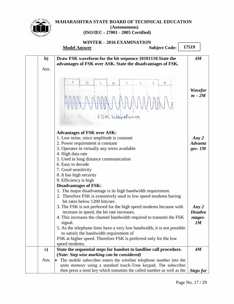
MAHARASHTRA STATE BOARD OF TECHNICAL EDUCATION (Autonomous) (ISO/IEC - 27001 - 2005 Certified) WINTER – 2016 EXAMINATION Model Answer Subject Code: Page No. 1 / 29 17519 Important Instructions to examiners: 1) The answers should be examined by key words and not as word-to-word as given in the model answer scheme. 2) The model answer and the answer written by candidate may vary but the examiner may try to assess the understanding level of the candidate. 3) The language errors such as grammatical, spelling errors should not be given more importance (Not applicable for subject English and Communication Skills). 4) While assessing figures, examiner may give credit for principal components indicated in the figure. The figures drawn by candidate and model answer may vary. The examiner may give credit for any equivalent figure drawn. 5) Credits may be given step wise for numerical problems. In some cases, the assumed constant values may vary and there may be some difference in the candidate‟s answers and model answer. 6) In case of some questions credit may be given by judgement on part of examiner of relevant answer based on candidate‟s understanding. 7) For programming language papers, credit may be given to any other program based on equivalent concept. Q.N o. Sub Q.N. Answer Marking Scheme 1. a) i) Ans. Attempt any three of the following: Draw and explain the block diagram of communication system. Fig: block diagram of communication system The main components of a basic communication system are: 1. Information or input signal 3x4=12 4M 2M block diagram
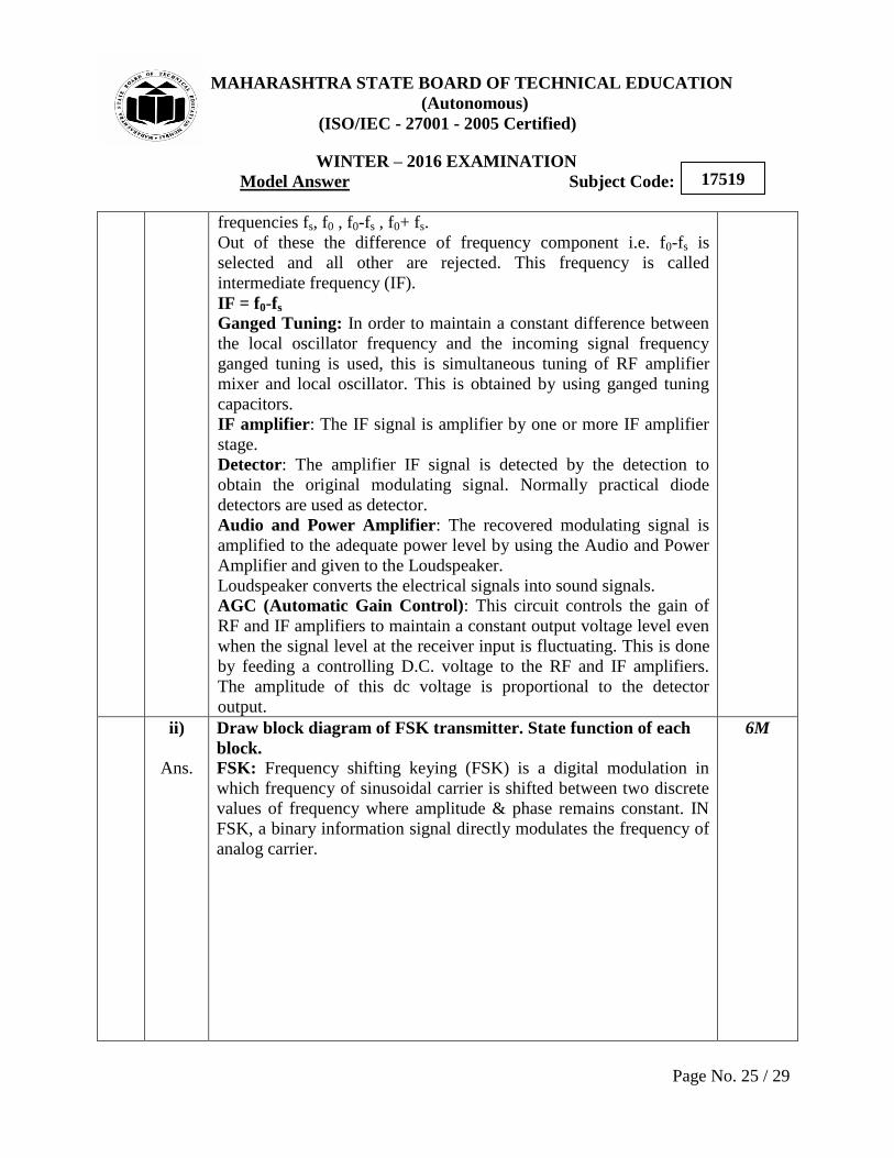
Transcript
MAHARASHTRA STATE BOARD OF TECHNICAL EDUCATION
(Autonomous)
(ISO/IEC - 27001 - 2005 Certified)
WINTER – 2016 EXAMINATION
Model Answer Subject Code:
Page No. 1 / 29
17519
Important Instructions to examiners:
1) The answers should be examined by key words and not as word-to-word as given in the model
answer scheme.
2) The model answer and the answer written by candidate may vary but the examiner may try to
assess the understanding level of the candidate.
3) The language errors such as grammatical, spelling errors should not be given more importance
(Not applicable for subject English and Communication Skills).
4) While assessing figures, examiner may give credit for principal components indicated in the
figure. The figures drawn by candidate and model answer may vary. The examiner may give
credit for any equivalent figure drawn.
5) Credits may be given step wise for numerical problems. In some cases, the assumed constant
values may vary and there may be some difference in the candidate‟s answers and model
answer.
6) In case of some questions credit may be given by judgement on part of examiner of relevant
answer based on candidate‟s understanding.
7) For programming language papers, credit may be given to any other program based on
equivalent concept.
Q.N
o.
Sub
Q.N.
Answer Marking
Scheme
1. a)
i)
Ans.
Attempt any three of the following:
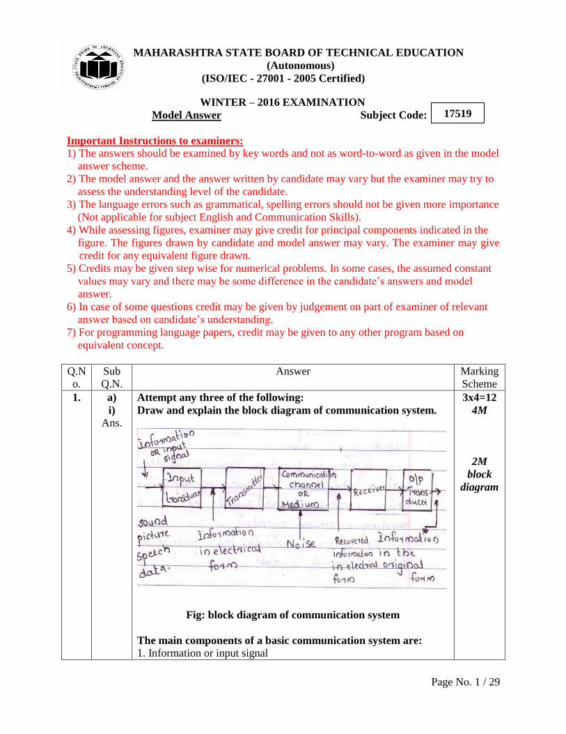
Draw and explain the block diagram of communication system.
Fig: block diagram of communication system
The main components of a basic communication system are:
1. Information or input signal
3x4=12
4M
2M
block
diagram
MAHARASHTRA STATE BOARD OF TECHNICAL EDUCATION
(Autonomous)
(ISO/IEC - 27001 - 2005 Certified)
WINTER – 2016 EXAMINATION
Model Answer Subject Code:
Page No. 2 / 29
17519
2. Input transducer
3. Transmitter
4. Communication channel or medium
5. Noise
6. Receiver
7. Output transducer
1. Information or input signal: The information can be in the form
of a sound signal like speech or music or it can be in the form of
pictures (T. V. signals) or it can be data information coming from a
computer.
2. Input Transducer: The communication system transmits
information in the form of electrical signals. The transducers convert
the non-electrical energy into its electrical energy called signals.
E.g. During a telephone conversation the words are in the form of
sound energy. The microphone converts sound signals into its
corresponding electrical signals.
TV camera converts the picture signals into electrical signals.
E.g. Microphone, TV, Camera.
3. Transmitter: It is used to convert the information into a signal
suitable for transmission over a given communication medium. It
increases the power level of the signal. The power level is increased
to cover a large range. The transmitter consists of electronic circuits
such as amplifier, mixer oscillator and power amplifier.
4. Communication channel or medium: The communication
channel is the medium used for transmission of electrical signals from
one place to other. The communication medium can be conducting
wires cables optical fiber or free space. Depending on the type of
communication medium two types of communication systems will
exist.
They are
1. Wire communication or line communication
2. Wireless communication or radio communication.
5. Noise: Noise is random undesirable electric energy that enters the
communication system through the communication medium and
interferes with the transmitted signal.
6. Receiver: The reception is exactly the opposite process of
2M
explanat
ion
MAHARASHTRA STATE BOARD OF TECHNICAL EDUCATION
(Autonomous)
(ISO/IEC - 27001 - 2005 Certified)
WINTER – 2016 EXAMINATION
Model Answer Subject Code:
Page No. 3 / 29
17519
transmission. The received signal is amplified demodulated converted
into a suitable form by the receiver. The receiver consists of
electronic circuits like mixer, oscillator, detector amplifier etc.
7. Output Transducer: The output transducer converts the electrical
signal at the output of the receiver back to the original form is sound
or TV pictures etc.
E.g. Loud speaker: electrical signals sound
Picture tubes: electrical signals visual data.
ii)
Ans.
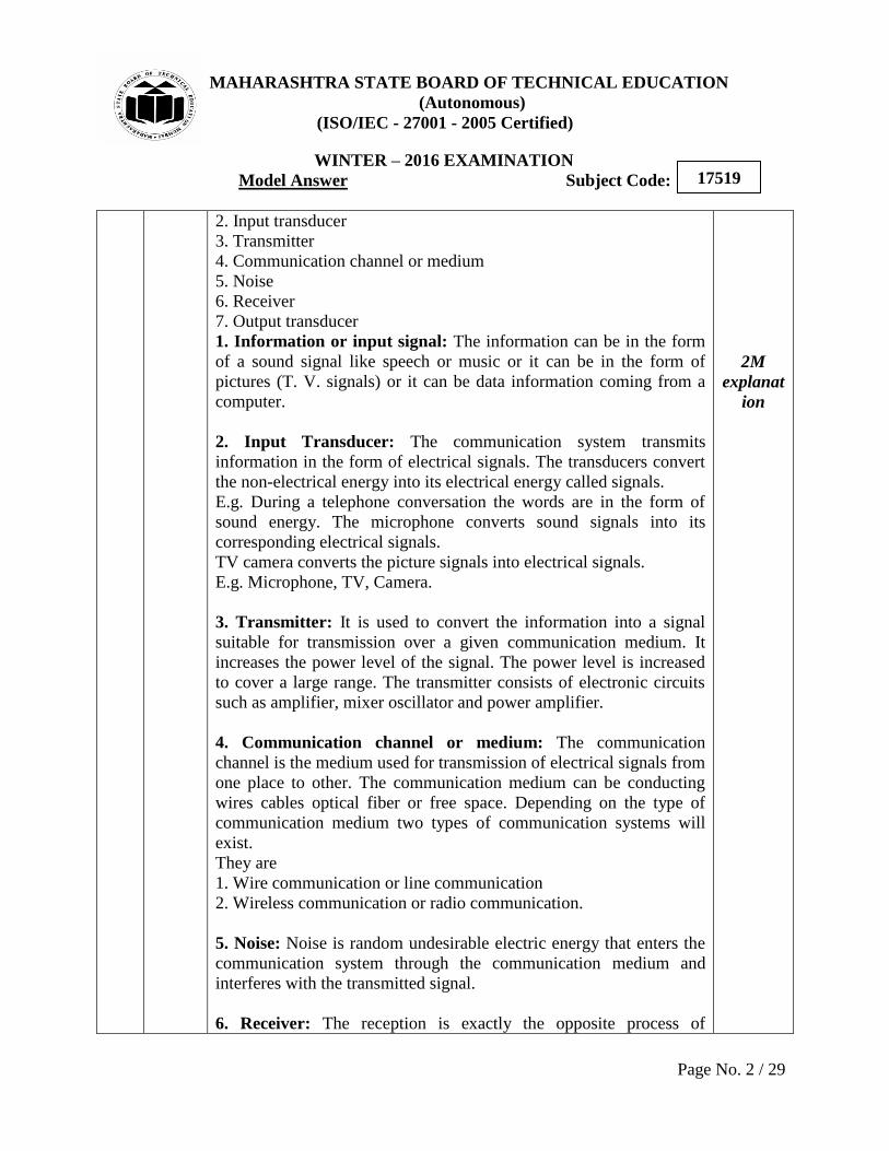
Define Modulation index for AM. Draw waveforms for m=1,
m>1, m<1.
Definition:
Modulation index: It is the ratio of amplitude of modulating signal
to the amplitude of carrier signal.
Modulation Index ( ) =(Vmax-Vmin)/(Vmax +Vmin)
1) m=1
2) m>1
3) m<1
4M
Definitio
n 1M
Diagram
of
wavefor
ms 1M
each
MAHARASHTRA STATE BOARD OF TECHNICAL EDUCATION
(Autonomous)
(ISO/IEC - 27001 - 2005 Certified)
WINTER – 2016 EXAMINATION
Model Answer Subject Code:
Page No. 4 / 29
17519
iii)
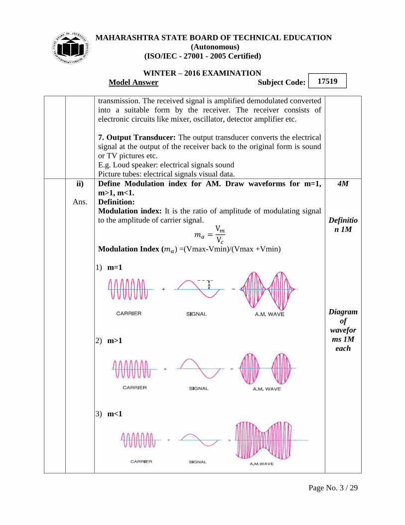
Ans. Compare between FSK and PSK (any four points).
Parameter FSK PSK
Definition In this technique,
frequency of the RF
carrier is varied in
accordance with
baseband
digital input signal.
In this technique, phase
of the RF carrier is varied
in accordance with
baseband digital input
signal.
Band Width 4fb ( ) fb=bit frequency
fb
fb=bit frequency
Noise
immunity
High compared to
ASK
High compared to ASK
Waveforms
Bit rate Suitable upto 1200
bits/sec
Suitable upto 180 bits/sec
4M
Any
four
points
1M each
iv)
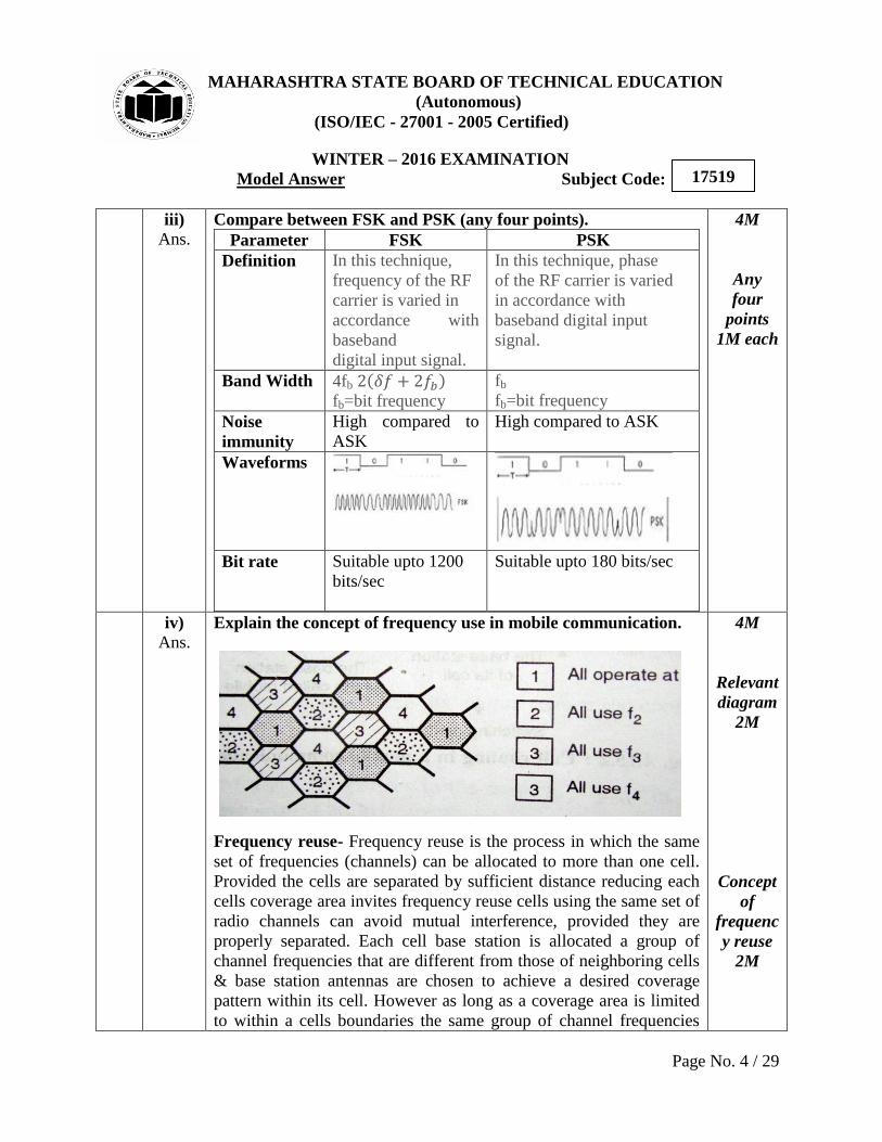
Ans. Explain the concept of frequency use in mobile communication.
Frequency reuse- Frequency reuse is the process in which the same
set of frequencies (channels) can be allocated to more than one cell.
Provided the cells are separated by sufficient distance reducing each
cells coverage area invites frequency reuse cells using the same set of
radio channels can avoid mutual interference, provided they are
properly separated. Each cell base station is allocated a group of
channel frequencies that are different from those of neighboring cells
& base station antennas are chosen to achieve a desired coverage
pattern within its cell. However as long as a coverage area is limited
to within a cells boundaries the same group of channel frequencies
4M
Relevant
diagram
2M
Concept
of
frequenc
y reuse
2M
MAHARASHTRA STATE BOARD OF TECHNICAL EDUCATION
(Autonomous)
(ISO/IEC - 27001 - 2005 Certified)
WINTER – 2016 EXAMINATION
Model Answer Subject Code:
Page No. 5 / 29
17519
may be used in different cells without interfacing with each other
provided the two cells are sufficient distance from one another.
1. b)
i)
Ans.
Attempt any one of the following:
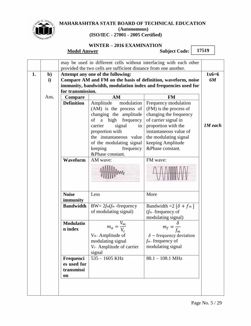
Compare AM and FM on the basis of definition, waveform, noise
immunity, bandwidth, modulation index and frequencies used for
for transmission.
Compare AM FM
Definition Amplitude modulation
(AM) is the process of
changing the amplitude
of a high frequency
carrier signal in
proportion with
the instantaneous value
of the modulating signal
keeping frequency
&Phase constant.
Frequency modulation
(FM) is the process of
changing the frequency
of carrier signal in
proportion with the
instantaneous value of
the modulating signal
keeping Amplitude
&Phase constant.
Waveform AM wave:
FM wave:
Noise
immunity
Less More
Bandwidth BW= 2fm(fm -frequency
of modulating signal) Bandwidth =2 [ ] (fm - frequency of
modulating signal)
Modulatio
n index
Vm - Amplitude of
modulating signal
Vc- Amplitude of carrier
signal
fm - frequency of
modulating signal
Frequenci
es used for
transmissi
on
535 – 1605 KHz 88.1 – 108.1 MHz
1x6=6
6M
1M each
MAHARASHTRA STATE BOARD OF TECHNICAL EDUCATION
(Autonomous)
(ISO/IEC - 27001 - 2005 Certified)
WINTER – 2016 EXAMINATION
Model Answer Subject Code:
Page No. 6 / 29
17519
ii)
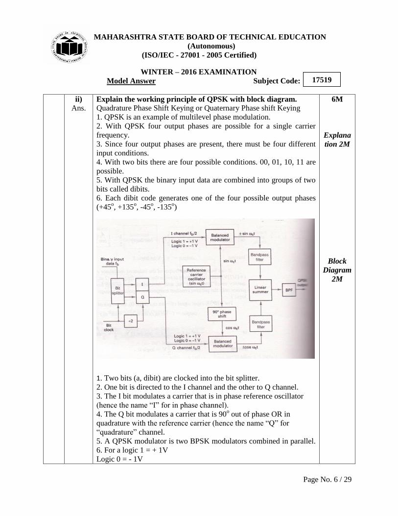
Ans. Explain the working principle of QPSK with block diagram.
Quadrature Phase Shift Keying or Quaternary Phase shift Keying
1. QPSK is an example of multilevel phase modulation.
2. With QPSK four output phases are possible for a single carrier
frequency.
3. Since four output phases are present, there must be four different
input conditions.
4. With two bits there are four possible conditions. 00, 01, 10, 11 are
possible.
5. With QPSK the binary input data are combined into groups of two
bits called dibits.
6. Each dibit code generates one of the four possible output phases
(+45o, +135
o, -45
o, -135
o)
1. Two bits (a, dibit) are clocked into the bit splitter.
2. One bit is directed to the I channel and the other to Q channel.
3. The I bit modulates a carrier that is in phase reference oscillator
(hence the name “I” for in phase channel).
4. The Q bit modulates a carrier that is 90o out of phase OR in
quadrature with the reference carrier (hence the name “Q” for
“quadrature” channel.
5. A QPSK modulator is two BPSK modulators combined in parallel.
6. For a logic 1 = + 1V
Logic 0 = - 1V
6M
Explana
tion 2M
Block
Diagram
2M
MAHARASHTRA STATE BOARD OF TECHNICAL EDUCATION
(Autonomous)
(ISO/IEC - 27001 - 2005 Certified)
WINTER – 2016 EXAMINATION
Model Answer Subject Code:
Page No. 7 / 29
17519
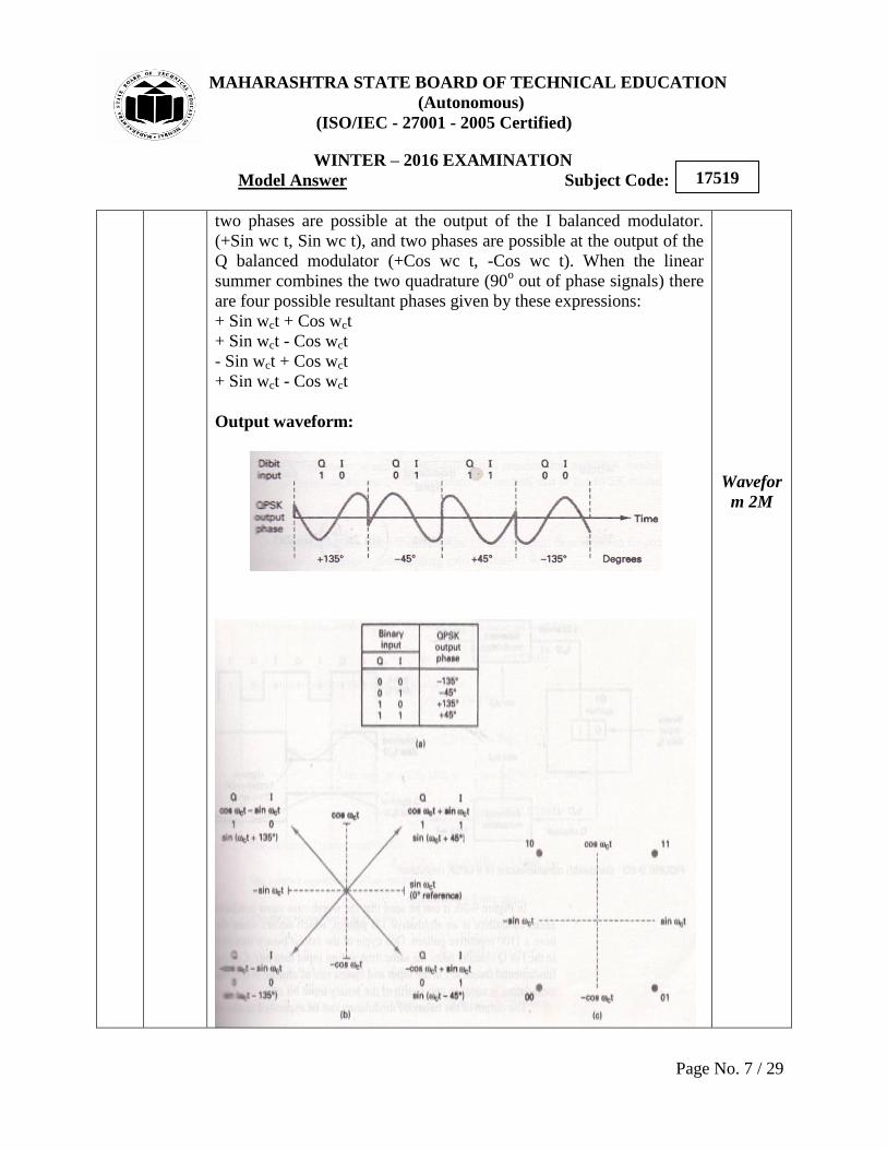
two phases are possible at the output of the I balanced modulator.
(+Sin wc t, Sin wc t), and two phases are possible at the output of the
Q balanced modulator (+Cos wc t, -Cos wc t). When the linear
summer combines the two quadrature (90o out of phase signals) there
are four possible resultant phases given by these expressions:
+ Sin wct + Cos wct
+ Sin wct - Cos wct
- Sin wct + Cos wct
+ Sin wct - Cos wct
Output waveform:
Wavefor
m 2M
MAHARASHTRA STATE BOARD OF TECHNICAL EDUCATION
(Autonomous)
(ISO/IEC - 27001 - 2005 Certified)
WINTER – 2016 EXAMINATION
Model Answer Subject Code:
Page No. 8 / 29
17519
2.
a)
Ans.
Attempt any four of the following:
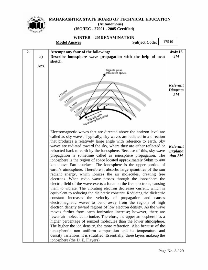
Describe ionosphere wave propagation with the help of neat
sketch.
Electromagnetic waves that are directed above the horizon level are
called as sky waves. Typically, sky waves are radiated in a direction
that produces a relatively large angle with reference to earth. Sky
waves are radiated toward the sky, where they are either reflected or
refracted back to earth by the ionosphere. Because of this, sky wave
propagation is sometime called as ionosphere propagation. The
ionosphere is the region of space located approximately 50km to 400
km above Earth surface. The ionosphere is the upper portion of
earth‟s atmosphere. Therefore it absorbs large quantities of the sun
radiant energy, which ionizes the air molecules, creating free
electrons. When radio wave passes through the ionosphere the
electric field of the wave exerts a force on the free electrons, causing
them to vibrate. The vibrating electron decreases current, which is
equivalent to reducing the dielectric constant. Reducing the dielectric
constant increases the velocity of propagation and causes
electromagnetic waves to bend away from the regions of high
electron density toward regions of low electron density. As the wave
moves farther from earth ionization increase; however, there are
fewer air molecules to ionize. Therefore, the upper atmosphere has a
higher percentage of ionized molecules than the lower atmosphere.
The higher the ion density, the more refraction. Also because of the
ionosphere‟s non uniform composition and its temperature and
density variations, it is stratified. Essentially, three layers makeup the
ionosphere (the D, E, Flayers).
4x4=16
4M
Relevant
Diagram
2M
Relevant
Explana
tion 2M
MAHARASHTRA STATE BOARD OF TECHNICAL EDUCATION
(Autonomous)
(ISO/IEC - 27001 - 2005 Certified)
WINTER – 2016 EXAMINATION
Model Answer Subject Code:
Page No. 9 / 29
17519
b)
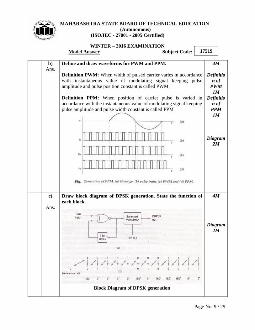
Ans. Define and draw waveforms for PWM and PPM.
Definition PWM: When width of pulsed carrier varies in accordance
with instantaneous value of modulating signal keeping pulse
amplitude and pulse position constant is called PWM.
Definition PPM: When position of carrier pulse is varied in
accordance with the instantaneous value of modulating signal keeping
pulse amplitude and pulse width constant is called PPM
4M
Definitio
n of
PWM
1M
Definitio
n of
PPM
1M
Diagram
2M
c)
Ans.
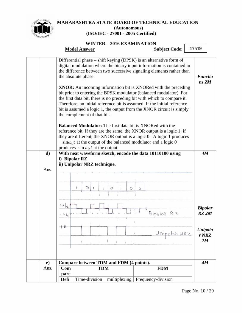
Draw block diagram of DPSK generation. State the function of
each block.
Block Diagram of DPSK generation
4M
Diagram
2M
MAHARASHTRA STATE BOARD OF TECHNICAL EDUCATION
(Autonomous)
(ISO/IEC - 27001 - 2005 Certified)
WINTER – 2016 EXAMINATION
Model Answer Subject Code:
Page No. 10 / 29
17519
Differential phase – shift keying (DPSK) is an alternative form of
digital modulation where the binary input information is contained in
the difference between two successive signaling elements rather than
the absolute phase.
XNOR: An incoming information bit is XNORed with the preceding
bit prior to entering the BPSK modulator (balanced modulator). For
the first data bit, there is no preceding bit with which to compare it.
Therefore, an initial reference bit is assumed. If the initial reference
bit is assumed a logic 1, the output from the XNOR circuit is simply
the complement of that bit.
Balanced Modulator: The first data bit is XNORed with the
reference bit. If they are the same, the XNOR output is a logic 1; if
they are different, the XNOR output is a logic 0. A logic 1 produces
+ sin at the output of the balanced modulator and a logic 0
produces- sin at the output.
Functio
ns 2M
d)
Ans.
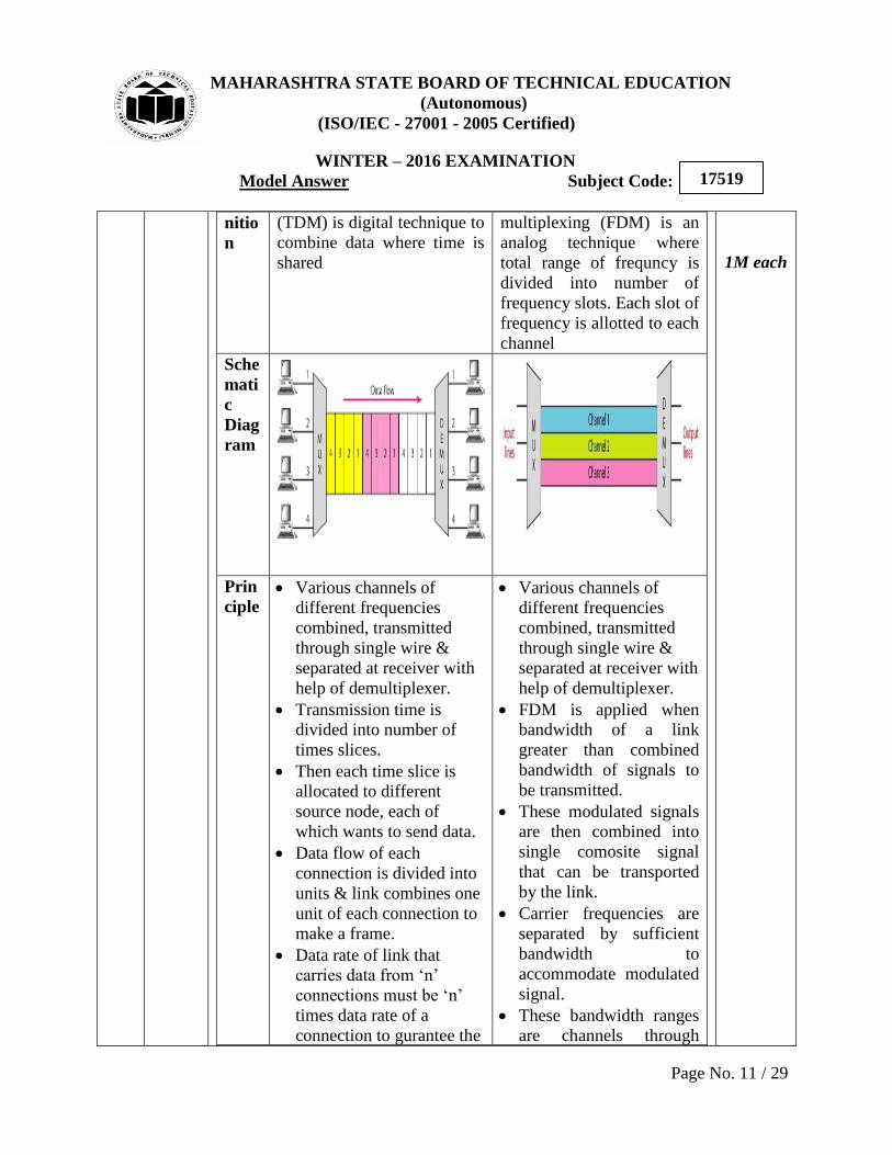
With neat waveform sketch, encode the data 10110100 using