Page 1
MAHARASHTRA STATE BOARD OF TECHNICAL EDUCATION 17431
(Autonomous)
(ISO/IEC - 27001 - 2005 Certified)
_________________________________________________________________________________________________________________
17731 Page 1
WINTER– 16 EXAMINATION (Subject Code: 17431) Model Answer
Important Instructions to examiners:
1) The answers should be examined by key words and not as word-to-word as given in the model answer
scheme.
2) The model answer and the answer written by candidate may vary but the examiner may try to assess the
understanding level of the candidate.
3) The language errors such as grammatical, spelling errors should not be given more Importance (Not
applicable for subject English and Communication Skills.
4) While assessing figures, examiner may give credit for principal components indicated in the figure. The
figures drawn by candidate and model answer may vary. The examiner may give credit for any equivalent
figure drawn.
5) Credits may be given step wise for numerical problems. In some cases, the assumed constant values may
vary and there may be some difference in the candidate’s answers and model answer.
6) In case of some questions credit may be given by judgement on part of examiner of relevant answer based
on candidate’s understanding. 7) For programming language papers, credit may be given to any other program based on equivalent concept.
Q. No.
Sub Q.N.
Answer Marking Scheme
Q.1 a) Attempt any SIX of following 12-Total Marks
1
i) Describe the four salient features of 8085.
2 M
Ans: Features of 8085:
1. 16 address line so 216=64 Kbytes of memory can be addressed.
2. Operating clock frequency is 3MHz and minimum clock frequency is 500 KHz.
3. On chip bus controller.
4. Provide 74 instructions with five addressing modes.
5. 8085 is 8 bit microprocessor.
6. Provides 5 level hardware interrupts and 8 software interrupts.
7. It can generate 8 bit I/O address so 28 =256 input and 256 output ports can be
accessed.
8. Requires a single +5 Volts power supply.
9. Requires 2 phase, 50% duty cycle TTL clock
10. Provide 2 serial I/O lines, so peripheral can be interfaced with 8085 μp.
Any Four
Features
[½ Mark
each]
ii) State the function of following pins of 8086.
1) ALE
2) WR
2 M
Ans: 1) ALE-
This output signal is used to indicate availability of valid address on address/data
lines and is connected to latch enable input of latches (8282 or 74LS373) .This
signal is active high and never tristate.
(1 Mark
each)
Page 2
MAHARASHTRA STATE BOARD OF TECHNICAL EDUCATION 17431
(Autonomous)
(ISO/IEC - 27001 - 2005 Certified)
_________________________________________________________________________________________________________________
17731 Page 2
2) WR
The signal write WR indicates that a write bus cycle is in progress. The 8086
switches WR to logic 0 to signal external device that valid write or output data are
on the bus.
iii) Explain the functions of following instruction with one example.
1) XLAT
2) LEA
2 M
Ans: 1) XLAT
XLAT replaces a byte in AL register with a byte from 256 byte lookup table
beginning at [BX] .
AL is used as offset into this table.
Operation :- AL[BX+AL]
2) LEA- This instruction indicates the offset of the variable or memory location named as
the source and put this offset in the indicated 16 – bit register. Example: LEA BX, PRICE ; Load BX with offset of PRICE in DS
(1 Mark
each)
iv) Define the terms: algorithm and flowchart.
2 M
Ans: Algorithm: The formula or sequence of operations to be performed by the program can
be specified as a step in general English is called algorithm.
Flowchart: The flowchart is a graphically representation of the program operation or
task.
(Correct
Definition: 1
Mark each)
v) List maskable and non-maskable interrupts of 8085. 2 M
Ans: Maskable Interrupt : TRAP
Non-maskable Interrupts : INTR, RST 7.5, RST 6.5, RST 5.5
(Maskable Interrupt :1 Mark) (Non-Maskable interrupt :ANY 2 : ½ Mark each)
vi) List any four features of 8086.
2 M
Page 3
MAHARASHTRA STATE BOARD OF TECHNICAL EDUCATION 17431
(Autonomous)
(ISO/IEC - 27001 - 2005 Certified)
_________________________________________________________________________________________________________________
17731 Page 3
Ans: 1) It is a 16 bit µp.
2) 8086 has a 20 bit address bus can access upto 220 memory locations ( 1 MB) .
3) It can support upto 64K I/O ports.
4) It provides 16-bit registers. AX,BX,CX,DX,CS,SS,DS,ES,BP,SP,SI,DI,IP & FLAG
REGISTER
5) It has multiplexed address and data bus AD0- AD15 and A16 – A19.
6) It requires single phase clock with 33% duty cycle to provide internal timing
7) 8086 is designed to operate in two modes, Minimum and Maximum.
8) It can prefetches up to 6 instruction bytes from memory and queues them in order to
speed up instruction execution.
9) Interrupts:-8086 has 256 vectored interrupts.
10) Provides separate instructions for string manipulation.
11) Operating clock frequencies 5MHz, 8MHz, 10MHz.
(Any Four
Features –
½ Mark
each)
vii) State the functions of following directives
1) ProC
2) ENDP
2 M
Ans: 1) ProC - The ProC directive is used to identify the start of a procedure. The term near
or far is used to specify the type of the procedure.if the term is not specified , then
assembler assumes NEAR as a type Specifier.
General Form: Procedure_name PROC [NEAR/FAR]
2)ENDP The directive is used along with the name of the procedure to indicate the
end of a procedure to the assembler.
General Form : Procedure_name ENDP
(Correct
Function: 1
Mark each)
viii) Compare the following 8086 instructions:
AND and TEST (Any four points)
2 M
Ans Sr. No AND TEST
1 This instruction AND’s bit-
by-bit the source operand
with destination operand and
the result is stored in the
destination specified in the
instruction
This instruction AND’s the contents of
source byte or word with the contents of
specified destination byte or word and
flags are updated ,but neither operands
are changed.
(Correct comparison 4 points :2M)
Page 4
MAHARASHTRA STATE BOARD OF TECHNICAL EDUCATION 17431
(Autonomous)
(ISO/IEC - 27001 - 2005 Certified)
_________________________________________________________________________________________________________________
17731 Page 4
2 General Form:
AND
DESTINATION,SOURCE
General Form :
TEST DESTINATION,SOURCE
3 Ex:- AND BH,CL Ex:- TEST BH,CL
4 Flag affected: PF,SF,ZF Flag affected: CF, OF, PF,SF,ZF
b) Attempt any TWO of following: 8 M 8 M
i) Describe the functions of the following directives:
1) DD
2) DB
3) INCLUDE
4) DUP
4 M
Ans: 1) DD - (Define Double Word or Data Double Word)
• This is used to define a double word (32-bit) type variable.
• The range of values : 0 to 232 - 1 bits for unsigned numbers. -232-1 to +232-1 – 1 for
signed numbers
• This can be used to define a single double word or multiple double word.
2) DB - Define byte (8 bits)
• It is used to declare a byte type variable of 8 bit. It also can be used to declare an
array of bytes.
• The range of values that can be stored in a byte is 0 to 255 for unsigned numbers
and –128 +127 for signed numbers.
3) INCLUDE –
• This INCLUDE directive is used to insert a block of source code from the named
file into the current source module.
• The directive INCLUDE informs the assembler to include the statement defined
in the include file. The name of the include file follows the statement INCLUDE.
4) DUP: Duplicate memory location:-
• This directive can be used to generate multiple bytes or words with known as well
as un-initialized values.
(Correct
Use of each
:1 Mark )
ii) Describe Linker and Debugger with respect to their functions and usages 4 M
Ans: Linker:
1. It is a programming tool used to convert Object code into executable program
called .EXE module.
2. It combines, if requested, more than one separated assembled modules into one
executable module such as two or more assembly programs or an assembly
language with C program.
(Description
: 2 Mark
each)
Page 5
MAHARASHTRA STATE BOARD OF TECHNICAL EDUCATION 17431
(Autonomous)
(ISO/IEC - 27001 - 2005 Certified)
_________________________________________________________________________________________________________________
17731 Page 5
Debugger: -
1. Debugger is a program that allows the execution of program in single step mode
under the control of the user.
2. The errors in program can be located and corrected using a debugger.
iii) Write an ALP to find sum of 10 numbers.
(Assume numbers as 8 bits)
4 M
Ans:
CODE SEGMENT START :ASSUME CS:CODE,DS:DATA MOV DX,DATA MOV DS,DX MOV CL,10 ; COUNTER 10d or 0AH MOV SI,OFFSET NUM1 UP:MOV AL,[SI] ADD RESULT,AL JNC NEXT
INC CARRY NEXT:INC SI
LOOP UP MOV AX,4C00H INT 21H CODE ENDS DATA SEGMENT NUM DB 05H,06H,03H,04H,02H,07H,02H,01H,08H,09H RESULT DB 1 DUP(0) CARRY DB 0H DATA ENDS END START
(Correct
Program -4
Marks,(
Any other
logic may be
considered)
Q 2 Attempt any FOUR of the following:
16 M
a) Draw the flag register of 8085 and explain the function of : i. Auxilliary carry flag and
ii. Carry flag
4M
Ans:
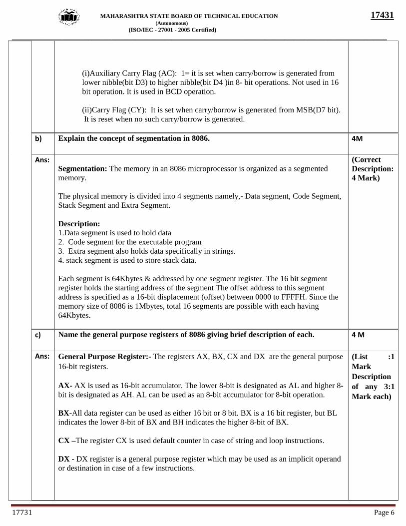
Flags of 8085: ALU contains 5 flip-flop, which are set or reset after operation, according
to data , conditions of result.
(Diagram: 2
Mark,
Description
of each flag
: 1 Mark
each)
Page 6
MAHARASHTRA STATE BOARD OF TECHNICAL EDUCATION 17431
(Autonomous)
(ISO/IEC - 27001 - 2005 Certified)
_________________________________________________________________________________________________________________
17731 Page 6
(i)Auxiliary Carry Flag (AC): 1= it is set when carry/borrow is generated from
lower nibble(bit D3) to higher nibble(bit D4 )in 8- bit operations. Not used in 16
bit operation. It is used in BCD operation.
(ii)Carry Flag (CY): It is set when carry/borrow is generated from MSB(D7 bit).
It is reset when no such carry/borrow is generated.
b) Explain the concept of segmentation in 8086.
4M
Ans:
Segmentation: The memory in an 8086 microprocessor is organized as a segmented
memory.
The physical memory is divided into 4 segments namely,- Data segment, Code Segment,
Stack Segment and Extra Segment.
Description:
1.Data segment is used to hold data
2. Code segment for the executable program
3. Extra segment also holds data specifically in strings.
4. stack segment is used to store stack data.
Each segment is 64Kbytes & addressed by one segment register. The 16 bit segment
register holds the starting address of the segment The offset address to this segment
address is specified as a 16-bit displacement (offset) between 0000 to FFFFH. Since the
memory size of 8086 is 1Mbytes, total 16 segments are possible with each having
64Kbytes.
(Correct
Description:
4 Mark)
c) Name the general purpose registers of 8086 giving brief description of each. 4 M
Ans: General Purpose Register:- The registers AX, BX, CX and DX are the general purpose
16-bit registers.
AX- AX is used as 16-bit accumulator. The lower 8-bit is designated as AL and higher 8-
bit is designated as AH. AL can be used as an 8-bit accumulator for 8-bit operation.
BX-All data register can be used as either 16 bit or 8 bit. BX is a 16 bit register, but BL
indicates the lower 8-bit of BX and BH indicates the higher 8-bit of BX.
CX –The register CX is used default counter in case of string and loop instructions.
DX - DX register is a general purpose register which may be used as an implicit operand
or destination in case of a few instructions.
(List :1
Mark
Description
of any 3:1
Mark each)
Page 7
MAHARASHTRA STATE BOARD OF TECHNICAL EDUCATION 17431
(Autonomous)
(ISO/IEC - 27001 - 2005 Certified)
_________________________________________________________________________________________________________________
17731 Page 7
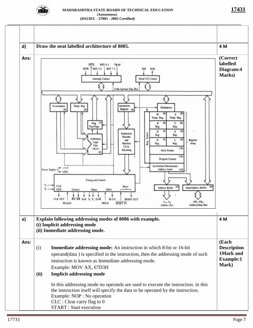
d) Draw the neat labelled architecture of 8085.
4 M
Ans:
(Correct
labelled
Diagram:4
Marks)
e) Explain following addressing modes of 8086 with example.
(i) Implicit addressing mode
(ii) Immediate addressing mode.
4 M
Ans:
(i) Immediate addressing mode: An instruction in which 8-bit or 16-bit
operand(data ) is specified in the instruction, then the addressing mode of such
instruction is known as Immediate addressing mode.
Example: MOV AX, 67D3H
(ii) Implicit addressing mode
In this addressing mode no operands are used to execute the instruction. in this
the instruction itself will specify the data to be operated by the instruction.
Example: NOP : No operation
CLC : Clear carry flag to 0
START : Start execution
(Each
Description
1Mark and
Example:1
Mark)
Page 8
MAHARASHTRA STATE BOARD OF TECHNICAL EDUCATION 17431
(Autonomous)
(ISO/IEC - 27001 - 2005 Certified)
_________________________________________________________________________________________________________________
17731 Page 8
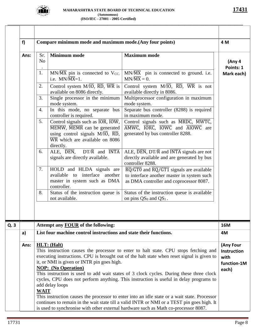
f) Compare minimum mode and maximum mode.(Any four points)
4 M
Ans: Sr.
No
.
Minimum mode Maximum mode
1. MN/MX̅̅ ̅̅ pin is connected to VCC.
i.e. MN/MX̅̅ ̅̅ =1.
MN/MX̅̅ ̅̅ pin is connected to ground. i.e.
MN/MX̅̅ ̅̅ = 0.
2. Control system M/IO̅̅̅, RD̅̅ ̅̅ , WR̅̅ ̅̅ ̅ is
available on 8086 directly.
Control system M/IO̅̅̅, RD̅̅ ̅̅ , WR̅̅ ̅̅ ̅ is not
available directly in 8086.
3. Single processor in the minimum
mode system.
Multiprocessor configuration in maximum
mode system.
4. In this mode, no separate bus
controller is required.
Separate bus controller (8288) is required
in maximum mode.
5. Control signals such as IOR̅̅ ̅̅ ̅, IOW̅̅ ̅̅ ̅̅ ,
MEMW̅̅ ̅̅ ̅̅ ̅̅ ̅̅ , MEMR̅̅ ̅̅ ̅̅ ̅̅ ̅ can be generated
using control signals M/IO̅̅̅, RD̅̅ ̅̅ ,
WR̅̅ ̅̅ ̅ which are available on 8086
directly.
Control signals such as MRDC̅̅ ̅̅ ̅̅ ̅̅ , MWTC̅̅ ̅̅ ̅̅ ̅̅ ̅,
AMWC̅̅ ̅̅ ̅̅ ̅̅ ̅, IORC̅̅ ̅̅ ̅̅ ̅, IOWC̅̅ ̅̅ ̅̅ ̅̅ and AIOWC̅̅ ̅̅ ̅̅ ̅̅ ̅ are
generated by bus controller 8288.
6. ALE, DEN̅̅ ̅̅ ̅̅ , DT/R̅ and INTA̅̅ ̅̅ ̅̅ ̅
signals are directly available.
ALE, DEN̅̅ ̅̅ ̅̅ , DT/R̅ and INTA̅̅ ̅̅ ̅̅ ̅ signals are not
directly available and are generated by bus
controller 8288.
7. HOLD and HLDA signals are
available to interface another
master in system such as DMA
controller.
RQ̅̅ ̅̅ /GT0̅̅ ̅̅ ̅ and RQ/̅̅ ̅̅ ̅̅ GT1̅̅ ̅̅ ̅ signals are available
to interface another master in system such
as DMA controller and coprocessor 8087.
8. Status of the instruction queue is
not available.
Status of the instruction queue is available
on pins QS0 and QS1 .
(Any 4
Points: 1 Mark each)
Q. 3 Attempt any FOUR of the following: 16M
a) List four machine control instructions and state their functions.
4M
Ans: HLT: (Halt) This instruction causes the processor to enter to halt state. CPU stops fetching and
executing instructions. CPU is brought out of the halt state when reset signal is given to
it, or NMI is given or INTR pin goes high.
NOP: (No Operation) This instruction is used to add wait states of 3 clock cycles. During these three clock
cycles, CPU does not perform anything. This instruction is useful in delay programs to
add delay loops
WAIT This instruction causes the processor to enter into an idle state or a wait state. Processor
continues to remain in the wait state till a valid INTR or NMI or a TEST pin goes high. It
is used to synchronise with other external hardware such as Math co-processor 8087.
(Any Four Instruction with function-1M each)
Page 9
MAHARASHTRA STATE BOARD OF TECHNICAL EDUCATION 17431
(Autonomous)
(ISO/IEC - 27001 - 2005 Certified)
_________________________________________________________________________________________________________________
17731 Page 9
LOCK This instruction causes the processor to take control of the shared resources. This is used
as an instruction prefix to some critical instructions which has to be executed. While
LOCKED, it prevents the resources to be shared by other processors.
ESC
This instruction is used to pass instructions to a coprocessor, such as the 8087 Math
coprocessor, which shares the address and data bus with 8086. Instructions for the
coprocessor are represented by a 6-bit code embedded in the ESC instruction.
b) Describe how 20 bit physical address is formed in 8086 microprocessor with one
suitable example. 4M
Ans: Generation of 20 bit physical address in 8086 :- Segment registers carry 16 bit data,
which is also known as base address. BIU appends four 0 bits to LSB of the base address.
This address becomes 20-bit address. Any base/pointer or index register carries 16 bit
offset. Offset address is added into 20-bit base address which finally forms 20 bit
physical address of memory location.
Example :
Given CS = 3500H and IP = 1234H
The given code segment base address is appended by four 0 bits. And IP offset is added
to it.
CS 35000 H ……… 0 is appended by BIU (or Hardwired zero)
IP + 1234 H
-------------------
36234 H
(Description
:2Marks;
Example:2
Marks)
(Any other
example can
be
considered)
c) Draw and explain the architecture of 8288 Bus Controller.
4M
Ans: 1) The bus controller chip has input lines S2, S1, S0 and CLK. These inputs to 8288
are driven by CPU.
2) It derives the outputs ALE, DEN, DT/R, MRDC̅̅ ̅̅ ̅̅ ̅̅ , MWTC̅̅ ̅̅ ̅̅ ̅̅ ̅, AMWC̅̅ ̅̅ ̅̅ ̅̅ ̅, IORC̅̅ ̅̅ ̅̅ ̅,
IOWC ̅̅ ̅̅ ̅̅ ̅̅ and AIOWC̅̅ ̅̅ ̅̅ ̅̅ ̅. The AEN̅̅ ̅̅ ̅̅ , IOB and CEN pins are specially useful for
multiprocessor systems.
3) AEN̅̅ ̅̅ ̅̅ and IOB are generally grounded. CEN pin is usually tied to +5V. The
significance of the MCE/ PDEN̅̅ ̅̅ ̅̅ ̅̅ output depends upon the status of the IOB pin.
4) If IOB is grounded, it acts as master cascade enable to control cascade 8259A,
else it acts as peripheral data enable used in the multiple bus configurations.
5) INTA pin used to issue two interrupt acknowledge pulses to the interrupt
controller or to an interrupting device.
6) IORC̅̅ ̅̅ ̅̅ ̅, IOWC̅̅ ̅̅ ̅̅ ̅̅ are I/O read command and I/O write command signals respectively.
These signals enable an IO interface to read or write the data from or to the
address port.
7) TheMRDC̅̅ ̅̅ ̅̅ ̅̅ , MWTC̅̅ ̅̅ ̅̅ ̅̅ ̅ are memory read command and memory write command
signals respectively and may be used as memory read or write signals.
8) All these command signals instructs the memory to accept or send data from or to
the bus.
9) For both of these write command signals, the advanced signals namely
AIOWCand AMWC̅̅ ̅̅ ̅̅ ̅̅ ̅are available.
(Description
:2Marks,
Diagram:2
Marks)
Page 10
MAHARASHTRA STATE BOARD OF TECHNICAL EDUCATION 17431
(Autonomous)
(ISO/IEC - 27001 - 2005 Certified)
_________________________________________________________________________________________________________________
17731 Page 10
d) Explain any four rotation instructions with example.
4M
Ans: Rotate instructions
ROR (Rotate Right without Carry)
Syntax :-- ROR destination, count
1) This instruction rotates the destination bit by bit to the right excluding the carry
2) The bit moved out of LSB is rotated around into the MSB and also copied to CF.
3) The count can be either 1 or specified by CL register.
4) The destination can be a byte or a word in register or a memory location, but not
an immediate data.
Operation Performed :--
MSB LSB CF
E.g: ROR
If CF = 0, BH = 54H
MOV CL, 02 ; Load CL register for the count
ROR BH, CL ; Rotate the contents of BH register by twice towards right
After two times ROR,
01010100 00101010 00010101 = 15H
ROL (Rotate Left without Carry)
Syntax :-- ROL destination, count
1) This instruction rotates the destination bit by bit to the left excluding the carry
2) The bit moved out of MSB is rotated around into the LSB and also copied to CF.
3) The count can be either 1 or specified by CL register.
4) The destination can be a byte or a word in register or a memory location, but not an
(Any four
instructions
with
example;
Each
1Mark)
Page 11
MAHARASHTRA STATE BOARD OF TECHNICAL EDUCATION 17431
(Autonomous)
(ISO/IEC - 27001 - 2005 Certified)
_________________________________________________________________________________________________________________
17731 Page 11
immediate data.
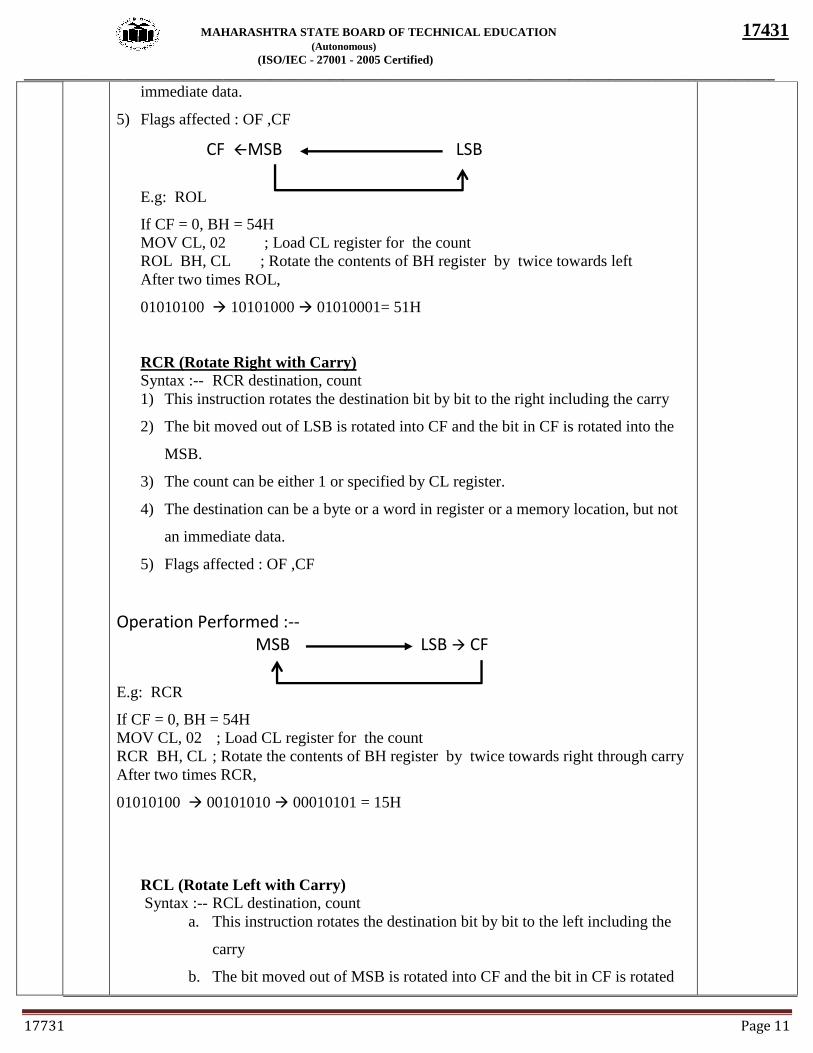
5) Flags affected : OF ,CF
CF MSB LSB
E.g: ROL
If CF = 0, BH = 54H
MOV CL, 02 ; Load CL register for the count
ROL BH, CL ; Rotate the contents of BH register by twice towards left
After two times ROL,
01010100 10101000 01010001= 51H
RCR (Rotate Right with Carry)
Syntax :-- RCR destination, count
1) This instruction rotates the destination bit by bit to the right including the carry
2) The bit moved out of LSB is rotated into CF and the bit in CF is rotated into the
MSB.
3) The count can be either 1 or specified by CL register.
4) The destination can be a byte or a word in register or a memory location, but not
an immediate data.
5) Flags affected : OF ,CF
Operation Performed :-- MSB LSB CF
E.g: RCR
If CF = 0, BH = 54H
MOV CL, 02 ; Load CL register for the count
RCR BH, CL ; Rotate the contents of BH register by twice towards right through carry
After two times RCR,
01010100 00101010 00010101 = 15H
RCL (Rotate Left with Carry)
Syntax :-- RCL destination, count
a. This instruction rotates the destination bit by bit to the left including the
carry
b. The bit moved out of MSB is rotated into CF and the bit in CF is rotated
Page 12
MAHARASHTRA STATE BOARD OF TECHNICAL EDUCATION 17431
(Autonomous)
(ISO/IEC - 27001 - 2005 Certified)
_________________________________________________________________________________________________________________
17731 Page 12
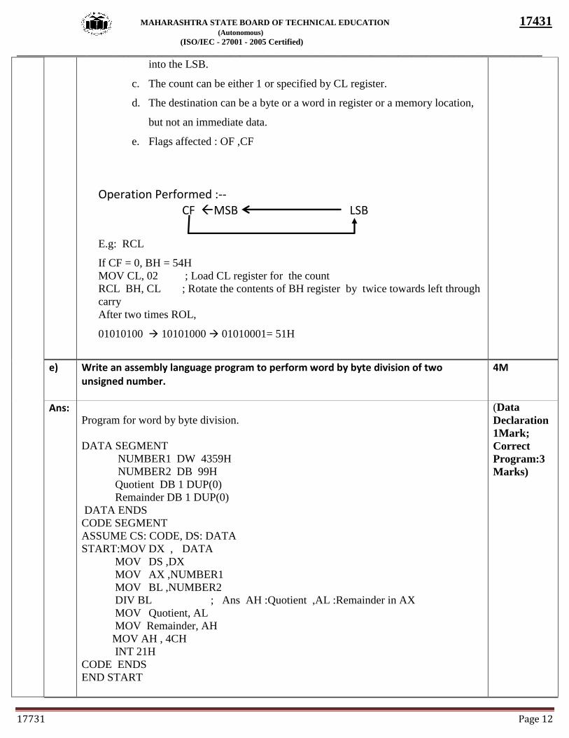
into the LSB.
c. The count can be either 1 or specified by CL register.
d. The destination can be a byte or a word in register or a memory location,
but not an immediate data.
e. Flags affected : OF ,CF
Operation Performed :--
CF MSB LSB
E.g: RCL
If CF = 0, BH = 54H
MOV CL, 02 ; Load CL register for the count
RCL BH, CL ; Rotate the contents of BH register by twice towards left through
carry
After two times ROL,
01010100 10101000 01010001= 51H
e) Write an assembly language program to perform word by byte division of two unsigned number.
4M
Ans:
Program for word by byte division.
DATA SEGMENT
NUMBER1 DW 4359H
NUMBER2 DB 99H
Quotient DB 1 DUP(0)
Remainder DB 1 DUP(0)
DATA ENDS
CODE SEGMENT
ASSUME CS: CODE, DS: DATA
START:MOV DX , DATA
MOV DS ,DX
MOV AX ,NUMBER1
MOV BL ,NUMBER2
DIV BL ; Ans AH :Quotient ,AL :Remainder in AX
MOV Quotient, AL
MOV Remainder, AH
MOV AH , 4CH
INT 21H
CODE ENDS
END START
(Data
Declaration
1Mark;
Correct
Program:3
Marks)
Page 13
MAHARASHTRA STATE BOARD OF TECHNICAL EDUCATION 17431
(Autonomous)
(ISO/IEC - 27001 - 2005 Certified)
_________________________________________________________________________________________________________________
17731 Page 13
f) Draw the neat interfacing diagram in minimum mode of 8086. 4M
Ans:
(Correct
labeled
Diagram :4
Mark)
Q. 4 Attempt any FOUR of following: 16 M
a) Write suitable example explain following instructions. (i)DAA (ii)ADC (iii)MUL (iv)XCHG
4 M
Ans: (i) (i) DAA (Decimal Adjust Accumulator)
Syntax :-- DAA
1. This instruction is used to convert the result of the addition of two packed BCD
numbers to a valid BCD number.
2. The result has to be only in AL.
3. After addition if the lower nibble is greater than 9 or AF =1, it will add 06H to the
lower nibble in AL.
4. After this addition, if the upper nibble is greater than 9 or if CF = 1, DAA instruction
adds 60H to AL.
5. DAA instruction affects AF,CF,PF and ZF. OF is undefined.
Operation Performed :--
6. If lower nibble of AL > 9 or AF =1 then AL = AL +06
7. If higher nibble of AL > 9 or CF =1 then AL = AL +60
Numeric Examples
AL = 53H, CL = 29H
ADD AL,CL ; AL AL + CL
;AL 53 + 29
;AL 7CH
DAA ; AL 7C +06 (as C>9)
;AL 82
(ii) ADC Destination, Source
(Each
Instruction:
1Mark)
Page 14
MAHARASHTRA STATE BOARD OF TECHNICAL EDUCATION 17431
(Autonomous)
(ISO/IEC - 27001 - 2005 Certified)
_________________________________________________________________________________________________________________
17731 Page 14
1) This instruction is used to add the contents of source to the destination and carry flag.
2) The result is stored in the destination.
3) The source operand can be a immediate, a register or a memory location addressed by
any of the 24 addressing modes.
4) The destination can be a register or a memory location, but not an immediate data.
5) Both operands cannot be immediate data or memory location.
6) The source and the destination must be of the same data type i.e., ADD instruction
adds a byte to byte or a word to word. It adds the two operands with CF.
It effects AF, CF, OF, PF, SF, ZF flags.
E.g.:
ADC AL, 74H
ADC DX, AX
ADC AX, [BX]
(iii)MUL (Unsigned multiplication)
Syntax :-- MUL source
1. This instruction multiplies an unsigned byte from source with an unsigned byte
in AL register
or
Unsigned word from source with an unsigned word in AX register.
2. The source can be a register or memory location but cannot be an immediate data.
3.When a byte is multiplied with a byte in AL, the result is stored in AX.
4. When a word is multiplied with a word in AX, the MSW (Most Significant Word )
of the result is stored in DX and the LSW (Least Significant Word ) of the result is
stored in AX.
5. If MS Byte or Word of the result is zero, CF and OF both will be set.
6 All other flags are modified depending upon the result
Operation Performed :--
a. If source is byte then AX AL * unsigned 8 bit source
b. If source is word then DX, AX AX * unsigned 16 bit source
Examples:--
1. MUL BL ; Multiply AL by BL & the result in AX
2. MUL CX ; Multiply AX by CX & the result in DX,AX
3. MUL Byte PTR [SI] ; AX AL * [SI]
(iv)XCHG Destination, Source
1.This instruction exchanges Source with Destination.
2.It cannot exchange two memory locations directly.
3.The source and destination can be any of the general purpose register or memory
location, but not two locations simultaneously.
4. No segment registers can be used.
E.g.: XCHG DX, AX
XCHG BL, CH
XCHG AL,[9800]
b) Write 8086 assembly language instruction for the following:
(i)Move 5000H to register D
(ii)Multiply AL by 05H
4 M
Ans: (**Note : Register D is considered as DX) (Each
Page 15
MAHARASHTRA STATE BOARD OF TECHNICAL EDUCATION 17431
(Autonomous)
(ISO/IEC - 27001 - 2005 Certified)
_________________________________________________________________________________________________________________
17731 Page 15
(i) Move 5000H to register D
MOV DX, 5000H
(ii)Multiply AL by 05
MOV BL, 05H
MUL BL
Instruction:
2 Marks)
c) Write an ALP to perform addition of two 16 bit BCD number.
4 M
Ans: DATA SEGMENT
N1 DW 2804H
N2 DW 4213H
BCD_SUM DW ?
DATA ENDS
CODE SEGMENT
ASSUME CS: CODE, DS:DATA
START: MOV AX, DATA
MOV DS, AX
MOV AX, N1
MOV BX, N2
ADD AL,BL
DAA ; LOWER BYTE ADDITION
MOV CL,AL
MOV AL,AH
ADD AL,BH
DAA ; HIGHER BYTE ADDITION
MOV CH,AL
MOV BCD_SUM, CX
MOV AH,4CH
INT 21H
CODE ENDS
END START
(Correct
Program:4
Mark)
d) Describe the model of assembly language programming.
4 M
Ans: Note : Any one model can be considered.
Model 1 :
1) Using SEGMENT, ASSUME and ENDS directives
2) In this Data_Seg is the name of the data segment where data are declared
3) Code_Seg is the name of the code segment where code is written
4) Start is the label name used to initialize the CS register.
5) ENDS to indicate the ends of code and data segment
6) END marks the end of the program.
Example
Data_Seg SEGMENT
:
:
Data declaration
(Description
1Mark;
Model
Format : 3
Marks)
Page 16
MAHARASHTRA STATE BOARD OF TECHNICAL EDUCATION 17431
(Autonomous)
(ISO/IEC - 27001 - 2005 Certified)
_________________________________________________________________________________________________________________
17731 Page 16
:
:
Data_Seg ENDS
Code_Seg SEGMENT
ASSUME CS:Code_Seg, DS:Data_Seg
Start: MOV AX, Data_Seg
MOV DS,AX
:
:
Program code
:
:
Code_Seg ENDS
END Start
Model 2 :
c. Using .Data and .code directive
d. In this, .model small is used to indicate small memory model is used in the
program
e. .Stack 100 to indicate 100 word memory locations reserved for stack
f. .Data indicates start of the data segment where data declaration of the
program is made.
g. .Code indicates the beginning of the code segment
h. END to indicate the termination of the program.
.MODEL SMALL
.STACK 100
.DATA
:
:
:
Data Declaration
:
:
.CODE
MOV AX, @DATA
MOV DS,AX
:
:
Program code
:
:
END
Page 17
MAHARASHTRA STATE BOARD OF TECHNICAL EDUCATION 17431
(Autonomous)
(ISO/IEC - 27001 - 2005 Certified)
_________________________________________________________________________________________________________________
17731 Page 17
e) Write an ALP to count number of 1’s in register DL.
4 M
Ans: DATA SEGMENT
N DB 43H
COUNT DB 0H
DATA ENDS
CODE SEGMENT
ASSUME CS: CODE, DS: DATA
START:MOV DX , DATA
MOV DS ,DX
MOV DL ,N
MOV CX ,08H
UP: SHR DL,01 ; any other shift/rotate instruction is also correct
JNC NEXT
INC COUNT
NEXT: LOOP UP
MOV AH , 4CH
INT 21H
CODE ENDS
END START
(Data
Declaration
1Mark;
Correct
Program:3
Marks)
f) What is recursive and re-entrant procedure.
4 M
Ans: Recursive Procedures:
A recursive procedure is a procedure which calls itself. Here, the program sets
aside a few locations in stack for the storage of the parameters which are passed each
time the computation is done and the value is returned. Each value returned is then
obtained by popping back from the stack at every RET instruction when executed at the
end of the procedure.
Re-entrant Procedures :
A procedure is said to be re-entrant, if it can be interrupted, used and re-entered
without losing or writing over anything.
To be a re-entrant,
1) Procedure must first push all the flags and registers used in the procedure.
2) It should also use only registers or stack to pass parameters.
(Recursive
Procedure 2
Marks; Re-
entrant
Procedure 2
Marks)
Q.5 Attempt any FOUR of following: 16 M
a) Write an ALP to arrange five 8 bit numbers in ascending order.
4 M
Ans: Data segment ; start of data segment
Array db 15h,05h,08h,78h,56h
Data ends ; end of data segment
Code segment ; start of code segment
Start: assume cs: code, ds:data
mov dx, data ; initialize data segment
mov ds, dx
mov bl,05h ; initialize pass counter to read numbers from array
step1: mov si,offset array ; initialize memory pointer to read number
mov cl,04h ; initialize byte counter
(Correct
Program -4
Mark, Any
other logic
may be used)
Page 18
MAHARASHTRA STATE BOARD OF TECHNICAL EDUCATION 17431
(Autonomous)
(ISO/IEC - 27001 - 2005 Certified)
_________________________________________________________________________________________________________________
17731 Page 18
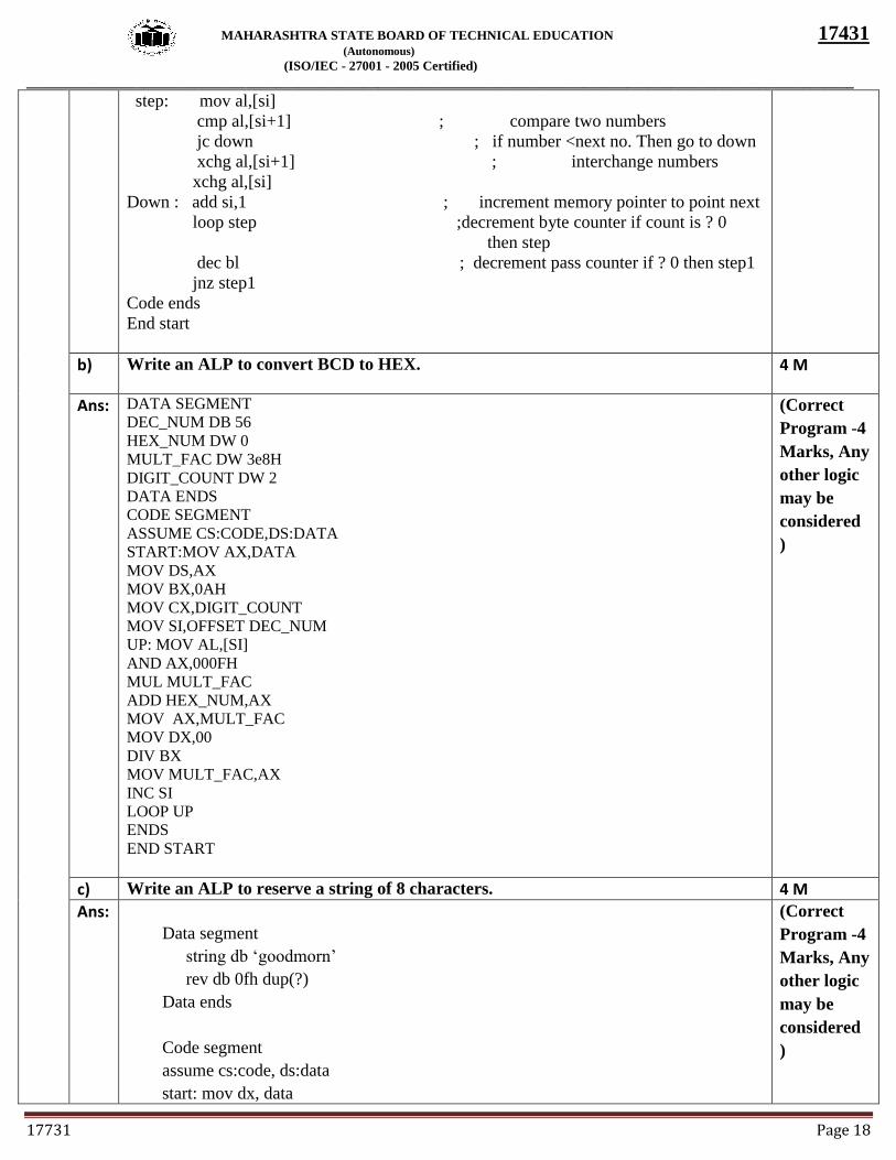
step: mov al,[si]
cmp al,[si+1] ; compare two numbers
jc down ; if number <next no. Then go to down
xchg al,[si+1] ; interchange numbers
xchg al,[si]
Down : add si,1 ; increment memory pointer to point next
loop step ;decrement byte counter if count is ? 0
then step
dec bl ; decrement pass counter if ? 0 then step1
jnz step1
Code ends
End start
b) Write an ALP to convert BCD to HEX.
4 M
Ans: DATA SEGMENT
DEC_NUM DB 56
HEX_NUM DW 0
MULT_FAC DW 3e8H
DIGIT_COUNT DW 2
DATA ENDS
CODE SEGMENT
ASSUME CS:CODE,DS:DATA
START:MOV AX,DATA
MOV DS,AX
MOV BX,0AH
MOV CX,DIGIT_COUNT
MOV SI,OFFSET DEC_NUM
UP: MOV AL,[SI]
AND AX,000FH
MUL MULT_FAC
ADD HEX_NUM,AX
MOV AX,MULT_FAC
MOV DX,00
DIV BX
MOV MULT_FAC,AX
INC SI
LOOP UP
ENDS
END START
(Correct
Program -4
Marks, Any
other logic
may be
considered
)
c) Write an ALP to reserve a string of 8 characters. 4 M
Ans:
Data segment
string db ‘goodmorn’
rev db 0fh dup(?)
Data ends
Code segment
assume cs:code, ds:data
start: mov dx, data
(Correct
Program -4
Marks, Any
other logic
may be
considered
)
Page 19
MAHARASHTRA STATE BOARD OF TECHNICAL EDUCATION 17431
(Autonomous)
(ISO/IEC - 27001 - 2005 Certified)
_________________________________________________________________________________________________________________
17731 Page 19
mov ds,dx
lea si, string
mov cx,0fh
lea di, rev
add di,0fh
up: mov al, [si]
mov [di], al
Inc si
dec di
loop up
code ends
end start
d) State the function of following instruction of 8086
i. STC
ii. CMC
iii. CLD
iv. STI
4 M
Ans: i) STC : This instruction indicates the set CARRY FLAG.
CF=1
ii) CMC: It will complement the carry flag.
CF=~CF
iii) CLD : In this instruction is indicating the clear DIRECTION FLAG
DF= 0
iv) STI :STI the instruction indicates the set INTERRUPT FLAG.
IF = 1
(Each instruction function :1
Mark )
e) What is meant by macro’s? Describe their uses.
4 M
Ans: Macro
Small sequence of the codes of the same pattern are repeated frequently at different places
which perform the same operation on the different data of same data type, such repeated
code can be written separately called as Macro.
Macro is also called as open subroutine.
(OR)
Macro definition or (Macro directive):
Syntax:
Macro _name MACRO[arg1,arg2,…..argN)
…..
ENDM
Uses of Macro:
Macros are used to :-
1. Simplify and reduce the amount of repetitive coding.
2. Reduces errors caused by repetitive coding.
(Correct
Definition:
2 Marks,
Any 2 uses:
1 Mark
each)
Page 20
MAHARASHTRA STATE BOARD OF TECHNICAL EDUCATION 17431
(Autonomous)
(ISO/IEC - 27001 - 2005 Certified)
_________________________________________________________________________________________________________________
17731 Page 20
3. Make program more readable.
4. Reduce the Execution time as compare to procedure as no extra instructions are
required.
f) What is procedure? What are the two advantages of using procedure in our
program.
4 M
Ans: 1) Procedure is a series of instructions is to be executed several times in a program,
and called whenever required.
2) Program control is transferred to the procedure, when CALL instruction is
executed at run time.
3) Memory required is less, as the program control is transferred to procedure.
4) Stack is required at Procedure CALL.
5) Extra overhead time is required for linkage between the calling program and
called procedure.
6) Parameters passed in registers, memory locations or stack.
7) RET is required at the end of the Procedure.
8) Procedure is called using:
CALL <Procedure_name>
9) Directives used: PROC, ENDP, FAR,NEAR
General Form :
Procedure Name PROC
-------------------------------------
Procedure Statements
-------------------------------------
Procedure Name ENDP.
Advantages:
1) Modular programming
2) Reduced to work load and development time
3) Debugging of program easier
4) Reduction of line of code
5) Reusability of code
6) Library of procedure can be implemented.
(Correct
Description
: 2 Mark,
Any 2
Advantages
:1 Mark
each)
Q.6 Attempt any TWO of following: 16 M
a) Draw the functional block diagram of 8086 microprocessor and describe instruction
queue in detail.
8 M
Ans: To implement any instruction first it is to be fetched, then decoded and then executed.
The fetching of an instruction involves its address to be sent out to the system memory
and then the memory sending back the instruction.
While the EU is busy decoding or executing certain instructions which do not need
the buses, the BIU fetches next six instruction bytes and stores them in a first-in-first-out
(FIFO) register set called queue.
The processor doesn't have to wait for the next instruction to be fetched as it is
(Block diagram :4 Marks, Description of instruction queue :4 Marks)
Page 21
MAHARASHTRA STATE BOARD OF TECHNICAL EDUCATION 17431
(Autonomous)
(ISO/IEC - 27001 - 2005 Certified)
_________________________________________________________________________________________________________________
17731 Page 21
already made available in the queue registers. Thus, the speed of operation is enhanced.
This prefetching of next instruction while another instruction is still being executed is
known as pipelining.
b) Write an ALP to count odd numbers in an array of five 8 bit numbers.
8 M
Ans: DATA SEGMENT
ARRAY DB 02H,05H,06H,07H,03H
ODD DB 00H
DATA ENDS
CODE SEGMENT
START:ASSUME CS:CODE,DS:DATA
MOV DX,DATA
MOV DS,DX
MOV CL,05H
MOV SI,OFFSET ARRAY
NEXT:MOV AL,[SI]
ROR AL,1 ;or RCR
JNC DN ; Check for Odd
INC ODD
DN : INC SI
LOOP NEXT
MOV AH,4CH
INT 21H
CODE ENDS
END START
(Correct
Program -8
Marks,
Any other
logic may
be
considered)
Page 22
MAHARASHTRA STATE BOARD OF TECHNICAL EDUCATION 17431
(Autonomous)
(ISO/IEC - 27001 - 2005 Certified)
_________________________________________________________________________________________________________________
17731 Page 22
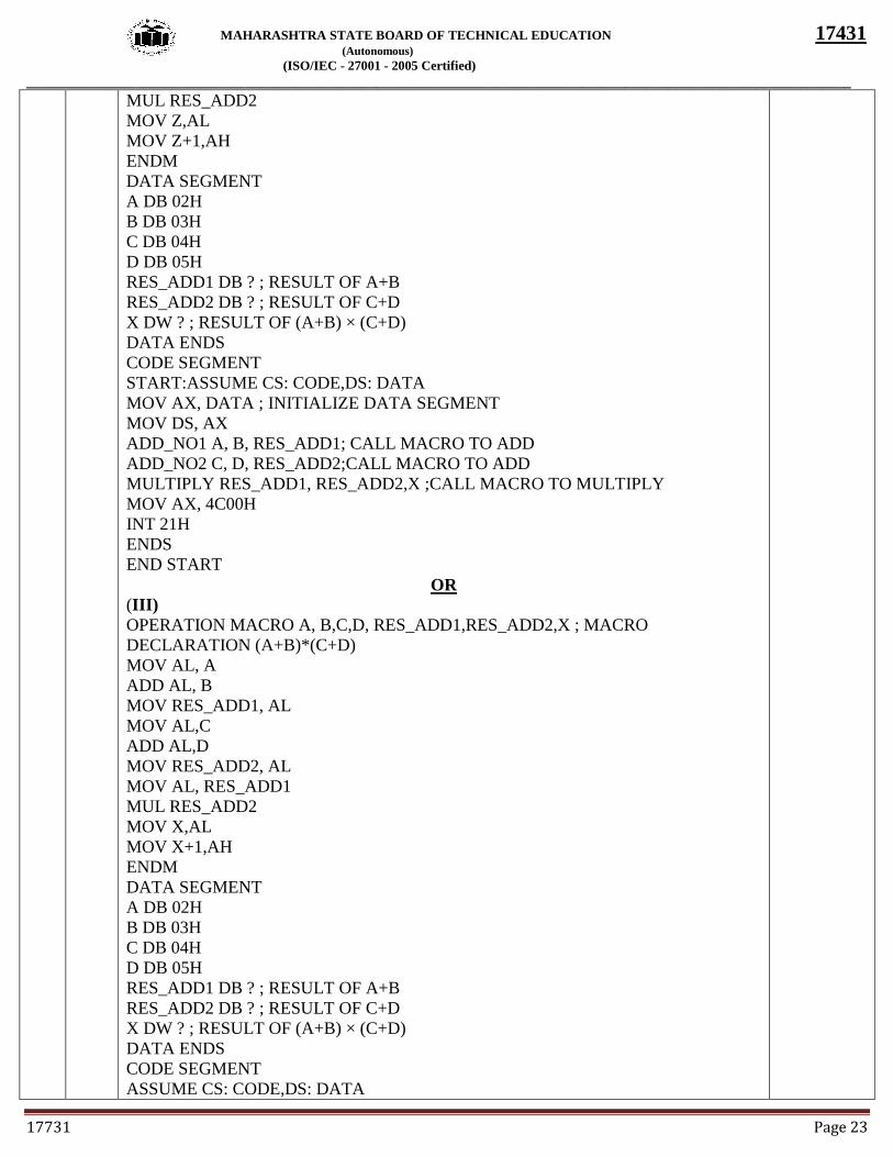
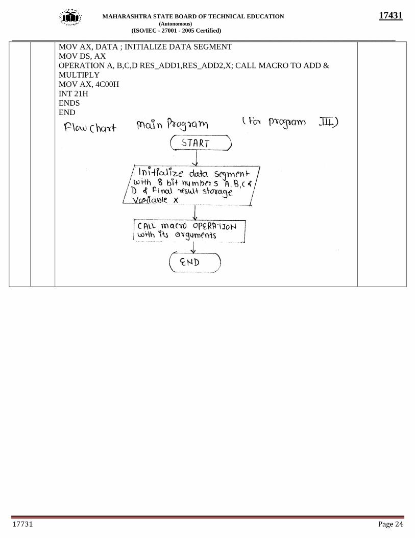
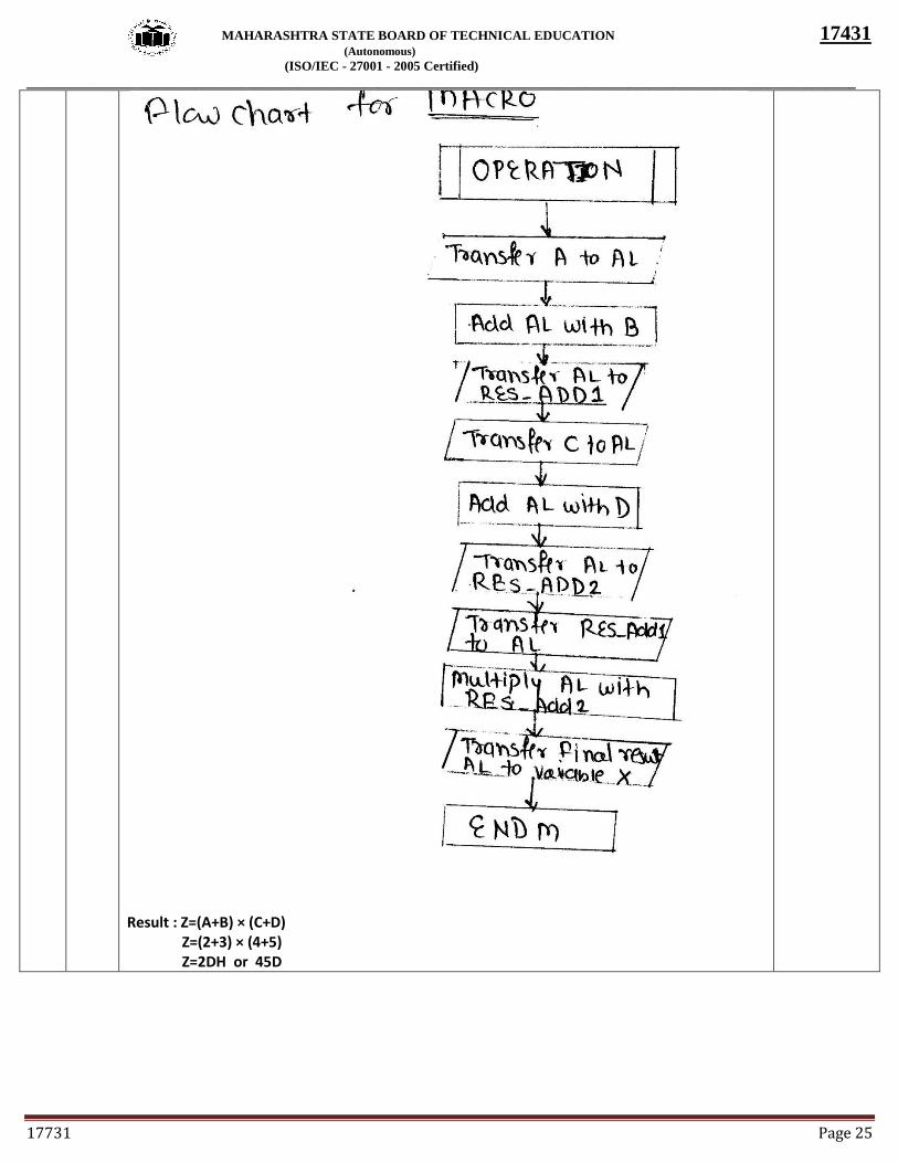
c) Write an ALP using procedure for performing the operation Z= ( A +B) * (C +D)
A,B,C,D, are of 8 bit number. Draw flowchart and write result.
8 M
Ans: DATA SEGMENT
A DB 02H
B DB 03H
C DB 04H
D DB 05H
Z DW ?
DATA ENDS
CODE SEGMENT
ASSUME CS:CODE, DS: DATA
MOV AX, DATA
MOV DS, AX
CALL FIND_RES
FIND_RES PROC NEAR
PUSHF
PUSH AX
PUSH BX
MOV AL, A
ADD AL, B
MOV BL, C
ADD BL, D
MUL BL
MOV Z, AX
POP BX
POP AX
POPF
RET
FIND_RES ENDP
MOV AX,4C00H
INT 21H
CODE ENDS
END START
OR
II )
ADD_NO1 MACRO A, B, RES_ADD1 ; MACRO DECLARATION (A+B)
MOV AL, A
ADD AL, B
MOV RES_ADD1, AL
ENDM
ADD_NO2 MACRO C, D, RES_ADD2 ; MACRO DECLARATION (C+D)
MOV AL, C
ADD AL, D
MOV RES_ADD1, AL
ENDM
MULTIPLY MACRO RES_ADD1, RES_ADD2,X; MACRO DECLARATION
X=(A+B)*(C+D)
MOV AL, RES_ADD1
(Correct
Program -4
Marks,
Any other
logic may
be
considered,
flowchart 3
Marks,
Result : 1
Mark )
Page 23
MAHARASHTRA STATE BOARD OF TECHNICAL EDUCATION 17431
(Autonomous)
(ISO/IEC - 27001 - 2005 Certified)
_________________________________________________________________________________________________________________
17731 Page 23
MUL RES_ADD2
MOV Z,AL
MOV Z+1,AH
ENDM
DATA SEGMENT
A DB 02H
B DB 03H
C DB 04H
D DB 05H
RES_ADD1 DB ? ; RESULT OF A+B
RES_ADD2 DB ? ; RESULT OF C+D
X DW ? ; RESULT OF (A+B) × (C+D)
DATA ENDS
CODE SEGMENT
START:ASSUME CS: CODE,DS: DATA
MOV AX, DATA ; INITIALIZE DATA SEGMENT
MOV DS, AX
ADD_NO1 A, B, RES_ADD1; CALL MACRO TO ADD
ADD_NO2 C, D, RES_ADD2;CALL MACRO TO ADD
MULTIPLY RES_ADD1, RES_ADD2,X ;CALL MACRO TO MULTIPLY
MOV AX, 4C00H
INT 21H
ENDS
END START
OR
(III)
OPERATION MACRO A, B,C,D, RES_ADD1,RES_ADD2,X ; MACRO
DECLARATION (A+B)*(C+D)
MOV AL, A
ADD AL, B
MOV RES_ADD1, AL
MOV AL,C
ADD AL,D
MOV RES_ADD2, AL
MOV AL, RES_ADD1
MUL RES_ADD2
MOV X,AL
MOV X+1,AH
ENDM
DATA SEGMENT
A DB 02H
B DB 03H
C DB 04H
D DB 05H
RES_ADD1 DB ? ; RESULT OF A+B
RES_ADD2 DB ? ; RESULT OF C+D
X DW ? ; RESULT OF (A+B) × (C+D)
DATA ENDS
CODE SEGMENT
ASSUME CS: CODE,DS: DATA
Page 24
MAHARASHTRA STATE BOARD OF TECHNICAL EDUCATION 17431
(Autonomous)
(ISO/IEC - 27001 - 2005 Certified)
_________________________________________________________________________________________________________________
17731 Page 24
MOV AX, DATA ; INITIALIZE DATA SEGMENT
MOV DS, AX
OPERATION A, B,C,D RES_ADD1,RES_ADD2,X; CALL MACRO TO ADD &
MULTIPLY
MOV AX, 4C00H
INT 21H
ENDS
END
Page 25
MAHARASHTRA STATE BOARD OF TECHNICAL EDUCATION 17431
(Autonomous)
(ISO/IEC - 27001 - 2005 Certified)
_________________________________________________________________________________________________________________
17731 Page 25
Result : Z=(A+B) × (C+D) Z=(2+3) × (4+5) Z=2DH or 45D