MAIN BIRD EXCREMENT CONTAMINATION TYPE CAUSING INSULATOR FLASHOVERS IN 110 kV OVERHEAD POWER LINES IN ESTONIA
PAUL TAKLAJA*, REIN OIDRAM, JAAN NIITSOO, IVO PALU Department of Electrical Power Engineering Tallinn University of Technology Ehitajate tee 5, 19086 Tallinn, Estonia
Abstract. The study aims to elucidate which type of bird excrement contamination causes insulator flashovers in 110 kV overhead power lines in Estonia. Laboratory wetting and bird streamer tests performed on naturally contaminated glass and composite insulators show that most likely the flashovers are caused by highly conductive bird excrement streamers and that insulator properties have little influence, if any, on the generation of this kind of contamination driven flashovers. Keywords: glass insulators, composite insulators, naturally polluted insulators, wetting tests, bird streamer tests, corona rings, leakage currents, partial discharges, flashovers.
1. Introduction
The transmission system operator (TSO) of Estonian electrical power grid, Elering AS, has encountered a problem with indefinite faults in the grid (flashovers on overhead line insulators). As the number of such faults has increased in the last years, TSO started to seek actively the cause of faults in order to eliminate the problem and maintain the high reliability of the power grid. To this effect, TSO collected data about indefinite faults from 2005 to 2009 and started, in cooperation with Tallinn University of Technology, to analyze in more detail their possible causes.
The root cause of indefinite faults was identified in a preliminary study “Causes of indefinite faults in Estonian 110 kV overhead power grid” [1]. This research concluded that indefinite faults are mostly caused by excrements of large birds. In Estonia, these birds are presumably white storks.
The present study strives to find out which of the two bird excrement contamination types, traditional, i.e. natural insulator surface contamination (type a), or transient, i.e. the highly conductive bird streamer contamination short circuiting the traverse and phase conductor (type b) [2], mostly leads to insulator flashover. Also, it attempts to establish whether there is any difference in bird excrement contamination withstanding between glass and composite insulators, to have better operation reliability, i.e. decrease the number of flashovers. The insulators tested are characterized in Table 1 and illustrated in Figure 1. Figures 2–12 depict naturally contaminated and retired insulators with different types of contamination, partial discharges, dry band arching, corona rings, leakage currents, loss of hydrophobicity and erosion of end fittings examined in this paper.
2. Insulators tested
Table 1. Insulators tested
Manufacturer specifications Manufacturer ISOELECTRIC LAPP Type ПС-70Е ПС-70Е ISI-ROK RODURFLEX Material Glass Glass Composite Composite Number of insulators 1 8 1 1 Number of sheds 1 8 12 + 11 13 Shed diameter, mm 255 255 145 + 110 130 Corona ring diameter, mm – – 205 351 Selection length, mm 127 1 016 1160 1168 Creepage distance, mm 303 2424 3050 2388 Arcing distance, mm 250 1140 850 991 50 Hz flashover voltage, dry, kV 70 485 340 380 50 Hz flashover voltage, wet, kV 40 335 265 340 1.2/50 impulse voltage, pos., kV 100 670 570 620 1.2/50 impulse voltage, neg., kV 100 695 615 635 Weight, kg 3.4 27.2 5.4 4.1
Fig. 1. Insulators tested: a – ПС-70Е; b – ISOELECTRIC; c – LAPP.
a b c
Main Bird Excrement Contamination Type Causing Insulator Flashovers ...
213
3. Visual inspection of insulators
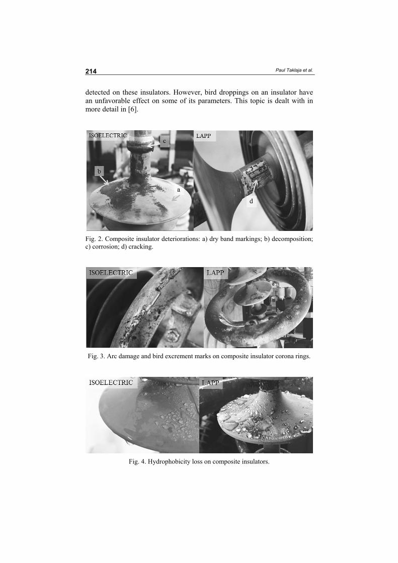
Based on visual inspection it can be said that regardless of type, all naturally contaminated insulators have easily noticeable deteriorations. Brighter shed surface zones (discoloration and dry band markings [3]), darker coating surface zones (decomposition of silicone rubber under the influence of arc temperature [4]), corrosion of end fittings, corrosion of traverse and/or insulator conductor clamps spreading to end fittings and sheds, decreased hydrophobicity of shed surfaces (deteriorations at insulator line end sheds, shed rims and shafts tend to be more severe because these areas have lost most of their hydrophobic properties), contamination by volatile air particles and bird excrement imprints were sighted on the composite insulators inspected (Figs. 2–4). These insulators had been in use for approximately three years before retirement.
Presumably, many of the illustrated (Figs. 2–4) vast deteriorations (but predominantly darker coating surface zones) of some composite insulators are produced by long-lasting high temperature flashover arcs. These long-lasting short-circuit arcs in the power grid are mainly caused by the maloperation of the line protection equipment. Maloperation of the protec-tion equipment usually produces longer interruptions and the high heat of the arc can thermally injure the insulators.
However, flashovers are most probably caused by bird streamers since only traces of droppings could be observed on the vastly deteriorated insulators. Usually, the droppings were concentrated on top of the first-end shed of the insulator.
The presumption that flashovers are driven by bird streamers are backed up by the facts that those relatively clean, but thermally injured composite insulators had also severe melting marks on corona rings and end fittings. This indicates that something was short-circuiting corona rings and end fittings and flashovers were not driven by traditional pollution accumulation.
The composite insulators with some bird excrement contamination and no severe melting marks on corona rings were less deteriorated. There were substantially fewer dark coating surface zones, but dry band markings, decoloration and loss of hydrophobicity (more stresses were near the droppings marks) were still detected. Although the insulators had been in operation for only approximately three years, there was a noticeable layer of dust particles on composite insulators, which had been absorbed by the diffusion and embedding effect of the silicon coating [5]. The inspected LAPP insulators were less deteriorated and their hydrophobicity was better than that of ISOELECTRIC insulators.
Based on the visual inspection of composite insulators it can be con-cluded that flashovers are most probably caused by bird streamers short-circuiting the traverse and phase conductor, not by the bird excrement contamination deposition on the insulator surfaces, since only small amounts of droppings, which were usually concentrated in few separate spots, were
Paul Taklaja et al.
214
detected on these insulators. However, bird droppings on an insulator have an unfavorable effect on some of its parameters. This topic is dealt with in more detail in [6].
Fig. 2. Composite insulator deteriorations: a) dry band markings; b) decomposition; c) corrosion; d) cracking.
Fig. 3. Arc damage and bird excrement marks on composite insulator corona rings.
Fig. 4. Hydrophobicity loss on composite insulators.
Main Bird Excrement Contamination Type Causing Insulator Flashovers ...
215
The inspected glass insulators were by far more contaminated by bird excrements. On the basis of visual observation no assumption was made about which type of contamination, bird excrement deposition or streamer, was a major cause of flashovers. The viewed glass insulator strings had been in operation for decades before retirement. The droppings induced cap corrosion was also noticed (Fig. 5). Considerable amounts of corroded traverse and/or conductor suspension clamps remnants were spread on insulators.
Fig. 5. Severe bird excrement contamination on a glass insulator disk. Cap corrosion.
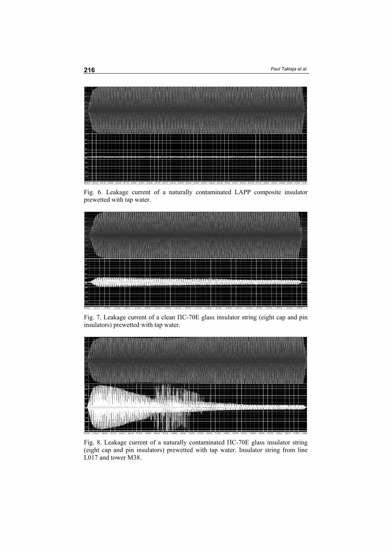
4. Leakage currents of dry and wetted insulators at steady state phase to ground voltages
Different types of naturally contaminated insulators were tested at the highest steady state voltages for equipment to determine whether flashovers of wetted insulators are possible. In Figures 6 to 8 leakage currents of different wetted insulators are shown. In the oscillograms the voltages (upper, grey) and currents (lower, white) have the following relative units: for voltage 1 = 101 kV and for current 1 = 10 mA. 101 kV (1) is the highest phase to ground amplitude voltage for equipment in the 110 kV AC power grid. In the 110 kV power grid the highest phase to phase voltage for equipment is 123 kV [7]. One test lasted about 10 minutes:
123 2 101 (kV)3
⋅ ≈ (1)
The leakage currents of dry and wetted naturally contaminated composite insulators were smaller than the sensitivity of the transformer cascade measuring device, i.e. less than 0.5 mA (Fig. 6).
The leakage current of a dry clean ПС-70Е insulator string (eight standard glass cap and pin insulators) was ca 1 mA. The highest leakage current of the clean glass insulator string wetted by rainwater was about 1.5 mA, and of that
Paul Taklaja et al.
216
Fig. 6. Leakage current of a naturally contaminated LAPP composite insulator prewetted with tap water.
Fig. 7. Leakage current of a clean ПС-70Е glass insulator string (eight cap and pin insulators) prewetted with tap water.
Fig. 8. Leakage current of a naturally contaminated ПС-70Е glass insulator string (eight cap and pin insulators) prewetted with tap water. Insulator string from line L017 and tower M38.
Main Bird Excrement Contamination Type Causing Insulator Flashovers ...
217
wetted with tap water about 2.0 mA (Fig. 7). The highest leakage current of the wetted naturally contaminated glass insulator string was approximately 9.5 mA (Fig. 8).
5. Registration of partial discharges and flashovers on insulators
No flashovers were recorded during the tests with insulators. Water droplets and dried surface zones with declined hydrophobicity caused partial discharges and dry band arching on composite insulators but the intensity and extent of dry band arching were low. The intensity of partial discharges was higher on naturally contaminated ISOELECTRIC composite insulators than on naturally contaminated LAPP insulators. It may be related to the fact that the hydrophobicity of LAPP insulators is preserved better and that the diffusion of the wetted contamination through the protective polymer layer takes more than 20 minutes, which was the approximate time of one test.
The role of the corona ring in reducing partial discharges is substantial. No visible partial discharges were detected on LAPP insulators when the corona ring was attached to the line end of an insulator (Fig. 9). The intensity of partial discharges on ISOELECTRIC insulators decreased when corona rings were used. However, there could still be detected a considerable number of partial discharges on the insulators (Fig. 10).
As seen from Figures 6 and 8, composite insulators withstand contamina-tion better than glass insulator strings in terms of wet resistance and leakage currents. Differences in leakage currents between the wetted contaminated insulators are remarkable. So, the leakage currents of composite insulators are lower than those of glass insulators, meaning that electrical power losses on composite insulators are also smaller than on glass insulators. Differences in dissipated power between the insulators are so great that when a composite insulator needs the sun and wind to dry, then a glass insulator dries mainly due to dissipated power. This finding is also supported by the results reported in [5].
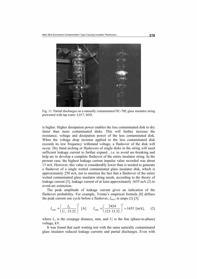
A very intensive and extensive dry band arching and a flashover of a single disk in the string in one case (Fig. 11) were detected on prewetted naturally contaminated glass insulators. Leakage current change of a prewetted con-taminated glass insulator in timeline is seen in Figure 8. At first, when the phase voltage is applied to the insulator, as seen in Figure 8, its leakage current begins to decrease. After decreasing it will start to increase again at some point, thereafter decreasing again. This temporal increase of the leakage current of a drying insulator string is caused by partial discharges, dry band arching and flashovers of single disks in the string that are partly short-circuiting the creepage distance of the string, thereby increasing its leakage current. However, the rate of leakage current increase was too low to cause dry band arching to develop the arching of the entire string. This means that the total remaining conductivity of the non-short circuited path of the insulator creepage distance was not high enough to feed the arc to induce a flashover.
Paul Taklaja et al.
218
Fig. 9. Partial discharges on a naturally contaminated LAPP composite insulator prewetted with tap water: a) without a corona ring, b) with a corona ring.
Fig. 10. Partial discharges on a naturally contaminated ISOELECTRIC composite insulator prewetted with tap water: a) without a corona ring, b) with a corona ring.
It is important to note that a more intensive dry band arching and in one
case a flashover of a single disk in the string was observed just on the cleanest disks in the prewetted naturally contaminated insulator string (Fig. 11). This can be explained by the fact that the surface resistance of the contaminated insulator disk is lower than that of the clean disk. The difference in resistance between the disks affects the voltage dividing between them in the string. The highest voltage drop is applied to the insulator whose resistance is the highest. The higher voltage drop at the same current means that the dissipation power
Main Bird Excrement Contamination Type Causing Insulator Flashovers ...
219
Fig. 11. Partial discharges on a naturally contaminated ПС-70Е glass insulator string prewetted with tap water: L017, M38.
is higher. Higher dissipation power enables the less contaminated disk to dry faster than more contaminated disks. This will further increase the resistance, voltage and dissipation power of the less contaminated disk. When the voltage drop increase applied to the less contaminated disk exceeds its low frequency withstand voltage, a flashover of the disk will occur. Dry band arching or flashovers of single disks in the string will need sufficient leakage current to further expand , i.e. to avoid arc-breaking and help arc to develop a complete flashover of the entire insulator string. In the present case, the highest leakage current impulse value recorded was about 13 mA. However, this value is considerably lower than is needed to generate a flashover of a single wetted contaminated glass insulator disk, which is approximately 250 mA, not to mention the fact that a flashover of the entire wetted contaminated glass insulator string needs, according to the theory of leakage current [3], leakage current of at least approximately 1655 mA (2) to avoid arc extinction.
The peak amplitude of leakage current gives an indication of the flashover probability. For example, Verma’s empirical formula [8] defines the peak current one cycle before a flashover, Imax, in amps (2) [3]:
2 2
max max2424[A] 1655 [mA],
15.32 123 15.32s
l
LI IU = = ≈ ⋅ ⋅
(2)
where Ls is the creepage distance, mm, and Ul is the line (phase-to-phase) voltage, kV.
It was found that each wetting test with the same naturally contaminated glass insulator reduced leakage currents and partial discharges. Even with
Paul Taklaja et al.
220
slight wetting, there was no significant fall of droplets from the insulator and its surface was dried by the leakage current and partial discharges. The cleaning (i.e. leakage current reducing) effect of sprayed water was significant. This means that even a light rainfall may considerably reduce leakage currents caused by the wetted (excrement) contamination on the insulator surface. It may be concluded that condensed water (fog, dew) probably increases the values of leakage current on the contaminated insulator more than rainfall whose cleaning ability is good.
6. Insulator resistance measurement
The resistance of insulators was measured using a high-sensitivity ohm-meter. The obtained values show that in terms of wet resistance and leakage currents, composite insulators withstand contamination better than glass insulators. The resistance values of wetted naturally contaminated composite insulators are by several orders of magnitude higher than those of glass insulator strings (Table 2).
Table 2. Resistance of naturally contaminated insulators wetted by rainwater
Insulator Rdry, Ω, Rwet, Ω Comments
LAPP L178, M5 (1) >10·1012 >10·1012 Severely damaged by arc LAPP L178, M5 (2) >10·1012 60·1011 Damaged by arc LAPP L178, M4 >10·1012 30·1011 Corrosion on upper end fitting and sheds ISOELECTRIC 03 >10·1012 70·1011 Corrosion on end fittings ISOELECTRIC 01 >10·1012 30·1011 Corrosion on upper end fitting and sheds ISOELECTRIC 02 15·1011 40·1010 Corrosion on ground end fitting Insulator string 50·1011 66·1008 Clean, no contamination Insulator string L131B 40·1011 22·1006 Corrosion imprints on upper insulators Insulator string L017, M38 30·1011 15·1006 Severely contaminated by bird excrements
The wet resistance of the disks of glass insulator strings was also
measured (Table 3). Calculated voltage dividing among the disks was done using measured wet resistance values; capacitive components were not taken into account. Nevertheless, the calculated data compare well with the rate of the partial discharges illustrated in Figure 11. It may be noticed that partial discharges (Fig. 11) occur more frequently on insulator disks whose resistance is higher, i.e. are cleaner, and whose voltage drops are more significant (Table 3). Insulator disk 5, whose resistance was the highest (Table 3), also suffered a flashover (Fig. 11) during the test.
Main Bird Excrement Contamination Type Causing Insulator Flashovers ...
221
Table 3. Measured disk resistance values and calculated voltage dividing
Insulator string L017, M38
Ins, no R, MΩ V, kV
8 1.1 5.3
7 2.2 10.7
6 2.8 13.6
5 3.4 16.5
4 1.2 5.8
3 2.4 11.7
2 1.0 4.9
1 0.5 2.4
7. Bird streamer discharge imitating test
Consisting in short-circuiting with a conductive liquid jet, the laboratory simulation of streamer discharge between the traverse and the phase con-ductor as well as the traverse and the insulator corona ring was successful (Fig. 12). The sprayer was used as a ‘bird’; the sprayer nozzle diameter was 8 mm, the resistance of the saltwater stream about 20 kΩ/m [2] and the phase to ground voltage level was 71 kV (rms.). During the tests it appeared that when the water stream was free-falling from the nozzle (the water system pressure was minimal), the maximal length between the nozzle and the phase conductor to have a successful streamer discharge is approximately 0.6 m. The continuity of the water stream becomes important if one would like to have a streamer discharge longer than 0.6 m. A longer stream will be frag-mented and the stream head will scatter and therefore no streamer discharge will occur. The continuity of the stream is affected by nozzle diameter, viscosity and flow of the liquid, electrical field, air resistance and gravitation. Since changing and measuring water viscosity was troublesome in laboratory conditions, the pressure of the water spray system was increased, i.e. the water flow rate was increased to have longer streamer discharges. With higher water spray system pressures there were no problems to achieve streamer discharges longer than 0.6 m. The minimal volume of the highly conductive saltwater to have a 1 m streamer discharge was approximately 80 ml.
It can be concluded that streamer discharge needs a number of matching factors to occur and this is by no means a process to take place easily. Bird excrement streamer must be of sufficiently high conductivity, with large diameter, high viscosity, speed and volume, and has to pass the phase conductor or/and corona ring as closely as possible. It is difficult to present any detailed parameters about bird excrements because these were not the subject of this study and no pertinent literature was found either.
Paul Taklaja et al.
222
Fig. 12. Highly conductive saltwater stream induced flashovers: a) between the nozzle mouth and phase conductor; b) between the nozzle mouth and composite insulator corona ring.
To investigate the effect of insulator corona rings on the bird streamer
discharge, unknowing the exact parameters of bird streamers, the worst-case scenario was used. It means that the discharge distance h from the phase conductor and corona ring was determined by the grounded metal wire rod which was positioned crosswise with respect to the phase conductor and parallel with respect to the insulator. At the phase voltage of 71 kV and at normal temperature and pressure this distance was about 17 cm. The negative effect of corona rings is depicted in Figure 13 (c and b vs a). This means that the area of possible bird streamer caused flashovers is increased when birds excrete dropping streams on the traverse above vertically positioned insulators. The high-risk flashover area is seen between two thin black lines in Figure 13, e.
The above is indicative of the inconsistency of using corona rings at the composite insulator line end. Using corona rings decreases partial discharges on wetted insulators, thereby increasing their life-span. Corona rings also increase the risk of bird streamer flashovers and the flashover-produced high-temperature arc may damage composite insulator surfaces. However, partial discharges on wetted insulators without corona rings will decrease their life-span, but the probability of bird streamer flashovers will also decrease.
Main Bird Excrement Contamination Type Causing Insulator Flashovers ...
223
Fig. 13. Insulators with different diameters, effect of corona ring, grounded metal rod discharge distance h to the phase conductor or corona ring at 71 kV (rms) phase to ground voltage (vertically positioned suspension insulators, top view): a) insulator ПС-70Е, ø 255 mm; b) insulator ISOELECTRIC, ø 145 mm, with a corona ring, ø 205 mm; c) insulator LAPP, ø 130 mm, with a corona ring, ø 351 mm; d) corona rings; e) grounded metal rod discharge distance h to the phase conductor or corona ring; f) phase conductor.
Composite insulator manufacturers recommend to use corona rings at
the insulator line end, starting from the phase to phase voltage for ISOELECTRIC Ul ≥ 200 kV and for LAPP Ul ≥ 230 kV. The minimum diameter of available ISOELECTRIC corona rings is 20.5 cm and of LAPP, 35.1 cm [9, 10]. Given the manufacturers’ predictions about insulator life-span, it is advisable not to use corona rings at a 123 kV phase to phase voltage to decrease the risk of bird streamer flashovers. However, being more cautious about these predictions, it is advisable to use corona rings at the insulator line end to decrease the rate of partial discharges, and apply other measures to decrease the risk of bird streamer flashovers on the insulators.
The most significant parameter to reduce the possibility of bird streamer flashovers on vertically positioned suspension insulators is insulator dia-meter (Fig. 13). The possibility of a bird streamer flashover decreases with larger insulator diameter. A larger diameter insulator diminishes the high-risk area of possible bird streamer flashovers (compare diameters of insulators c and a shown in gray in Fig. 13). Insulator diameter must be large enough to prevent the bird streamer from short-circuiting the traverse and phase conductor. Replacing insulators with smaller diameter by larger diameter ones may be challenging. However, in practice this is difficult to implement as insulators with sufficiently large diameters are not manu-factured. Moreover, larger insulator diameter would also favour the deposi-tion of droppings on insulators, which may deteriorate their properties. Instead, special insulator covers should be used.
Paul Taklaja et al.
224
Conclusions
In conclusion, based on the results of laboratory tests it may be said that the main type of bird excrement contamination that leads to insulator flashovers in 110 kV overhead power lines in Estonia is most probably bird streamer contamination and not deposited bird excrement contamination. This means that changing insulator types or properties gives little effect, if any, on reducing flashovers caused by bird excrement contamination.
Acknowledgment
The authors are very grateful to Elering AS for financial support and supply of initial data. Väino Milt, expert on HV power lines at Elering AS, is specifically thanked for pleasant cooperation. REFERENCES
1. Taklaja, P., Oidram, R., Niitsoo, J., Palu, I. Causes of indefinite faults in Estonian 110 kV overhead power grid. Oil Shale, 2013, 30(2S), 225–243.
2. IEC, Standard 60815-1 “Selection and dimensioning of high-voltage insulators intended for use in polluted conditions – Part 1: Definitions, information and general principles”, 2008.
3. CIGRE, Guide for the establishment of naturally polluted insulator testing stations, 2007.
4. Mazurek, B., Maczka, T., Gmitrzak, A. Effect of arc current on properties of composite insulators for overhead line. Proceedings of the 6th International Conference on Properties and Applications of Dielectric Materials, June 21–26, Xi’an Jiotang University, Xi'an, China, 2000, 2, 802–805.
5. Grigsby, L. L (ed.). The Electric Power Engineering Handbook. IEEE Press, CRC Press LLC, 2001.
6. Looms, J. S. T. Insulators for High Voltages. Peter Peregginus Ltd., London, United Kingdom, 1988.
7. IEC, Standard 60071-1 “Insulation co-ordination – Part 1: Definitions, principles and rules”, 2006.
8. Verma, M. P., Heise, W., Liphen, H., Luxa, G. F., Schreiber, H. The criterion for the pollution flashover and its application to insulation dimensioning and control. CIGRE report 33-09, 1978.
9. LAPP, Rodurflex Composite Insulators Catalog. LeRoy, New York, 2006. 10. ISOELECTRIC, Composite Silicone Insulators Catalog, 2009. Received October 10, 2012