16
MAIN CATALOG SUPPLEMENT 2018 | INCH
MAIN CATALOG SUPPLEMENT 2018 | INCH

MAIN CATALOG SUPPLEMENT
A d v a n c e d T h r e a d i n g S o l u t i o n s
THREAD MILLINGTM Solid TMDRDrilling, Thread Milling & Chamfering ...........................3
TM Solid HCNFor Long Threads (3xDo) .......................................................9
THREAD TURNINGD-LineDeep Rake Internal Inserts ................................................ 12
2
Thread Milling
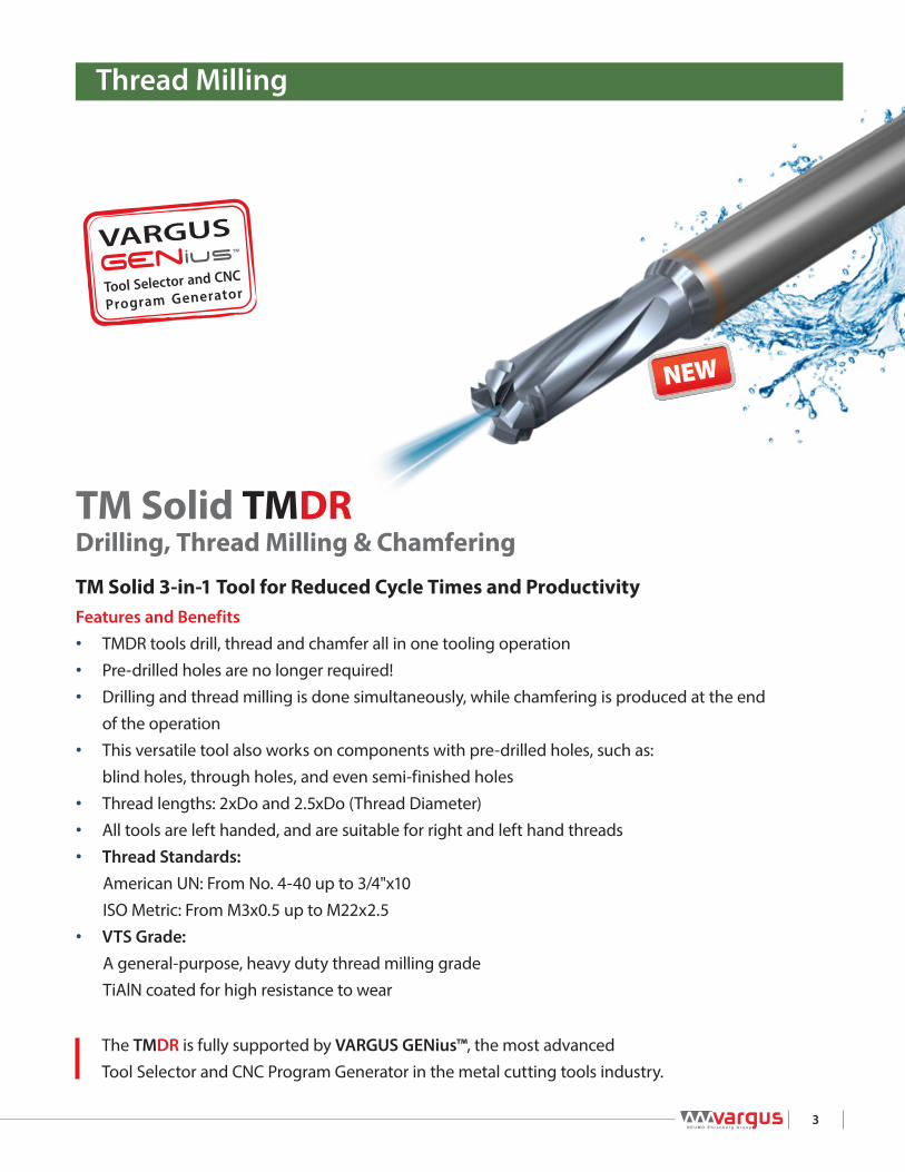
TM Solid 3-in-1 Tool for Reduced Cycle Times and ProductivityFeatures and Benefits• TMDR tools drill, thread and chamfer all in one tooling operation• Pre-drilled holes are no longer required!• Drilling and thread milling is done simultaneously, while chamfering is produced at the end
of the operation• This versatile tool also works on components with pre-drilled holes, such as:
blind holes, through holes, and even semi-finished holes• Thread lengths: 2xDo and 2.5xDo (Thread Diameter)• All tools are left handed, and are suitable for right and left hand threads• Thread Standards:
American UN: From No. 4-40 up to 3/4"x10 ISO Metric: From M3x0.5 up to M22x2.5
• VTS Grade:A general-purpose, heavy duty thread milling gradeTiAlN coated for high resistance to wear
The TMDR is fully supported by VARGUS GENius™, the most advanced Tool Selector and CNC Program Generator in the metal cutting tools industry.
Drilling, Thread Milling & ChamferingTM Solid TMDR
3

* Coolant available only when specified
TMDR - Drilling, Thread Milling & Chamfering 2.5 x Do (L1 ≤ 2.5 x Thread Diameter)
Thread Pitch Ordering Code EDP No. Dimensions Inch No. of Flutes Teeth
UNC UNF UN TPI Internal VTS D D2 L L1 Z Zt L4 D1
Without coolantNo.4-40, No.5-40 No.6-40 40 TD-2L25083L346-I40UNC… 81131 1/4 .083 2.283 .346 3 2 .015 .069No.6-32, No.8-32 32 TD-2L25102L413-I32UNC… 81133 1/4 .102 2.283 .413 3 2 .018 .087No.8-32 No.10-32 32 TD-2L25118L480-I32UNC… 81135 1/4 .118 2.283 .480 3 2 .024 .1031/4"x20 5/16"x20 20 TD-2L25189L709-I20UNC… 81138 1/4 .189 2.283 .709 3 2 .031 .169
With coolant1/4"x20 5/16"x20 20 TDC2L31189L709-I20UNC… 81146 5/16 .189 2.520 .709 3 2 .031 .1695/16"x18 18 TDC2L31236L872-I18UNC… 81180 5/16 .236 2.520 .872 4 2 .040 .2151/2"x13 13 TDC2L38362L137-I13UNC… 81182 3/8 .362 3.150 1.372 4 2 .050 .3305/8"x11 11 TDC2L50449L170-I11UNC… 81184 1/2 .449 3.940 1.707 4 2 .059 .4153/4"x10 10 TDC2L63583L204-I10UNC… 81186 5/8 .583 4.330 2.048 4 2 .070 .522
TMDR - Drilling, Thread Milling & Chamfering 2 x Do (L1 ≤ 2 x Thread Diameter)
Thread Pitch Ordering Code EDP No. Dimensions Inch No. of Flutes Teeth
UNC UNF UN TPI Internal VTS D D2 L L1 Z Zt L4 D1
Without coolantNo.4-40, No.5-40 No.6-40 40 TD-2L25083L283-I40UNC… 80130 1/4 .083 2.283 .283 3 2 .015 .069No.6-32, No.8-32 32 TD-2L25102L339-I32UNC… 81132 1/4 .102 2.283 .339 3 2 .018 .087No.8-32 No.10-32 32 TD-2L25118L394-I32UNC… 81134 1/4 .118 2.283 .394 3 2 .024 .103
1/4"x28 5/16"x28 28 TD-2L25197L567-I28UNF… 81139 1/4 .197 2.283 .567 3 2 .027 .180No.10-24, No.12-24 24 TD-2L25138L449-I24UNC… 81136 1/4 .138 2.283 .449 3 2 .031 .1251/4"x20 5/16"x20 20 TD-2L25189L571-I20UNC… 81137 1/4 .189 2.283 .571 3 2 .031 .169
With coolant1/4"x28 5/16"x28 28 TDC2L31197L567-I28UNF… 81145 5/16 .197 2.520 .567 3 2 .027 .180
1/4"x20 5/16"x20 20 TDC2L31189L571-I20UNC… 81140 5/16 .189 2.520 .571 3 2 .031 .1695/16"x18 18 TDC2L31236L705-I18 UNC… 81144 5/16 .236 2.520 .705 4 2 .040 .2153/8"x16 7/16"x16 16 TDC2L31264L848-I16UNC… 81143 5/16 .264 2.520 .848 4 2 .043 .2431/2"x13 13 TDC2L38362L112-I13UNC… 81181 3/8 .362 3.150 1.122 4 2 .050 .3305/8"x11 11 TDC2L50449L139-I11UNC… 81183 1/2 .449 3.940 1.394 4 2 .059 .4153/4"x10 10 TDC2L63583L167-I10UNC… 81185 5/8 .583 4.330 1.673 4 2 .070 .522
TMDRAmerican UN
Internal
Defined by: ANSI B1.1:74Tolerance class: 2B
1 Pitch
TMDR Tools are left handed. For CNC use M04 code.
American UN
Defined by: ANSI B1.1:74Tolerance class: 2B
Internal
1/4P
1/8P
60o
D2L
L1
D
MilliPro
Recommended Overhang
3 FlutesLe = Pitch x 3
Internal
External
ISO Metric TMDR
D1
L
L1
D
D2
Recommended Overhang
45˚L4
* Please use the VARGUS GENius™ for Chamfer recommendations.
Left Hand Tool
Two cutting teeth: Partial Profile for leading tooth followed by Full Profile for finishing.
The work direction should be from the outside inwards (Climb Milling).
1st Tooth: Partial Profile (Roughing) 2nd Tooth: Full Profile (Finish)
4

* Coolant available only when specified
TMDR - Drilling, Thread Milling & Chamfering (D-mm shank) 2 x Do (L1 ≤ 2 x Thread Diameter)
Thread Pitch Ordering Code EDP No. Dimensions Inch No. of Flutes Teeth
UNC UNF UN TPI Internal VTS D (mm) D2 L L1 Z Zt L4 D1
Without coolantNo.4-40, No.5-40 No.6-40 40 TD-2L06021L072-I40UNC... 81147 6 .083 2.284 .284 3 2 .015 .069
No.6-32, No.8-32 32 TD-2L06026L086-I32UNC... 81148 6 .102 2.284 .339 3 2 .018 .087
No.8-32 No.10-32 32 TD-2L06030L100-I32UNC... 81149 6 .118 2.284 .394 3 2 .024 .103
1/4"x28 5/16"x28 28 TD-2L06050L144-I28UNF... 81150 6 .197 2.284 .567 3 2 .027 .180
No.10-24, No.12-24 24 TD-2L06035L114-I24UNC... 81151 6 .138 2.284 .449 3 2 .032 .125
1/4"x20 5/16"x20 20 TD-2L06048L145-I20UNC... 81152 6 .189 2.284 .571 3 2 .032 .169
With coolant1/4"x28 5/16"x28 28 TDC2L08050L144-I28UNF... 81153 8 .197 2.520 .567 3 2 .027 .180
5/16"x24, 3/8"x24 24 TDC2L08065L176-I24UNF... 81154 8 .256 2.520 .693 3 2 .034 .237
1/4"x20 5/16"x20 20 TDC2L08048L145-I20UNC... 81155 8 .189 2.520 .571 3 2 .032 .169
TMDR - Drilling, Thread Milling & Chamfering (D-mm shank) 2.5 x Do (L1 ≤ 2.5 x Thread Diameter)
Thread Pitch Ordering Code EDP No. Dimensions Inch No. of Flutes Teeth
UNC UNF UN TPI Internal VTS D (mm) D2 L L1 Z Zt L4 D1
Without coolantNo.4-40, No.5-40 No.6-40 40 TD-2L06021L088-I40UNC... 81156 6 .083 2.284 .347 3 2 .015 .069
No.6-32, No.8-32 32 TD-2L06026L105-I32UNC... 81157 6 .102 2.284 .413 3 2 .018 .087
No.8-32 No.10-32 32 TD-2L06030L122-I32UNC... 81158 6 .118 2.284 .480 3 2 .024 .103
1/4"x28 5/16"x28 28 TD-2L06050L178-I28UNF... 81159 6 .197 2.284 .701 3 2 .027 .180
1/4"x20 5/16"x28 20 TD-2L06048L180-I20UNC... 81160 6 .189 2.284 .709 3 2 .032 .169
With coolant1/4"x28 5/16"x28 28 TDC2L08050L178-I28UNF... 81161 8 .197 2.520 .701 3 2 .027 .180
5/16"x24, 3/8"x24 24 TDC2L08065L218-I24UNF... 81162 8 .256 2.520 .858 3 2 .034 .237
1/4"x20 5/16"x20 20 TDC2L08048L180-I20UNC... 81163 8 .189 2.520 .709 3 2 .032 .169
3/8"x16 7/16"x16 16 TDC2L08067L260-I16UNC... 81164 8 .264 2.520 1.02 4 2 .043 .243
TMDRAmerican UN
Internal
Defined by: ANSI B1.1:74Tolerance class: 2B
1 Pitch
TMDR Tools are left handed. For CNC use M04 code.
American UN
Defined by: ANSI B1.1:74Tolerance class: 2B
Internal
1/4P
1/8P
60o
D2L
L1
D
MilliPro
Recommended Overhang
3 FlutesLe = Pitch x 3
Internal
External
ISO Metric TMDR
D1
L
L1
D
D2
Recommended Overhang
45˚L4
* Please use the VARGUS GENius™ for Chamfer recommendations.
Left Hand Tool
Two cutting teeth: Partial Profile for leading tooth followed by Full Profile for finishing.
The work direction should be from the outside inwards (Climb Milling).
1st Tooth: Partial Profile (Roughing) 2nd Tooth: Full Profile (Finish)
5

ISO Metric TMDR
D1
L
L1
D
D2
Recommended Overhang
* Coolant available only when specified
TMDRISO MetricISO Metric
Defined by: R262 (DIN 13)Tolerance class: 6H
Internal
60o
1/8P
1/4P
Recommended Overhang
3 FlutesLe = Pitch x 3
D2L
L1
D
MilliPro
Internal
Defined by: R262 (DIN 13)Tolerance class: 6H
Internal
External
45˚L4
* Please use the VARGUS GENius™ for Chamfer recommendations.
TMDR - Drilling, Thread Milling & Chamfering (D-mm shank) 2 x Do (L1 ≤ 2 x Thread Diameter)
Thread Pitch Ordering Code EDP No. Dimensions Inch No. of Flutes Teeth
M Coarse M Fine mm Internal VTS D(mm) D2 L L1 Z Zt L4 D1
Without coolant
M3x0.5 M4x0.5 0.50 TD-2L06024L070-I0.50ISO... 81117 6 .094 2.283 .276 3 2 .016 .082
M4x0.7 0.70 TD-2L06032L092-I0.70ISO... 81119 6 .126 2.283 .362 3 2 .022 .113
M5x0.8 0.80 TD-2L06039L115-I0.80ISO... 81120 6 .154 2.283 .453 3 2 .028 .138
M6-M7x1.0 M8-M9x1.0 1.00 TD-2L06047L140-I1.00ISO... 81122 6 .185 2.283 .551 3 2 .031 .164
With coolant
M6-M7x1.0 M8-M9x1.0 1.00 TDC2L08047L140-I1.00ISO... 81124 8 .185 2.520 .551 3 2 .031 .164
M8x1.25 M9-M12x1.25 1.25 TDC2L08061L180-I1.25ISO... 81126 8 .240 2.520 .709 4 2 .035 .219
M10x1.5 M11-15x1.5 1.50 TDC2L08078L230-I1.50ISO... 81116 8 .307 2.520 .906 4 2 .044 .285
M12x1.75 1.75 TDC2L10090L260-I1.75ISO... 81128 10 .354 3.150 1.024 4 2 .047 .329
M16x2.0 M17-M23x2.0 2.00 TDC2L12118L350-I2.00ISO... 81129 12 .465 3.937 1.378 4 2 .079 .438
M18-M22x2.5 2.50 TDC2L16150L446-I2.5ISO… 81178 16 .591 5.315 1.756 4 2 .089 .554
TMDR - Drilling, Thread Milling & Chamfering (D-mm shank) 2.5 x Do (L1 ≤ 2.5 x Thread Diameter)
Thread Pitch Ordering Code EDP No. Dimensions Inch No. of Flutes Teeth
M Coarse M Fine mm Internal VTS D(mm) D2 L L1 Z Zt L4 D1
Without coolant
M3x0.5 M4x0.5 0.50 TD-2L06024L085-I0.50ISO... 81118 6 .094 2.283 .335 3 2 .40 2.08
M4x0.7 0.70 TD-2L06032L112-I0.70ISO... 81115 6 .126 2.283 .441 3 2 .57 2.88
M5x0.8 0.80 TD-2L06039L144-I0.80ISO... 81121 6 .154 2.283 .567 3 2 .70 3.51
M6-M7x1.0 M8-M9x1.0 1.00 TD-2L06047L170-I1.00ISO... 81123 6 .185 2.283 .669 3 2 .79 4.16
With coolant
M6-M7x1.0 M8-M9x1.0 1.00 TDC2L08047L170-I1.00ISO... 81125 8 .185 2.520 .669 3 2 .79 4.16
M8x1.25 M9-M12x1.25 1.25 TDC2L08061L220-I1.25ISO... 81127 8 .240 2.520 .866 4 2 .90 5.57
M18-M22x2.5 2.50 TDC2L16150L546-I2.5ISO… 81179 16 .591 5.315 2.150 4 2 .089 .554
1 Pitch
TMDR Tools are left handed. For CNC use M04 code.
Two cutting teeth: Partial Profile for leading tooth followed by Full Profile for finishing.
The work direction should be from the outside inwards (Climb Milling).
1st Tooth: Partial Profile (Roughing) 2nd Tooth: Full Profile (Finish)
Left Hand Tool
6

1 2 3 4 5 6
Start point. Position at center of hole
Move to helical starting position
Drill & thread with helical
interpolation
When desired thread is complete, move to center, then exit hole
Chamfer* Return to start point
* Please use the VARGUS GENius™ for Chamfer recommendations.
TMDR - Operating Cycle TMDR
7
TMDR - Coolant Use for Best Chip Evacuation
Most Recommended!
Jet Collet with Coolant Thru
Coolant Thru External Coolant External Coolant

Recommended Cutting Speeds Vc [ft/min] and Feed f [Inch/tooth]
MaterialGroup
Varg
us N
o.Material Hardness
Brinell HB
Vc(ft/min]Feed
[inch/tooth]TMDR
VTS
PSteel
1
Unalloyed Steel
Low Carbon (C=0.1-0.25%) 125 197-394 .0008-.0047
2 Medium Carbon (C=0.25-0.55%) 150 197-394 .0008-.0047
3 High Carbon (C=0.55-0.85%) 170 197-295 .0008-.0047
4Low Alloy Steel(alloying elements≤5%)
Non Hardened 180 197-295 .0008-.0047
5 Hardened 275 164-263 .0008-.0020
6 Hardened 350 164-263 .0008-.0012
7 High Alloy Steel(alloying elements>5%)
Annealed 200 263-263 .0008-.0028
8 Hardened 325 164-263 .0008-.0012
9Cast Steel
Low Alloy (alloying elements <5%) 200 230-295 .0008-.0047
10 High Alloy (alloying elements >5%) 225 197-263 .0008-.0012
MStainless
Steel
11 Stainless Steel Ferritic
Non Hardened 200 197-295 .0008-.0047
12 Hardened 330 164-263 .0008-.0012
13 Stainless Steel Austenitic
Austenitic 180 197-295 .0008-.0047
14 Super Austenitic 200 164-263 .0008-.0047
15 Stainless Steel Cast Ferritic
Non Hardened 200 197-295 .0008-.0047
16 Hardened 330 164-263 .0008-.0012
17 Stainless SteelCast Austenitic
Austenitic 200 197-295 .0008-.0047
18 Hardened 330 164-263 .0008-.0012
KCast Iron
28 Malleable Cast Iron
Ferritic (short chips) 130 164-263 .0008-.0012
29 Pearlitic (long chips) 230 197-295 .0008-.0035
30Grey Cast Iron
Low Tensile Strength 180 230-328 .0008-.0047
31 High Tensile Strength 260 197-295 .0008-.0035
32Nodular Sg Iron
Ferritic 160 230-328 .0008-.0047
33 Pearlitic 260 197-295 .0008-.0035
NNon-
Ferrous Metals
34 Aluminum Alloys Wrought
Non Aging 60 197-820 .0012-.0043
35 Aged 100 197-492 .0012-.0047
36Aluminum Alloys
Cast 75 197-820 .0012-.0047
37 Cast & Aged 90 197-492 .0008-.0047
38 Aluminum Alloys Cast Si 13-22% 130 820 .0012-.0043
39 Copper andCopper Alloys
Brass 90 197-820 .0012-.0047
40 Bronze And Non Leaded Copper 100 197-492 .0012-.0043
SHeat
ResistantMaterial
19
High TemperatureAlloys
Annealed (iron based) 200 197 .0008-.0047
20 Aged (iron based) 280 164 .0008-.0012
21 Annealed (nickel or cobalt based) 250 115 .0008-.0012
22 Aged (nickel or cobalt based) 350 98 .0008-.0012
23Titanium Alloys
Pure 99.5 Ti 400Rm 98-164 .0008-.0020
24 α+β Alloys 1050Rm 82-115 .0008-.0020
HHardened Material
25Extra Hard Steel Hardened & Tempered
45-50HRc - -
26 51-55HRc - -
TMDR
8

Up to 3xDo (Thread Diameter)TM Solid HCN For Long Threads
Helical flutes with coolant thru for extra deep threading applicationsFeatures and Benefits• Maximum thread length: 3xDo (Thread Diameter)• Relief neck for reduced cutting forces• Multi-tooth geometry• Reduced machining times for long threads• VTH Grade:
A general-purpose, heavy duty thread milling gradeTiCN coated for high resistance to wear
Thread Milling
The HCN is fully supported by VARGUS GENius™, the most advanced Tool Selector and CNC Program Generator in the metal cutting tools industry.
9

ISO Metric HCN
LL1
Le
D
D2
Helical Flutes with Relief Neck and Thru-Hole Coolant 3 x Do (L1 ≤ 3 x Thread Diameter)
Thread Pitch Ordering Code EDP No. Dimensions Inch No. of Flutes Teeth Bore
Dia.*
UNC UNF UNEF TPI Internal VTH D D2 L Le L1 Z Zt Inch
No.10-32 No.12-3/8"x32 32 HCN19150L05-I32UNFTM… 81165 3/16 .150 2.008 .314 .570 3 10 .157
1/4"x28 7/16", 1/2"x28 28 HCN25203L07-I28UNFTM… 81166 1/4 .203 2.480 .394 .750 3 11 .216
No.10-24 5/16", 3/8"x24 9/16"-11/16"x24 24 HCN19141L05-I24UNCTM… 81167 3/16 .141 2.008 .333 .570 3 8 .150
No.12-24 5/16", 3/8"x24 9/16"-11/16"x24 24 HCN19163L06-I24UNCTM… 81168 3/16 .163 2.008 .378 .648 3 9 .177
5/16", 3/8"x24 9/16"-11/16"x24 24 HCN31263L09-I24UNFTM… 81169 5/16 .263 2.598 .501 .938 3 12 .272
3/8"x24 9/16"-11/16"x24 24 HCN37323L11-I24UNFTM… 81170 3/8 .323 3.071 .585 1.125 3 14 .335
1/4"x20 7/16", 1/2"x20 3/4"-1"x20 20 HCN25192L07-I20UNCTM… 81171 1/4 .192 3.504 .402 .750 3 8 .201
1/2"x20 3/4"-1"x20 20 HCN50437L15-I20UNFTM… 81172 1/2 .437 3.622 .802 1.500 4 16 .453
5/16"x18 9/16", 5/8"x18 11/16"-1 11/16"x18 18 HCN31242L09-I18UNCTM… 81173 5/16 .242 2.598 .500 .938 3 9 .260
3/8"x16 3/4"x16 16 HCN31301L11-I16UNCTM… 81174 5/16 .301 2.756 .626 1.125 3 10 .315
7/16"x14 7/8"x14 14 HCN37354L13-I14UNCTM… 81175 3/8 .354 3.031 .715 1.314 3 10 .370
1/2"x13 13 HCN50407L15-I13UNCTM… 81176 1/2 .407 3.622 .771 1.500 4 10 .429
9/16"x12 1"-1 1/2"x12 12 HCN50465L16-I12UNCTM… 81177 1/2 .465 3.622 .917 1.686 4 11 .484
* Bore diameter applies to smallest thread diameter
HCNAmerican UN
Internal
American UN
Defined by: ANSI B1.1:74Tolerance class: 2B
Internal
1/4P
1/8P
60o
D2L
L1
D
MilliPro
Recommended Overhang
3 FlutesLe = Pitch x 3
Internal
External
Defined by: ANSI B1.1:74Tolerance class: 2B
10

HCNRecommended Cutting Speeds Vc [ft/min] and Feed f [Inch/tooth]
MaterialGroup
Varg
us N
o.
Material Hardness Brinell HB
Vc(ft/min]Feed
[Inch/tooth]HCN
VTH
PSteel
1
Unalloyed Steel
Low Carbon (C=0.1-0.25%) 125 164-591 .0012-.0031
2 Medium Carbon (C=0.25-0.55%) 150 164-459 .0012-.0031
3 High Carbon (C=0.55-0.85%) 170 164-394 .0012-.0024
4Low Alloy Steel(alloying elements≤5%)
Non Hardened 180 197-558 .0012-.0028
5 Hardened 275 197-525 .0012-.0028
6 Hardened 350 197-492 .0008-.0016
7 High Alloy Steel(alloying elements>5%)
Annealed 200 131-295 .0012-.0028
8 Hardened 325 98-230 .0008-.0020
9Cast Steel
Low Alloy (alloying elements <5%) 200 230-656 .0012-.0024
10 High Alloy (alloying elements >5%) 225 197-492 .0012-.0024
MStainless
Steel
11 Stainless Steel Ferritic
Non Hardened 200 164-459 .0008-.0020
12 Hardened 330 164-361 .0004-.0012
13 Stainless Steel Austenitic
Austenitic 180 197-427 .0008-.0020
14 Super Austenitic 200 164-394 .0008-.0020
15 Stainless Steel Cast Ferritic
Non Hardened 200 164-492 .0008-.0020
16 Hardened 330 164-328 .0008-.0012
17 Stainless SteelCast Austenitic
Austenitic 200 164-459 .0008-.0024
18 Hardened 330 164-295 .0004-.0012
KCast Iron
28 Malleable Cast Iron
Ferritic (short chips) 130 197-492 .0012-.0031
29 Pearlitic (long chips) 230 262-328 .0012-.0024
30Grey Cast Iron
Low Tensile Strength 180 164-459 .0012-.0024
31 High Tensile Strength 260 131-361 .0008-.0020
32Nodular Sg Iron
Ferritic 160 131-328 .0012-.0028
33 Pearlitic 260 131-295 .0008-.0020
NNon-
Ferrous Metals
34 Aluminum Alloys Wrought
Non Aging 60 492-820 .0020-.0059
35 Aged 100 328-722 .0012-.0039
36Aluminum Alloys
Cast 75 262-492 .0020-.0059
37 Cast & Aged 90 295-525 .0012-.0039
38 Aluminum Alloys Cast Si 13-22% 130 492-820 .0020-.0059
39 Copper andCopper Alloys
Brass 90 492-820 .0020-.0059
40 Bronze And Non Leaded Copper 100 328-722 .0012-.0039
SHeat
ResistantMaterial
19
High TemperatureAlloys
Annealed (iron based) 200 98-164 .0008-.0016
20 Aged (iron based) 280 66-131 .0004-.0012
21 Annealed (nickel or cobalt based) 250 49-98 .0004-.0012
22 Aged (nickel or cobalt based) 350 49-82 .0004-.0012
23Titanium Alloys
Pure 99.5 Ti 400Rm 98-230 .0004-.0012
24 α+β Alloys 1050Rm 66-148 .0004-.0008
HHardened Material
25Extra Hard Steel Hardened & Tempered
45-50HRc - -
26 51-55HRc - -
11

Deep Rake Internal InsertsD-Line
Features and Benefits
• Specialized solutions for the fittings industry• Designed for internal threading for better chip flow• Lower cutting forces for improved tool life• Specially designed for mass production• Suitable with Standard VARDEX thread turning internal holders• The D-Line is available in VKX grade
Thread Turning
The D-Line is fully supported by VARGUS GENius™, the most advanced Tool Selector and CNC Program Generator in the metal cutting tools industry.
12

ISO MetricInsert Size Pitch Ordering Code EDP No. Dimensions Inch Anvil
IC L Inch mm RH VKX h min X Y RH Toolholder
1/4" .43
1.0 2DIR1.0ISO... 30071 .023 .02 .03
- NVR..-21.25 2DIR1.25ISO... 30072 .028 .03 .04
1.5 2DIR1.5ISO... 30073 .034 .04 .04
2.0 2DIR2.0ISO... 30074 .045 .04 .04
3/8" .63
1.0 3DIR1.0ISO... 30075 .023 .02 .03
YI3 AVR..-3
1.5 3DIR1.5ISO... 30076 .034 .03 .04
1.75 3DIR1.75ISO... 30077 .040 .04 .05
2.0 3DIR2.0ISO... 30078 .045 .04 .05
2.5 3DIR2.5ISO... 30079 .057 .04 .06
3.0 3DIR3.0ISO... 30080 .068 .04 .06
1/2" .873.5 4DIR3.5ISO... 30081 .080 .06 .09
YI4 AVR..-44.0 4DIR4.0ISO... 30082 .091 .06 .09
American UNInsert Size Pitch Ordering Code EDP No. Dimensions Inch Anvil
IC L Inch TPI RH VKX h min X Y RH Toolholder
1/4" .43
24 2DIR24UN... 30083 .024 .03 .03
- NVR..-220 2DIR20UN... 30084 .029 .03 .04
18 2DIR18UN... 30085 .032 .03 .04
3/8" .63
20 3DIR20UN... 30086 .029 .03 .04
YI3 AVR..-3
16 3DIR16UN... 30087 .036 .04 .04
14 3DIR14UN... 30094 .041 .04 .05
12 3DIR12UN... 30095 .048 .04 .06
8 3DIR8UN... 30096 .072 .04 .06
D-Line
L
XY
IC
L X
IC
Y
rT
60°
IC
L
Y
X
r
X
L
IC
r
YX
Y
L
r
IC
L
XY
IC
1/4P
1/8P
h
60°Internal
External
Internal
Defined by: ANSI B1.1:74Tolerance class: 2B
L
XY
IC
1/4P
1/8P
h
60°Internal
External
Defined by: R262 (DIN 13)Tolerance class: 6H
13

NPT TInsert Size Pitch Ordering Code EDP No. Dimensions Inch Anvil
IC L Inch TPI RH VKX h min X Y Toolholder
1/4" .43 18 2DIR18NPT... 30185 .040 .03 .03
- NVR..-2 14 2DIR14NPT... 30186 .052 .03 .04
3/8" .63
18 3DIR18NPT... 30187 .040 .03 .04
YI3 AVR..-3 14 3DIR14NPT... 30188 .052 .04 .05
11.5 3DIR11.5NPT... 30189 .065 .04 .06
WhitworthInsert Size Pitch Ordering Code EDP No. Dimensions Inch Anvil
IC L Inch TPI RH VKX h min X Y RH Toolholder
1/4" .43 19 2DIR19W... 30097 .034 .03 .04 - NVR..-2
3/8" .63
19 3DIR19W... 30098 .034 .03 .04
YI3 AVR..-314 3DIR14W... 30099 .046 .04 .05
11 3DIR11W... 30169 .058 .04 .06
D-Line
BSPTInsert Size Pitch Ordering Code EDP No. Dimensions Inch Anvil
IC L Inch TPI RH VKX h min X Y RH Toolholder
1/4" .43 19 2DIR19BSPT... 30170 .034 .03 .04
- NVR..-2 14 2DIR14BSPT... 30181 .046 .04 .04
3/8" .63
19 3DIR19BSPT... 30182 .034 .03 .04
YI3 AVR..-3 14 3DIR14BSPT... 30183 .046 .04 .05
11 3DIR11BSPT... 30184 .058 .04 .06
L
XY
ICR 0.137Ph
55°R 0.137P Internal
External
Defined by: B.S.84:1956, DIN 259, ISO228/1:1982Tolerance class: Medium class A
External
Defined by: B.S. 21:1985Tolerance class: Standard BSPT
L
XY
IC
LX
IC
T
Y
30°
h
30°
90° 1°47’
Y
X
L
IC
X
L
IC
Y
Internal
External
Defined by: USAS B2.1:1968Tolerance class: Standard NPT
Internal
L
XY
IC
L X
IC
Y
rT
60°
IC
L
Y
X
r
X
L
IC
r
YX
Y
L
r
IC
L
XY
IC
LX
IC
T
Y
Y
X
L
IC
R0.137P27.5° 27.5°
90° 1 47'° R0.137P
X
L
IC
Y
Internal
h
External
14

Recommended Cutting Speeds Vc [ft/min] and Feed f [Inch/tooth]
MaterialGroup Va
rgus
No.
Material
Hardness Brinell
HB
Vc [ft/min]VKX
PSteel
1Unalloyed Steel
Low Carbon (C=0.1-0.25%) 125 377-6232 Medium Carbon (C=0.25-0.55%) 150 328-5743 High Carbon (C=0.55-0.85%) 170 295-5414
Low Alloy Steel(alloying elements≤5%)
Non Hardened 180 328-5915 Hardened 275 246-4596 Hardened 350 230-4437 High Alloy Steel
(alloying elements>5%) Annealed 200 262-394
8 Hardened 325 164-3289
Cast Steel Low Alloy (alloying elements <5%) 200 230-427
10 High Alloy (alloying elements >5%) 225 197-394
MStainless
Steel
11 Stainless Steel Ferritic
Non Hardened 200 230-42712 Hardened 330 197-37713 Stainless Steel
Austenitic Austenitic 180 295-459
14 Super Austenitic 200 131-36115 Stainless Steel
Cast Ferritic Non Hardened 200 295-394
16 Hardened 330 213-36117 Stainless Steel
Cast Austenitic Austenitic 200 279-361
18 Hardened 330 197-328
KCast Iron
28 Malleable Cast Iron
Ferritic (short chips) 130 197-23029 Pearlitic (long chips) 230 197-47630
Grey Cast Iron Low Tensile Strength 180 230-427
31 High Tensile Strength 260 197-37732
Nodular Sg Iron Ferritic 160 410-525
33 Pearlitic 260 295-394
NNon-Ferrous
Metals
34 Aluminium Alloys Wrought
Non Aging 60 328-119835 Aged 100 262-72236
Aluminium Alloys Cast 75 656-1312
37 Cast & Aged 90 656-91938 Aluminium Alloys Cast Si 13-22% 130 197-59139 Copper and
Copper Alloys Brass 90 262-738
40 Bronze And Non Leaded Copper 100 262-837
SHeat Resistant
Material
19
High TemperatureAlloys
Annealed (iron based) 200 148-19720 Aged (iron based) 280 98-16421 Annealed (nickel or cobalt based) 250 66-9822 Aged (nickel or cobalt based) 350 49-8223
Titanium Alloys Pure 99.5 Ti 400Rm 459-558
24 α+β Alloys 1050Rm 164-230
HHardened Material
25Extra Hard Steel Hardened & Tempered
45-50HRc 148-197
26 51-55HRc 131-164
DN
Vc
12 x Vc
N x π x D12
N = π x D
Vc =
D-Line
Calculation of N [RPM]
N - Revolution Per Minute [RPM]Vc - Cutting Speed [ft/min]D - Workpiece Diameter [Inch]
15

A NEW GENius on Hand
APP
221-01700I N C H E A0 6 / 2 0 1 8EDITION 01
Tel: +1-800-828-8765 +1-608-756-4930Fax: +1-608-741-7125
Vargus USA 1149 Barberry DriveJanesville, WI 53545 U.S.A
24/7
Tool Selector and CNC Program Generator
VARGUSIus™
33 Available for iOS & Android33 New responsive design!33 Use on any device!
Introducing the VARGUS GENius™ App
VARGUS
APP
The most popular and advanced thread turning and thread milling software on the market today available in 4 versions at www.vargus.com


