142
CIV Consulting MAIN SOUTH ROAD/STURT ROAD INTERSECTION Bridge Design Detailed Design 6/10/2014 University of South Australia

CIV Consulting
MAIN SOUTH ROAD/STURT ROAD INTERSECTIONBridge Design Detailed Design
6/10/2014University of South Australia

CIV Consulting
CIV Consulting Mawson Lakes Boulevard Mawson Lakes SA 5095 10 June 2014
Attention: Mark Hennessy
University of South Australia School of Natural and Built Environments Mawson Lakes SA 5095
Re: Detailed Design
CIV consulting is pleased to present to you the Bridge Design for the Detailed Design for the
Main South Road & Sturt Road Intersection Upgrade.
The Detailed Design will give a detailed explanation of the Bridge Design through the entire
duration of the Main South Road & Sturt Road Intersection Upgrade with the support of
calculations of all the vital sections of the bridge.
Please feel free to contact us for any further discussion and concerns.
Yours sincerely,
Matthew PilcherProject Manager CIV Consulting
i

CIV Consulting
Proprietary Information StatementThe information contained in this document produced by CIV Consulting is solely for the use of the Client
identified on the cover sheet for the purpose for which it has been prepared and CIV Consulting undertakes
no duty to or accepts any responsibility to any third party who may rely upon this document.
All rights reserved. No section or element of this document may be removed from this document,
reproduced, electronically stored or transmitted in any form without the written permission of CIV
Consulting.
Project Manager Quality Assurance Manager
Revision HistoryRevision Date Prepared Reviewed Approved0 03/6/14 CIV
CONSULTINGBRIDGE DESIGN
D. TET
1 05/06/14 CIV CONSULTINGBRIDGE DESIGN
J. ROGERS
2 06/06/14 CIV CONSULTINGBRIDGE DESIGN
D.TET
ii
CIV Consulting
4 08/06/14 CIV CONSULTINGBRIDGE DESIGN
J. ROGERS/D.TET
5 09/06/14 CIV CONSULTINGBRIDGE DESIGN
J. ROGERS M.PILCHER
Table of Contents
1. Bridge design.............................................................................................................................................. 1
1.1. Scope...........................................................................................................................1
1.2. Proposal.......................................................................................................................1
1.3. Final design Layout.....................................................................................................2
1.4. Design loads................................................................................................................3
1.4.1. Wind loads...........................................................................................................3
1.4.2. Earthquake loads..................................................................................................7
1.4.3. Dead loads..........................................................................................................14
1.4.4. Traffic loads.......................................................................................................15
1.4.5. Combination loads.............................................................................................16
1.5. Structural Analysis....................................................................................................18
1.5.1. Super T analysis.................................................................................................18
1.5.2. Headstock analysis.............................................................................................20
1.5.3. Column/secant pile wall analysis.......................................................................23
1.6. Super T Design..........................................................................................................26
1.7. Decking Design.........................................................................................................35
1.8. Headstock Design......................................................................................................53
1.9. Pier Design................................................................................................................70
1.10. Pile Design.............................................................................................................74
1.11. Pile Cap Design.....................................................................................................81
iii

CIV Consulting
1.12. Crash Barrier Design.............................................................................................90
1.12.1. Parapet............................................................................................................90
1.12.2. Pier Crash Barrier...........................................................................................93
1.13. Bearing design.......................................................................................................96
1.14. Summary................................................................................................................97
1.15. References..............................................................................................................98
iv

CIV Consulting
List of Figures
Figure 1: Intersection of the project...................................................................................1
Figure 2: Final layout of bridge.........................................................................................2
Figure 3: M1600 moving loads diagram..........................................................................15
Figure 4: Vehicle axles applied to bridge........................................................................18
Figure 5: Maximum bending moment (mid span of critical Super T).............................19
Figure 6: Maximum shear force (end restraints of worst-case Super T)..........................19
Figure 7– Bending moment diagram................................................................................21
Figure 8 – Shear force diagram........................................................................................21
Figure 9 - Abutment bending and shear diagram.............................................................22
Figure 10 – Short term deflection of headstock at mid-span...........................................23
Figure 11: Circular column chart (f’c =40, g= 0.8)..........................................................23
Figure 12: Bridge loading................................................................................................24
Figure 13: Loading form soil...........................................................................................25
Figure 14: Super T diagram and dimensions...................................................................26
Figure 15: Deck ultimate design moments.......................................................................36
Figure 16: Deck serviceability design moments..............................................................36
Figure 17: Loading width................................................................................................74
Figure 18: column chart f'c =40 MPa g= 0.8...................................................................76
Figure 19: Typical Elastomeric bearing from Granor......................................................96
v

CIV Consulting
List of Tables
Table 1: Ultimate Design Loads......................................................................................20
Table 2: Ultimate Design Loads......................................................................................21
Table 3: Ultimate Design Loads......................................................................................22
Table 4: Development and Splice lengths for deformed bars.....................80
Table 5: Pile Cap Summary.............................................................................................89
Table 6: Parapet specifications.........................................................................................91
Table 7: Barrier specifications.........................................................................................94
Table 8: Specification of chosen bearing.........................................................................97
vi

CIV Consulting
1. Bridge design
1.1.Scope
The Bridge Design Team was accountable for the design of the bridge structure, located at
the Main South Road Sturt Road intersection in Bedford Park. As well as the bridge structure,
this team is also accountable for the pile foundations. Included in the design is the Super T
beams, the headstocks and decking for bridge. These three sections of the bridge were
analysed through SPACEGASS in order to determine a final design in terms of dimensions
and reinforcement that is needed. The pile, pier and pile cap reinforcement are also designed
from the analysis of the Super T’s and decking. Parapet’s and crash barriers are also required
for safety, which are design to Australia Standards, which have been provided. Wind and
earthquake loadings are considered and are designed accordingly.
Figure 1: Intersection of the project
1.2.Proposal
The Main South and Sturt Road underpass will be constructed of 30 Super T’s that will be
joined on the top flange using shear studs. A deck will be placed on top of the Super T’s with
parapets along the edge of the road. Due to the total distance across the underpass two spans
are required, a 5-column pier system has been implemented for the centre of the two spans.
vii

CIV Consulting
The bridge design section goes through the design loadings that the underpass will be
subjected to which includes wind loads, earthquake loads, dead loads and traffic loads and
well as load combinations that were used. This detailed design contains structural analysis of
the Super T beams, headstocks and pier/column analysis. Components include the design of
the Super T beam, decking, headstock, piers/columns, piles, crash barriers and the bearings
for geometrical alignment.
1.3.Final design Layout
Below is a computer-generated image of what the intersection will look like with an
underpass. It has incorporated all the relevant sections of the bridge such as the span, the 5-
column pier system that supports the centre of the bridge and the secant pile wall on each
side. The image also illustrates the parapets that sit at the top of Sturt Road and run along the
length of the bridge. The piers are protected by a series of crash barriers to prevent damage to
the piers in the event of an accident. Each of these components of the bridge will be covered
in the later sections of the report.
Figure 2: Final layout of bridge
viii

CIV Consulting
Project Title: Main South Road / Sturt Road Underpass– Detailed Design
Subject: Wind LoadsJob Number: 01 Contract: Sturt Road Bridge
DesignDate: 05/06/2014 Prepared: D TetSheet: 01 of 04 Checked: J NgoClient: DPTI Approved: XXXX
1.4.Design loads
Wind loads are an important design aspect of the structural design that needs to be considered
when designing for a lateral load. A comparison is to be done with the earthquake loads to
determine which lateral load is greater out of the two. As the structure itself is symmetrical,
the greater of the two loads need designed for as the critical case. The following two sections
go into further depth the loads due to wind and earthquakes.
1.4.1. Wind loads
Winds loads are designed with accordance with AS 5100.2. Cl 16.2.1 states that the design
wind speed shall be derived by the appropriate regional basic design wind speeds, taking into
account average return interval (Vr), geographical location, terrain category, shielding (Ms)
and height above ground (Mz,cat). The average return interval is given in Cl 16.2.2 for ultimate
and serviceability limit states. The other factors are specified in AS 1170.2.
Design wind speed
The average return interval that is to be adopted for ultimate limit sites is 2000 year, which is
given as 44 m/s. For serviceability limit states, what should be adopted is 20 years, which is
37 m/s. These values are given in AS 1170.2, Table 3.1. The geographical location of the
underpass is region A so all the following values are in correspondence with this region. The
terrain category that corresponds with the intersection is 3. From this, the height multiplier
can be determined from table 4.1 in AS 1170.2. The height of the structure is 8 m, which
gives a value of 0.83. The shielding multiplier of the structure is an underpass and Main
South Road is below grade whereas Sturt Road is on grade. The shielding multiplier is given
as 1, as of in table 4.3 in AS 1170.2.
ix

CIV Consulting
Project Title: Main South Road / Sturt Road Underpass– Detailed Design
Subject: Wind LoadsJob Number: 01 Contract: Sturt Road Bridge
DesignDate: 05/06/2014 Prepared: D TetSheet: 02 of 04 Checked: J NgoClient: DPTI Approved: J Rogers
V ultimate=V r × M z , cat × M s
¿48 × 0.83× 1
¿40 m / s
V serviceablility=V r× M z , cat × M s
¿37×0.83 × 1
¿32m /s
For serviceability, Cl 16.2.2 in AS 5100.2 states that this value is too low meaning that the
design speed shall be taken as 35 m/s instead.
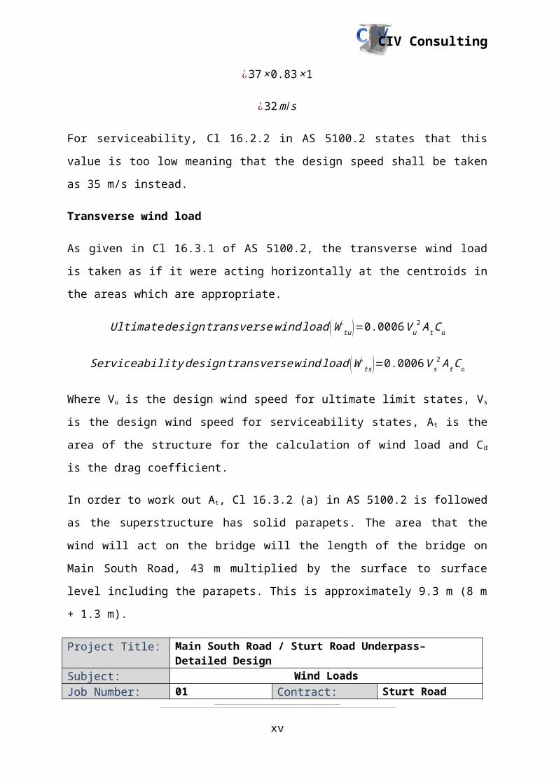
Transverse wind load
As given in Cl 16.3.1 of AS 5100.2, the transverse wind load is taken as if it were acting
horizontally at the centroids in the areas which are appropriate.
Ultimate design transverse wind load (W ¿tu)=0.0006 V u
2 A t Cd
Serviceability designtransverse wind load (W ¿ts)=0.0006 V s
2 A t Cd
Where Vu is the design wind speed for ultimate limit states, Vs is the design wind speed for
serviceability states, At is the area of the structure for the calculation of wind load and Cd is
the drag coefficient.
In order to work out At, Cl 16.3.2 (a) in AS 5100.2 is followed as the superstructure has solid
parapets. The area that the wind will act on the bridge will the length of the bridge on Main
South Road, 43 m multiplied by the surface to surface level including the parapets. This is
approximately 9.3 m (8 m + 1.3 m).
x

CIV Consulting
Project Title: Main South Road / Sturt Road Underpass– Detailed Design
Subject: Wind LoadsJob Number: 01 Contract: Sturt Road Bridge
DesignDate: 05/06/2014 Prepared: D TetSheet: 03 of 04 Checked: J NgoClient: DPTI Approved: J Rogers
At=length ×d epth
¿43× 9.3
¿400 m2
Cl 16.3.3 (a) in AS 5100.2 is followed in order to determine the Cd for the structure as well as
figure 16.3.3. This means working out the b/d ratio of the underpass, where b is the overall
width of the bridge between outer faces of parapets, which is 30.5 m, and depth of the
structure which has been previous stated
bd
ratio=30.59.3
¿3.3
Using figure 16.3.3, the drag coefficient is approximately 1.41.
W ¿tu=0.0006 × 402× 400 ×1.41
¿537 kN
W ¿ts=0.0006 ×352 × 400× 1.41
¿414 kN
Longitudinal wind load
In order to work out the longitudinal wind load, Cl 16.5 is to be followed for ultimate and
serviceability limit states.
Ultimate design vertical wind load (W ¿vu)=0.6 V u
2 A pCL 10−3
xi

CIV Consulting
Project Title: Main South Road / Sturt Road Underpass– Detailed Design
Subject: Wind LoadsJob Number: 01 Contract: Sturt Road Bridge
DesignDate: 5/06/2014 Prepared: D TetSheet: 04 of 04 Checked: J NgoClient: DPTI Approved: J Rogers
Serviceability design vertical wind load (W ¿vs )=0.6 V s
2 A pCL 10−3
The above equations can be used as the inclination of the bridge is less than 5°. Regardless,
the modelling of the bridge will be done in a flat plan for simplicity which is further
explained in section 1.5.1 under Super T Analysis. Ap is the bridge area in plan and CL is the
lift coefficient, which is provided as 0.75. Ap is the length of the bridge multiplied by how
wide it is. The length is 43 m and the width is 30.5 m.
Ap=43 ×30.5
¿1312 m2
W ¿vu=0.6 V u
2 Ap CL 10−3
¿0.6× 402× 1312× 0.75 ×10−3
¿937 kN
W ¿vs=0.6 V u
2 Ap CL 10−3
¿0.6×352×1312 ×0.75 ×10−3
¿723kN
xii
CIV Consulting
1.4.2. Earthquake loads
Project Title: Main South Road / Sturt Road Underpass– Detailed Design
Subject: Earthquake loadsJob Number: 01 Contract: Sturt Road Bridge
DesignDate: 05/06/2014 Prepared: C LiSheet: 01 of 07 Checked: J NgoClient: DPTI Approved: D Tet
For the design of bridge structures, earthquake effects shall be considered in accordance with
this Australian Standard AS5100.2-2004. Some factors to be used in the calculation of
earthquake effects which are in common with those given in AS1170.4 earthquake actions in
Australia.
1. The bridge classification: this bridge is classed as a Type 2 bridge: (that is designed to
carry large volumes of traffic or bridges over other roadways, railways or buildings)
2. The product of acceleration coefficient.
3. The site factors.
Acceleration coefficient:
a=0.1 in the Adelaide area: from table 2.3 (AS1170.4:1993)
Site factor: S=1.25 comprised of mainly stiff or hard clays or controlled fill from table 2.4 (a)
(AS1170.4:1993)
Hence:
a × S=0.1×1.25=0.125
And the bridge earthquake design category from table 14.3.1(AS 5100.2:2004) is BEDC-2
Requirements for category BEDC-2:
Static bridge analysis
Consider both horizontal and vertical earthquake forces
xiii

CIV Consulting
Project Title: Main South Road / Sturt Road Underpass– Detailed Design
Subject: Earthquake loadingJob Number: 01 Contract: Sturt Road Bridge
DesignDate: 05/06/2014 Prepared: C LiSheet: 02 of 07 Checked: J NgoClient: DPTI Approved: D Tet
Static analysis: Horizontal
The formula for horizontal forces is as described in 14.5.2 (AS5100.2:2004) and below
HU¿ =I (CS
R f )Gg
With the limits-
H U¿ ≥0.02 Gg
HU¿ ≤ I ( 2.5 a
Rf)Gg
Where:
- I= Importance factor=1 because it is a type 2 bridge from table 14.5.3 (AS5100.2)
- S= Site factor =1.25 (calculated above)
- R f = Structural response factor=3 from table 14.5.5 (AS5100.4:2004 Bridges with
simply supported spans)
- Gg= total un-factored dead load (calculated below)
- C= Earthquake design coefficient as described in 14.5.4 (AS5100.2 :2004) and below
For the earthquake design coefficient C, the equation is given as below:
C=1.25 a
T23
xiv
CIV Consulting
Project Title: Main South Road / Sturt Road Underpass– Detailed Design
Subject: Earthquake loadingJob Number: 01 Contract: Sturt Road Bridge
DesignDate: 05/06/2014 Prepared: C LiSheet: 03 of 07 Checked: J NgoClient: DPTI Approved: D Tet
Where:
a=0.1 (From AS1170.4:1993)
T=0.063√δ
Where:
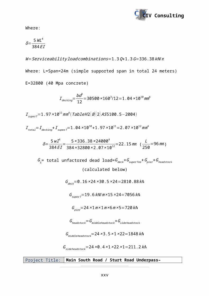
δ= 5WL4
384 EI
Where:W =Serviceability load combinations=1.3 Q+1.3 G=336.38 kN /m
Where: L=Span=24m (one simply supported span in total 24 meters)
E=32800 (40 Mpa concrete)
I decking=bd3
12=160∗305003 /12=3.78× 1014 mm4
I super T=1.97 × 1011mm4 (Table H 2 ( B ) (2 ) AS 5100.5−2004)
I total=I decking+ I superT=3.78 ×10¹⁴+1.97 × 1011=3.78 ×10¹⁴m m4
δ= 5 wl4
384 EI= 5× 336.38× 240004
384 × 32800× 3.78× 1014 =0.12 mm (L
250=176 mm)
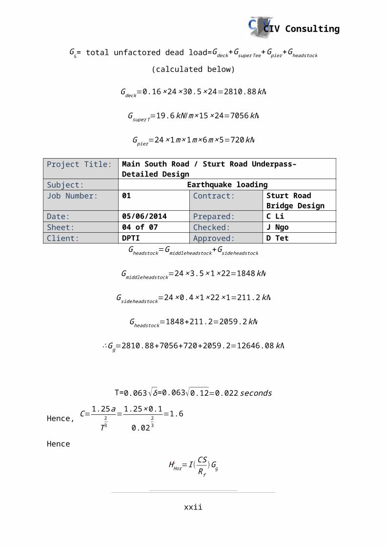
Gg= total unfactored dead load=Gdeck+G superTee+Gpier+Gheadstock (calculated below)
Gdeck=0.16 ×24× 30.5× 24=2810.88 kN
Gsuper T=19.6 kN /m ×15×24=7056 kN
G pier=24 ×1 m×1m× 6m× 5=720 kN
xv

CIV Consulting
Project Title: Main South Road / Sturt Road Underpass– Detailed Design
Subject: Earthquake loadingJob Number: 01 Contract: Sturt Road Bridge
DesignDate: 05/06/2014 Prepared: C LiSheet: 04 of 07 Checked: J NgoClient: DPTI Approved: D Tet
Gheadstock=Gmiddleheadstock+Gside headstock
Gmiddle headstock=24×3.5× 1× 22=1848 kN
Gside headstock=24 ×0.4 × 1× 22× 1=211.2kN
Gheadstock=1848+211.2=2059.2kN
∴Gg=2810.88+7056+720+2059.2=12646.08 kN
T=0.063√δ=0.063√0.12=0.022 seconds
Hence, C=1.25 a
T23
=1.25 × 0.1
0.0223
=1.6
Hence
H Hor¿ =I (CS
R f)G g
HU¿ =1 ×( 1.6× 1.25
3 )×12646.08=8430.72kN
Because
HU¿ =8430.72kN ≤ I( 2.5 a
R f )G g=1 × 2.5 ×0.13 × 8430.72=702.56 kN
∴Hhor¿ =702.56 kN=29.27 kN /m
xvi

CIV Consulting
Project Title: Main South Road / Sturt Road Underpass– Detailed Design
Subject: Earthquake loadingJob Number: 01 Contract: Sturt Road Bridge
DesignDate: 05/06/2014 Prepared: C LiSheet: 05 of 07 Checked: J NgoClient: DPTI Approved: D Tet
Static analysis: Vertical:
The formula for horizontal forces is as described in 14.5.2. (AS5100.2:2004) and below
H vert¿ =I ( CS
R f )Gg
Where:
I= Importance factor=1 because it is a type 2 bridge from table 14.5.3 (AS5100.2)
S=site factor=1.25 (calculated above)
R f=Structural response factor=3 (calculated above) from table 14.5.5 (AS5100.4:2004)
Gg= total un-factored dead load=Gdeck+G superTee+G pier+Gheadstock (calculated below)
C= Earthquake design coefficient as described in 14.5.4 (AS 5100.2:2004) and below
C=1.25 a
T23
For the earthquake design coefficient C, the equation is given as below:
C=1.25 a
T23
Where:
a=0.1 (From AS1170.4:1993)
T=0.063√δ
xvii

CIV Consulting
Project Title: Main South Road / Sturt Road Underpass– Detailed Design
Subject: Earthquake loadingJob Number: 01 Contract: Sturt Road Bridge
DesignDate: 05/06/2014 Prepared: C LiSheet: 06 of 07 Checked: J NgoClient: DPTI Approved: D TetWhere:
δ= 5 WL4
384 EI
W =Serviceability load combinations=1.3 Q+1.3 G=336.38 kN /m
Where: L=Span=24m (simple supported span in total 24 meters)
E=32800 (40 Mpa concrete)
I decking=bd3
12=30500× 1603/12=1.04 ×1010mm4
I super T=1.97× 1011mm4 (Table H 2 ( B ) (2 ) AS 5100.5−2004)
I total=I decking+ I superT=1.04 × 10¹⁰+1.97 × 1011=2.07× 10¹²m m4
δ= 5 wl4
384 EI= 5× 336.38× 240004
384 × 32800× 2.07 ×1012 =22.15 mm (L
250=96 mm)
Gg= total unfactored dead load=Gdeck+G superTee+Gpier+Gheadstock (calculated below)
Gdeck=0.16 ×24× 30.5× 24=2810.88 kN
Gsuper T=19.6 kN /m ×15×24=7056 kN
G pier=24 ×1 m×1m× 6m× 5=720 kN
Gheadstock=Gmiddleheadstock+Gside headstock
Gmiddle headstock=24×3.5× 1× 22=1848 kN
Gside headstock=24 ×0.4 × 1× 22× 1=211.2kN
xviii
CIV Consulting
Project Title: Main South Road / Sturt Road Underpass– Detailed Design
Subject: Earthquake loadingJob Number: 01 Contract: Sturt Road Bridge
DesignDate: 05/06/2014 Prepared: C LiSheet: 07 of 07 Checked: J NgoClient: DPTI Approved: D Tet
Gheadstock=1848+211.2=2059.2 kN
∴Gg=2810.88+7056+720+2059.2=12646.08 kN
T=0.063√δ=0.063√22.15=0.3 seconds
Hence, C=1.25 a
T23
=1.25 × 0.1
1.9723
=0.28
H vert¿ =I ( CS
R f )Gg
H❑¿ =1 ×( 0.28× 1.25
3 )×12646.08=1481.3 kN=61.72 kN /m
However, according to section 14.5.6 of (AS5100.2:2004) the vertical earthquake force shall
not be less than 50% of the maximum horizontal earthquake force in either direction. And the
vertical earthquake force could be considered independently of the horizontal earthquake
forces.
∴H vert¿ =61.72 kN /m
xix

CIV Consulting
Project Title: Main South Road / Sturt Road Underpass– Detailed Design
Subject: Dead LoadsJob Number: 01 Contract: Sturt Road Bridge
DesignDate: 29/05/2014 Prepared: A GreigSheet: 01 of 01 Checked: J NgoClient: DPTI Approved: D Tet
1.4.3. Dead loads
Dead Load of Structure
AS 5100.2 Cl 5 defines dead loads as two separate quantities. The first being the dead load of
the structure, this takes into account the self-weight of all the structural elements and any
non-structural elements that will unlikely change during construction and use of the structure.
In this case, the dead loads of the structure contain:
- Super T self-weight (Calculated by software, SPACE GASS)
- Decking self-weight: 7.68 kN/m, load width used was 2m which is the width of a
super T (defined in Decking Design, section 1.7)
- Parapet self-weight: 13kN/m (defined in Parapet, section 1.11.1)
The load factor for the dead load of the structure can be taken for ultimate design and
serviceability can be taken from AS5100.2 T 5.2. In this case:
- Ultimate Design: 1.2G
- Serviceability: 1G
Super imposed Dead Load
The second dead load to consider is the super imposed dead load which is the self-weight of
all the non-structural elements that can be removed. In this case the superimposed dead loads
are:
- Bitumen (24.5 kN/m3, given from Earthworks/ Road works Department)
- Services (1 kPa)
xx

CIV Consulting
Project Title: Main South Road / Sturt Road Underpass– Detailed Design
Subject: Traffic LoadsJob Number: 01 Contract: Sturt Road Bridge
DesignDate: 29/05/2014 Prepared: A GreigSheet: 01 of 01 Checked: J NgoClient: DPTI Approved: D Tet
1.4.4. Traffic loads
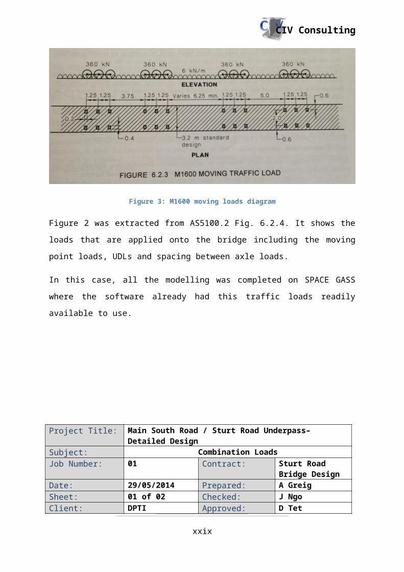
AS5100.2 Cl 6.2.3 defines the moving traffic loads that will be the most critical case for the
Sturt Road Bridge. The vehicle length has been taken as 25m.
Figure 3: M1600 moving loads diagram
Figure 2 was extracted from AS5100.2 Fig. 6.2.4. It shows the loads that are applied onto the
bridge including the moving point loads, UDLs and spacing between axle loads.
In this case, all the modelling was completed on SPACE GASS where the software already
had this traffic loads readily available to use.
xxi
CIV Consulting
Project Title: Main South Road / Sturt Road Underpass– Detailed Design
Subject: Combination LoadsJob Number: 01 Contract: Sturt Road Bridge
DesignDate: 29/05/2014 Prepared: A GreigSheet: 01 of 02 Checked: J NgoClient: DPTI Approved: D Tet
1.4.5. Combination loads
The load factor for the dead load of the structure can be taken for ultimate design and
serviceability can be taken from AS5100.2 T 5.3. In this case:
- Ultimate Design: 2G
- Serviceability: 1.3G
The load factor for the traffic loads will need to be calculated. This can be found in AS1500.2
Cl. 6.7.2, “Dynamic Load Allowance, Magnitude.”
(1+α )× theload factor× the actionunder consideration
The Dynamic Load Allowance (α ) can be taken from AS5100.2 T6.7.2. For an M1600 load, it
is given as 0.3.
The load factor can be given from AS5100.2 T6.10 (A). For an M1600 moving traffic load,
the values can be taken as:
- Ultimate: 1.8
- Serviceability: 1
Hence the ultimate limit state can be given as:
Ultimate Traffic Load Factor= (1+0.3 )× 1.8
Ultimate Traffic Load Factor=2.34
The serviceability state can be given as:
Serviceability Traffic Load Factor=(1+0.3 )× 1
Serviceability Traffic Load Factor=1.3
xxii

CIV Consulting
Project Title: Main South Road / Sturt Road Underpass– Detailed Design
Subject: Combination LoadsJob Number: 01 Contract: Sturt Road Bridge
DesignDate: 29/05/2014 Prepared: A GreigSheet: 02 of 02 Checked: J NgoClient: DPTI Approved: D Tet
All load factors and loads have been applied into SPACE GASS to analyse the moving loads
under different positions on the bridge to account for the worst possible case which will be
detailed in section 1.5.1, Super T Analysis.
A UDL was given for the traffic loads and this was applied to each of the super T’s.
Pedestrian loads were not considered due to the traffic load giving the worst case. Hence all
the Super T’s have the same reinforcement and the worst case of the vehicle would govern
the worst case of pedestrian.
The load factor can be given from AS5100.2 T6.10 (A). For an M1600 moving traffic load,
the values can be taken as:
- Ultimate: 1.8
- Serviceability: 1
Hence the ultimate limit state can be given as:
Ultimate Traffic Load Factor= (1+0.3 )× 1.8
Ultimate Traffic Load Factor=2.34
The serviceability state can be given as:
Serviceability Traffic Load Factor=(1+0.3 )× 1
Servi ceability Traffic Load Factor=1.3
All load factors and loads have been applied into SPACE GASS to analyse the moving loads
under different positions on the bridge to account for the worst possible case, which will be
detailed in section 1.5.1, Super T Analysis.
xxiii

CIV Consulting
1.5.Structural Analysis
1.5.1. Super T analysis
In order to do the structural analysis of the Super T’s SPACE GASS was used as the
modelling software. Figure 3 shows the rendered version of the super T’s with the vehicle
loadings being applied to the bridge at an arbitrary point in time (may not be worst case). The
load cases defined in Dead Loads (section 1.4.3) and Traffic Loads (Section 1.4.4) have all
been inputted into SPACE GASS to give an ultimate result to begin design calculations.
Figure 4: Vehicle axles applied to bridge
From this analysis, the maximum bending moment on each Super T can be found as well as
all the shear forces and reaction forces that can be taken into account for the load transfer to
the headstock. The connection between the headstock and Super T is taken as a pinned
connection as transferring moment is not a good option on bridges.
When the analysis was run, a total of 186 different load cases due to the moving axle
locations have been defined and enveloped to find the worst-case scenario. The analysis
showed that the fourth Super T from the edge is the most critical which produces the worst-
case scenario for bending moment. Figure 5 shows the maximum bending moment at mid
span of the fourth super T in from the edge. The grey lines to the left and right of the bending
moment diagram are the other super T’s which have been filtered out to clearly show the
ultimate bending moment.
xxiv
CIV Consulting
Figure 5: Maximum bending moment (mid span of critical Super T)
Figure 6 displays the shear force of the worst-case Super T from the edge that has the
maximum negative shear force.
Figure 6: Maximum shear force (end restraints of worst-case Super T)
Table 1 displays all the critical cases that need to be considered for design. It is important to
note that the load cases have been enveloped to give the worst case on every situation so table
1’s results may not be at equilibrium:
xxv

CIV Consulting
Table 1: Ultimate Design Loads
Ultimate Case Load/MomentMoment 4775 kNmPositive Shear Force at Abutment 1542 kNNegative Shear Force at Abutment -1589 kNReaction at Abutment 1543 kNPositive Shear Force at Columns 1305 kNNegative Shear Force at Columns -1444 kNReaction at Column 2320 kN
Since all the Super T’s have been tied together properly (similar during construction from the
use of connectors) in the analysis model, the load distribution between every super T was
even so all the ultimate moments and shear forces were very similar. This means there was an
even load distribution due to the decking, so the design for all components can be taken from
the ultimate values from table 1.
Since there was such great load distribution between the Super T’s the shear force at one end
of the super T may not equal the shear force at the end of the restraint as displayed in table 1.
1.5.2. Headstock analysis
Modeling’s of the headstocks at each abutment and at mid-span were undertaken using
SPACE GASS structural analysis software. The loads acquired from structural analysis of the
Super T Bridge (section 1.5) were applied directly to simulate the loading conditions. These
factored loads were applied as concentrated loads at the location of each super T rather than
applying a conservative UDL to the headstocks. Structural analysis provides the critical
bending moments, shear forces, support reactions and displacements required for design
purposes.
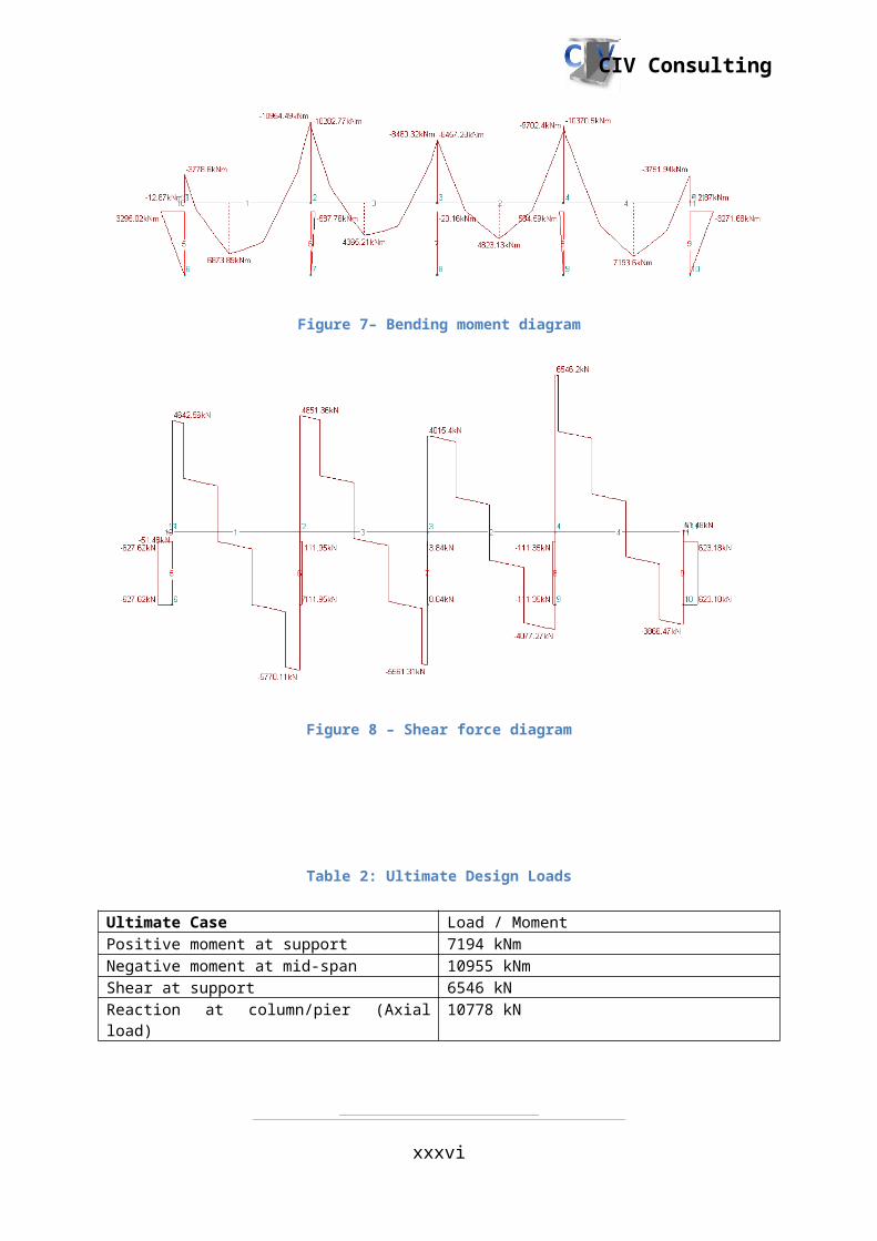
Headstock at mid-span
The mid-span headstock was modeled as a continuous beam supported by pinned columns to
ensure no moment was transferred to the pile cap beneath. As a result traditional bending
moment and shear force diagrams were produced as shown in figures 7 and 8. The design
actions can be seen in Table 2.
xxvi

CIV Consulting
Figure 7– Bending moment diagram
Figure 8 – Shear force diagram
Table 2: Ultimate Design Loads
Ultimate Case Load / MomentPositive moment at support 7194 kNmNegative moment at mid-span 10955 kNmShear at support 6546 kNReaction at column/pier (Axial load) 10778 kN
xxvii

CIV Consulting
Headstocks at abutments
Both abutment headstocks share the same design; this was modeled as a continually
supported beam, however the secant pile wall support had spring restraints to simulate the
effects of bearing on soil. Due to the concentrated loads from the Super T Bridge this created
a series of small bending moments and shear surrounding each Super T. Figure 9 shows a
typical pile sitting beneath the transferred load, which governed the design. The design
actions can be seen in Table 3.
Figure 9 - Abutment bending and shear diagram
Table 3: Ultimate Design Loads
Ultimate Case Load / MomentPositive moment 261 kNmNegative moment 110 kNmShear force 784 kN
Deflection
Short-term deflection was analyzed for each headstock. Figure 9 shows the maximum short-
term deflection incurred by the headstock at mid-span. This value is well below the
recommended maximum of 25mm. The headstocks at each abutment experience no
deflection due to the nature of their supports.
xxviii
CIV Consulting
Figure 10 – Short term deflection of headstock at mid-span
1.5.3. Column/secant pile wall analysis
To design the reinforcement of the pile wall supporting the bridge, column charts are selected
as it is a more effective and simpler way to design it. Several column charts have been
considered as shown in figure 11 below.
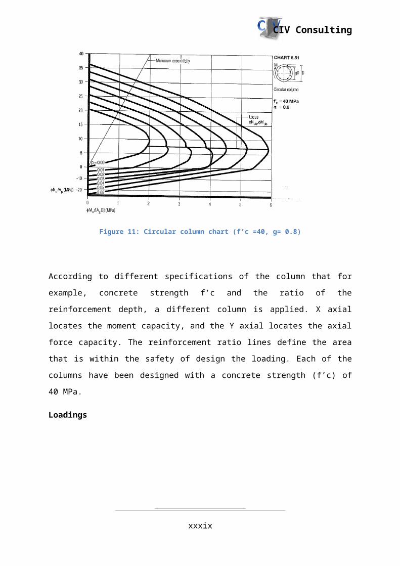
Figure 11: Circular column chart (f’c =40, g= 0.8)
xxix

CIV Consulting
According to different specifications of the column that for example, concrete strength f’c
and the ratio of the reinforcement depth, a different column is applied. X axial locates the
moment capacity, and the Y axial locates the axial force capacity. The reinforcement ratio
lines define the area that is within the safety of design the loading. Each of the columns have
been designed with a concrete strength (f’c) of 40 MPa.
Loadings
Figure 12: Bridge loading
Figure 12 above shows the indicated axial load from the bridge. The first and last loadings
are given as a UDL (universally distributed load) due to it being a pile wall. The middle
supports are five piers that to be designed as column structure. The load has been taken 6500
kN as this is the worse design situation of the five piers.
xxx

CIV Consulting
Figure 13: Loading form soil
The loading from the soil is only applied to the pile wall as they are soil pressure of the soils
adjacent to the underpass. The soil pressure has been converted as single shear force with
height aapproximately 2.9 m for design purpose.
xxxi

CIV Consulting
1.6.Super T Design
Project Title: Main South Road / Sturt Road Underpass– Detailed Design
Subject: Super T DesignJob Number: 01 Contract: Sturt Road Bridge
DesignDate: 05/06/2014 Prepared: D TetSheet: 01 of 09 Checked: A GreigClient: DPTI Approved: J RogersThrough the analysis of the Super T beams in the program “SPACEGASS” in section 1.5.1,
the values obtained can be used in order to design the reinforcement as well as the
prestressing that will be required for the design. This table of values have been given in Table
1 of section 1.5.1 (Super T Analysis). The Super T will be designed as a fully prestressed
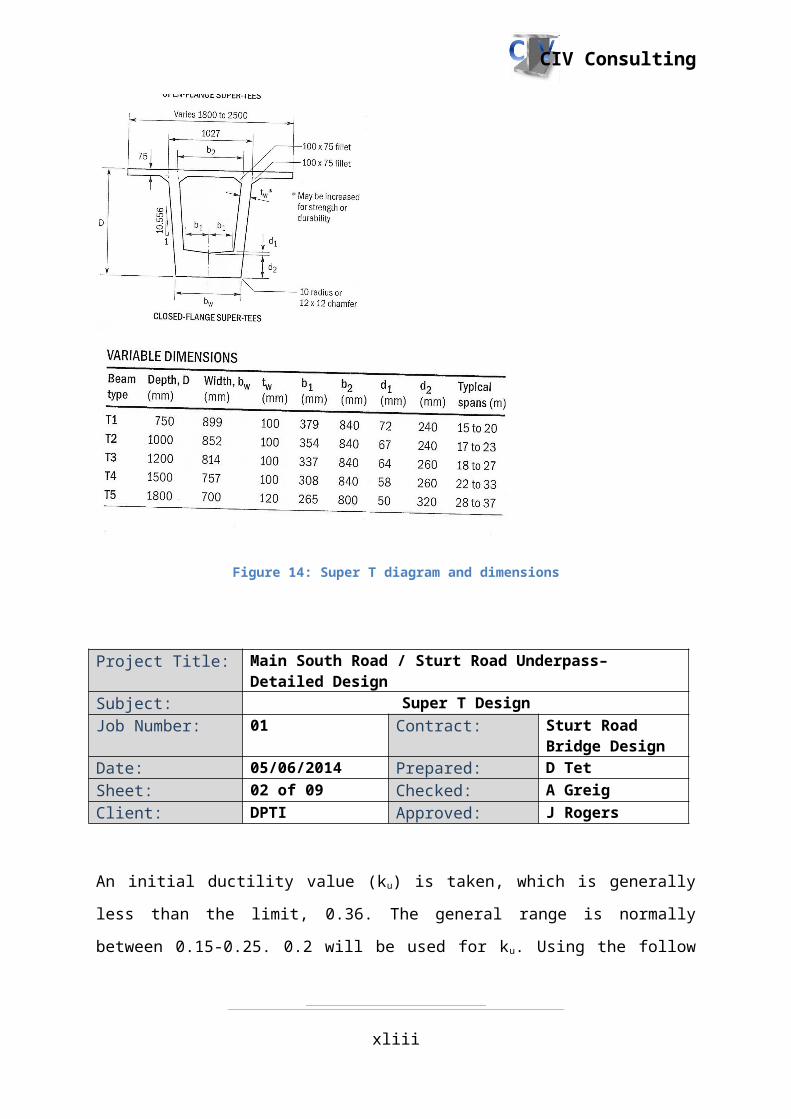
section. Below, Figure 14 is the dimension of the Super T, which is a national template. The
dimensions correspond with properties of a T4 Super T. The diameter of the strands has been
chosen as 15.2 mm.
Figure 14: Super T diagram and dimensions
xxxii

CIV Consulting
Project Title: Main South Road / Sturt Road Underpass– Detailed Design
Subject: Super T DesignJob Number: 01 Contract: Sturt Road Bridge
DesignDate: 05/06/2014 Prepared: D TetSheet: 02 of 09 Checked: A GreigClient: DPTI Approved: J Rogers
An initial ductility value (ku) is taken, which is generally less than the limit, 0.36. The general
range is normally between 0.15-0.25. 0.2 will be used for ku. Using the follow process below
will determine if this ductility chosen is sufficient.
b d2 ≥ M ¿
∅ α2 f 'c γ ku(1−
γ ku
2 )
Where:
b = 2000 mm, D = 1660(1500mm super T depth plus 160mm of decking) mm, cover = 50 mm, d = D – dc –(15.2 mm diameter strand/2)= 1552.4 mm, ∅=0.8. F’c is given as 40 MPa. α 2=1−0.003 f '
c
¿1−0.003× 40
¿0.88
As this is larger than 0.85, 0.85 is used instead from Cl 8.1.3 (b) in AS3600.
γ=1.05−0.007 f 'c
¿1.05−0.007 ×40
¿0.77
∴2000 ×1552.42≥ 4775 ×103
0.8× 0.85 × 40× 0.77×0.2 ×(1−0.77×0.252 )
xxxiii

CIV Consulting
4.8 × 10⁹≥ 1.2 ×10⁹ ∴ sufficent
Project Title: Main South Road / Sturt Road Underpass– Detailed Design
Subject: Super T DesignJob Number: 01 Contract: Sturt Road Bridge
DesignDate: 05/06/2014 Prepared: D TetSheet: 03 of 09 Checked: A GreigClient: DPTI Approved: J Rogers
In order to determine the amount of prestressing that will be required, the stresses at the top
and bottom of the Super T can be used in order to work out the initial prestressing force, p i.
Generally, the top tensile stress at transfer shouldn’t exceed 0.6√40¿3.79 MPa) and the
bottom tensile stress under full load shouldn’t exceed 0.6√40¿3.79 MPa). The section
modulus of the Super T is given below. These values are from AS 5100.5 appendix H table
H2 (B) (2). The only additional part is for the top which includes the decking section
modulus.
Ztop=Z top for Super T+Z for Decking
¿268 ×106+2000 × (160 )2
6=2.77 ×108mm4
Zbottom=257.8 × 106 mm4
σtop=nPiAg
−n PieZtop
+ MZtop
σbottom=nPiAg
+ n Pi eZ bottom
+ MZbottom
Where n=1, Ag has been given in AS 5100.5 Table H2 (B) (2) which is 627.1 x 103 mm2 plus
the area of the deck which is 320 x103 mm4 and M is M*. This means Ag is calculated to be
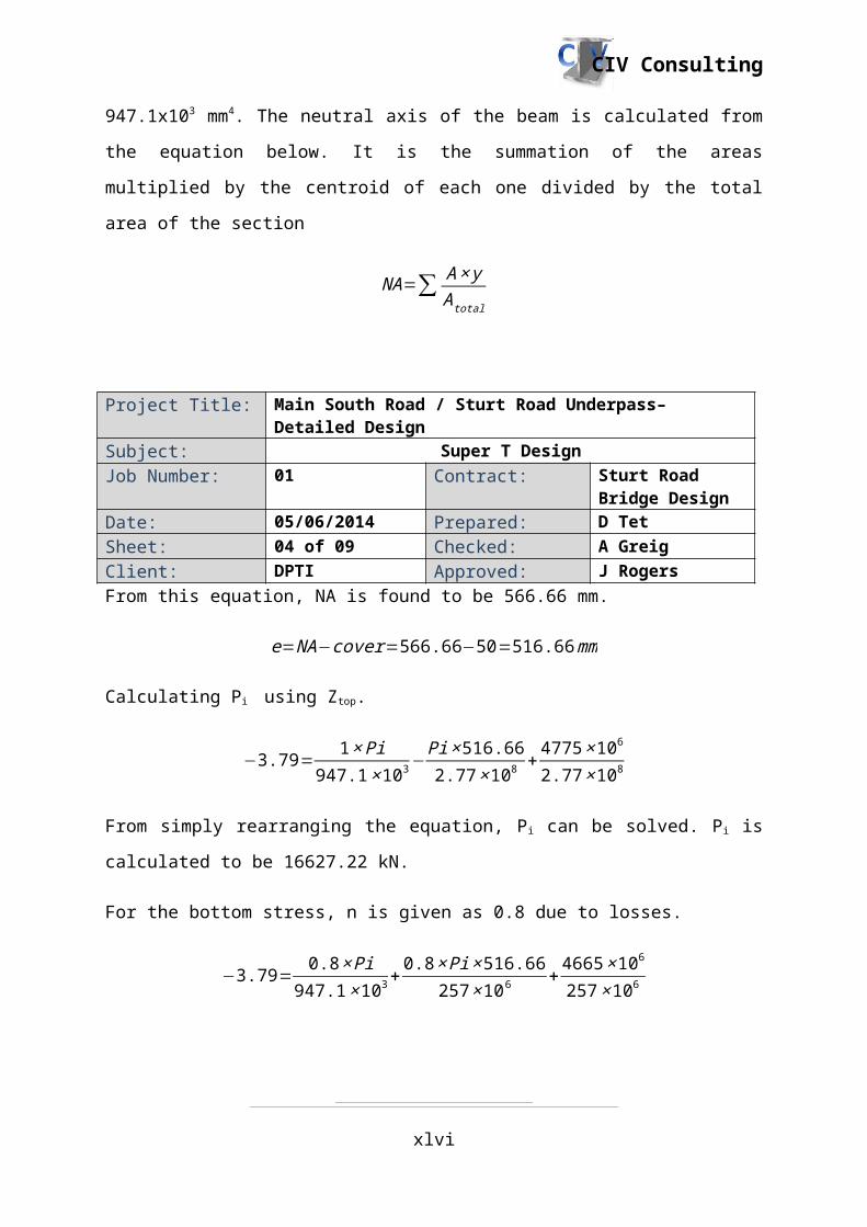
947.1x103 mm4. The neutral axis of the beam is calculated from the equation below. It is the
summation of the areas multiplied by the centroid of each one divided by the total area of the
section
NA=∑ A × yA total
xxxiv

CIV Consulting
Project Title: Main South Road / Sturt Road Underpass– Detailed Design
Subject: Super T DesignJob Number: 01 Contract: Sturt Road Bridge
DesignDate: 05/06/2014 Prepared: D TetSheet: 04 of 09 Checked: A GreigClient: DPTI Approved: J RogersFrom this equation, NA is found to be 566.66 mm.
e=NA−cover=566.66−50=516.66 mm
Calculating Pi using Ztop.
−3.79= 1 × Pi947.1 ×103 −
Pi×516.662.77 ×108 + 4775 ×106
2.77 ×10⁸
From simply rearranging the equation, Pi can be solved. Pi is calculated to be 16627.22 kN.
For the bottom stress, n is given as 0.8 due to losses.
−3.79= 0.8 × Pi947.1 ×103 + 0.8× Pi×516.66
257 ×106 + 4665 ×106
257 ×106
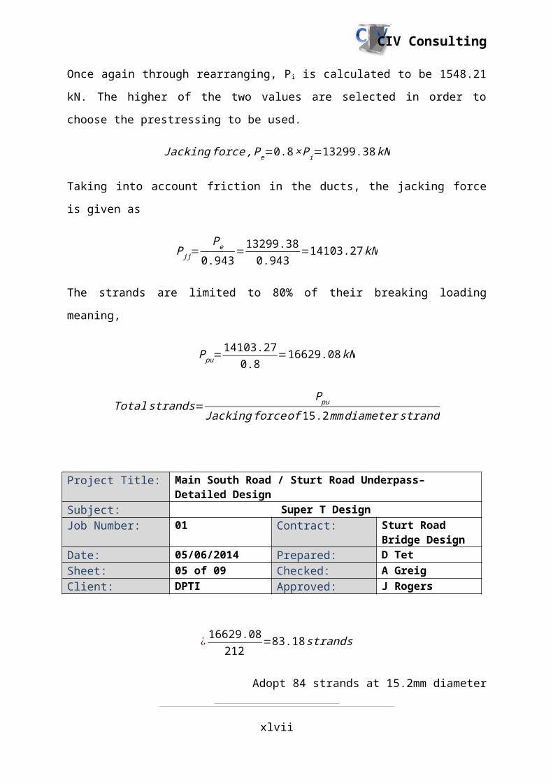
Once again through rearranging, Pi is calculated to be 1548.21 kN. The higher of the two
values are selected in order to choose the prestressing to be used.
Jacking force , Pe=0.8 × Pi=13299.38 kN
Taking into account friction in the ducts, the jacking force is given as
P jj=Pe
0.943=13299.38
0.943=14103.27 kN
The strands are limited to 80% of their breaking loading meaning,
Ppu=14103.27
0.8=16629.08 kN
Total strands=Ppu
Jacking forceof 15.2 mmdiameter strand
xxxv
CIV Consulting
Project Title: Main South Road / Sturt Road Underpass– Detailed Design
Subject: Super T DesignJob Number: 01 Contract: Sturt Road Bridge
DesignDate: 05/06/2014 Prepared: D TetSheet: 05 of 09 Checked: A GreigClient: DPTI Approved: J Rogers
¿ 16629.08212
=83.18 strands
Adopt 84 strands at 15.2mm diameter
A check is done to see if any reinforcement is required to be added for Mu.
M u=Apt σ pu z p
σ pu=f pb(1−k1k 2
γ)
K1 is given as AS 3600 Cl 8.1.7 for bonded tendons. Each strand has a nominal area of 143
mm2. Fpb is given as 1750 MPa.
k 2=1
b d p f 'c
( Apt f pb)
¿ 12000× 1552.4 f '
c
(84 × 143 ×1750 )
¿0.17
σ pu=1750(1−0.4 × 0.170.77 )
¿1596.88 kN
Taking account 20% of losses, fpy is given as 1357.34 kN.
z p=1552.4 (1−0.77 × 0.2× 12)
xxxvi

CIV Consulting
¿1432.87 mm
Project Title: Main South Road / Sturt Road Underpass– Detailed Design
Subject: Super T DesignJob Number: 01 Contract: Sturt Road Bridge
DesignDate: 05/06/2014 Prepared: D TetSheet: 06 of 09 Checked: A GreigClient: DPTI Approved: J Rogers
M u=Apt σ pu z p
¿(84 ×143)× 1596.88 ×1432.87
¿22551 kNm
As it is greater than 5965.75 kN (M*/0.8), it is sufficient. The amount of strands can be
decreased by half in order to have a reasonable amount (Mu=13742.45 kNm)
Adopt 42 strands at 15.2mm diameter as it is sufficient
Web shearing
As this is a Super T, web shearing will need to be looked at as opposed to flexural shear as
this will create the most critical case.
V uc=V t+PV
Pv=Pe × 4 hL
¿6006 ×( 4× 516.6624000 )
¿613.38 kN
In order to work out Vt, the process of using Mohr’s circle is used
The second moment of inertia of the Super T is to be calculated, as shown below. I is given
for the Super T in AS 5100.5 Table H2 (B) (2) as 197320 x 106 mm4). I for the deck is to be
calculated
xxxvii

CIV Consulting
I deck=2000 ×1602
12
Project Title: Main South Road / Sturt Road Underpass– Detailed Design
Subject: Super T DesignJob Number: 01 Contract: Sturt Road Bridge
DesignDate: 05/06/2014 Prepared: D TetSheet: 07 of 09 Checked: A GreigClient: DPTI Approved: J Rogers
¿6.82 ×108 mm4
I g=197320 ×106+6.82× 10⁸
¿1.98 ×1011mm4
σ cx=MyI
−Pe
Ag−
Pe eyI
¿ 4775 ×106
1.98× 10¹¹−7123 ×103
947100−7123× 103× 516.66× 566.66
1.98× 10¹¹
¿−18.03 MPa
τ xy=V t ×Q
I bv
Where Q is shown below
Q= (2000× 200 )×(566.66−( 2352 ))+(757 ×(566.66−( 235
2 )2 ))
¿2.11×10⁸m m3
The following two equations are used to work out Vt
τ xy=V t ×Q
I bv
xxxviii
CIV Consulting
Where bv is equal to 577 mm.
Project Title: Main South Road / Sturt Road Underpass– Detailed Design
Subject: Super T DesignJob Number: 01 Contract: Sturt Road Bridge
DesignDate: 05/06/2014 Prepared: D TetSheet: 08 of 09 Checked: A GreigClient: DPTI Approved: J RogersThe following two equations are used to work out Vt
τ xy=V t ×Q
I bv
Where bv is equal to 577 mm.
σ c1=0.36√ f 'c=√ (σcx 0.5 )2+ τxy
2+0.5 σ cx
σ c1=0.36√40=√(−18.03 ×0.5 )2+( V t ×2.11×10⁸
1.98× 1011×577 )2
+0.5× (−18.03 )
Through rearranging the equation, Vt can be solved which calculated to be 3667 kN.
∴V uc=3667+613.38=4280.4 kN
∅ 0.5V uc=0.7× 0.5 ×4280.4=1498.14 kN
As this value is larger less the worst case V* as shown in section 1.5.1, this means that Vu.min
needs to be calculated.
V u , min=V uc +0.10√ f 'c bv do≥ V uc+0.6 bv do
¿4465.24+0.10√40 × .577 × .1425≥ 4465.24+0.6 × .577 × .1425
¿Φ 4800 kN ≥Φ 4280.9 kN
¿3360.3 kN
As ΦVu, min is greater than V*, minimum area of shear steel used to determine it.
xxxix

CIV Consulting
A sv , min=0.06√ f 'c bv(
sf sv ,min
)≥+0.35 bv(s
f sv , min)
Project Title: Main South Road / Sturt Road Underpass– Detailed Design
Subject: Super T DesignJob Number: 01 Contract: Sturt Road Bridge
DesignDate: 05/06/2014 Prepared: D TetSheet: 09 of 09 Checked: A GreigClient: DPTI Approved: J Rogers
A sv ,min
s=0.06√40 ×(577
500 )≥+0.35×( 577500 )
¿1.52 mm2/mm
Using either 0.75D or 500 as the spacing, try 2N24 @ 500 cts
A sv ,min
s=2 × 450
500
¿1.8mm2/mmok but can go smaller
Try 6N12 @ 400 cts
A sv ,min
s6× 110
400
¿1.65 mm2/mm
Adpot 6N12 ligs @400 cts
xl

CIV Consulting
1.7.Decking Design
Project Title: Main South Road / Sturt Road Underpass– Detailed Design
Subject: Decking DesignJob Number: 01 Contract: Sturt Road Bridge
DesignDate: 05/06/2014 Prepared: M EaSheet: 01 of 18 Checked: A GreigClient: DPTI Approved: D TetLoad combinations considered are as followed:
Ultimate limit state combination
PE + ultimate traffic load
PE + ultimate pedestrian traffic loads
PE + ultimate wind loads
PE + earthquakes
Serviceability limit state combination
PE + ultimate traffic load + 0.7*ultimate pedestrian traffic loads
PE + ultimate traffic load + 0.7*ultimate pedestrian traffic loads + 0.5*ultimate wind load
PE + ultimate traffic load + 0.7*ultimate pedestrian traffic loads + 0.5*earthquakes
SPACEGASS Analysis
The deck is designed as a one-way slab transversely across the width of the bridge by having
the Super T beam web underneath as supports. The distance between the supports is 1m. A
variety of positions for truck wheels are placed as eccentrically as possible to give adverse
effects. The loadings applied here is the same as the loadings used for Super T analysis
which is complied to AS5100.2.
xli

CIV Consulting
Project Title: Main South Road / Sturt Road Underpass– Detailed Design
Subject: Decking DesignJob Number: 01 Contract: Sturt Road Bridge
DesignDate: 05/6/2014 Prepared: M EaSheet: 02 of 18 Checked: A GreigClient: DPTI Approved: D Tet
Figure 15: Deck ultimate design moments
Figure 16: Deck serviceability design moments
Bending Strength
Ultimate: 𝑀∗=26.505𝑘𝑁𝑚 𝑜𝑟 𝑀∗=−14.696𝑘𝑁𝑚xlii
CIV Consulting
Serviceability: 𝑀∗=14.818𝑘𝑁𝑚 𝑜𝑟 𝑀∗=−12.480𝑘𝑁𝑚𝑓′c = 40𝑀𝑃𝑎 𝑓sy = 500𝑀𝑃𝑎𝐸c=32.8𝐺𝑃𝑎 𝐸s=200𝐺𝑃𝑎Project Title: Main South Road / Sturt Road Underpass– Detailed Design
Subject: Decking DesignJob Number: 01 Contract: Sturt Road Bridge
DesignDate: 05/6/2014 Prepared: M EaSheet: 03 of 18 Checked: A. GreigClient: DPTI Approved: D Tet
Exposure Classification: B1, Minimum cover: 40mm𝐷=160𝑚𝑚, Try N12 bars top and bottom𝑑 = 160−40−12/2 = 114𝑚𝑚Design for 1m wide strip 𝛼2 = 0.85
γ=0.85−0.007 (f c '−28)
γ=0.85−0.007 ×(40−28)
γ=0.766
f cf' =0.6√ f c
'
f cf' =0.6 ×√40
f cf' =3.79
Minimum design bending moment:
According to AS5100.2, clause 8.1.4.1, the ultimate strength in bending (Muo) shall not be less
than (Muo)min cacculated below.
M uo ,min=1.2[Z ( f cf ’+ PA s )+P e ]
Where Z = bD2
6 = 1000∗1602
6 = 4.27 × 106 mm3
M uo ,min=1.2 ×[4.27× 106 ×(3.79+0)+0]
M uo ,min=19.4 kNm
xliii

CIV Consulting
A s tmin=0.0025 bd
A s tmin=0.0025 ×1000 ×114
A s tmin=285 mm2
Project Title: Main South Road / Sturt Road Underpass– Detailed Design
Subject: Decking DesignJob Number: 01 Contract: Sturt Road Bridge
DesignDate: 05/06/2014 Prepared: M EaSheet: 04 of 18 Checked: A GreigClient: DPTI Approved: D Tet
Top Reinforcement (Negative)
M uo=14.70.8
=18.37 kNm< M uo , min
M uo ,min=19.4 kNm
Z ≈ 0.925 d=0.925× 114
Z=105.45 mm
M u o=A st f sy Z
A st=M uof sy Z
A st=19.4 ×10 6
500× 105.45=368 mm 2
Try N 12 bars at 275 cts(400 mm2/m)
T=A st f sy
T=440× 500
T=200 kN
C=T=0.85 f c ’ γk udb
ku=200× 103
0.85× 40×0.766 × 1000× 114
xliv

CIV Consulting
ku=0.067<0.36, ductility is OK
Project Title: Main South Road / Sturt Road Underpass– Detailed Design
Subject: Decking DesignJob Number: 01 Contract: Sturt Road Bridge
DesignDate: 05/06/2014 Prepared: M EaSheet: 05 of 18 Checked: A GreigClient: DPTI Approved: D Tet
M uo=200 ×(0.114−0.5 × 0.766 ×0.067 ×0.114 )
M uo=22.2 kNm
ϕ M uo=0.8 ×22.2=17.8 kNm
ϕ M uo>M∗¿14.7 kNm¿)
Adopt N12 bars at 275cts
xlv
CIV Consulting
Project Title: Main South Road / Sturt Road Underpass– Detailed Design
Subject: Decking DesignJob Number: 01 Contract: Sturt Road Bridge
DesignDate: 05/06/2014 Prepared: M EaSheet: 06 of 18 Checked: A GreigClient: DPTI Approved: D TetBottom Reinforcement (Positive)
M u o=26.5050.8
=33.1 kNm
Z ≈ 0.925 d
Z=0.925×114
Z=105.45 mm
M uo=A st f sy Z
A st=M uof sy Z
¿ 33.1 ×10⁶
500× 105.45=628 mm2
Try N 12 bars at 175 cts(629 mm2m )
T=A st f sy
T=629 ×500
T=315 kN
C=T=0.85 f c ’ γk udb
ku=315× 103
0.85× 40×0.766 × 1000× 114
ku=0.106<0.36, ductility is OK
xlvi
CIV Consulting
Project Title: Main South Road / Sturt Road Underpass– Detailed Design
Subject: Decking DesignJob Number: 01 Contract: Sturt Road Bridge
DesignDate: 05/06/2014 Prepared: M EaSheet: 07 of 18 Checked: A. GreigClient: DPTI Approved: D Tet
M uo=315 × (0.114−0.5 ×0.766 × 0.106× 0.114 )
Muo =34.5𝑘𝑁𝑚ϕ M uo=0.8∗34.5=27.6 kNm
ϕM uo>M∗¿26.5 kNm (Ok)Use N12 at 275cts top and N12 at 175cts bottom in primary direction
xlvii
CIV Consulting
Project Title: Main South Road / Sturt Road Underpass– Detailed Design
Subject: Decking DesignJob Number: 01 Contract: Sturt Road Bridge
DesignDate: 05/06/2014 Prepared: M EaSheet: 08 of 18 Checked: A. GreigClient: DPTI Approved: D TetCrack Control
Crack Control for Flexure (AS5100.5 clause 9.4.1)
The centre-to-centre spacing of bars in each direction shall be not greater than the
lesser of 2.0Ds or 300mm. Maximum spacing = min(2*160, 300) = 300mm.
The steel stress (fscr) calculated shall not exceed the maximum steel stress given in
Table 9.4.1(A). From this table, maximum Steel Stress, 𝑓scr = 295𝑀𝑃𝑎.
Calculate stress in steel assuming section is cracked, assuming top steel is in tension
Positive
n=Es
E c
n= 20032.8
n=6.1 ≈6.5
A st 1=550 mm2
A st 2=400 m m2
b×d❑n
2
2+ (n−1 ) A st 2(d❑n−d2)=n A st 1(d1−dn)
1000 ×d❑n
2
2+(6.5−1)∗400∗(dn−46)=6.5∗550∗(114−dn)
500 dn2+2200 dn – 101200=407550 – 3575 dn
500 dn2+5775 dn−306350=0
dn = 19.6mm above top steel
xlviii

CIV Consulting
Project Title: Main South Road / Sturt Road Underpass– Detailed Design
Subject: Decking DesignJob Number: 01 Contract: Sturt Road Bridge
DesignDate: 05/06/2014 Prepared: M EaSheet: 09 of 18 Checked: A GreigClient: DPTI Approved: D Tet
I cr=b dn
3
3+(n−1 ) A st 2 ( dn−d2 )2+n A st 1 (d1−dn )2
= 1000*(19.6)3/3 + (6.5-1)*400*(19.6-46)2 + 6.5*550*(114-19.6)2
I cr=1000× (19.6 )3
3+(6.5−1 )× 400 × (19.6−46 )2+6.5× 550× (114−19.6 )2
I cr=33× 106 mm4
σ st 1=M yI cr
σ st 1=14.818× (46−19.6 )
33×106
σ st 1=11.9 MPa<295 MPa Ok
σ st 2=MyIcr
σ st 2=14.818× (114−19.6 )
33 ×106
σ st 2=42.4 MPa<295 MPaOk
The calculated steel stress (fscr) shall not exceed 0.8fsy.
0.8fsy = 0.8*500 = 400MPa
As above, 𝜎st1=11.9𝑀𝑃𝑎<400𝑀𝑃𝑎 (Ok)𝜎st2=42.4𝑀𝑃𝑎<400𝑀𝑃𝑎 (Ok)
xlix

CIV Consulting
l

CIV Consulting
Project Title: Main South Road / Sturt Road Underpass– Detailed Design
Subject: Decking DesignJob Number: 01 Contract: Sturt Road Bridge
DesignDate: 05/06/2014 Prepared: M EaSheet: 10 of 18 Checked: A GreigClient: DPTI Approved: D Tet
Negative
n=Es
E c
n= 20032.8
n=6.1≈6.5
A st 1=400 m m2
A st 2=550 mm2
b ×d❑n
2
2+ (n−1 ) A st 2(d❑n−d2)=n A st 1 (d1−dn )
1000 ×dn2
2+(6.5−1 )× 550×(d❑n−46)=6.5∗400∗(114−dn)
500 dn2+3025 dn – 126500=296400 – 2600 dn
500 dn2+5625 dn−422900=0
dn = 24mm above top steel
I cr=bd n3
3+ (n−1 ) A st 2 (dn−d2 )2+n A st 1 (d1−dn )2
= 1000*(24)3/3 + (6.5-1)*550*(24-46)2 + 6.5*400*(114-24)2 = 23*106 mm4
I cr=1000 × (24 )3
3+ (6.5−1 ) ×550 × (24−46 )2+6.5 ×400 × (114−24 )2
I cr=23 ×106 mm4
li

CIV Consulting
Project Title: Main South Road / Sturt Road Underpass– Detailed Design
Subject: Decking DesignJob Number: 01 Contract: Sturt Road Bridge
DesignDate: 05/06/2014 Prepared: M EaSheet: 11 of 18 Checked: A GreigClient: DPTI Approved: D Tet
σ st 1=M yI cr
σ st 1=12.480× (46−24 )
23× 106
σ st 1=11.9 MPa<295 MPa(Ok)
σ st 2=MyIcr
σ st 2=12.480× (114−24 )
23 ×106
σ st 2=48.8 MPa<295 MPa (Ok)
The calculated steel stress (fscr) shall not exceed 0.8fsy.
0.8fsy = 0.8*500 = 400MPa
As above, 𝜎st1=11.9𝑀𝑃𝑎<400𝑀𝑃𝑎 (Ok)𝜎st2=48.8𝑀𝑃𝑎<400𝑀𝑃𝑎 (Ok)
lii

CIV Consulting
Project Title: Main South Road / Sturt Road Underpass– Detailed Design
Subject: Decking DesignJob Number: 01 Contract: Sturt Road Bridge
DesignDate: 5/6/2014 Prepared: M EaSheet: 12 of 18 Checked: A GreigClient: DPTI Approved: D Tet
Crack Control for Shrinkage and Temperature (AS5100.5 Clause 9.4.3)
Minimum steel met in primary direction.
Steel required in secondary direction:
(6.0−2.5𝜎cp )𝑏𝐷×10-3=(6−0)×1000×160×10-3 =960𝑚𝑚2
(6.0−2.5 σcp ) bD× 10−3
¿ (6−0 ) ×1000 ×160 ×10−3
¿960 m m2
Use N12 at 225cts top and bottom (978mm2/m) in secondary direction
liii

CIV Consulting
Project Title: Main South Road / Sturt Road Underpass– Detailed Design
Subject: Decking DesignJob Number: 01 Contract: Sturt Road Bridge
DesignDate: 5/6/2014 Prepared: M EaSheet: 13 of 18 Checked: A GreigClient: DPTI Approved: D TetEffects of concentrated load
Punching Shear
According to AS5100.2, clause 6.2.1, the W80 wheel load consists of an 80kN load
uniformly distributed over a contact area of 400mm x 250mm.
N z¿=80 kN × Ultimate Load Factor × (1+α )
N z¿=80×1.8 × (1+0.4 )
N z¿=202 kN
M v¿=wa (1−a )
Ln
M v¿=202× 0.6 ×0.4
1=48.5 kNm
a2=D¿+dom
2+
dom
2
a2=0.25+ 0.1082
+ 0.1082
=0.358m
a=0.4+ 0.1082
+ 0.1082
=0.508 m
u=2 ( a+a2 )
u=2× (0.358+0.508 )
u=1.732m
liv

CIV Consulting
lv

CIV Consulting
Project Title: Main South Road / Sturt Road Underpass– Detailed Design
Subject: Decking DesignJob Number: 01 Contract: Sturt Road Bridge
DesignDate: 5/6/2014 Prepared: M EaSheet: 14 of 18 Checked: A GreigClient: DPTI Approved: D Tet
f cv=0.17 (1+2/ βh)√ f c' ≤0.34 √ f c
'
β h= D¿
b¿
βh=0.4
0.25=1.6
f cv=0.17 (1+ 21.6 )√40 ≤0.34 √40
f cv=2.42 MPa ≤2.15 MPa
f cv=2.15 MPa
V uo=1732 ×108 ×2.15
V uo=402 kN
ϕ V uo=402× 0.7
ϕ V uo=281 kN>N Z¿ =202 kN (Ok )
Moments caused by concentrated load (AS3600, Clause 9.6)
bef=load width+2.4 a[1.0−( aLn )]
bef=0.25+2.4 × 0.6×[1−(0.61 )]
bef=0.826m
lvi

CIV Consulting
lvii

CIV Consulting
Project Title: Main South Road / Sturt Road Underpass– Detailed Design
Subject: Decking DesignJob Number: 01 Contract: Sturt Road Bridge
DesignDate: 05/06/2014 Prepared: M EaSheet: 15 of 18 Checked: A GreigClient: DPTI Approved: D Tet
M ¿=wa (1−a )
Ln
M ¿=202 ×0.6 × 0.41
=48.5 kNm
According to AS5100.2, clause 8.1.4.1, the ultimate strength in bending (Muo) shall not be less than (Muo)min calculated below.
M uo ,min=1.2[Z ( f cf ’+ PA s )+P e ]
Where Z = bD2
6 = 826∗1602
6 = 3.52 ×106 mm3
M uo ,min=1.2 ×[3.52 ×106 ×(3.79+0)+0]M uo ,min=16 kNm
A s tmin=0.0025 bdA s tmin=0.0025 × 0826× 114
A s tmin=235 mm2
M uo=48.50.8
M uo=60.6 kNm>M uo, min
M uo ,min=60.6 kNm
Z ≈ 0.925d
Z=0.925 ×114
Z=105.45 mm
lviii
CIV Consulting
Project Title: Main South Road / Sturt Road Underpass– Detailed Design
Subject: Decking DesignJob Number: 01 Contract: Sturt Road Bridge
DesignDate: 05/06/2014 Prepared: M EaSheet: 16 of 18 Checked: A. GreigClient: DPTI Approved: D Tet
M uo=A st f sy Z
A st=M uo
f sy Z
A st=60.6 ×10⁶
500× 105.45
A st=1150m m2
Try N12 bars at 75cts (1467mm2/m)
T=A st f sy
T=1467 ×500
T=734 kN
C=T=0.85 f c' γ ku db
ku=734 ×103
0.85× 40×0.766 × 826 ×114
ku=0.247<0.36, ductility OKϕ M uo=0.8 ×734 × (0.114−0.5 × 0.766× 0.247 ×0.114 )
ϕ M uo=60.6 kNm>M∗¿48.5 kNm (Ok)
Hence, bottom bars would need to change to N12 bars at 75cts.
lix

CIV Consulting
Project Title: Main South Road / Sturt Road Underpass– Detailed Design
Subject: Decking DesignJob Number: 01 Contract: Sturt Road Bridge
DesignDate: 05/06/2014 Prepared: M EaSheet: 17 of 18 Checked: A GreigClient: DPTI Approved: D Tet
Development Length
Lsy .t=k7 k8 f sy Ab
( 2 a+db )√ f c'
Lsy .t=1 ×1.7× 500× 110
(70+12 ) √40
Lsy .t=180 mm<25 k 7 d b
25 k 7d b=25∗1∗12=300 mm
Hence, Lsy.t = 300mm
Lsy .c=20d b
Lsy .c=20∗12
Lsy .c=240 mm
Hence, Lsy.c = 240mm
lx

CIV Consulting
Project Title: Main South Road / Sturt Road Underpass– Detailed Design
Subject: Decking DesignJob Number: 01 Contract: Sturt Road Bridge
DesignDate: 05/06/2014 Prepared: M EaSheet: 18 of 18 Checked: A GreigClient: DPTI Approved: D Tet
Splicing
The lap length for bars in tension shall be not less than Lsy.t (AS5100.2, clause 13.1.3).
According to AS5100.2, clause 13.2.5 (a), for fsy = 500MPa, lap length for compression
member shall be not less than (0.125fsy -22)db = (0.125*500 – 22)*12 = 486mm ≈ 500mm
Therefore, lap length for tension bar = 300mm
lap length for compression bar =500mm.
Top reinforcement will be comprised of 12m, 12m and 7.4m N12 bars with 500mm lap
length while bottom reinforcement will be comprised of 11.6m, 12m and 7.4m N12 bars with
300mm lap length. Secondary direction steel will be comprised of three 11m long bars with
500mm laps, staggered between adjacent bars. See drawings for more details.
For the detailed drawings of the deck see drawing BD01 (cross section of deck detail) and
BD02 (plan view of the deck detail).
lxi

CIV Consulting
1.8.Headstock Design
Project Title: Main South Road / Sturt Road Underpass– Detailed Design
Subject: Headstock designJob Number: 01 Contract: Sturt Road Bridge
DesignDate: 01/06/2014 Prepared: B HopkinsSheet: 01 of 17 Checked: A GreigClient: DPTI Approved: D Tet
In total there are three headstocks required for the Sturt Road bridge; two at each abutment
sharing the same design and one at mid-span. Headstocks will be designed as reinforced
concrete beams.
Concrete strength
Exposure classification – B1 (Surface of member in above-ground exterior environment
within 50km from coastline)
Surface and exposure environment – 3(b) AS3600 T 4.3
Minimum f’c = 32 MPa AS3600 T 4.4
Adopt 40 MPa for construction purposes
Concrete cover
Required cover = 40 mm (standard formwork) AS3600 T 4.10.3.2
Headstock at abutments
Headstocks continually supported by secant pile wall abutment
Beam dimensions
Trial dimensions; b = width of beam (mm), D = depth of beam (mm)
b = 1000, D = 400
Length = 45m
lxii

CIV Consulting
Project Title: Main South Road / Sturt Road Underpass– Detailed Design
Subject: Headstock designJob Number: 01 Contract: Sturt Road Bridge
DesignDate: 01/06/2014 Prepared: B HopkinsSheet: 02 of 17 Checked: A GreigClient: DPTI Approved: D TetDesign loads
Super T transfer load (per abutment) = 1543kN x 15 super T beams = 23145kN
Self weight = 1.0m x 0.4m x 24kN/m3 x 44m = 422.4kN
Total loadings from bridge = 23567 kN
Bending design at critical sections
Top reinforcement
Critical section: negative moment, top reinforcement
M* = -110 kNm
Determine area of tensile steel required, assuming N12 bars
M* = φ Mu = 110 kNm
Mu = 110/0.8 = 138 kNm
d = D – cover – ligature – ½ bar diameter
d = 400 – 40 – 12 – 6 = 342mm
Zu = 0.85d = 0.85 x 342 = 291mm
Mu = T.Zu
T = (138 x 106) / 291 = 474 x 103 N
T = Ast Fsy
Ast = (474 x 103) / 500 = 948mm2
Try 10 N12 bars, Ast = 1100mm2
lxiii

CIV Consulting
Project Title: Main South Road / Sturt Road Underpass– Detailed Design
Subject: Headstock designJob Number: 01 Contract: Sturt Road Bridge
DesignDate: 01/06/2014 Prepared: B HopkinsSheet: 03 of 17 Checked: A GreigClient: DPTI Approved: D Tet
Actual T = 1100 x 500 = 550 kN
Check the beam is ductile, ku < 0.36
∑ Forces = 0, Hence T = C = α2 f’c b γ kud
α2 = 1.0 – 0.003f’c = 1 – 0.003(40) = 0.88 (> 0.85, hence adopt 0.85)
γ = 1.05 – 0.007f’c = 1.05 – 0.007(40) = 0.77 (< 0.85, hence adopt 0.77)
ku = (550 x 103) / (0.85 x 40 x 1000 x 0.77 x 342) = 0.06 (< 0.36, OK ductile)
Re-calculate accurate capacity
Accurate lever arm, zu = d - ½ γ kud = 342 – 0.5 x 0.77 x 0.06 x 342 = 334mm
Mu = 550 x 0.334 = 184 kNm
Design strength, φ Mu = 0.8 x 184 = 147 kNm > 110 kNm (OK)
Check fit
1000mm > 2(40) cover + 2(12) ligs + 10(12) bars + 9(40) min spacing = 624mm (OK)
Minimum steel requirement
A st ≥ [∝b ×( Dd )
2
×( f 'ct ,f
f sy)]bw d AS3600 8.1.6.1(2)
αb = 0.20 (rectangular section)
f 'ct , f =0.6√ f '
c = 0.6 x √40 = 3.79 MPa
[∝b ×( Dd )
2
×( f 'ct , f
f sy)]bw d = [0.20 ×( 400
342 )2
×( 3.79500 )] x 1000 x 342 = 709mm2 < Ast,top OK
lxiv

CIV Consulting
Hence, adopt 10 N12 bars top reinforcement
Project Title: Main South Road / Sturt Road Underpass– Detailed Design
Subject: Headstock designJob Number: 01 Contract: Sturt Road Bridge
DesignDate: 01/06/2014 Prepared: B HopkinsSheet: 04 of 17 Checked: A GriegClient: DPTI Approved: D Tet
Bottom reinforcement
Critical section: positive moment, bottom reinforcement
M* = 261 kNm
Determine area of tensile steel required, assuming N16 bars
M* = φ Mu = 261 kNm
Mu = 261/0.8 = 326 kNm
d = D – cover – ligature – ½ bar diameter
d = 400 – 40 – 12 – 8 = 340mm
Zu = 0.85d = 0.85 x 340 = 289mm
Mu = T.Zu
T = (326 x 106) / 289 = 1128 x 103 N
T = Ast Fsy
Ast = (1128 x 103) / 500 = 2256mm2
Try 11 N16 bars, Ast = 2200mm2
Actual T = 2200 x 500 = 1100 kN
Check the beam is ductile, ku < 0.36
∑ Forces = 0, Hence T = C = α2 f’c b γ kud
lxv

CIV Consulting
α2 = 1.0 – 0.003f’c = 1 – 0.003(40) = 0.88 (> 0.85, hence adopt 0.85)
Project Title: Main South Road / Sturt Road Underpass– Detailed Design
Subject: Headstock designJob Number: 01 Contract: Sturt Road Bridge
DesignDate: 01/06/2014 Prepared: B HopkinsSheet: 05 of 17 Checked: A GreigClient: DPTI Approved: D Tet
γ = 1.05 – 0.007f’c = 1.05 – 0.007(40) = 0.77 (< 0.85, hence adopt 0.77)
ku = (1100 x 103) / (0.85 x 40 x 1000 x 0.77 x 340) = 0.12 (< 0.36, OK ductile)
Re-calculate accurate capacity
Accurate lever arm, zu = d - ½ γ kud = 340 – 0.5 x 0.77 x 0.12 x 340 = 324mm
Mu = 1100 x 0.324 = 356 kNm
Design strength, φ Mu = 0.8 x 356 = 285 kNm > 261 kNm (OK)
Check fit
1000mm > 2(40) cover + 2(12) ligs + 11(16) bars + 10(50) min spacing = 780mm (OK)
Minimum steel requirement
A st ≥ [∝b ×( Dd )
2
×( f 'ct ,f
f sy)]bw d AS3600 8.1.6.1(2)
αb = 0.20 (rectangular section)
f 'ct , f =0.6√ f '
c = 0.6 x √40 = 3.79 MPa
[∝b ×( Dd )
2
×( f 'ct , f
f sy)]bw d = [0.20 ×( 400
340 )2
×( 3.79500 )] x 1000 x 340 = 713mm2 < Ast,top OK
Hence, adopt 11 N16 bars bottom reinforcement
lxvi

CIV Consulting
Project Title: Main South Road / Sturt Road Underpass– Detailed Design
Subject: Headstock designJob Number: 01 Contract: Sturt Road Bridge
DesignDate: 01/06/2014 Prepared: B HopkinsSheet: 06 of 17 Checked: A GreigClient: DPTI Approved: D Tet
Shear design
Ultimate shear force
V* = 784 kN
Check if concrete has sufficient shear capacity without shear reinforcement
V uc=β1 β2 β3 bv do f cv( A st
bv do)
13 AS3600 8.2.7.1
β1=1.1(1.6−do
1000 )≥ 1.1
d0=¿ 400 – 40 – 12 – ½(12) = 342mm
β1=1.1(1.6− 3421000 ) = 1.38 (> 1.1, OK)
β2=β3=1
bv=¿ 1000mm
f cv=f 'c
13 = 401/3 = 3.42 (< 4 Mpa, OK)
A st=¿ 1100mm2
V uc=1.38 ×1 ×1× 1000 ×342× 3.42( 11001000× 342 )
13
lxvii
CIV Consulting
V uc=¿ 238 kN
Check ductile behaviour
V ¿≤ 0.5∅V uc
Project Title: Main South Road / Sturt Road Underpass– Detailed Design
Subject: Headstock designJob Number: 01 Contract: Sturt Road Bridge
DesignDate: 01/06/2014 Prepared: B HopkinsSheet: 07 of 17 Checked: A GreigClient: DPTI Approved: D Tet
0.5 x 0.7 x 238 = 96 kN (< V*, hence does not satisfy and shear reinforcement required)
Check shear capacity with minimum shear steel
V ¿≤∅V u , min
V u , min=V uc+0.10√ f 'c bv do ≥V uc+0.6 × bv ×do
V uc+0.10√ f ' c bv do = 238 ×103+0.10√40 × 1000× 342 = 454 kN
V uc+0.6×bv × do=238 ×103+0.6× 1000 ×342=¿443 kN
∴V u , min = 454kN
∅V u ,min=0.7× 454 = 318 kN
∴V ¿>∅V u , min
Hence, shear reinforcement shall be provided in accordance with Clause 8.2.10 AS3600
V us=(A sv f sy , f do/s )cot θv
V* ≤ φ (Vuc + Vus)
∴ φ Vus = 784 – 0.7 x 238 = 617 kN
Vus = 617 / 0.7 =881 kN
lxviii

CIV Consulting
s = 0.5D = 0.5(400) = 200mm
Taking cotΦv = 1(conservative)
Asv = (881 x 103 x 200) / (500 x 342) = 1030mm2
Project Title: Main South Road / Sturt Road Underpass– Detailed Design
Subject: Headstock designJob Number: 01 Contract: Sturt Road Bridge
DesignDate: 01/06/2014 Prepared: B HopkinsSheet: 08 of 17 Checked: A GreigClient: DPTI Approved: D Tet
5 N16 stirrups, Asv = 1000mm2 ∴ need closer spacing
s = (1000 x 500 x 342) / (881 x 103) = 195mm
Adopt 5 N16 stirrups @ 195 cts
Reinforcement detailing
Flexural Steel
Continue bars full length of beam
Lapped splices for bars in tension
Lsy .t .lap=k7 Lsy . t ≥ 29 k1db AS3600 13.2.2
k7 = 1.25
Lsy .tb=0.5 k1 k3 f sy db
k2√ f ' c
k1 = 1.3 (horizontal bar with more than 300mm concrete below bar)
k2 = (132 – db)/100 = (132 – 12)/100 = 1.2
k3 = 1.0 – 0.15(cd – db) / db = 1.0 – 0.15(40 – 12) / 12 = 0.65
cd = 40mm AS3600 13.1.2.3(A)
Lsy .tb=0.5 ×1.3 ×0.65 ×500 ×12
1.2×√40 = 334mm
lxix

CIV Consulting
Lsy .t .lap = 1.25 x 334 = 418mm
29k1 db = 29 x 1.3 x 12 = 452mm
Hence, adopt 452mm lapped splice for tension bars
Project Title: Main South Road / Sturt Road Underpass– Detailed Design
Subject: Headstock designJob Number: 01 Contract: Sturt Road Bridge
DesignDate: 01/06/2014 Prepared: B HopkinsSheet: 09 of 17 Checked: A GreigClient: DPTI Approved: D Tet
Lapped splices for bars in compression
Lsy .cb=0.22 f sy
√ f ' c
db ≥ 0.0435 f sy db or 200mm, whichever is greater AS3600 13.1.5.2
Lsy .cb=0.22×500
√40×12 = 209mm
0.0435 x 500 x 12 = 261mm
Hence, adopt 261mm lapped splice for compression bars
Shear ligatures
Keep N16 @ 175 centres full length of beam
Headstock at mid-span
Headstocks supported by 5 piers at 11m centres
Beam dimensions
Trial dimensions; b = width of beam (mm), D = depth of beam (mm)
b = 3500, D = 1000
Length = 45m
Design loads
lxx

CIV Consulting
Super T transfer load (mid-span) = 2320kN x 15 super T beams = 34800 kN
Self weight = 1.0m x 3.5m x 24kN/m3 x 44m = 3696 kN
Total loading from bridge = 38496 kN
Project Title: Main South Road / Sturt Road Underpass– Detailed Design
Subject: Headstock designJob Number: 01 Contract: Sturt Road Bridge
DesignDate: 01/06/2014 Prepared: B HopkinsSheet: 10 of 17 Checked: A GreigClient: DPTI Approved: D Tet
Bending design at critical sections
Top reinforcement
Critical section: internal support, negative moment, top reinforcement
M* = -10955 kNm
Determine area of tensile steel required, assuming N50 bars
M* = φ Mu = 10955 kNm
Mu = 10955/0.8 = 13694 kNm
d = D – cover –ligature – bar diameter (as there are two layers of reo bar)
d = 1000 – 40 – 12 – 50 = 898mm
Zu = 0.85d = 0.85 x 898 = 763mm
Mu = T.Zu
T = (13694 x 106) / 763 = 17.94 x 10⁶ N
T = Ast Fsy
Ast = (17.94 x 10⁶) / 500 = 35880mm2
Try 18 N50 bars, Ast = 35280mm2
lxxi

CIV Consulting
Actual T = 35280 x 500 = 17640 kN
Check the beam is ductile, ku < 0.36
∑ Forces = 0, Hence T = C = α2 f’c b γ kud
Project Title: Main South Road / Sturt Road Underpass– Detailed Design
Subject: Headstock designJob Number: 01 Contract: Sturt Road Bridge
DesignDate: 01/06/2014 Prepared: B HopkinsSheet: 11 of 17 Checked: A GreigClient: DPTI Approved: D Tet
α2 = 1.0 – 0.003f’c = 1 – 0.003(40) = 0.88 (> 0.85, hence adopt 0.85)
γ = 1.05 – 0.007f’c = 1.05 – 0.007(40) = 0.77 (< 0.85, hence adopt 0.77)
ku = (17640 x 103) / (0.85 x 40 x 3500 x 0.77 x 898) = 0.21 (< 0.36, OK ductile)
Re-calculate accurate capacity
Accurate lever arm, zu = d - ½ γ kud = 898 – 0.5 x 0.77 x 0.21 x 898 = 824mm
Mu = 17640 x 0.824 = 14533 kNm
Design strength, φ Mu = 0.8 x 14533 = 11627 kNm > 10958 kNm (OK)
Check fit
3500mm > 2(40) cover + 2(12) ligs + 9(50) bars + 8(200) min spacing = 2154mm (OK)
Minimum steel requirement
A st ≥ [∝b ×( Dd )
2
×( f 'ct ,f
f sy)]bw d AS3600 8.1.6.1(2)
αb = 0.20 (rectangular section)
f 'ct , f =0.6√ f '
c = 0.6 x √40 = 3.79 MPa
lxxii

CIV Consulting
[∝b ×( Dd )
2
×( f 'ct , f
f sy)]bwd = [0.20 ×( 1000
898 )2
×( 3.79500 )] x 3500 x 898 = 5909mm2 < Ast,top OK
Hence, adopt 18 N50 bars top reinforcement (acting as two rows of 9 bars)
Bottom reinforcement
Critical section: end span, positive moment, and bottom reinforcement
Project Title: Main South Road / Sturt Road Underpass– Detailed Design
Subject: Headstock designJob Number: 01 Contract: Sturt Road Bridge
DesignDate: 01/06/2014 Prepared: B HopkinsSheet: 12 of 17 Checked: A GreigClient: DPTI Approved: D Tet
M* = 7194 kNm
Determine area of tensile steel required, assuming N36 bars
M* = φ Mu = 7194 kNm
Mu = 7194/0.8 = 8993 kNm
d = D – cover – ligature – ½ bar diameter
d = 1000 – 40 – 12 – 18 = 930mm
Zu = 0.85d = 0.85 x 930 = 791mm
Mu = T.Zu
T = (8446 x 106) / 791 = 11.38 x 10⁶ N
T = Ast Fsy
Ast = (11.35 x 10⁶) / 500 = 22751mm2
Try 20 N36 bars, Ast = 20400mm2
Actual T = 20400 x 500 = 1020 kN
lxxiii

CIV Consulting
Check the beam is ductile, ku < 0.36
∑ Forces = 0, Hence T = C = α2 f’c b γ kud
α2 = 1.0 – 0.003f’c = 1 – 0.003(40) = 0.88 (> 0.85, hence adopt 0.85)
γ = 1.05 – 0.007f’c = 1.05 – 0.007(40) = 0.77 (< 0.85, hence adopt 0.77)
ku = (1020 x 103) / (0.85 x 40 x 3500 x 0.77 x 930) = 0.12 (< 0.36, OK ductile)
Project Title: Main South Road / Sturt Road Underpass– Detailed Design
Subject: Headstock designJob Number: 01 Contract: Sturt Road Bridge
DesignDate: 01/06/2014 Prepared: B HopkinsSheet: 13 of 17 Checked: A GreigClient: DPTI Approved: D Tet
Re-calculate accurate capacity
Accurate lever arm, zu = d - ½ γ kud = 930 – 0.5 x 0.77 x 0.12 x 930 = 887mm
Mu = 1020 x 0.887 = 9049 kNm
Design strength, φ Mu = 0.8 x 9049 = 7239 kNm > 7194 kNm (OK)
Check fit
3500mm > 2(40) cover + 2(12) ligs + 20(36) bars + 19(110) min spacing = 3024mm (OK)
Minimum steel requirement
A st ≥ [∝b ×( Dd )
2
×( f 'ct ,f
f sy)]bw d AS3600 8.1.6.1(2)
αb = 0.20 (rectangular section)
f 'ct , f =0.6√ f '
c = 0.6 x √40 = 3.79 MPa
[∝b ×( Dd )
2
×( f 'ct , f
f sy)]bwd = [0.20 ×( 1000
930 )2
×( 3.79500 )] x 3500 x 930 = 5705mm2 < Ast,top OK
lxxiv

CIV Consulting
Hence, adopt 20 N36 bars bottom reinforcement
Shear design
Ultimate shear force
V* = 6546 kN
Check if concrete has sufficient shear capacity without shear reinforcement
Project Title: Main South Road / Sturt Road Underpass– Detailed Design
Subject: Headstock designJob Number: 01 Contract: Sturt Road Bridge
DesignDate: 01/06/2014 Prepared: B HopkinsSheet: 14 of 17 Checked: A GreigClient: DPTI Approved: D Tet
V uc=β1 β2 β3 bv do f cv( A st
bv do)
13 AS3600 8.2.7.1
β1=1.1(1.6−do
1000 )≥ 1.1
d0=¿ 1000 – 40 – 12 – ½(50) = 923mm
β1=1.1(1.6− 9231000 ) = 0.74 (adopt 1.1)
β2=β3=1
bv=¿ 3500mm
f cv=f 'c
13 = 401/3 = 3.42 (< 4 Mpa, OK)
A st=¿ 39200mm2
V uc=1.1× 1× 1× 3500× 923 ×3.42( 392003500 ×923 )
13
lxxv

CIV Consulting
V uc=¿ 2793 kN
Check ductile behaviour
V ¿≤ 0.5∅V uc
0.5 x 0.7 x 2793 = 978 kN (< V*, hence does not satisfy and shear reinforcement required)
Check shear capacity with minimum shear steel
V ¿≤∅V u , min
V u , min=V uc+0.10√ f 'c bv do ≥V uc+0.6 × bv ×do
Project Title: Main South Road / Sturt Road Underpass– Detailed Design
Subject: Headstock designJob Number: 01 Contract: Sturt Road Bridge
DesignDate: 01/06/2014 Prepared: B HopkinsSheet: 15 of 17 Checked: A GreigClient: DPTI Approved: D Tet
V uc+0.10√ f ' c bv do = 2793 ×103+0.10√40× 3500× 923 = 4836 kN
V uc+0.6 ×bv × do=2793 ×103+0.6× 3500 ×923=¿4731 kN
∴V u , min = 4836kN
∅V u ,min=0.7× 4836 = 3385 kN
∴V ¿>∅V u , min
Hence, shear reinforcement shall be provided in accordance with Clause 8.2.10 AS3600
V us=(A sv f sy , f do/s )cot θv
V* ≤ φ (Vuc + Vus)
∴ φ Vus = 6546 – 0.7 x 2793 = 4591 kN
Vus = 4591 / 0.7 = 6558 kN
s = 300mm
lxxvi

CIV Consulting
Taking cotΦv = 1(conservative)
Asv = (6558 x 103 x 300) / (500 x 923) = 4263mm2
5 N24 stirrups, Asv = 4500mm2
Adopt 5 N24 stirrups @ 300 cts
Reinforcement detailing
Flexural steel
Continue bars full length of beam
Project Title: Main South Road / Sturt Road Underpass– Detailed Design
Subject: Headstock designJob Number: 01 Contract: Sturt Road Bridge
DesignDate: 1/6/2014 Prepared: B HopkinsSheet: 16 of 17 Checked: A GreigClient: DPTI Approved: D Tet
Where bars are to be lapped the following lapped splices apply
Lapped splices for bars in tension
Lsy .t .lap=k7 Lsy . t ≥ 29 k1db AS3600 13.2.2
k7 = 1.25
Lsy .tb=0.5 k1 k3 f sy db
k2√ f ' c
k1 = 1.3 (horizontal bar with more than 300mm concrete below bar)
k2 = (132 – db)/100 = (132 – 36)/100 = 0.96
k3 = 1.0 – 0.15(cd – db) / db = 1.0 – 0.15(40 – 36) / 36 = 0.98
cd = 40mm AS3600 13.1.2.3(A)
Lsy .tb=0.5 ×1.3 ×0.98 ×500 × 36
0.96 ×√40 = 1888mm
lxxvii

CIV Consulting
Lsy .t .lap = 1.25 x 1888 = 2360mm
29k1 db = 29 x 1.3 x 36 = 1357mm
Hence, adopt 2360mm lapped splice for tension bars
Lapped splices for bars in compression
Lsy .cb=0.22 f sy
√ f ' c
db ≥ 0.0435 f sy db or 200mm, whichever is greater AS3600 13.1.5.2
Lsy .c b=0.22 ×500
√40× 36 = 626mm
Project Title: Main South Road / Sturt Road Underpass– Detailed Design
Subject: Headstock designJob Number: 01 Contract: Sturt Road Bridge
DesignDate: 01/06/2014 Prepared: B HopkinsSheet: 17 of 17 Checked: A GreigClient: DPTI Approved: D Tet
0.0435 x 500 x 36 = 783mm
Hence, adopt 783mm lapped splice for compression bars
NOTE: Lapped splices shall not be used for bars in compression or tension with diameter
larger than 40mm; hence N50 bars to be welded in accordance with AS3600 standards
lxxviii

CIV Consulting
1.9.Pier Design
Project Title: Main South Road / Sturt Road Underpass– Detailed Design
Subject: Pier DesignJob Number: 01 Contract: Sturt Road Bridge
DesignDate: 05/06/2014 Prepared: J FangSheet: 01 of 03 Checked: H T LiClient: DPTI Approved: D Tet
The diameter of single pile is 900mm in the design, and f’c=40MPa
The width is 1000mm, depth is 1000mm, and length is 5500mm
Loading profile:
The axial loading is 10778kN
Alse, eccecc=width× 0.05=1000 ×0.05=50mm
Therefore moment=axiel loading × ecc1000
=10778 ×501000
=538.9 kNm
Check capacity:
M ¿=538.9+3295=3833.9 kNm , N ¿=10778 kN
So, M ¿
b D2 =325× 1000
1000 ×10002 =0 MPa and N ¿
bD=10778 ×1000
1000 ×1000=10.8 MPa
cover=D ×(1−g)/2, whichD=1000 and g=0.8
Thus, cover=1000 × 1−0.82
=100 mm
A st=width ×depth × p=1000 ×1000 × 0.01=10000 mm2
Try 10N36 with Ast=10200m2
d=D× g=1000 ×0.7=700 mm
79
CIV Consulting
Project Title: Main South Road / Sturt Road Underpass– Detailed Design
Subject: Pier DesignJob Number: 01 Contract: Sturt Road Bridge
DesignDate: 05/06/2014 Prepared: J FangSheet: 02 of 03 Checked: H T LiClient: DPTI Approved: D Tet
And reinforcin gW =width × g×2=1000 × 0.7 ×2=1400 mm
spacing=W−10 ×3610
=1400−10 ×3610
=104 mm
Therefore, adopt 10N36 with Ast= 10200m2, spacing 104mm
Buckle load:
Check if it is short column, assuming the overall height of the pile is 8m and k = 0.85 for top
pinned, bottom fixed.
Le=k ×length , which k=0.85 , length=5500, thus Le=0.85 ×5500=4675 mm
And r=0.3× D=300
So, Le
r=4675
300=16 ≤ 25 this is a short column
The moment should be increased by the moment magnifier δ; hence the strength of a short
column depends on its cross-section properties and length.
For buckling moment, assuming 10N36, Ast = 8160 mm2
M c=f sy × A st× zu
106 , whichf sy=500,A st=10200 mm2,
zu=d−0.5 ×ku ×W × γ=700−0.5× 0.545×1400 ×0.77=406 mm
80
CIV Consulting
Thus M c=f sy × A st × zu
106 =500×10200 × 406106 =2071.8 kNm
Project Title: Main South Road / Sturt Road Underpass– Detailed Design
Subject: Pier DesignJob Number: 01 Contract: Sturt Road Bridge
DesignDate: 05/06/2014 Prepared: J FangSheet: 03 of 04 Checked: H T LiClient: DPTI Approved: D Tet
Buckling load Nc,
N c=π2
( Le /1000 )2×
182× d1000
× M c × Φ
1+βd
βd=G
G+Q ,which G=axiel loading1.5
=107781.5
=7185 kN and
Q=axiel loading1.3
=107781.3
=8291 kN
Thus βd=7185
7185+8291=0.46So, N c=
π2
( Le /1000 )2×
182× d1000
× M c × Φ
1+βd=48841.6 kN
To find δ,
δ=km
1− N ¿
N c
k m=0.6−0.4 ×M 1
¿
M 2¿ =0.6−0.4=0.2<0.4, so take k m=0.4
N ¿
N c= 10778
48841.6=0.22
81

CIV Consulting
Then,
δ=km
1− N ¿
N c
= 0.41−0.22
=0.51∨≥1
Project Title: Main South Road / Sturt Road Underpass– Detailed Design
Subject: Pier DesignJob Number: 01 Contract: Sturt Road Bridge
DesignDate: 05/06/2014 Prepared: J FangSheet: 04 of 04 Checked: H T LiClient: DPTI Approved: D Tet
The result of the moment magnifier δ=1, buckle does not affect the moment
A st=0.01 × width×depth=0.01×1000 × 1000=10000 mm2
Therefore, adopt 10N36 with Ast= 10200m2, spacing 124mm
82

CIV Consulting
1.10. Pile Design
Project Title: Main South Road / Sturt Road Underpass– Detailed Design
Subject: Pile designJob Number: 01 Contract: Sturt Road Bridge
DesignDate: 05/06/2014 Prepared: H T LiSheet: 01 of 05 Checked: A GreigClient: DPTI Approved: D Tet
For the pile wall on both end of the bridge, there will be an overlap of the piles which will be
1/8 of the diameter as a result of it being a wall (refer to the Earth/Roadworks team). The
piles will only be reinforced from phase to phase for convenience.
Figure 17: Loading width
For a trial pile size of 900mm in diameter, the worst case loading width is 1575mm
So, the loads will be,
Axial Load (refer to pile analysis),
83

CIV Consulting
517 kNm
× 1.575 m=815 kN
Project Title: Main South Road / Sturt Road Underpass– Detailed Design
Subject: Pile designJob Number: 01 Contract: Sturt Road Bridge
DesignDate: 05/06/2014 Prepared: H T LiSheet: 02 of 05 Checked: A GreigClient: DPTI Approved: D TetMoment caused by the axial load with 0.05D eccentricity (AS3600)
815 kN × 0.9 m×0.05=36.7 kNm
Shear force caused by soil,
288 kNm
× 1.575m=454 kN
Moment caused by soil with height of 2.845 m
454 kN ×2.845 m=1290.5 kNm
To get the factor for column chart from figure 6,
N ¿
Ag=815 ×1000
9002× π4
=1.3 MPa
M ¿
AgD= 1290.5+37
9002× π4 × 0.9
÷ 1000=2.3 MPa
84
CIV Consulting
Project Title: Main South Road / Sturt Road Underpass– Detailed Design
Subject: Pile designJob Number: 01 Contract: Sturt Road Bridge
DesignDate: 05/06/2014 Prepared: H T LiSheet: 03 of 05 Checked: A GreigClient: DPTI Approved: D Tet
According to the column chart
Figure 18: column chart f'c =40 MPa g= 0.8
The required reinforcement ratio is 0.02.
Buckling problems should also be of concern when designing a column.
85
CIV Consulting
Check if it is a short column, assuming the overall height of the pile is 8m and k = 0.85 for
top pinned, bottom fixed. “r” is the radius of gyration =0.25D for a circular column
¿=6000 mm ×0.85=5100 mm
r=0.25 ×900=225 mm
Project Title: Main South Road / Sturt Road Underpass– Detailed Design
Subject: Pile designJob Number: 01 Contract: Sturt Road Bridge
DesignDate: 05/06/2014 Prepared: H T LiSheet: 04 of 05 Checked: A GreigClient: DPTI Approved: D TetSo,
5100225
=23<25 which is a short colmun
Since it is a short column, the buckling problem does not occur the affect the design, but
check for safety concern.
The moment should be increased by the moment magnifier δ; hence the strength of a slender
column depends on its cross-section properties and length.
Buckling moment, assuming 16N32, Ast = 12800 mm2
Mu = Mc with ku = 0.545 and Φ=0.6
Mu=Ast × Fsy× d (1− γku2 )
Mc=500 ×12800 × (0.8× 900 ) ×(1−0.77 ×0.5452 )÷ 106=3641 kNm
Buckling load Nc, assuming βd = 0 when Le/r <=40,
N c=( π2
Le2 )×(182× d0×
ϕ M c
1+βd)
N c=( π2
5.12)×(182 ×0.72 × 0.6 ×36411+0 )=108630 kN
86
CIV Consulting
To find δ,
δ=km/(1−N ¿
N c)≥1
Project Title: Main South Road / Sturt Road Underpass– Detailed Design
Subject: Pile designJob Number: 01 Contract: Sturt Road Bridge
DesignDate: 05/06/2014 Prepared: H T LiSheet: 04 of 05 Checked: A. GreigClient: DPTI Approved: D TetFirstly, km has to be defined, assuming M 1
¿=31 kNm and M ❑2¿=1106kNm
k m=0.6−0.4 ×( 31108630 )=0.59
So,
δ= 0.59
1− 81561104.1
=0.6 ≥1
The result of the moment magnifierδ=1, buckling is not critical for the moment.
Ast=0.02× 9002× π4
=12723 mm2
Adopt 16N32 with Ast= 12800m2, spacing 109mm2
Shear capacity check
Shear load from soil V ¿=453.6 kN
V uc=β1 β2 β3 bv do f cv¿¿
β1=1.1(1.6−do
1000 )=0.77>1.1 so , β1=1.1
β2=1+ 815∗10003.5× 636172.5
=1.37
87

CIV Consulting
β3=1
Assuming the shear area is the middle reinforcing plie,
bv d o=636172.5 mm2
Project Title: Main South Road / Sturt Road Underpass– Detailed Design
Subject: Pile designJob Number: XXXX Contract: Sturt Road Bridge
DesignDate: 05/06/2014 Prepared: H T LiSheet: 05 of 05 Checked: A. GreigClient: DPTI Approved: D Tet
f cv=f c'
13=40
13=3.42 MPa
A st=12 N 32=12800 mm2
V uc=301.7
0.5 ϕV uc=0.5∗0.7∗301.7=105.6 kN<V ¿not satisfied
Check for minimum shear reinforcement,
V u . min=V uc+0.1√ f c ' bv do ≥V uc+0.6 bv do
Where,
V uc+0.6 bv do=402.64 kN
V uc+0.1√ f c ' bv do=381.99 kN
V u . min=402.64 kN
ϕ V u .min=0.7∗402.64=281.85 kN <V ¿
Extra shear reinforcement is required
Need 346.3 kN more shear capacity,
V us≤( A sv f sy. f d0
s )cot∅ v
88

CIV Consulting
Maximum spacing is of either minimum of 300mm and 0.5, s = 300mm
A sv=346.3 ×300
500 × (900−90 )=256.52 mm2
N12 @ 300 ligatures N10, Ast = 367 mm2
Project Title: Main South Road / Sturt Road Underpass– Detailed Design
Subject: Pile designJob Number: XXXX Contract: Sturt Road Bridge
DesignDate: 05/06/2014 Prepared: H T LiSheet: 05 of 05 Checked: A. GreigClient: DPTI Approved: D Tet
The starter bar for the connection piles to the headstock was taken by the following table,
Table 4: Development and Splice lengths for deformed bars
Source: ARC reinforcement hand book Page 43
Since the bending moment was applied to the pile, the critical value was taken from tensile
development length of N32 bar size which is 1270 mm
89

CIV Consulting
1.11. Pile Cap Design
Project Title: Main South Road / Sturt Road Underpass– Detailed Design
Subject: Pile CapJob Number: 01 Contract: Sturt Road Bridge
DesignDate: 06/06/2014 Prepared: A GreigSheet: 01 of 09 Checked: D TetClient: DPTI Approved: J Rogers
Given from the piers, the total pier axial load that will be applied to the pile cap is 10778 kN.
The Pile section (1.9) states that 5 x 900 mm piles shall be used under each pier.
But first, the punching shear will be calculated to determine a suitable depth for the 4400 mm
x 4400 mm pile cap.
The exposure classification for this pile cap is A2. (AS3600-2009 T4.3). Hence the minimum
concrete strength shall be 25 MPa (As3600-2009 T4.4). However for this pile cap, use 40
MPa.
According to AS3600-2009 Table 4.10.3.2, the minimum cover for a 40 MPa strength
concrete with an exposure classification of A2 has a minimum cover of 20 mm. However, in
this case a safe cover of 75 mm was chosen.
90
CIV Consulting
Project Title: Main South Road / Sturt Road Underpass– Detailed Design
Subject: Pile CapJob Number: 01 Contract: Sturt Road Bridge
DesignDate: 06/06/2014 Prepared: A GreigSheet: 02 of 09 Checked: D TetClient: DPTI Approved: J RogersPunching Shear Due to Pier
In order to determine the punching shear depth, work with equation:
V ¿≤ ϕV uo
V ¿=10778 kN
ϕ V uo=u dom f cv
AS3600-2009: Cl 9.2.3
f cv=0.17 (1+ 2β h)√ f c
' ≤ 0.34√ f c'
AS3600-2009: Cl 9.2.3
Take the lesser of the results fromf cv:
f c' =40 MPa
βh=1 Due to having a square cross section for the pier. AS3600-2009: Cl 9.2.3
0.17 (1+ 21 )√40=3.23 MPa
0.34 √40=2.15 MPa
Hence adopt f cv=2.15 MPa
91

CIV Consulting
Project Title: Main South Road / Sturt Road Underpass– Detailed Design
Subject: Pile CapJob Number: 01 Contract: Sturt Road Bridge
DesignDate: 06/06/2014 Prepared: A GreigSheet: 03 of 09 Checked: D TetClient: DPTI Approved: J Rogers
u is equal to the critical shear perimeter which can be taken as:
u=(1000+d )× 4
ϕ=0.7
AS3600-2009: T2.2.2
Hence:
10778 ≤0.7 × (1000+d ) ×4 ×d ×2.15
107780.7 × 4×2.15
≤ 1000 d+d2
0≤ d2+1000 d− 107780.7× 4 × 2.15
928 mm≤ d
Adopt d=950 mm
Include 75 mm cover:
1025 mm≤ D
Round up to the next 100mm,
Adopt D=1100 mm
The critical bending shear is located at d away from the face of the support. In this case it is
950mm. According to drawing BD 8 Rev 0 sheet 1or BD 9 Rev 0 sheet 1, this distance is on
top of a pile in all four directions, hence bending shear force will not be critical and punching
shear will govern the design. The thickness designed by the punching shear will be suitable
that no shear ligatures are required.
92

CIV Consulting
Project Title: Main South Road / Sturt Road Underpass– Detailed Design
Subject: Pile CapJob Number: 01 Contract: Sturt Road Bridge
DesignDate: 06/06/2014 Prepared: A GreigSheet: 04 of 09 Checked: D TetClient: DPTI Approved: J Rogers
Punching Shear Due to Piles
V ¿≤ ϕV uo
The ultimate Axial Load of the pile can be taken by the distribution of the pier load and self-
weight:
V pile¿ =
10778+1.2(24 × 4.4 × 4.4 ×1.1)5
V ¿=2278 kN
ϕ V uo=u dom f cv
AS3600-2009: Cl 9.2.3
f cv=2.15 MPa
u is equal to the critical shear perimeter, which for a pile will be given as:
u=2 a+a2
bc=√π × 4502
bc=797.6 mm
a=bc+do
2
a=797.6+ 9502
a=1272.6 mm
93

CIV Consulting
94

CIV Consulting
Project Title: Main South Road / Sturt Road Underpass– Detailed Design
Subject: Pile CapJob Number: 01 Contract: Sturt Road Bridge
DesignDate: 06/06/2014 Prepared: A GreigSheet: 05 of 09 Checked: D TetClient: DPTI Approved: J Rogers
a2=bc+dom
a2=bc+do
a2=797.6+950
a2=1748 mm
u=2× 1272.6+1748
u=4292.8 mm
do=950 mm
V ¿≤ ϕV uo
ϕ=0.7
AS3600-2009: T2.2.2
2278 kN ≤ 0.7 × 4292.8× 950 ×2.15 ×10−3
2278 kN ≤ 6139 kN
Hence: Piles are satisfied for punching shear
95

CIV Consulting
Project Title: Main South Road / Sturt Road Underpass– Detailed Design
Subject: Pile CapJob Number: 01 Contract: Sturt Road Bridge
DesignDate: 06/06/2014 Prepared: A GreigSheet: 06 of 09 Checked: D TetClient: DPTI Approved: J RogersBending Moment Check
To get the ultimate design moment, take two pile reactions and add them together and
multiply it by the distance from the edge of the column face to the centre of the piles. Two
piles are used as the force due to two piles being in the same line, both causing the moment.
The distance from the edge of the column to the centre of the piles is 800mm.
M x¿=M y
¿ =2278× 2× 0.8
M ¿=3645 kNm
M ¿≤ ϕ M u
ϕ=0.8
AS3600-2009: T2.2.2
M u=ϕz f sy A st
z=0.85 d
d=950 mm
f sy=500 MPa
Rearrange to find A st
3645 kNm≤ 0.8 ×500 ×0.85 × 950× A st
3645 × 106
0.8 ×500 ×0.85 × 950≤ A st
11285m m2≤ A st
Now check if this is greater than minimum required Area of Steel:
96

CIV Consulting
Project Title: Main South Road / Sturt Road Underpass– Detailed Design
Subject: Pile CapJob Number: 01 Contract: Sturt Road Bridge
DesignDate: 06/06/2014 Prepared: A GreigSheet: 07 of 09 Checked: D TetClient: DPTI Approved: J Rogers
Treat it as a beam:
A st ,min≥ [ α b(Dd )
2
f ct .f'
f sy]bwd
AS3600-2009 Cl 8.1.6.1
α b=0.2 bw=4400 mm
D=1100 mm f sy=500 MPa
d=950 mm f ct . f' =0.6√40
A st ,min≥ [ 0.2( 1100950 )
2
0.6√40
500 ]4400 × 950
A st ,min ≥ 8496 m m2
Adopt: A st=11285m m2
Using the A st, the best possible solution is to use 20N28 bars.
The centre to centre spacing shall be:
s= 4400−75 ×219
s=223.7mm
Adopt 220 mm cts spacing
97

CIV Consulting
Project Title: Main South Road / Sturt Road Underpass– Detailed Design
Subject: Pile CapJob Number: 01 Contract: Sturt Road Bridge
DesignDate: 06/06/2014 Prepared: A GreigSheet: 08 of 09 Checked: D TetClient: DPTI Approved: J Rogers
Using 220 mm spacing, the spacing from the edge shall be:
( Allowable total spacing )−(Total length¿ spacing)2 +cover
sout=( 4400−75 ×2 )−(220 ×19+28 )
2+75
sout=96 mm¿outer edge of ¿̄
sout=96+14
sout=110mm¿centre of ¿̄
Adopt the distance from the edge of the concrete to the centre of the bar as 110 mm
All detailed cross section reinforcing can be found on Drawing BD 8 Rev. 0 Sheet 1.
The effective depth for one direction will be 950 mm.
The effective depth for the other direction will be 950−28=922mm
98

CIV Consulting
Project Title: Main South Road / Sturt Road Underpass– Detailed Design
Subject: Pile CapJob Number: 01 Contract: Sturt Road Bridge
DesignDate: 06/06/2014 Prepared: A GreigSheet: 09 of 09 Checked: D TetClient: DPTI Approved: J Rogers
Table 5 summarises all the key points of the pile cap.
The total length of reinforcing can be calculated by finding the length of reinforcing required, multiplying it by the number of bars and then doubling this for both layers of reinforcing.
Lr=4400−75× 2
Lr=4250 mm ×20 Bars
Lr=85000 ×2
Lr=170000 mm
Hence the total length of reinforcement is 170000 mm or 170 m.
Table 5: Pile Cap Summary
Pier Axial Load 10778 kNPile Diameter 900 mmNo. of Piles 5Load on Each Pile 2278 kNPile Cap Length 4400 mmPile Cap Width 4400 mmCover 75 mmPile Cap Effective Depth One Direction 950 mmPile Cap Effective Depth Second Direction 922 mmPile Cap Total Depth 1100 mmPile cap reinforcing (both directions) 20N28Centre to Centre Spacing of Reo Bars 220 mmEdge of Concrete to Centre of Outer Reo 110 mmTotal Length of Reinforcing 170 m
99

CIV Consulting
1.12. Crash Barrier Design
1.12.1. Parapet
The parapets will be pressure grouted to the bridge deck accompanied by steel bolt
anchors beneath it and connected to one another by end connector rebar dowels to
distribute loads. The face of the parapet will be designed following AS 5100.1 figure
10.6.1 and pattern decoration of the parapet is optional. With a bridge span of 43m, 30
parapets of span 3m will be required to cover both sides. In the event of an accident
where the parapet is damaged and unrepairable they are easily replaced by Bianco Precast
with a small lead time. The minimum height required by the Australian standards AS
5100.1 Cl 12.1 (d) for parapets are 1.3m for a case where cyclists could possibly use the
pedestrian walk way. According to AS 5100.1 Table 10.4, the barrier performance level
should be regular for Sturt Road since the regular performance level provides effective
containment for general traffic on all roads.
Following the regular performance level, the design load is taken from AS 5100.2 Table
11.2.2 and the minimum effective height is taken as 800mm from AS 5100.2 Table
11.2.3.
With only a height of 1.3m, to prevent pedestrians from throwing objects off the
underpass and for safety concerns, a protection screen will be required. The protection
screen will be installed through a connection on the parapets and use either replaceable
glass, acrylic or plastic sheets with a height of 1.7m to clear the 3m minimum height
above the walkway surface required by AS 5100.1 Cl 12.3 (c)i.). Any clear openings
between the protection screens cannot exceed 50mm x 50mm so the supports on the
protection screens will be spaced closer together. Since the protection screen would lie
above the parapet, the screen has to be a material that cannot shatter and fall onto the
traffic flowing on the underpass.
100
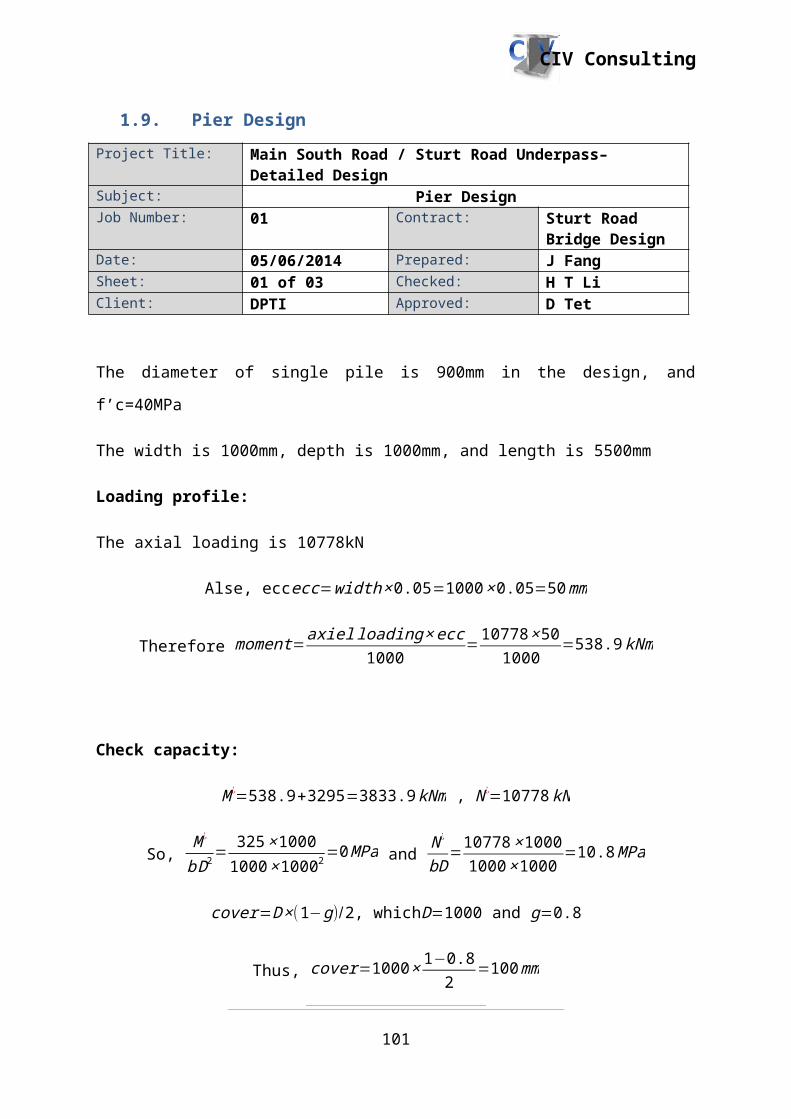
CIV Consulting
Project Title: Main South Road / Sturt Road Underpass– Detailed Design
Subject: Parapet DesignJob Number: 01 Contract: Sturt Road Bridge
DesignDate: 01/06/2014 Prepared: J NgoSheet: 01 of 02 Checked: D TetClient: DPTI Approved: J Rogers
Calculations
Height = 1300mm
Width = 3000mm
Thickness = 300mm (top), 530mm (bottom)
Cover = 40mm (AS 3600 table 4.4/4.10.3.3)
Concrete strength = f’c = 40MPa
Live Load: AS 5100.2 Table 11.2.2
Table 6: Parapet specifications
Barrier Performance
Ultimate longitudinal Outward load (Ft) kN
Ultimate longitudinal Inward load (FL) kN
Vehicle contact length for traverse loads (Lt) and longitudinal loads (LL) m
Ultimate vertical downward load (Fv) kN
Vehicle contact length for vertical loads (Lv) m
Minimum effective height (He) mm
Regular 250 80 1.1 80 5.5 800
Try N12 @ 250 (440mm2)
fsy = 500MPa
Design load = 250 / (1.1 X 1) = 227.27 kN/m2
Designed as two way slab -
Ly/Lx = 3000/1300 = 2.307 > 2
One long edge discontinuous, therefore βx=0.066 and βy=0.028 (Table AS3600 Table
6.10.3.2 (A))
Positive moments at mid-span
M*x = βx x Fd x Lx2
= 0.066 x 227.27 x (1300)2
101

CIV Consulting
= 25.35 kNm
Project Title: Main South Road / Sturt Road Underpass– Detailed Design
Subject: Parapet DesignJob Number: 01 Contract: Sturt Road Bridge
DesignDate: 01/06/2014 Prepared: J NgoSheet: 02 of 02 Checked: D TetClient: DPTI Approved: J Rogers
M*y = βy x Fd x Lx2
= 0.028 x 227.27 x (1300)2
= 10.75 kNm
Negative moments at middle
M*x = 1.33 x 25.35 = 33.7155 kNm
Negative moment at outside
M*x = 0.5 x 10.75 kNm = 5.37727273
Minimum steel requirement
d = 300 – 40 – 12 – 12/2 = 242mm
T = fsy x Ast
T = 440 x 500
T = 220 kN
C = T = fsy x Ast
C = a2 x f’c x b x y x ku x d
a2 = 0.85
y = 1.05 – 0.007 x 40
y = 0.77
ku = (220 x 10^3)/ (0.85 x 40 x 1300 x 0.77 x 242)
ku = 0.0267 < 0.36 OK ductility
Mu = C x (d – 0.5 x y x ku x d)
Mu = 220 x 103 (242 – ½(0.77 x 0.06 x 242)
Mu = 52.69 kNm > (33.72/0.8)=42.15 OK
Adopt N12 @ 250
102

CIV Consulting
1.12.2. Pier Crash Barrier
Following the design of the parapet, the barriers under the bridge will have the same profile
from AS 5100.1 figure 10.6.1 with altered dimensions and have the same capability to be
replaced. The height required for the barriers is 1.4m according to AS 5100.1 Table A3 where
the minimum effective height for barriers of special performance levels should be 1.4m. The
barrier performance level is special to prevent damage to the piers and contain heavy vehicles
on Main South road, which is an arterial road. Being a special performance design, the load
case is taken from AS 5100.2 Table A2. The barriers need to be placed along the underpass
of South Road and encase the piers along the median strip. The amount of barriers required
will be 177 along the median strip with 29 to surround the piers. The crash barriers can be hit
from both sides and will need doubled reinforcement rather than reinforcement along the
middle. The designs will vary slightly to follow the curving slope of the underpass but still
maintain structural integrity.
103

CIV Consulting
Project Title: Main South Road / Sturt Road Underpass– Detailed Design
Subject: Crash Barrier DesignJob Number: 01 Contract: Sturt Road Bridge
DesignDate: 01/06/2014 Prepared: J NgoSheet: 01 of 02 Checked: D TetClient: DPTI Approved: J Rogers
Design calculation
Height = 1400mm
Width = 3000mm
Thickness = 300mm (top), 790mm (bottom)
Cover = 40mm (AS 3600 table 4.4/4.10.3.3)
Concrete strength = f’c = 40MPa
Live Load: AS 5100.2 Table A2
Table 7: Barrier specifications
Barrier Performance
Ultimate longitudinal Outward load (Ft) kN
Ultimate longitudinal Inward load (FL) kN
Vehicle contact length for traverse loads (Lt) and longitudinal loads (LL) m
Ultimate vertical downward load (Fv) kN
Vehicle contact length for vertical loads (Lv) m
Minimum effective height (He) mm
Special test level 6 (36t articulated tanker)
750 250 2.4 350 12 1400
Try N16 @ 200 (1000mm2)
fsy = 500MPa
Design load = 750 / (1.1 X 1) = 227.27 kN/m2
Designed as two way slab -
Ly/Lx = 3000/1400 = 2.14 > 2
One long edge discontinuous, therefore βx=0.066 and βy=0.028 (Table AS3600 Table
6.10.3.2 (A))
Positive moments at mid-span
M*x = βx x Fd x Lx2
104

CIV Consulting
Project Title: Main South Road / Sturt Road Underpass– Detailed Design
Subject: Crash Barrier DesignJob Number: 01 Contract: Sturt Road Bridge
DesignDate: 01/06/2014 Prepared: J NgoSheet: 02 of 02 Checked: D TetClient: DPTI Approved: J Rogers
= 0.066 x 312.5 x (1400)2
= 40.43 kNm
M*y = βy x Fd x Lx2
= 0.028 x 312.5 x (1400)2
= 17.15 kNm
Negative moments at middle
M*x = 1.33 x 40.43 = 53.77 kNm
Negative moment at outside
M*x = 0.5 x 17.15 kNm = 8.58 kNm
Minimum steel requirement
d = 300 – 40 – 16 – 16/2 = 236 mm
T = fsy x Ast
T = 1000 x 500
T = 500 kN
C = T = fsy x Ast
C = a2 x f’c x b x y x ku x d
a2 = 0.85
y = 1.05 – 0.007 x 40
y = 0.77
ku = (500 x 10^3)/ (0.85 x 40 x 1300 x 0.77 x 236)
ku = 0.062251 < 0.36 OK ductility
Mu = C x (d – 0.5 x y x ku x d)
Mu = 500 x 103 (236 – ½(0.77 x 0.06 x 236)
Mu = 115.2 kNm > (33.72/0.8)=42.15 OK
Adopt N16 @ 200
105

CIV Consulting
1.13. Bearing design
A bearing for a bridge is used in order to sit between the Super T and the headstock to
counteract movement of the bridge that may occur. A bearing can absorb any movement of
the bridge structure itself. This is an item that can be sourced from a company and doesn’t
need to be designed. Due to the cross fall of the road which is 4%, there needs to be a design
for compensation of cross fall, as stated by the Department of Planning, Transport and
Infrastructure’s standard design of structures. In order to compensate for this a tapered plate
is to be proved which matches the cross fall of the road, that is then placed between the
Super-T and the bearing
In order to choose a sufficient bearing for the structure, the main criteria would be choosing a
bearing and size that will withstand the loading and meet the ratings criteria. There are two
types of bearings that can be used from the manufacturer Granor, pot bearing or elastomeric
bearing. Each of these types of bearings have been designed in accordance to AS5100.4. An
elastomeric bearing has been chosen due to its familiarity to companies, as it is commonly
used in bridge design.
Figure 19: Typical Elastomeric bearing from Granor
This type of bearing is made out of high quality elastomers with internal layered sheets of
steel reinforcement. J Series rectangular 600x450 elastomeric bearing has been adopted. The
figure below shows the ratings and specifications of the bearing.
106

CIV Consulting
Table 8: Specification of chosen bearing
Elastomeric Bearing
Overall height (mm)
Rated load at max rotation (kN)
Net Weight (kg)
Max deflection (mm)
Part Number
Series J600x400mmRectangular
86 At max shear
At zero shear
67 33 GJE-03
1676 2088
1.14. Summary
Through the use of the analytical program SPACEGASS, our team has been able to get
values in order to design the components of the bridge. Each section of the report has
gone through the analysis that is required in order to made the bridge safety as well as
satisfying the goals of the project. From the analysis or the Australian Standard of Codes,
all the components have been design according to it all, meaning that the underpass will
be safe and has been designed with due care.
107
CIV Consulting
1.15. References
Granor Rubber and Engineering, no date available, Elastomeric Bearings, <
http://www.granor.com.au/uploads//products/elastomericbearings/Granor_Elastomeric_L
aminated_Bearings.pdf>
Loo, Y.C, Chowdhury, S.H 2013, Reinforced and Prestressed Concrete Second Edition,
Cambridge University Press, New York
Merretz W., Smith G., 1997, Standarisation of and Detailing for Super T Bridge Girders,
Structural Concrete Industries, no date available, viewed 30th May 2014, <
http://www.sciaust.com.au/pdfs/supertstandards.pdf>
Warner R., Faulkes K., Foster S., 2013, Prestressed Concrete 3rd Edition, Pearson
Australia, New South Wales
108


