32
MAINTENANCE AND REPAIR MANUAL R 5 Series Models 0160, 0250, 0400, 0502, 0630 B Series Single Stage Rotary Vane Vacuum Pumps

MAINTENANCEAND
REPAIR MANUAL
R 5 SeriesModels 0160, 0250, 0400, 0502, 0630 B Series
Single Stage Rotary Vane Vacuum Pumps

Page
GENERAL 2
Identification 2
1.0 INSTALLATION 21.1 Oil Filling 2
2.0 OPERATION 22.1 Start-up 22.2 Oil Level Float Valve (newer models) 32.3 Gas Ballast 32.4 Water-Cooled Pumps (optional) 32.5 Oxygen Service Pumps 3
3.0 ROUTINE MAINTENANCE 43.1 Pump Oil 43.1.1 Oil Level 43.1.2 Oil Type and Quantity 43.1.3 Oil and Filter Change 43.1.4 Oil Flushing Procedure 53.2 Automotive-Type Oil Filter 53.3 Exhaust Filter 63.4 Vacuum Inlet Filter 63.5 Routine Maintenance Schedule 63.6 Overhaul Kit/Filter 7
4.0 DISASSEMBLY 74.1 Necessary Tools 74.2 Complete Disassembly 74.3 Disassembly of Pump Module 8
We reserve the right to change the product at any time without any form of notification. The information in this pub-lication is accurate to the best of our ability at the time of printing. Busch, Inc. will not be responsible for errorsencountered when attempting to perform tasks outlined in this publication which is copyright protected.
TABLE OF CONTENTS
1
Page
5.0 CLEANING PROCEDURE 9
6.0 PREPARATION FOR ASSEMBLY 96.1 Endplate Preparation 96.2 Exhaust Box Preparation 9
7.0 ASSEMBLY 97.1 Exhaust Valves 97.2 Bearings, Bearing Sleeves, Shaft Seals 107.3 Pump Module for Regular Overhaul 117.4 Pump Assembly 14
8.0 CHANGING FROM RA TO RC MODEL 158.1 Differences Between RA and RC Pumps 15
9.0 OIL LEVEL SWITCH INSTALLATION 15
10.0 TROUBLESHOOTING 16
11.0 LIMITED STANDARD WARRANTY 20
Technical Data and Clearances Chart 21Illustration of R 5 0160 Vacuum Pump 22Parts List for R 5 0160 23Illustration of R 5 0400 Vacuum Pump 24Parts List for R 5 0400 25Illustration of R 5 0502/0630 Vacuum Pump 26Parts List for R 5 0502/0630 27Busch Factory Service Centers 29
GENERAL
Identification
For model identification, see the nameplate mounted onthe side of the exhaust box.
This manual is written to cover RA and RC versions ofmodels 0160, 0250, 0400, 0502 and 0630 with a "B"appearing as the seventh character in the model typenumber stamped into the nameplate. For example, itwould appear as follows:
RAXXXX-BXXX-XXXX
When ordering parts, it is helpful to include the identifi-cation code stamped into the side of the cylinder as wellas the serial number from the nameplate.
All reference (Ref. XXX) numbers listed in the text andon illustrations throughout this manual are related to thedrawings and parts list shown later in this publication.
This manual is designed to help optimize pump per-formance and reduce downtime through proper mainte-nance. Instructions are given for complete disassemblyand assembly.
A separate Installation and Operation manual is provid-ed with each new pump from the factory. Refer to it forgeneral operation and installation guidelines. Pleasecontact the factory if an additional copy is needed.
1.0 INSTALLATION
1.1 Oil Filling
The pump is shipped without oil. After level installation,and after correct rotation has been established, fill thepump with the recommended vacuum oil through the oilfilling port (Ref. 88), observing the "MAX" and "MIN"position at the oil sight glass (Ref. 83). On pumps withtwo sight glasses, fill the top glass up to the 3/4 mark.Non-detergent oil should be used. Do not usedetergent motor oil as additives in detergent oil willplug exhaust filter elements and shorten their life.
2
It is recommended that Busch R500 Series oil be usedto receive the best performance from your vacuumequipment. R500 Series oil is a high quality vacuum oilthat will give longer running time between oil changes,will provide better lubrication at high operating temper-atures, and will prolong the life of exhaust filter ele-ments. This oil can be obtained directly from Busch,Inc. in Virginia Beach, Virginia.
The strict use of Busch oils and parts from the day ofpurchase can extend the Limited Standard Warranty tothree years. Contact Busch, Inc. in Virginia Beach,Virginia for details.
For general applications, use R530 in all models cov-ered by this manual. Use R590 or R570 in pumps thatare operated in high ambient temperatures (above90°F) or high operating pressure when the oil car-bonizes (turns black) before the change interval.Contact the factory for recommendations when usingother oils.
The TECHNICAL DATA chart on page 21 gives theapproximate quantities of oil required for each pump.The oil capacity chart should only be used as a guide,since oil capacity may be slightly lower, depending onwhether the pump was filled previously, and whether allcomponents such as oil filter, oil lines, etc., wereallowed to completely drain. Use only the sight glassreading for proper level. Never overfill!
Replace the oil fill plug (Ref. 88), making sure that thegasket (Ref. 89) is in place and properly seated andsecured. Some pumps are equipped with an exhaustpressure gauge as an integral part of the oil fill plug.
2.0 OPERATION
2.1 Start-up
Check rotation of the motor to insure it is rotating in thecorrect direction.
Fill the pump with oil as described in Section 1.1 - OilFilling.
Start the pump and immediately close the inlet. Run thepump for a few minutes before checking the oil levelagain. With the pump shut off, the oil level should bevisible in the oil sight glass (Ref. 83), between the "MIN"and "MAX" mark.
On pumps with two sight glasses, with the pump shutoff, the oil level should be visible in the upper oil sightglass, between the "MIN" and "MAX" mark.
Add oil, if necessary, but only add it when the pump hasbeen shut off and the circulating oil has had sufficienttime to return to the oil sump.
WARNING: Do not use hydrocarbon oils inpumps on oxygen service. See Section 2.5- Oxygen Service Pumps.
WARNING: Keep the oil fill plug tight aspressure in the exhaust box could causebodily injury if the plug is blown out. Do notfill/add the pump with oil through theexhaust/inlet ports as there is danger ofbreaking the vanes!

3
On R 5 (Standard) RC model pumps, the collected oil isdrawn continuously during operation of the vacuumpump to the inlet flange (Ref. 260) via the oil return line(Ref. 290). The oil return line is connected directly tothe area of the exhaust box, downstream of the exhaustfilter, which is at atmospheric pressure. RC modelpumps can run continuously without having to shutthem off for the oil to drain back.
2.2 Oil Level Float Valve (newer models)
Older models of the RA 0160, 0250, 0400 and 0630 hadto be shut off every 8 hours of operation to allow oil todrain back to the oil sump via an oil check valve. Newermodel RA 0400, RA 0502 and 0630 pumps have a floatvalve mechanism (Ref. 585) added to the outside of theexhaust box where the two oil return valves are located.This mechanism contains a float valve housed in a steelbox that is mounted to the exhaust box. An oil returnline runs from the steel box to the inlet of the pump. Asthe oil drips off of the exhaust filters and collects in thefloat box the float rises opening the valve and allowingthe vacuum (suction) to draw the accumulated oilthrough the oil return line back into the inlet of thepump. As the oil level drops in the float box the valvecloses "blanking off" the oil return line. The idea is thatthe oil return line is always full of oil which prevents aloss of vacuum allowing the pump to achieve ultimatepressure and run continuously at the same time.
Newer 0400/0502/0630 pumps are configured with thefloat valve, but an existing pump in the field can bemodified to have this oil float valve assembly by order-ing a float valve kit Busch P/N 0946.529.715. Contactthe Service Department of Busch, Inc. in Virginia Beachis you wish to add this feature to an older pump in thefield or if you are unsure whether you pump has thisfeature already.
2.3 Gas Ballast
This series of RA pumps are equipped with anadjustable gas ballast valve. The gas ballast valve(Ref. 440) is located between the inlet port and theexhaust box.
The adjustable gas ballast valve should normally be leftopen. Its primary function is to prevent water vaporfrom condensing in the pump. Condensation causesemulsification of the oil, loss of lubricity, and possiblerotor seizure.
2.4 Water-Cooled Pumps (optional)
Water-cooled pumps are cooled by circulating the oilthrough a shell-and-tube type heat exchanger (see Fig.1). The circulation of the cooling water through thetubes is thermostatically controlled. The flow rate of thecooling water is controlled by a thermostatically activat-ed valve.
The thermostatic valve can be manually opened byinserting a screwdriver under each side of the springguide and prying the spring and guide upward awayfrom the valve body.
Refer to your Installation and Operation manual forinstructions on adjustment and operation of this valve,or call Busch, Inc. in Virginia Beach, VA. for help.
2.5 Oxygen Service Pumps
These pumps have been manufactured, solventwashed (to remove organic contaminants) and assem-bled according to the latest technical standards andsafety regulations. If this pump is not installed properlyor not used as directed, a dangerous situation or dam-age might occur.
For overhaul/repair of oxygen service pumps,Busch Inc. strongly recommends that all major repairoperations be conducted at the factory. Improperhandling of repairs could result in extremedanger to personnel operating the pump.
Note: Pumps returned to Busch, Inc. for repair or serv-ice must be decontaminated and free of harmful or toxicmaterial prior to shipment. Certified documentation ofdecontamination must be provided prior to the pump's
WARNING: This pump is filled with a specialoperating fluid. Do not use any other typeof fluid, oil and/or grease. Use one of thefollowing:
• Fomblin LC 250• Tyreno Fluid 12/25V (perfluorinated polyether)• KRYTOX ® Vacuum pump fluid by Du Pont Company
If you have any questions, please phone ourCustomer Service Department for more information.
Thermostaticvalve
Heatexchanger
Fig. 1 - Water-cooled Pump

4
arrival at Busch. Pumps arriving without certificationwill, at Busch Inc.'s discretion, be refused shipment orwill be re-routed to a commercial decontamination facil-ity. All ensuing decontamination costs will be borne bythe shipper.
3.0 ROUTINE MAINTENANCE
R 5 Series pumps require very little routine mainte-nance; however, to insure optimum pump performance,the following steps are recommended.
3.1 Pump Oil
3.1.1 Oil Level
With the pump installed relatively level, make sure thatthere is sufficient clean oil in the pump. The oil levelshould be observed on a daily basis and/or after 8hours of operation and should be replenished if it dropsbelow the 1/4 mark on the oil sight glass on pumps withone sight glass or below the 1/4 mark on the upper oilsight glass on pumps with two sight glasses.
On RA Series pumps which do not have an oil level floatvalve, you must first shut the pump off in order to let theoil flow back into the oil sump prior to checking the sightglass. Allow sufficient time for the oil to drain back intothe sump on the pump prior to adding oil, or overfillingcould result.
Oil level readings should be done only when the pumpis turned off. Oil can be added to the oil fill port (Ref.88) if the pump is shut off and the circulating oil has suf-ficient time to return to the oil sump. The oil mightappear to be foamy, which is a normal phenomenonwith aerated oil.
Under normal circumstances, it should not be neces-sary to add or drain oil from the pump between recom-mended oil changes.
A significant drop in oil level means there is an oil leakor that an exhaust filter is broken which would causethe pump to smoke excessively. It is normal for the oilto be foamy and light in color in an operating pump.However, if the oil is milky colored, it is an indicationthat water is present in the oil. Normally, by operatingthe pump for an extended period, with the inlet suctionblanked off and the gas ballast open on RA pumps, thewater will be purged from the oil. If the oil is dark col-
ored, it is contaminated or carbonized and must bechanged. Depending on the severity of the contamina-tion, a thorough flushing may be needed. See Section3.1.4 for the flushing procedure.
3.1.2 Oil Type and Quantity
See Section 1.1 - Oil Filling for details on oil type andquantity.
3.1.3 Oil and Filter Change
Oil life is dependent upon the conditions to which it isexposed. A clean, dry air stream and an oil operatingtemperature under 210°F are ideal conditions. Whenusing R530 (hydrocarbon oil), it is recommended thatoil changes are made every three (3) to four (4) monthsor 500 to 750 hours of operation, or as necessary if highheat is contaminating the oil. The use of Busch R570or R590 synthetic oils could extend the operating hoursbetween oil changes under ideal conditions. Oil sam-ples should be taken regularly when exceeding the 500-750 hour recommendation.
Excessive Heat
When the pump is subjected to operating conditionsthat will cause the oil to be heated above 235°F, the oilwill carbonize and become contaminated after a rela-tively low number of operating hours. The higher thetemperature, the quicker the oil becomes contaminated.If the oil temperature is too severe, Busch R570 orR590 synthetic oil should be used to withstand the ele-vated temperatures. If synthetic oil is used, the pumpshould be flushed with Busch R568 oil as outlined inSection 3.1.4. Auxiliary oil cooling is the most practicalapproach to a severe heating problem.
Contaminated Air Stream
When the air stream contains a solid and/or liquid thatcan contaminate the oil, it must be changed more often.If the air stream contains a small percentage of con-taminates and/or they are slightly aggressive (mildacids, etc.), synthetic oil, such as Busch R570, willresist breakdown better than the standard Busch R530.The solution is to install a filter or knock-out pot to keepthe contaminates out of the pump.
Process air streams with a large percentage of contam-
CAUTION: When changing the oil and fil-ters, it may be necessary to flush the pumpto remove any build-up of degraded oil fromthe sumps, oil lines, radiators, etc., toensure proper oil flow through the pump.Reduced oil flow, especially through radia-tors and cooling coils, can cause mechani-cal damage or extreme overheating, whichcould cause the oil vapors to ignite.
CAUTION: Insufficient oil quantity in thepump has the potential, under certain con-ditions, to lead to self-ignition of theremaining oil in the pump
CAUTION: Do not add oil while the pump isrunning since hot oil vapor may escapethrough the oil fill port.
5
inates and/or more than slightly aggressive contami-nates must use a once-through-sealant or dry-typepump.
Oil change intervals can only be established by experi-ence with the pump operating in the actual conditions(see previous paragraph for some of the conditions).Develop the oil change interval by periodically checkingan oil sample removed from the pump. When the oilsample has become dark in color (from solids and car-bonized particles) or is milky looking (from solids), it istime to discard it. As mentioned before, a thoroughflushing may be needed.
3.1.4 Oil Flushing Procedure
Flushing is needed under certain conditions. Somepumps will be beyond flushing and will need to be over-hauled.
To help determine if flushing is needed, observe thecondition of the oil as it is drained from the pump. Is itblack and tar like or contaminated in any way? Was thepump noisy, overheating, or was the motor overloadshutting the pump off? How old is the pump and whenwas the last time the oil was changed?
If the above conditions exist or you don't know when thelast oil change was performed further investigation isneeded. Flushing is always required if changing fromone oil type, such as R530, to R570 or R590.
All of the oil will be removed and replaced with theflushing oil (Busch R-568), and eventually that will bereplaced by whatever Busch oil is needed for your par-ticular application. Have enough oil and oil filters onhand for a couple of flushes. The following describesthe steps in the flushing procedure:
Shut the pump off and drain all the oil from the pumpand remove the access plates (Ref. 205) from theexhaust box (Ref. 075). Remove the metal baffle (Ref.078) and take a good look at the internal walls of the oilsump. If the walls are discolored but have no build upof any kind one can proceed with the flushing. If gelledor burnt oil is clinging to the walls this material must bescraped and removed prior to flushing. Proceed byscraping and cleaning as much of the exhaust box aspossible. The more debris that is removed now themore effective the flushing will be later. Re-install themetal baffle, cover and proceed with the flushing. Atthis point one must remember that the oil lines and oilcooler might also be plugged to a point where noamount of flushing will make a difference and a com-plete overhaul will be the only option. Depending onthe severity of the oil contamination flushing may be alast ditch effort.
Drain all of the oil from the pump. The more contami-nated oil you remove now the more effective the oil
flushing will be.
Remove the oil filter (Ref. 100) and install a new one. Itis recommended that you do not change the exhaust fil-ter or filters until after the flushing to prevent contami-nation of any new filters.
Fill the exhaust box with the proper amount of flushingoil (Busch R-568).
If possible run the pump with the inlet closed and off ofthe process. Run the pump for approximately six hours,shut the pump off and drain a small sample of oil into aclear container.
Examine it. If it is clear to amber run the pump foranother six hours and examine it again. If after the firstsix hours it is black drain it and fill again using anothernew oil filter.
If after the second flushing the oil still remains black thepump may have too much contaminated oil in it to flushout properly. There may be residue remaining in thelines and cooler that will not flush out. An overhaul willbe necessary.
If after the second six hour period the oil still remainsclear to amber in color drain it, change the oil filter andfill with the regular oil. At this point also change theexhaust filters.
Run the pump with a fresh charge of the oil to be usedin your application (not R-568), and monitor the operat-ing conditions closely. Check for noise, overheatingand oil condition until a regular oil change schedule canbe established.
Do not let the oil turn black. Change it before it fails. Ifthe oil is kept in good condition the pump will last foryears. If the oil starts to turn black do not hesitate toflush again. Keeping on top of the oil changes will pre-vent costly overhauls.
If you are just switching from one type of oil to anothera single six hour flush is all that is necessary (follow theabove instructions). Remember to change to a newexhaust filter or filters after the flushing and not before.
3.2 Automotive-Type Oil Filter
To replace the automotive-type oil filter (Ref. 100), thepump should have been running for at least 15 minutesso that the oil is warm. Then switch off the pump,remove the oil drain plug (Ref. 95) and drain the oil.With an automotive-type wrench, remove the oil filterand replace it with a new one. Coat the face of the gas-ket (new filter) with oil and hand tighten until the gasketcontacts the base, then tighten two-thirds turn more.Do not over-tighten. If an O-ring is included, discard it.It is not used in this application. When replacing the
6
automotive-type filter, use only a genuine Busch filter.
Note: Make sure to tighten the Busch oil filter secure-ly against the aluminum sealing surface so that leakswill not occur.
3.3 Exhaust Filter
Every nine (9) to twelve (12) months, or as necessary,replace the exhaust filter elements. The service life ofthe exhaust filters varies widely with pump application.It is only necessary to change the filters when the ele-ments become clogged with foreign material or burnedoil. Indications of clogged filters are smoke and oil mistcoming from the pump exhaust, higher than normalmotor current or oil leaking from the gas ballast valveon RA models.
A pressure gauge (Ref. 90) is supplied with your R 5vacuum pump as part of the oil fill plug. This gauge hasa green field and a red field. Pressure within the greenfield would indicate normal pressure. Pressure in thered field (for a continuos period of time) requires animmediate change of the exhaust filter(s).
In order to replace the filter, remove the screws retain-ing the exhaust port cover plate. Pull the housing offthe exhaust box; set it aside. Use a slotted head screwdriver to loosen the exhaust filter retaining spring (Ref.125), then rotate and remove the spring. Pull the filtercartridge (Ref. 120) out of the exhaust box.
To field test an exhaust filter element, remove it fromthe pump, allow it to cool, clean the sealing end (or O-ring end), and use compressed air to blow through the
element. Apply approximately 3 to 6 psi (maximumallowable operating pressure across the filter).
Use a shop rag to seal off the connection between theair hose and the filter. If you can blow through it, theelement is not plugged. If plugged, discard it and installa new one. The filter cannot be cleaned successfully.Visually inspect the filter element for cracks.
Reinstall the filter elements. Make sure the open end ofthe element is properly seated down in its recess in theexhaust box with the O-ring (Ref. 121) correctly posi-tioned. Retain the filter with the spring clip, tighten thetension screw until the filter is secure. Place theexhaust port gasket and cover in position on theexhaust box and retain with the cap screws.
3.4 Vacuum Inlet Filter
If the pump is equipped with a special vacuum inlet fil-ter in applications where powder, dust or grit is present,the filter cartridge should be cleaned on a weekly basis,or as required, depending on the amount of foreign par-ticles to which the pump is exposed.
To clean the inlet filter, unsnap the lid clamps or removethe knobs and lift off the filter lid. Remove cartridge,being careful not to knock any foreign particles presentinside the canister into the pump suction. Clean foreignparticles from the canister with an air hose, and care-fully back flush the filter cartridge with shop air. If the fil-ter cartridge has been subjected to moisture or isextremely dirty, it may need replacement.
3.5 Routine Maintenance Schedule
See the motor manufacturer’s manual for the periodicmotor maintenance.
Daily: Visually check oil level (see 3.1.1).
Weekly: Check oil for contamination (see 3.1.3).Inspect inlet filter (see 3.4).
Every three (3) or four (4) months, 500 to 750hours of operation, or as necessary: See 3.1.3and 1.5. Drain and discard oil from the hot pump.Replace the automotive-type oil filter and refill withfresh oil through the fill plug (see 3.1.2 through 3.1.3and 3.2).
Every nine (9) to twelve (12) months, or asnecessary: Replace exhaust filter elements (see3.3).
CAUTION: On 0400/0502/0630 models, aswitch mounted on the cover side plate ofthe exhaust box is a safety device. Thisswitch is used to shut off the pump in theevent the pump oil chamber is overheated.Wire this normally closed switch into astarter control circuit so that when theswitch reaches the set point, power to thepump is discontinued.
WARNING: Do not inhale through the filteror allow your mouth to come in direct con-tact with the filter.
WARNING: If the gas entering the pump is ahealth hazard, use rubber gloves and allnecessary personal protection equipmentwhen performing the exhaust filter replace-ment operation. Wear safety glasses asexhaust filter retainers can, if not securedcorrectly, slip off and fly out of the exhaustbox.
CAUTION: Excessively contaminated and/orclogged exhaust filters could possibly leadto elevated pump temperatures whichcould, under certain circumstances, causethe lubricating oil to self-ignite.

7
3.6 Overhaul Kit/Filter
An overhaul kit containing a set of gaskets and O-rings,vanes, bearings and bearing sleeves, shaft seals andtaper pins, is available from the factory. Also, a filter kitcontaining oil drain plug, gaskets, automotive-type oilfilter, exhaust filter, and synthetic baffle strainer (whereapplicable), is available from the factory. When order-ing, please specify pump size and model (a 4-digit suf-fix after size), and serial number.
4.0 DISASSEMBLY
All R 5 Series, Single Stage, Rotary Vacuum pumpsshould only be disassembled and reassembled by qual-ified personnel. Caution must be exercised to preventdamage to the pump components.
4.1 Necessary Tools
To disassemble/assemble all the R 5 Series pumps, thefollowing tools are recommended:
Allen Wrench: 2.5mm, 4mm, 6mm, 12mmFilter Wrench: (Strap wrench)Open End Wrench: 10mm, 12mm, 13mm, 15mm,17mm, 19mm, 22mm, 24mm, 27mm, 32mmSocket Wrench with Extension: 10mm, 13mm, 17mm,19mm, 24mmHex Head Nut, Regular Pitch: 6mm, 8mmScrewdriverDrum Plug WrenchRubber MalletGear Puller (Fan and Coupling)Dial Indicator with Magnetic or Clamp-on BaseArbor Press to Install Bearing and Shaft SealsLoctite 242 for Shaft Seal and Bearing InstallationMiscellaneous Feeler Blades 18 inches long: .03mm,.04mm, .06mm, .07mm, .09mm.Shaft Seal Bearing Installation Tool, Shaft SealInstallation Sleeve, and Rotor Pulling Tools (Availablefrom Busch, Inc. in Virginia Beach).
4.2 Complete Disassembly
Shut the pump off and disconnect power supply to themotor. Drain the oil through the oil drain plug (Ref. 95).(See pump illustrations Figures 16, 17 and 18 for partidentifications.) Tilt the pump toward the oil drain plug,allowing it to drain.
Remove the motor (Ref. 400) from the motor mountingbracket (Ref. 300) by removing four hex head capscrews (Ref. 401).
Remove the pump side coupling half (Ref. 310) by loos-ening the set screws. A gear puller will be necessary topull the coupling off the rotor shaft. Extreme care mustbe given to the end of the rotor shaft so that the shaftcenter is not damaged by the gear puller.
Note: "Wood’s" type couplings have a special spacer,one on the motor shaft and one on the pump shaft.Mark these for correct reassembly before removingthem.
Remove the motor mounting bracket (Ref. 300) fromthe cylinder endplate (Ref. 25) by removing three (3)hex head nuts (Ref. 303).
Remove the oil cooling coil (Ref. 240) (not applicable on0502/0630 pumps) by loosening the fittings from theexhaust box and the pump module.
Remove the fan cover (Ref. 340) from the cylinder end-plate (Ref. 26) by removing the three (3) sheet metalscrews (Ref. 341).
Remove the fan (Ref. 321) from the rotor shaft of thepump module by loosening the set screw. On0400/0502/0630 pumps, there is a locking disc (Ref.327) connected to the end of the fan side rotor shaftwhich needs to be removed prior to removing the fan.Remove the fan (Ref. 321) with a gear puller. There isalso a distance ring (Ref. 320) behind the fan thatneeds to be removed (0400/0502/0630 only).
Model 0502/0630 pumps are equipped with a coolingradiator (Pos 241) installed at the fan side of the pump.The following oil fittings need to be loosened (Ref. 221,223, 224). Remove the six hex head cap screws (Ref.357) which will allow the removal of the radiator andradiator side center ring (Ref. 351). It is now possibleto remove the fan guard (Ref. 352), fan (Ref. 321), dis-tance ring (Pos 320), and center ring (on endplate side)(Ref. 350).
On RA pumps, the gas ballast valve (Ref. 440) can nowbe removed from the fan side endplate.
On RC pumps, remove the oil return line (Ref. 290)from the inlet flange (Pos 260) and the exhaust box(Ref. 75). On RA Models, oil non return valve (Ref.275) should be removed and checked.
Loosen and remove all hydraulic fittings connected tothe endplates (Ref. 25/26) and the exhaust box (Ref.75).
Remove the exhaust box cover plate (Ref. 205) whichis located to the right of the oil sight glasses.
WARNING: Shut the pump off. Lock theelectrical panel in the off position to pre-vent the power from accidently being rein-stated during the operation.
WARNING: Do not apply pressure or vacu-um by mouth.
8
With the inside of the exhaust box now visible, theexhaust valve cover plate (Ref. 169) with gasket (on RApumps only) can now be removed by loosening andremoving a hex head nut or a bolt in the center of thecover plate.
If only the exhaust valves (Ref. 159) need to be takenout or replaced, it will not be necessary to separate thepumping module from the exhaust box.
To separate the pump cylinder (Ref. 1) from the exhaustbox (Ref. 75), remove the hex head cap screws (Ref.186) with lockwashers (Ref. 187) from within theexhaust box. On 0160/0250 models, there are internaland external nuts and screws that have to be removed.
The exhaust box can now be separated from the pumpmodule. The gasket (Ref. 185) can be removed andreplaced, if necessary.
The exhaust valves can now be removed by looseningthe slotted machine screw with a large screwdriver (forplastic valves) or with a 10mm socket wrench (for allsteel valves).
The sheet metal piece (Ref. 78), which is locatedtowards the bottom of the exhaust box, and the steeldernister (Ref. 79), which is located towards the fill pluginside the exhaust box, can now be removed for clean-ing or replacement. The sheet metal piece will requiresome bending to remove it.
The inlet housing (Ref. 260) can be removed from themodule by removing four hex head cap screws (Ref.265). The inlet housing comes in two pieces. The inletscreen should be cleaned or replaced. The anti-suck-back valve (Ref. 251-255) needs to be looked at toassure proper function. Check to see that the valveplate (Ref. 251) moves freely and seats properly. Thespring (Ref. 254) should be adjusted so it holds thevalve plate slightly ajar. All O-rings and/or gasketsshould be replaced, if necessary, before reassembling.
To check exhaust filters (Ref. 120), it will be necessaryto remove the exhaust end cover plate (Ref. 140) byremoving either the hex head cap screws (Ref. 142) forthe 0160 model or the socket head cap screws (Ref.142) for the 0400/0502/0630 models. The syntheticbaffle (Ref. 130) needs to be removed and replaced, ifnecessary.
Remove filter springs (Ref. 125) by loosening pan headmachine screw (Ref. 126) with a screwdriver. Push thefilter spring with a large screwdriver from the frame so
that the spring assembly pops out. Slide the exhaust fil-ters (Ref. 120) with O-rings (Ref. 121) out of theexhaust box. Examine filter elements to see if they areclogged. See Section 3.3 for details.
To replace the automotive type oil filter (Ref. 100), thepump should have been running for at least 15 minutes,so that the oil is warm. Then turn the pump off, removethe oil drain plug (Ref. 95), and drain the oil. With anautomotive type filter wrench (strap wrench), removethe oil filter, and replace with a new one. Coat face ofgasket on new filter with oil and hand tighten until gas-ket contacts base, then tighten two-thirds turn more.Do not overtighten. Use only a genuine Busch filter.
4.3 Disassembly of Pump Module
Set module on a table or vise with the exhaust port fac-ing down and the inlet facing you (see Fig. 8 and 9).
Remove threaded taper pin (Ref. 60) by placing awasher or lockwasher over thread and then a 6mm or8mm nut against the washer/lockwasher to loosen thetaper pins. Use of a lockwasher acting as a spring willease removal. In essence, the washer/lockwasher isused as a spacer and the 6mm or 8mm nut is used asa jackscrew to draw the pin out.
Remove the hex head cap screws (Ref. 53)so the end-plate may be separated from the pump cylinder. Becareful not to damage the sealing faces, O-ring (Ref.50) or paper gaskets between the endplates. If the end-plates do not come off easily, tap gently with a rubbermallet or soft hammer, or remove all threaded studs(Ref. 4) from the cylinder. On older pumps with gasketsbetween endplates and cylinder, take note how many,and the thickness of the gaskets used on each side ofthe cylinder. The same quantity and thickness can beused upon assembly if no major parts were replaced ormachined.
The rotor (Ref. 15) and vanes (Ref. 22) can now beremoved from the cylinder (Ref. 1). Care must be takenwhen removing the rotor to prevent damaging the rotoror the cylinder.
Inspect vane slots for wear. The slot walls should beparallel to each other. If the slots are worn in a V pat-tern the rotor should be replaced. Insert a new vane inthe slot and measure the gap between the vane and theslot wall. If the gap exceeds .3mm replace the rotor.Check the rotor for trueness before reassembly. Thiscan be done by chucking the rotor in a lathe and check-ing the run-out or eccentricity (T.I.R.). The maximumallowable run-out is 0.02mm (0.001”). See theClearances Chart on page 21.
The bearings (Ref. 30) and shaft seals (Ref. 35) can beremoved from the endplates via an arbor press using abearing and shaft seal removal tool (see Fig. 2 and 3).
WARNING: Wear safety glasses whenremoving or installing the exhaust filtersprings. Be prepared for the possibility ofthe spring suddenly releasing if it is not inthe spring pocket correctly.
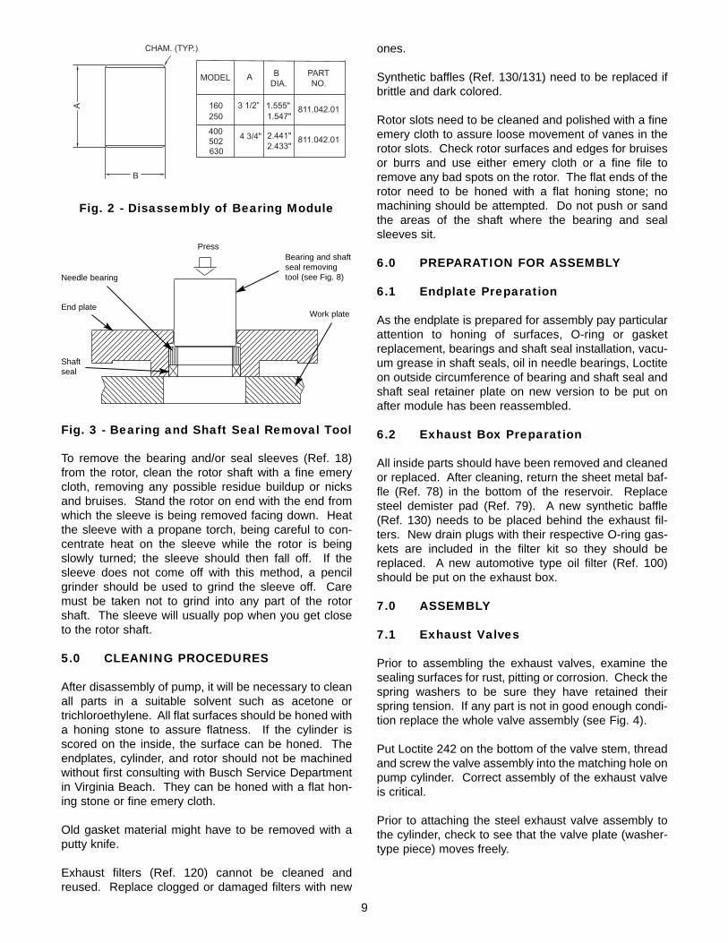
To remove the bearing and/or seal sleeves (Ref. 18)from the rotor, clean the rotor shaft with a fine emerycloth, removing any possible residue buildup or nicksand bruises. Stand the rotor on end with the end fromwhich the sleeve is being removed facing down. Heatthe sleeve with a propane torch, being careful to con-centrate heat on the sleeve while the rotor is beingslowly turned; the sleeve should then fall off. If thesleeve does not come off with this method, a pencilgrinder should be used to grind the sleeve off. Caremust be taken not to grind into any part of the rotorshaft. The sleeve will usually pop when you get closeto the rotor shaft.
5.0 CLEANING PROCEDURES
After disassembly of pump, it will be necessary to cleanall parts in a suitable solvent such as acetone ortrichloroethylene. All flat surfaces should be honed witha honing stone to assure flatness. If the cylinder isscored on the inside, the surface can be honed. Theendplates, cylinder, and rotor should not be machinedwithout first consulting with Busch Service Departmentin Virginia Beach. They can be honed with a flat hon-ing stone or fine emery cloth.
Old gasket material might have to be removed with aputty knife.
Exhaust filters (Ref. 120) cannot be cleaned andreused. Replace clogged or damaged filters with new
ones.
Synthetic baffles (Ref. 130/131) need to be replaced ifbrittle and dark colored.
Rotor slots need to be cleaned and polished with a fineemery cloth to assure loose movement of vanes in therotor slots. Check rotor surfaces and edges for bruisesor burrs and use either emery cloth or a fine file toremove any bad spots on the rotor. The flat ends of therotor need to be honed with a flat honing stone; nomachining should be attempted. Do not push or sandthe areas of the shaft where the bearing and sealsleeves sit.
6.0 PREPARATION FOR ASSEMBLY
6.1 Endplate Preparation
As the endplate is prepared for assembly pay particularattention to honing of surfaces, O-ring or gasketreplacement, bearings and shaft seal installation, vacu-um grease in shaft seals, oil in needle bearings, Loctiteon outside circumference of bearing and shaft seal andshaft seal retainer plate on new version to be put onafter module has been reassembled.
6.2 Exhaust Box Preparation
All inside parts should have been removed and cleanedor replaced. After cleaning, return the sheet metal baf-fle (Ref. 78) in the bottom of the reservoir. Replacesteel demister pad (Ref. 79). A new synthetic baffle(Ref. 130) needs to be placed behind the exhaust fil-ters. New drain plugs with their respective O-ring gas-kets are included in the filter kit so they should bereplaced. A new automotive type oil filter (Ref. 100)should be put on the exhaust box.
7.0 ASSEMBLY
7.1 Exhaust Valves
Prior to assembling the exhaust valves, examine thesealing surfaces for rust, pitting or corrosion. Check thespring washers to be sure they have retained theirspring tension. If any part is not in good enough condi-tion replace the whole valve assembly (see Fig. 4).
Put Loctite 242 on the bottom of the valve stem, threadand screw the valve assembly into the matching hole onpump cylinder. Correct assembly of the exhaust valveis critical.
Prior to attaching the steel exhaust valve assembly tothe cylinder, check to see that the valve plate (washer-type piece) moves freely.
����������
�
�� ���
������
������
���
� ����� � �
���
������
������ ������
����������
����������������
������������
Fig. 2 - Disassembly of Bearing Module
Fig. 3 - Bearing and Shaft Seal Removal Tool
Press
Needle bearing
Shaftseal
Work plateEnd plate
Bearing and shaftseal removingtool (see Fig. 8)
9
7.2 Bearings, Bearing Sleeves, Shaft Seals
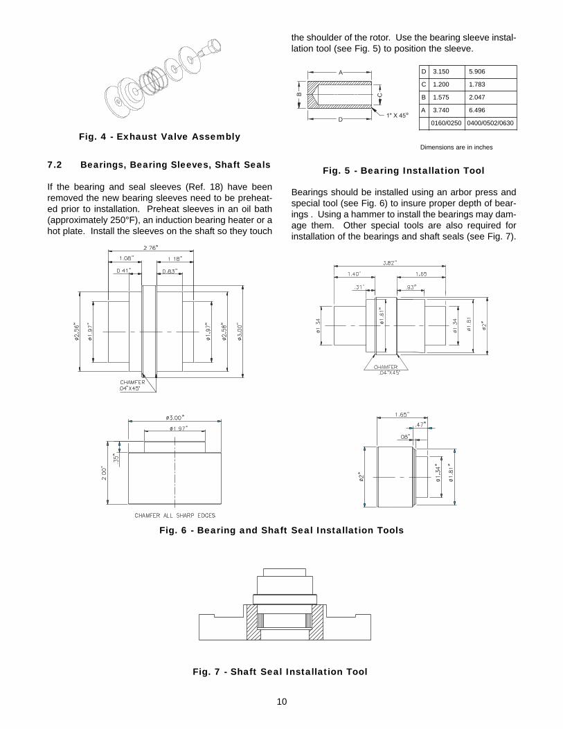
If the bearing and seal sleeves (Ref. 18) have beenremoved the new bearing sleeves need to be preheat-ed prior to installation. Preheat sleeves in an oil bath(approximately 250°F), an induction bearing heater or ahot plate. Install the sleeves on the shaft so they touch
the shoulder of the rotor. Use the bearing sleeve instal-lation tool (see Fig. 5) to position the sleeve.
Bearings should be installed using an arbor press andspecial tool (see Fig. 6) to insure proper depth of bear-ings . Using a hammer to install the bearings may dam-age them. Other special tools are also required forinstallation of the bearings and shaft seals (see Fig. 7).
�
�
�
�
��� ����
D 3.150 5.906
C 1.200 1.783
B 1.575 2.047
A 3.740 6.496
0160/0250 0400/0502/0630
Dimensions are in inches
Fig. 5 - Bearing Installation Tool
Fig. 6 - Bearing and Shaft Seal Installation Tools
Fig. 7 - Shaft Seal Installation Tool
10
Fig. 4 - Exhaust Valve Assembly
The shaft seal (Ref. 35) should be installed with thespring side towards the bearing. Verify that the shaftseal is equipped with a spring on the inner lip. Prior toinstalling the shaft seal in the endplate, put a drop ofLoctite No. 242 on the outside circumference of theshaft seal. Be sure that the correct seals (Buna orViton) are installed.
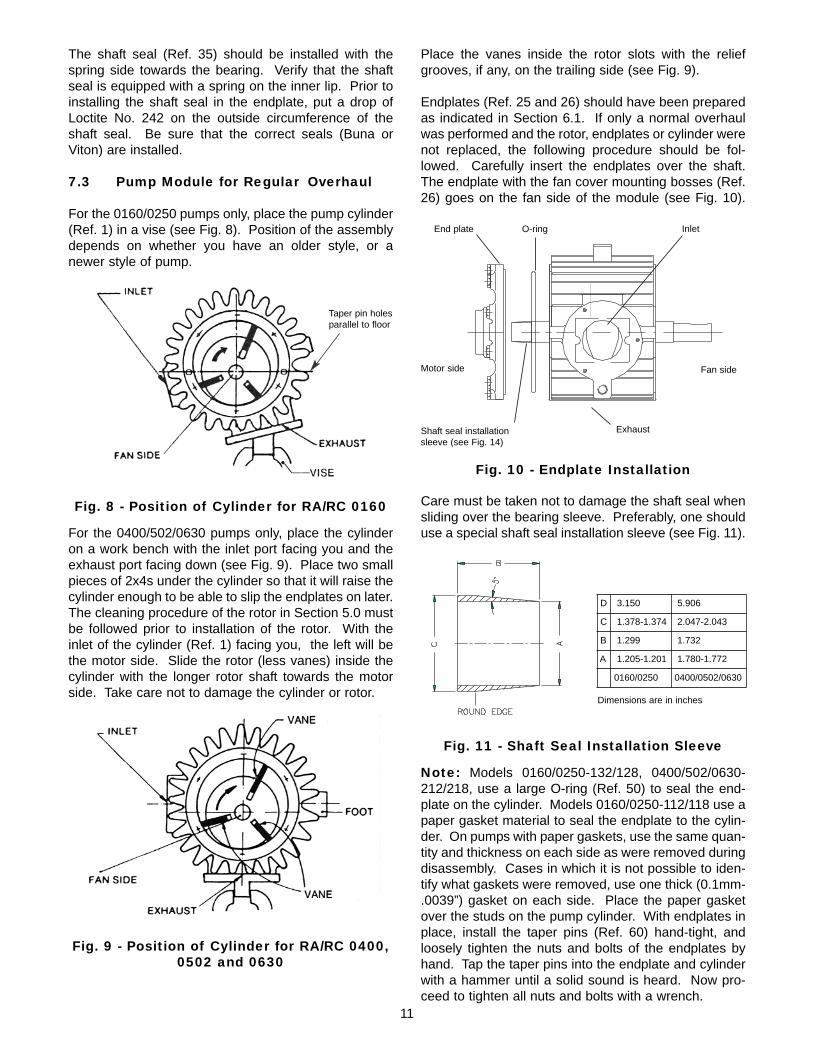
7.3 Pump Module for Regular Overhaul
For the 0160/0250 pumps only, place the pump cylinder(Ref. 1) in a vise (see Fig. 8). Position of the assemblydepends on whether you have an older style, or anewer style of pump.
For the 0400/502/0630 pumps only, place the cylinderon a work bench with the inlet port facing you and theexhaust port facing down (see Fig. 9). Place two smallpieces of 2x4s under the cylinder so that it will raise thecylinder enough to be able to slip the endplates on later.The cleaning procedure of the rotor in Section 5.0 mustbe followed prior to installation of the rotor. With theinlet of the cylinder (Ref. 1) facing you, the left will bethe motor side. Slide the rotor (less vanes) inside thecylinder with the longer rotor shaft towards the motorside. Take care not to damage the cylinder or rotor.
Place the vanes inside the rotor slots with the reliefgrooves, if any, on the trailing side (see Fig. 9).
Endplates (Ref. 25 and 26) should have been preparedas indicated in Section 6.1. If only a normal overhaulwas performed and the rotor, endplates or cylinder werenot replaced, the following procedure should be fol-lowed. Carefully insert the endplates over the shaft.The endplate with the fan cover mounting bosses (Ref.26) goes on the fan side of the module (see Fig. 10).
Care must be taken not to damage the shaft seal whensliding over the bearing sleeve. Preferably, one shoulduse a special shaft seal installation sleeve (see Fig. 11).
Note: Models 0160/0250-132/128, 0400/502/0630-212/218, use a large O-ring (Ref. 50) to seal the end-plate on the cylinder. Models 0160/0250-112/118 use apaper gasket material to seal the endplate to the cylin-der. On pumps with paper gaskets, use the same quan-tity and thickness on each side as were removed duringdisassembly. Cases in which it is not possible to iden-tify what gaskets were removed, use one thick (0.1mm-.0039”) gasket on each side. Place the paper gasketover the studs on the pump cylinder. With endplates inplace, install the taper pins (Ref. 60) hand-tight, andloosely tighten the nuts and bolts of the endplates byhand. Tap the taper pins into the endplate and cylinderwith a hammer until a solid sound is heard. Now pro-ceed to tighten all nuts and bolts with a wrench.
Fig. 8 - Position of Cylinder for RA/RC 0160
Fig. 9 - Position of Cylinder for RA/RC 0400,0502 and 0630
Motor side
O-ring
Fan side
End plate Inlet
Exhaust
Fig. 10 - Endplate Installation
D 3.150 5.906
C 1.378-1.374 2.047-2.043
B 1.299 1.732
A 1.205-1.201 1.780-1.772
0160/0250 0400/0502/0630
Dimensions are in inches
Fig. 11 - Shaft Seal Installation Sleeve
Shaft seal installationsleeve (see Fig. 14)
11
o o
Taper pin holesparallel to floor

It will now be necessary to check for proper axial andradial clearances. The axial clearance is checked byinstalling a dial indicator on one end of the shaft (seeFig. 12). Pull the opposite end of the shaft as far as itwill pull away from the dial indicator. Set the indicatorat zero (0). Push the shaft toward the dial indicator asfar as it will push. The reading on the dial indicator willbe your axial clearance. The recommended axial clear-ances are shown in the chart located near the back ofthis manual (see page 21).
Check the radial clearances (see Fig. 13) by inserting afeeler gauge blade into the inlet of the pump in thedirection of the smallest clearance between rotor andcylinder. Check the radial clearance in three (3) loca-tions along the rotor. The recommended radial clear-ances are shown in the chart located near the back ofthis manual (see page 21).
If clearances check out okay, one may proceed toassemble the pump. If clearances do not correspond towhat they should be or if a new rotor, endplates or cylin-der were used, one will have to use the procedure men-tioned for Assembly of Module if the Rotor,Endplates or Cylinder had to be replaced.
Note: On Models 0160/0250-112/118, the axial clear-ances can be changed by either placing another papergasket between the cylinder and endplate to increasethe axial clearance or using a thinner gasket todecrease the axial clearance. There should always beat least one (1) gasket between the cylinder and end-plate. On models with O-rings, the axial clearance ispreset and cannot be changed, but if the rotor sits in thecylinder uneven (meaning cocked), it will give a false
axial clearance reading. The rotor needs to be alignedstraight with respect to the cylinder to be able to get thenecessary axial clearance.
Assembly of Module if the Rotor, Endplates,or Cylinder had to be Replaced:
Make sure that all parts have been wiped clean of oiland that flat surfaces have been honed with smoothsand stone prior to assembly.
With the cylinder (Ref. 1) in the vise (0160/0250 only)positioned as indicated in Figs. 8 or 9, measure thelength of the cylinder and the length of the rotor (Ref.15) with a micrometer or other available measuringdevice, if at all possible. These measurements canhelp in determining axial clearance in the assembledstage. If the above measured axial clearance is notobtained after the endplates are assembled, it gives anindication that the rotor is cocked inside the cylinderhousing. If a micrometer or other measuring device isnot available, use the recommended distances men-tioned in the clearance chart.
Place the rotor (Ref. 15) carefully inside the pump cylin-der (Ref. 1) with the long shaft end on the motor side.With the inlet of the cylinder facing you, the motor sideis to your left.
Place vanes inside the rotor slots. Check the vanes tobe sure they do not extend beyond the length of therotor; if they are too long, sand down the ends with amedium grade sand paper (see Fig. 9). Make sure thatthe rotor is not resting on one of its slots when assem-bling.
Insert two .07mm (0.0027 in.) feeler gauge blades for0160/0250 pumps and .08mm (0.0031 in.) for0400/502/0630 pumps through the inlet, over the topand underneath the rotor to the far left and far rightposition of the cylinder (see Figure 13). The rotorshould be sitting on the feeler blades. The feeler gaugeshown in Fig. 13 is only for checking radial clearancesafter assembly.
Slide motor side endplate (Ref. 25) onto the rotor shaftusing a seal installation tool (see Fig. 11) and install capscrews hand tight. Slide fan side endplate (Ref. 26) onrotor shaft and hand-tighten bolts.
Install the rotor pulling tool (see Fig. 14) onto the fanside rotor shaft. Use the puller to pull the rotor towardthe fan side endplate squaring the end of the rotor tothe face of the endplate. Rotate the rotor and endplate(within the endplate mounting holes) until the two taperpins can be inserted into the cylinder. Push (by hand)the pins into the cylinder, providing a partial alignmentintended to return the assembly near its original posi-tion. If the cylinder was machined, the taper pin holeswill be slightly off.
Fig. 12 - Axial Clearance Measuring
Fig. 13 - Checking Radial Clearance
12

Note: A new cylinder will not have taper pin holes. Anew endplate will only have pilot holes.
When new parts are used the rotor and fan sideendplate should be rocked back and forth (within theclearance of the mounting holes) until the bolts are cen-tered within the holes. Once the endplate is centered,tighten the mounting bolts.
When the existing parts are used but thecylinder has been machined proceed with theloosely inserted taper pin method. After tightening thefan side endplate mounting bolts, proceed to the motorside endplate. Center the motor side endplate byloosely inserting the taper pins or by the "feel" methodof working it back and forth. Tighten the motor sideendplate mounting bolts.
Loosen the rotor pulling tool, but leave the pulling toolon the shaft since it will assist you in turning the rotor.
Remove the feeler blades by turning the rotor from thefan side counterclockwise (see Fig. 13). Check the tipsof the feeler gauge blades to make sure nothing hasbroken off. It will be necessary to remove the brokenpiece, and start over if a piece of the feeler gauge bladehas broken off.
Attach a dial indicator on the motor side rotor shaft asindicated in Fig. 12 to check axial clearance. Do notchange anything until the radial clearance is checked.Follow the same procedures as mentioned previously.If the resistance of the feeler blades between the rotorand the cylinder feel tighter on one end of the cylinderthan the other, use a hammer to tape the endplate on
the tighter side slightly upward until an even resistanceof the feeler blade can be measured on both ends of therotor. A difference of .02mm (.0008 inch) radial clear-ance can be tolerated between the fan side and themotor side of the rotor as long as the minimum clear-ance is maintained. If the rotor is square with the end-plates, but the rotor to cylinder clearance between themotor side and fan side differs more than .02mm, thecylinder must be remachined. The rotor should turnfreely after the removal of the feeler blades.
The axial clearance should be checked again and if thereadings are still not within the correct tolerances, it isrecommended to start over again. Both the axial andradial clearances have to be within the recommendedtolerances in order to proceed. A reworked cylinder canoccasionally be machined with a taper or irregularity inthe bore. If a bore is suspected to be irregular, it is allthe more important to make sure the end of the rotor isparallel with the inside face of the endplates.
After clearances are correct, proceed to prepare to drillout the taper pin holes by closing the inlet with a cleanrag and covering the bearing seals with a rag. Plug anyopen holes in the endplates. Look into the taper pinholes in the endplates with a flashlight to see how closethe old taper pin holes are from the endplate, and lineup the taper pin holes in the cylinder. If the holes areonly slightly off, redrill the holes with the same sizetapered drill as was used originally. If the holes do notline up very close, it will be necessary to drill out theholes to the next larger size and use taper pins the nextlarger size. To prevent from drilling too deeply into thepumping module, it is recommended to measure thedepth of the old holes. Make yourself a mark with tapeon your drill bit to assure the proper depth. Use atapered reamer to ream the holes out after drilling.These tools are available from Busch, Inc.
Put a little bit of "Never Seize" on the new taper pinsand insert them into the endplates. Lightly tap themwith a hammer to insure proper seating.
Squirt oil into the pump module and turn rotor by handto lubricate vanes and rotor slots well. The pump cannow be reassembled.
7.4 Pump Assembly
When the pump module was separated from theexhaust box for repair, follow these reassembly instruc-tions:
Reconnect exhaust valves (Ref. 159) on the pumpingmodule for 112/132/212 pumps. See Section 7.1.
Reconnect the pumping module to the exhaust box(Ref. 75) after placing the proper gasket (Ref. 185) inbetween the module and the exhaust box.
�!�
�
�
�
�� ���������"���#����������"�$�%
�
Pump A B C D E F G H
160/250 90 100 15 30.2-30.5 50 72 M8x
30 30
400/502630 110 42 15 45.2-
45.3 70 90 M10x25 29
Fig. 14 - Rotor Pulling Tool
Dimensions are in mm
13

Attach all oil lines leading from the exhaust box to themodule endplates (Ref. 231/232), except the oil returnline (Ref. 290).
The oil lines on Model 0630 connect to the radiator andare then distributed to the endplates.
Reconnect the oil cooling coil (Ref. 240) (not applicableon Model 0502/0630).
Make sure all hydraulic fittings are good and tight.
Attach motor mounting bracket (Ref. 300) to the motorside endplate (Ref. 25).
Prior to Bowex "gear type" coupling installation (Ref.310), check serrated edges of the coupling halves forburrs that would prohibit the coupling insert from slidingfreely. Install the pump side coupling half (Ref. 310)and tighten set screws. A distance of 4mm must bemaintained between the pump coupling half and themotor coupling half when the pump and motor are con-nected (see Fig. 15).
Measure the distance from the end of the pump cou-pling half to the face surface of the motor mountingbracket, which is indicated in Figure 15 as Distance "A".Subtract 4mm from Distance "A". This measurement isthe distance from the motor coupling, which is indicatedin Figure 15 as Distance "B". This is for Bowex cou-plings only. The most current coupling used is a"Wood’s" type coupling. This coupling when properlyadjusted, will allow the sleeve to move 1mm (clearance)back and forth from flange to flange. The pump andmotor come from the factory with a set of spacers thatautomatically set the correct sleeve clearance. If thesespacers are reassembled the same as originallyinstalled, the clearance will be correct. Place a lockingdisc on the end of the motor shaft to hold coupling andcooling fan in place. Coupling set screws cannot betightened due to the cooling fan; that is why a lockingdisc is used. For the 0502/0630 pump, mount the pumpcoupling half in such a way so that the coupling half pro-trudes outward from the rotor shaft by 10mm. The
motor coupling half is mounted flush against the motorshaft and is held in place by two set screws.
Note: Make sure to Loctite set screws in place for allcouplings and motor fans to prevent movement.
Install the gas ballast (Ref. 440) on the fan side end-plate (Ref. 26) on 112, 132, and 212 models only.
Install the fan side cooling fan (Ref. 321) flush againstthe rotor shaft bearing sleeve (Ref. 18) on the0160/0250 models. Tighten set screws on the fanmounting boss. On the 0400 models, insert a distancering (Ref. 320), then slip on the fan (Ref. 321) and tight-en the set screw. Attach the fan cover (Ref. 340) on thefan side endplate (Ref. 26). For the 0502/0630 pumpsslip on the distance ring (Ref. 320). Attach the metalshroud (Ref. 350) to the endplate (Ref. 26). Attach thefan (Ref. 321) and tighten the set screw. Place the lock-ing disc (Ref. 327) on the shaft end. Attach the radiatorside metal shroud (Ref. 351) with the fan cover guard(Ref. 352) and distance bolts (Ref. 355), in place.Reconnect the radiator (Ref. 241) with the radiatorbracket on the metal shroud. Reconnect all the oil linesat the same time.
Squirt Busch R530 oil into the pump module and turnthe rotor by hand to lubricate the vanes and rotor slots.
Attach the inlet housing (Ref. 260 and 250) to the mod-ule using a gasket (Ref. 255) on Models 0160/0250-112/118 and 0400/0502/0630-212/218, or an O-ring(Ref. 80) on Models 0160/0250-132/138 or new type0400/0502/0630-212/218. Make sure the anti-suck-back valve is functioning and that the O-ring (Ref. 253)is in good condition.
Reconnect the oil return line (Ref. 290) or non-returnvalve (Ref. 275). Do not over-tighten.
Connect the motor (Ref. 400) to the motor mountingbracket (Ref. 300) with the fan (Ref. 322) attached tothe motor shaft for pump Models 0160/0250-112/118,132, 138 and 0400-212/218. The 0502/0630 modeldoes not use this fan. Make sure the motor couplinghalf is on the motor shaft and the coupling insert hasbeen placed on the module side coupling half. SeeFigure 15 for proper coupling insert play.
Fill the pump to the proper level on the oil sight glasseswith Busch 500 Series oil.
Connect the proper power supply to either the motorconduit box or the pump manual starter. Be sure all theconnections are tight.
Fig. 15 - Coupling Adjustment
CAUTION: The rotor in this pump is freefloating. If the coupling is too tight it will,when hot, force the rotor into the fan sideendplate causing damage to the pump.
14
Jog the pump to determine the correct rotation of thepump. The pump rotation should be counterclockwisewhen looking at the motor fan from the motor end. If therotation is incorrect, change any two of the three leadwires and check the rotation again.
8.0 CHANGING FROM RA TO RC MODEL
If a pump needs to be changed to either a RA or a RCpump, it can easily be done by following the instructionbelow.
Drain the oil.
Remove the oil non-return valve (Ref. 275) and copperwasher (Ref. 276) from the end of the exhaust box.
Remove the plug (Ref. 270) and copper washer (Ref.271) from the inlet flange.
The gas ballast valve (Ref. 440) can be removed ifthere is no chance of water vapor condensing in thepump module. If water condensation could be a prob-lem, it is recommended that the gas ballast is left inplace. The gas ballast can easily be removed on0160/0250 and 0400 pumps by removing the fan cover(Ref. 340) and the fan (Ref. 321). After removing thegas ballast, be sure to close the opening with a plug(Ref. 46) and a copper washer (Ref. 47). The hex headscrews (Ref. 441/442), which hold the gas ballastbracket to the exhaust box, can be reinstalled by plac-ing some Loctite and a copper washer on the screw. Toremove the gas ballast from a 0502/0630 pump, it isrecommended to lift the pump in the air and remove thehydraulic fitting without removing the radiator. It is verytight to get in there, but it can be done.
If the vacuum requirements are only in the 15 Torrrange, it is recommended to remove the exhaust valves(Ref. 159) on the 132 and 212 models. On Model 112,the valves can be left in, since it would take a completedisassembly of the pump to remove them. See Section4.2 for removal of exhaust valves.
Connect the oil return line (Ref. 290) with the elbow fit-ting (Ref. 291) to the inlet flange where the 1/8" plugand washer (Ref. 270/271) were removed. The elbowfitting needs to be screwed into the inlet before attach-ing the oil line to it (use some Loctite 242).
Connect the banjo fitting (Ref. 286) to the other end ofthe oil line. Make sure that the lipped end of the banjofitting is facing the exhaust box.
Do not over-tighten the banjo screw (Ref. 285) or thethreads inside the aluminum exhaust box will bestripped.
To change from a RC 118, 138, 218 to a RA 112, 132,212, use the same instruction in the reverse order. You
might not be able to obtain an end vacuum of 29.98 inHg. at blank-off. Please consult the factory for furtherinformation.
8.1 Difference between RA and RC Pumps
The RC model pumps 118/138/218 can run continuous-ly because any oil buildup in the exhaust filter area ofthe exhaust box is constantly being sucked through theoil return line into the module through the inlet flange.Since this oil return line will also carry some atmos-pheric air, it reduces the vacuum level at blank-off toabout 15 Torr or 29.3 in. Hg.
On RA model pumps an oil non-return valve is used. Itis a ball check valve. When the pump is running, thischeck valve will close automatically. When the pump isnot in operation, the check valve will open up and allowthe oil from the exhaust filter area to drain into the pumpoil sump.
Older RA pumps had to be shut down periodically toallow any oil buildup to drain back into the sump. If thiswas not done, the oil would collect in the exhaust filterarea to a point where it would be blown out of theexhaust port; the pumping module was also beingdeprived of oil which could result in vane damage.Since there was no atmospheric air being introduced atthe inlet through an oil return line, the pump was able torun at a blank-off pressure of .5 Torr or 29.9 in. Hg.
Newer model RA 0400/0502/0630 pumps areprovided with an oil level float valve as describedin Section 2.2, but an older existing pump in the fieldcan be modified to have this oil float valve assembly byordering a float valve kit Busch P/N 0946.529.715.Contact the Service Department of Busch, Inc. inVirginia Beach is you wish to add this feature to anolder pump in the field or if you are unsure whether youpump has this feature already.
9.0 OIL LEVEL SWITCH INSTALLATION
Contact the factory.
15
Remedy:
Replace the automotive-type oil filter, exchange the oil,if necessary, and refill with fresh oil.
Possible Cause:
The inlet anti-suck-back valve plate (Ref. 251) is stuckin the closed or partially open position due to contami-nation.
Remedy:
Disassemble the inlet valve and screen. Clean asrequired.
Possible Cause:
Oil tubing fittings are loose and leaking. Oil return linebroken on RC model.
Remedy:
Replace or retighten oil fittings or oil tubing. Replaceonly with the same size tubing.
Possible Cause:
Shaft seal leaking.
Remedy:
Replace the shaft seal following disassembly andassembly instruction. Check the shaft seal. It shouldhave a spring installed inside and around the shaft seal-ing lip. Check and replace the shaft seal/bearing sleeveif worn.
Possible Cause:
The exhaust valve (Ref. 159) is not properly seated oris partially stuck open (RA models only).
Remedy:
Follow the disassembly and assembly instructions orcontact the nearest Busch Factory Service Center.
Possible Cause:
Vanes are stuck in rotor or otherwise damaged.
Remedy:
Free vanes or replace with new ones following disas-sembly and assembly instructions or contact the near-est Busch Factory Service Center.
10.0 TROUBLE SHOOTING
10.1 Trouble
The pump does not reach "blank-off" pres-sure which is the lowest absolute pressure(best vacuum) when running with the inletcovered via a blank flange or a valve; orpump takes too long to evacuate the system.The blank-off pressure can be measured byusing a good quality capsule gauge.
Possible Cause:
Contaminated oil is by far the most common cause ofnot reaching the ultimate pressure.
Remedy:
Shut off the pump after operating temperature has beenreached, drain the warm oil from the pump, andexchange automotive type oil filter, if necessary. Flushand fill pump with new oil and take a new blank-offmeasurement after the operating temperature isreached (at least 20-30 minutes).
Possible Cause:
Vacuum system or vacuum piping is not leak-tight.
Remedy:
Check hose and pipe connections for possible leaks.
Possible Cause:
Wire mesh inlet screen plugged (Ref. 261).
Remedy:
Clean the wire mesh inlet screen. Install an inlet filter ifproblem repeats frequently.
Possible Cause:
No oil or not enough oil in oil reservoir.
Remedy:
Shut off the pump, add the necessary oil, or oil seemscontaminated, drain the balance of the oil from thepump, exchange the automotive type oil filter, and refillwith fresh oil. Flush if necessary.
Possible Cause:
The automotive type oil filter is dirty or clogged (whereapplicable).
16

Possible Cause:
Radial clearance between the rotor and cylinders is nolonger adequate.
Remedy:
Follow disassembly and assembly instructions onresetting radial clearance correctly.
Possible Cause:
Internal parts worn or damaged.
Remedy:Follow the disassembly and assembly instructions andreplace worn or damaged parts.
10.2 Trouble
The pump will not start.
Possible Cause:
The motor does not have proper supply voltage or isoverloaded; motor starter overload settings are too lowor wrong setting, fuses are burned; wire size is toosmall or too long, causing a voltage drop at the pump.
Remedy:
Check correct supply voltage; check the overload set-tings in the motor starter for size and setting accordingto the motor nameplate data; check fuses; install theproper size wire. If the ambient temperature is high,use the next larger size overloads or adjust the setting5% above the nominal motor nameplate value.
Possible Cause:
Pump or motor is blocked.
Remedy:
Remove the fan cover and try to turn the pump andmotor by hand. If frozen, remove the motor from thepump and check the motor and pump separately. If thepump is frozen, disassemble completely and removeforeign objects in the pump or replace broken vanes.
10.3 Trouble
Pump starts, but labors and draws a veryhigh current.
Possible Cause:
Oil is too heavy (viscosity too high) or the ambient tem-perature is below 5C° (41°F).
Remedy:
Change to R580 vacuum oil if very cold, or warm up thepump oil before filling.
Possible Cause:
Pump runs in the wrong rotation.
Remedy:
Check for correct rotation which is counterclockwisewhen looking at the motor from the motor's fan side.
Possible Cause:
Pump is overfilled with oil, or wrong kind of oil is used.
Remedy:
Correct oil level and quality, and use only Busch vacu-um oil.
Possible Cause:
Exhaust filters in exhaust are clogged and burned blackwith pump oil.
Remedy:
Replace exhaust filters; maintain proper oil condition,oil level and use Busch R500 Series vacuum oil.
Possible Cause:
Exhaust filter is clogged due to process material.
Remedy:
Contact factory for recommendation or proper filter car-tridge.
Possible Cause:
Loose connection in motor terminal box, not all motorcoils are properly connected. Motor operates on twophases only.
Remedy:
Check motor wiring diagram for proper hook-up, espe-cially on motors with six internal motor windings, tight-en and/or replace loose connections.
Possible Cause:
Foreign particle in pump; vanes broken; bearing seiz-ing.
17

Remedy:
Follow disassembly and assembly instructions andremove foreign parts; replace vanes and bearings.
10.4 Trouble
Pump smokes at the exhaust side or expelsoil droplets from the exhaust.
Possible Cause:
Exhaust filter not properly seated with O-ring (Ref. 121)in filter base or filter material is cracked.
Remedy:
Check condition and check for proper seating ofexhaust filters. Replace if necessary. Also, check filterspring clips for tightness.
Possible Cause:
Exhaust filter clogged with foreign particles.
Remedy:
Replace the exhaust filter.
Possible Cause:
Oil non-return valve (Ref. 275) not working properly.Proper function is that when blowing compressed airinto the check valve, it should close. When applyingvacuum on it, the check valve should open.
Remedy:
Free or replace the oil return check valve.
Possible Cause:
If an older RA Series vacuum pump run continuouslyover 8 hours without ever being shut down, it may bepossible that oil accumulates behind the exhaust boxcover (Ref. 140) to the extent that oil is blown out of theexhaust with the exhaust gas.
Remedy:
Shut pump down during break periods. Check that oilreturn valve (Ref. 275) is free and drains oil back intothe exhaust box oil sump when the RA pump isstopped.
Possible Cause: Oil return line (Ref. 290) on RCpumps is clogged or broken.
Remedy:
Free the clogged line, replace the broken line, but onlywith the proper size, and check that the oil is pumpedout of the oil sump while the vacuum pump is operating.
Note: An oil filling plug with pressure gauge is suppliedas a standard item for all R 5 Series pumps so that thepressure in front of the exhaust filters can be monitored.The green field indicates that the filters are still effec-tive. Any back pressure in the red field requires imme-diate change of the exhaust filter (Ref. 120).
10.5 Trouble
Pump runs very noisy.
Possible Cause:
Coupling insert is worn.
Remedy:
Replace coupling insert motor/pump coupling.
Possible Cause:
Bearing noise.
Remedy:
Follow disassembly/assembly instructions outlined inthis manual and the replace bearings.
Possible Cause:
Vanes stuck.
Remedy: Follow disassembly/assembly instruction;replace vanes. Use R500 Series vacuum oil.
10.6 Trouble
Pump runs very hot.
Note: The oil temperature with a closed inlet should beapproximately 185-225°F depending on pump type. At24 in. Hg, the oil in the pump can go above 225°F.These values are taken at an ambient temperature of68°F. The maximum recommended ambient operatingtemperature for an R 5 is 100°F on a continuous basis.When it is necessary to operate a pump in ambient tem-peratures above this limit, careful oil monitoring and/oroptional water cooling is necessary. Contact the facto-ry at Virginia Beach for details.
18

Possible Cause:
Not enough air ventilation to the pump.
Remedy:
Clean motor and pump air grills. Do not install pump inenclosed cabinet unless sufficient amount of fresh air issupplied to pump. On pumps with oil cooling coils,clean outside fin assembly. Bring ambient air tempera-ture down.
Possible Cause:
The automotive type oil filter (Ref. 100) is clogged andpump does not receive enough oil.
Remedy:
Change automotive oil filter.
Possible Cause:
Not enough oil in oil reservoir or badly burned oil isused for pump lubrication.
Remedy:
Flush (see Section 3.1.4) and refill only with Busch rec-ommended oil. Increase oil change intervals.
Note:
On some high temperature applications, it may be nec-essary to change to a high temperature oil such asR590 or R570. Contact the factory for recommenda-tions.
10.7 Trouble
Pump is seized.
Possible Cause:
Pump was operated without oil and vanes broke.
Remedy:
Disassembly and exchange vanes per instructions.
Possible Cause:
Pump was operated for an extended period of time inthe wrong rotation.
Possible Cause:
Liquid carryover into pump cylinder broke the vaneswhile pump was running or oil broke the vanes on start-up.
Remedy:
Install condensate trap on the inlet of the pump. Or,pump was overfilled with oil in oil reservoir. Follow oilfilling procedure (see Section 1.1) and do not overfill.Or, built-in anti-suck-back valve (Ref. 250 through 255)is leaking while pump was shut down and vacuum wasleft in manifold. Clean valve seat and check that anti-suck-back valve holds vacuum on inlet when pump isshut down. Or, two pumps or a receiver is on the samemain line. Install a manual or automatic operated valvein front of each pump.
10.8 Trouble
Automotive-type oil filter (Ref. 100) does notget warm within two to five minutes whencold pump is started.
Possible Cause:Automotive-type oil filter is clogged.
Remedy:
Replace oil filter and exchange oil.
Possible Cause:
Wrong automotive-type filter is used and/or oil linesleading to pump are clogged.
Remedy:
Use only the proper Busch genuine oil filter and blowlines free.
19

11.0 LIMITED STANDARD WARRANTY
Busch, Inc. warrants that all products furnished by it arefree from defects in material and workmanship at thetime of shipment for a period of 18 months from thedate of shipment, or 12 months from the date of instal-lation, whichever occurs first. Claims must be madeduring that period and are limited to the replacement orrepair of parts claimed to be defective.
In the case of components purchased by Busch, Inc.,such as starters, controls, mechanical seals, motors,couplings, etc., the warranty of that manufacturer will beextended to the purchaser in lieu of any warranty byBusch, Inc. The replacement of wear items including,but not limited to, seals, bearings, couplings, exhaustcover gaskets, oil drain plugs, oil fill plugs etc., made inconnection with normal service are not covered by thisWarranty.
The Limited Standard Warranty is valid only when theproduct has been properly installed, used in a normalmanner, and serviced according to the operating man-ual. This warranty shall not extend to products thathave been misused, neglected, altered, or repairedwithout factory authorization during the warranty period.We highly recommend the use of Busch oils and partsto achieve documented performance and efficient oper-ation. The use of oils or parts other than Busch couldlimit the life expectancy of the equipment and could voidany warranties if they are the cause of any damage.Operating conditions beyond our control such as
20
improper voltage or water pressure, excessive ambienttemperatures, or other conditions that would affect theperformance or life of the product will also cause thewarranty to become void.
Permission to return parts for warranty repair must beobtained, and all returns must be prepaid to the factory.If, after examination, the product or part is found to bedefective, it will be repaired or replaced on a no-chargebasis and returned, FOB the factory. If it is determinedthat the Warranty has not been breached by Busch,Inc., then the usual charges for repair or replacementwill be made, FOB the factory. Parts or products thatare obsolete or those made to special order are notreturnable.
This Limited Standard Warranty applies only to theabove and is for the period set forth. Busch, Inc.'s max-imum liability shall not, in any case, exceed the contractprice for the product, part, or component claimed to bedefective; and Busch, Inc. assumes no liability for anyspecial, indirect, or consequential damages arisingfrom defective equipment.
THERE ARE NO WARRANTIES IMPLIED OREXPRESSED THAT EXTEND BEYOND THOSECONTAINED IN THIS LIMITED STANDARDWARRANTY.
Note: For extended warranties on your new equip-ment contact Busch, Inc. Headquarters at 1-800-USA-PUMP.

* Without gas ballast
TYPE Length ofCylinder Rotor Cylinder Vanes Axial Radial Bearings
Needle
160 140 +0.0-0.025
+0.070+0.050
-0.04-0.08
max 0.095min 0.050
0.030.07
0.020-0.040
250 220 +0.0-0.029
+0.100+0.080
-0.12-0.15
max 0.129min 0.080
0.030.07
0.020-0.040
400 265 +0.0-0.032
+0.190+0.165
-).18-0.21
max 0.222min 0.165
0.100.06
0.050-0.035
502 330.6 +0.0-0.032
+0.200+0.175
-0.20-0.24
max 0.232min 0.175
0.100.06
0.050-0.035
630 400 +0.0-0.036
+0.245+0.215
-0.20-0.24
max 0.281min 0.215
0.060.10
0.035-0.050
Clearance Chart
After assembling the endplates, a reduction of .01mm of axial clearance is allowed.Clearances are listed in millimeters.
Model 0160 0250 0400 0502 0630
Nominal pumpingspeed ACFM 115 170 305 375 455
Free air displacement CFM 117 180 330 413 490
Maximum sound level 1meter from pump dBA 79 81 83 84 85
Motor size for 3 phase HP 7.5 10 15 20 25
Motor rotational speed rpm 1750 1750 1150 1150 1150
Approximate oil capacity qt. 7 7 14 16 16
Inlet connection - NPT inch 2 2 3 3 3
End vacuum (RC) Torr 15 15 15 15 15
End vacuum (RA)* Torr 0.5 0.5 0.5 0.5 0.5
Approximate weight pounds 416 460 1152 1316 1525
Technical Data
21

Fig. 16 - Illustration of R 5 0160 Vacuum Pump
22
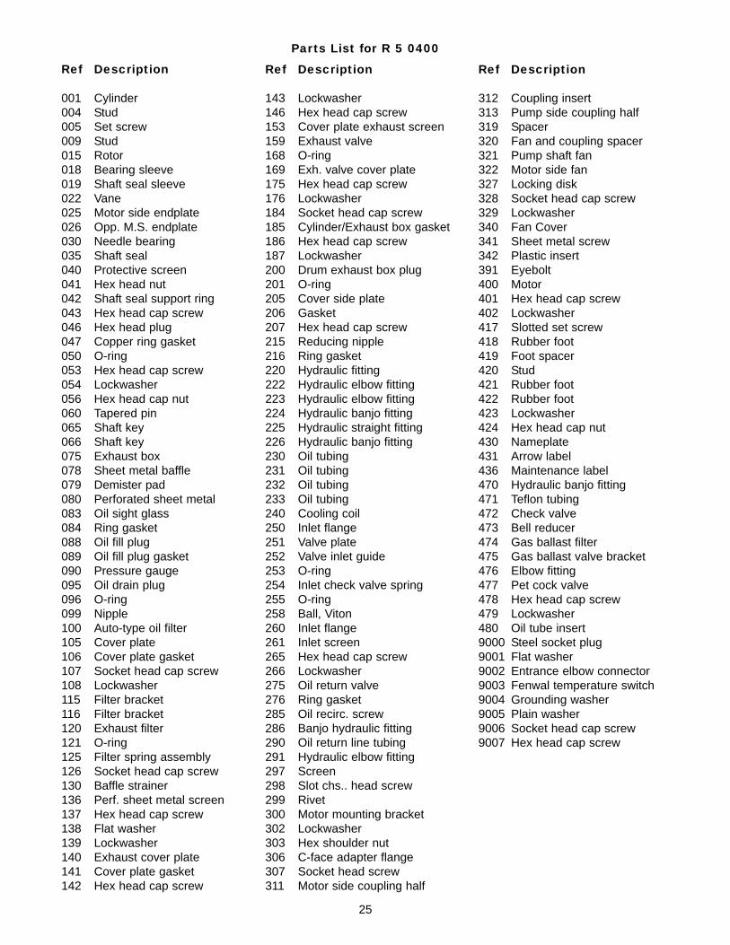
Parts List for R 5 0160
Ref Description
001 Cylinder004 Stud009 Stud015 Rotor018 Bearing sleeve022 Vane025 Motor side endplate026 Opp. M.S. endplate030 Needle bearing031 Endplate spacer032 Pump spacer034 Slotted chs. hd. cap screw035 Shaft seal040 Protective screen042 Shaft seal retaining plate043 Hex head cap screw046 Hex head plug047 Copper ring gasket050 O-ring053 Hex head cap screw054 Lockwasher056 Hex head cap nut060 Tapered pin065 Shaft key066 Shaft key075 Exhaust box078 Sheet metal baffle079 Demister pad083 Oil sight glass084 Ring gasket088 Oil fill plug089 Oil fill plug gasket090 Pressure gauge095 Oil drain plug096 O-ring099 Nipple100 Auto-type oil filter115 Filter bracket120 Exhaust filter121 O-ring125 Filter spring assembly126 Socket head cap screw130 Baffle strainer136 Baffle strainer frame140 Exhaust cover plate141 Cover plate gasket142 Hex head cap screw143 Lockwasher146 Hex head cap screw152 Lockwasher153 Exhaust silencer154 Gasket159 Exhaust valve168 O-ring169 Exh. valve cover plate175 Stud
Ref Description
322 Motor side fan340 Fan Cover341 Sheet metal screw342 Plastic insert390 Eyebolt adapter391 Eyebolt392 Lockwasher393 Hex head cap screw400 Motor401 Hex head cap screw402 Lockwasher416 Stud417 Slotted set screw419 Foot spacer420 Flat washer421 Rubber foot423 Washer424 Hex head cap nut430 Nameplate431 Arrow label436 Maintenance label470 Hydraulic fitting471 Teflon tubing472 Check valve473 Bell reducer474 Gas ballast filter475 Gas ballast valve bracket476 Elbow fitting477 Pet cock valve 478 Hex head cap screw479 Lockwasher480 Oil tube insert9000 Steel socket plug9001 Hydraulic adapter
Ref Description
176 Lockwasher177 Hex head nut180 Plug185 Gasket186 Hex head cap screw187 Lockwasher189 Stud190 Lockwasher191 Hex head nut200 Drum exhaust box plug201 O-ring205 Cover side plate206 Gasket207 Hex head cap screw208 Lockwasher220 Hydraulic fitting222 Hydraulic fitting223 Hydraulic fitting224 Hydraulic fitting230 Oil tubing231 Oil tubing232 Oil tubing240 Cooling coil250 Inlet flange251 Valve guide252 Valve plate253 O-ring254 Inlet check valve spring255 O-ring260 Inlet flange261 Inlet screen265 Hex head cap screw266 Lockwasher270 Plug271 Ring gasket275 Oil return valve276 Ring gasket285 Oil recirc. screw286 Banjo hydraulic fitting290 Oil return line tubing291 Hydraulic fitting292 Carburetor jet300 Motor mounting bracket302 Lockwasher303 Hex shoulder nut304 Socket hd. machine screw305 Flat washer306 C-face adapter flange307 Socket head screw311 Motor side coupling half312 Coupling insert313 Pump side coupling half315 Protective screen318 Protective screen319 Spacer321 Pump shaft fan
23
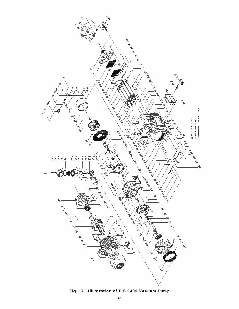
Fig. 17 - Illustration of R 5 0400 Vacuum Pump24
Parts List for R 5 0400
Ref Description
001 Cylinder004 Stud005 Set screw009 Stud015 Rotor018 Bearing sleeve019 Shaft seal sleeve022 Vane025 Motor side endplate026 Opp. M.S. endplate030 Needle bearing035 Shaft seal040 Protective screen041 Hex head nut042 Shaft seal support ring043 Hex head cap screw046 Hex head plug047 Copper ring gasket050 O-ring053 Hex head cap screw054 Lockwasher056 Hex head cap nut060 Tapered pin065 Shaft key066 Shaft key075 Exhaust box078 Sheet metal baffle079 Demister pad080 Perforated sheet metal083 Oil sight glass084 Ring gasket088 Oil fill plug089 Oil fill plug gasket090 Pressure gauge095 Oil drain plug096 O-ring099 Nipple100 Auto-type oil filter105 Cover plate106 Cover plate gasket107 Socket head cap screw108 Lockwasher115 Filter bracket116 Filter bracket120 Exhaust filter121 O-ring125 Filter spring assembly126 Socket head cap screw130 Baffle strainer136 Perf. sheet metal screen137 Hex head cap screw138 Flat washer139 Lockwasher140 Exhaust cover plate141 Cover plate gasket142 Hex head cap screw
Ref Description
312 Coupling insert313 Pump side coupling half319 Spacer320 Fan and coupling spacer321 Pump shaft fan322 Motor side fan327 Locking disk328 Socket head cap screw329 Lockwasher340 Fan Cover341 Sheet metal screw342 Plastic insert391 Eyebolt400 Motor401 Hex head cap screw402 Lockwasher417 Slotted set screw418 Rubber foot419 Foot spacer420 Stud421 Rubber foot422 Rubber foot423 Lockwasher424 Hex head cap nut430 Nameplate431 Arrow label436 Maintenance label470 Hydraulic banjo fitting471 Teflon tubing472 Check valve473 Bell reducer474 Gas ballast filter475 Gas ballast valve bracket476 Elbow fitting477 Pet cock valve 478 Hex head cap screw479 Lockwasher480 Oil tube insert9000 Steel socket plug9001 Flat washer9002 Entrance elbow connector9003 Fenwal temperature switch9004 Grounding washer9005 Plain washer9006 Socket head cap screw9007 Hex head cap screw
Ref Description
143 Lockwasher146 Hex head cap screw153 Cover plate exhaust screen159 Exhaust valve168 O-ring169 Exh. valve cover plate175 Hex head cap screw176 Lockwasher184 Socket head cap screw185 Cylinder/Exhaust box gasket186 Hex head cap screw187 Lockwasher200 Drum exhaust box plug201 O-ring205 Cover side plate206 Gasket207 Hex head cap screw215 Reducing nipple216 Ring gasket220 Hydraulic fitting222 Hydraulic elbow fitting223 Hydraulic elbow fitting224 Hydraulic banjo fitting225 Hydraulic straight fitting226 Hydraulic banjo fitting230 Oil tubing231 Oil tubing232 Oil tubing233 Oil tubing240 Cooling coil250 Inlet flange251 Valve plate252 Valve inlet guide253 O-ring254 Inlet check valve spring255 O-ring258 Ball, Viton260 Inlet flange261 Inlet screen265 Hex head cap screw266 Lockwasher275 Oil return valve276 Ring gasket285 Oil recirc. screw286 Banjo hydraulic fitting290 Oil return line tubing291 Hydraulic elbow fitting297 Screen298 Slot chs.. head screw299 Rivet300 Motor mounting bracket302 Lockwasher303 Hex shoulder nut306 C-face adapter flange307 Socket head screw311 Motor side coupling half
25
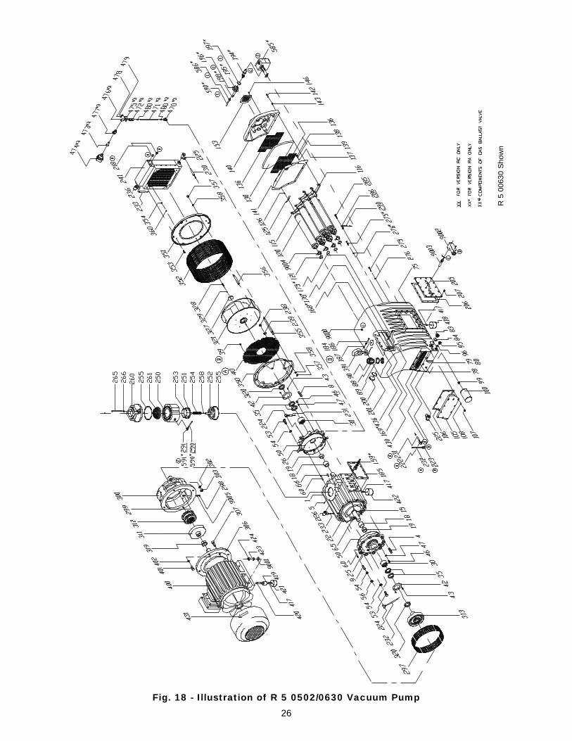
Fig. 18 - Illustration of R 5 0502/0630 Vacuum Pump26
R 5
006
30 S
how
n
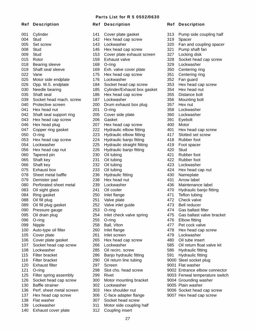
Parts List for R 5 0502/0630
Ref Description
001 Cylinder004 Stud005 Set screw008 Stud009 Stud015 Rotor018 Bearing sleeve019 Shaft seal sleeve022 Vane025 Motor side endplate026 Opp. M.S. endplate030 Needle bearing035 Shaft seal039 Socket head mach. screw040 Protective screen041 Hex head nut042 Shaft seal support ring043 Hex head cap screw046 Hex head plug047 Copper ring gasket050 O-ring053 Hex head cap screw054 Lockwasher056 Hex head cap nut060 Tapered pin065 Shaft key066 Shaft key075 Exhaust box078 Sheet metal baffle079 Demister pad080 Perforated sheet metal083 Oil sight glass084 Ring gasket088 Oil fill plug089 Oil fill plug gasket090 Pressure gauge095 Oil drain plug096 O-ring099 Nipple100 Auto-type oil filter105 Cover plate106 Cover plate gasket107 Socket head cap screw108 Lockwasher115 Filter bracket116 Filter bracket120 Exhaust filter121 O-ring125 Filter spring assembly126 Socket head cap screw130 Baffle strainer136 Perf. sheet metal screen137 Hex head cap screw138 Flat washer139 Lockwasher140 Exhaust cover plate
Ref Description
313 Pump side coupling half319 Spacer320 Fan and coupling spacer321 Pump shaft fan327 Locking disk328 Socket head cap screw329 Lockwasher350 Centering ring351 Centering ring352 Fan guard353 Hex head cap screw354 Hex head nut355 Distance bolt356 Mounting bolt357 Hex nut358 Lockwasher360 Lockwasher391 Eyebolt400 Motor401 Hex head cap screw417 Slotted set screw418 Rubber foot419 Foot spacer420 Stud421 Rubber foot422 Rubber foot423 Lockwasher424 Hex head cap nut430 Nameplate431 Arrow label436 Maintenance label470 Hydraulic banjo fitting471 Teflon tubing472 Check valve473 Bell reducer474 Gas ballast filter475 Gas ballast valve bracket476 Elbow fitting477 Pet cock valve 478 Hex head cap screw479 Lockwasher480 Oil tube insert585 Oil return float valve kit586 Hydraulic fitting591 Hydraulic fitting9000 Steel socket plug9001 Flat washer9002 Entrance elbow connector9003 Fenwal temperature switch9004 Grounding washer9005 Plain washer9006 Socket head cap screw9007 Hex head cap screw
Ref Description
141 Cover plate gasket142 Hex head cap screw143 Lockwasher146 Hex head cap screw153 Cover plate exhaust screen159 Exhaust valve168 O-ring169 Exh. valve cover plate175 Hex head cap screw176 Lockwasher184 Socket head cap screw185 Cylinder/Exhaust box gasket186 Hex head cap screw187 Lockwasher200 Drum exhaust box plug201 O-ring205 Cover side plate206 Gasket207 Hex head cap screw222 Hydraulic elbow fitting223 Hydraulic elbow fitting224 Hydraulic banjo fitting225 Hydraulic straight fitting226 Hydraulic banjo fitting230 Oil tubing231 Oil tubing232 Oil tubing233 Oil tubing236 Hydraulic fitting238 Hex head nut239 Lockwasher241 Oil cooler250 Inlet flange251 Valve plate252 Valve inlet guide253 O-ring254 Inlet check valve spring255 O-ring258 Ball, Viton260 Inlet flange261 Inlet screen265 Hex head cap screw266 Lockwasher285 Oil recirc. screw286 Banjo hydraulic fitting290 Oil return line tubing297 Screen298 Slot chs. head screw299 Rivet300 Motor mounting bracket302 Lockwasher303 Hex shoulder nut306 C-face adapter flange307 Socket head screw311 Motor side coupling half312 Coupling insert
27

28
Busch Inc. Factory Service Centers
California Illinois
13826 Struikman Road 430 Windy Point DriveCerritos, CA 90703 Glendale Heights, IL 60139Phone (562) 926-8422 Phone (630) 545-1310Fax (562) 926-7262 Fax (630) [email protected] [email protected]
New Jersey Puerto Rico
39 Davis Street 420 E Street, Suite 4South Plainfield, NJ 07080 Minillas Industrial ParkPhone (908) 561-3233 Bayamon, PR 00959-1901Fax (908) 561-3909 Phone (787) [email protected] Fax (787) 798-5033
Texas Virginia
15411 Vantage Pkwy W., Suite 216 516 Viking DriveHouston, TX 77032 Virginia Beach, VA 23452Phone (281) 449-2381 Phone (757) 463-7800Fax (281) 449-2383 Fax (757) [email protected] [email protected]
29

P/N 872.004.01Revision 12/04
Busch, Inc.516 Viking DriveVirginia Beach, Virginia 23452Phone: (757) 463-7800FAX: (757) 463-7407


