26
Maintenance Manual MM-1736 System Saver HP Air Dryer Revised 12-17
Maintenance Manual MM-1736
System Saver HP Air DryerRevised 12-17
Service Notes
Information contained in this publication was in effect at the time the publication was approved for printing and is subject to change without notice or liability. WABCO reserves the right to revise the information presented or to discontinue the production of parts described at any time.
WABCO Maintenance Manual MM-1736 (Revised 12-17)
About This ManualThis manual provides service and repair procedures for Meritor WABCO’s System Saver HP air dryer.
Before You Begin1. Read and understand all instructions and procedures before
you begin to service components.
2. Read and observe all Warning and Caution hazard alert messages in this publication. They provide information that can help prevent serious personal injury, damage to components, or both.
3. Follow your company’s maintenance and service, installation, and diagnostics guidelines.
4. Use special tools when required to help avoid serious personal injury and damage to components.
Hazard Alert Messages and Torque Symbols
WARNINGA Warning alerts you to an instruction or procedure that you must follow exactly to avoid serious personal injury and damage to components.
CAUTIONA Caution alerts you to an instruction or procedure that you must follow exactly to avoid damage to components.
@ This symbol alerts you to tighten fasteners to a specified torque value.
How to Obtain Additional Maintenance, Service and Product InformationVisit meritorwabco.com to access additional information.
Contact the Meritor OnTrac™ Customer Call Center at 866-668-7221 (United States and Canada); 001-800-889-1834 (Mexico); or email [email protected].
If Tools and Supplies are Specified in This ManualContact Meritor’s Commercial Vehicle Aftermarket at 888-725-9355.
Contents
pg. 1 Section 1: IntroductionOverviewAir Dryer IdentificationHow the Air Dryer Works
2 Air Dryer Cycle4 Air Dryer Components6 Dryer Identification
Description of Components
8 Section 2: Component Removal and InstallationComponent ReplacementRequirements
9 Component Removal and InstallationDesiccant Cartridge
10 Outlet Check Valve AssemblyHeater Assembly
11 Turbo Cut-Off Valve AssemblyGovernorPurge Valve Assembly
12 Air Dryer Assembly
13 Section 3: Troubleshooting and TestingMaintenanceMaintenance Tips
14 Troubleshooting18 Tests
Heater ResistanceElectric Power to Dryer
19 Leak TestAir Pressure ChecksOperational Test for System Saver Series Air Dryers
20 Section 4: Appendix I — GlossaryDefinitionsBasic Air System/Air Dryer Terms
21 Section 5: Appendix II — Application InformationRecommendationsOperating Environment
22 System Saver IP Installation Criteria

1 Introduction
1WABCO Maintenance Manual MM-1736 (Revised 12-17)
1 IntroductionOverviewMaintenance Manual 1736 contains troubleshooting steps and service information for the Meritor WABCO System Saver HP single cartridge air dryers.
NOTE: If you have a Meritor WABCO System Saver (1200 or 1800) single cartridge air dryer, use Maintenance Manual 34, Meritor WABCO System Saver Series (1200 and 1800) Single Cartridge Air Dryers. If you have a Meritor WABCO System Saver Twin air dryer, use Maintenance Manual 35, Meritor WABCO System Saver Twin Air Dryer. To obtain these publications, refer to the Service Notes page on the front inside cover of this manual.
Air Dryer IdentificationSystem Saver HP: Has the governor integrated into the body of the air dryer and also has an integrated purge tank. Figure 1.1.
Figure 1.1
How the Air Dryer WorksDuring system pressure build-up, compressed air passes into the air dryer where the filter system removes contaminants and passes the air into the drying stage.
Moisture-laden air passes through the desiccant bed in the air dryer cartridge and moisture is retained by the desiccant. Moisture that condenses out also collects in the base of the dryer. When the compressor unloads, the water is expelled and dried air flows back through the dryer, drying the desiccant for the next cycle.
Figure 1.1
4013285a
PURGETANK
GOVERNOR

1 Introduction
2 WABCO Maintenance Manual MM-1736 (Revised 12-17)
Air Dryer CycleA single cartridge air dryer cycle is illustrated in Table A.
Table A:
The governor turns the compressor loading on when supply tank pressure drops below cut-in pressure, between 105 psi and 115 psi (724-792 kPa) depending on governor settings.
Compressed air passes into the air dryer at the inlet port:
� Moisture-laden air and contaminants enter the desiccant.
� Moisture is retained by desiccant; moisture also collects in the base of the dryer.
� Contaminants are removed as air passes through the desiccant bed.
4013565a
CONTROL“WET” AIR“DRY” AIRCONTROL/DRYLINESCOMPRESSORINTAKE LINE
4013286a
INLETPORT 1
CARTRIDGE
OUTLETPORT 2.1/2.2
1 Introduction
3WABCO Maintenance Manual MM-1736 (Revised 12-17)
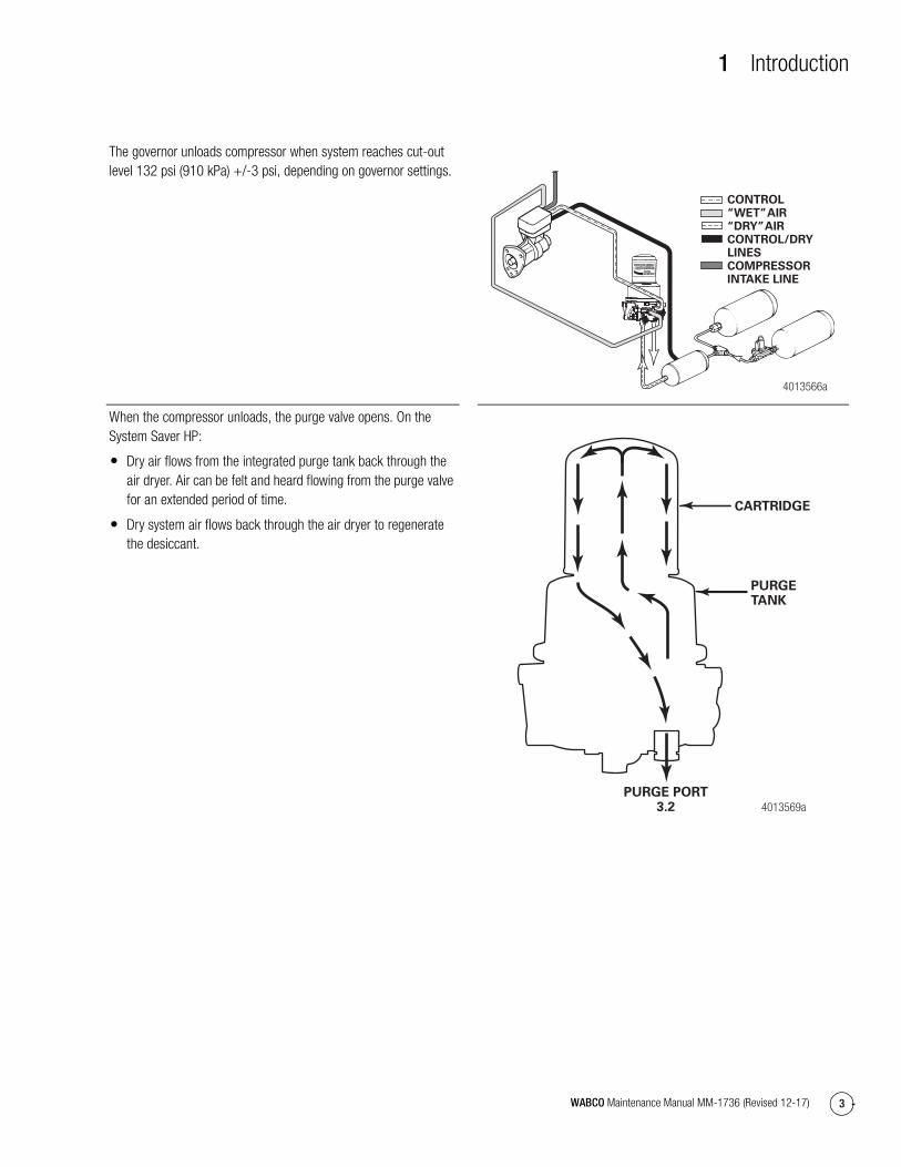
The governor unloads compressor when system reaches cut-out level 132 psi (910 kPa) +/-3 psi, depending on governor settings.
When the compressor unloads, the purge valve opens. On the System Saver HP:
� Dry air flows from the integrated purge tank back through the air dryer. Air can be felt and heard flowing from the purge valve for an extended period of time.
� Dry system air flows back through the air dryer to regenerate the desiccant.
4013566a
CONTROL“WET” AIR“DRY” AIRCONTROL/DRYLINESCOMPRESSORINTAKE LINE
4013569aPURGE PORT
3.2
CARTRIDGE
PURGETANK
1 Introduction
4 WABCO Maintenance Manual MM-1736 (Revised 12-17)
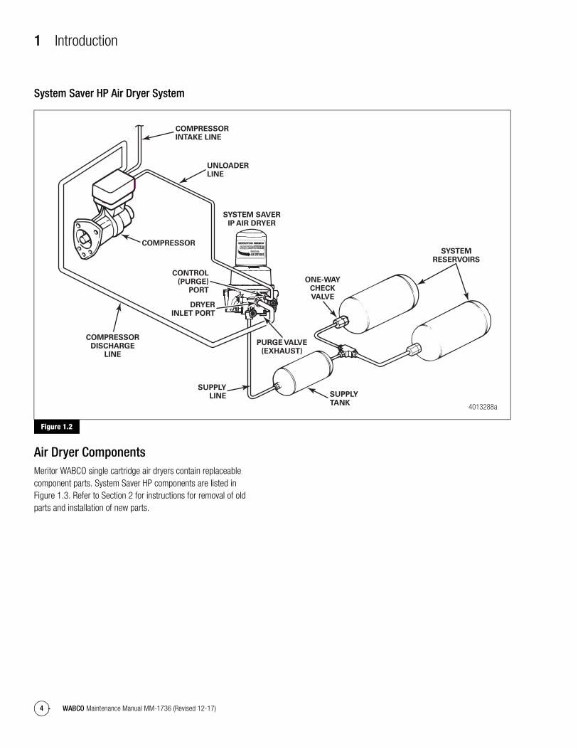
System Saver HP Air Dryer System
Figure 1.2
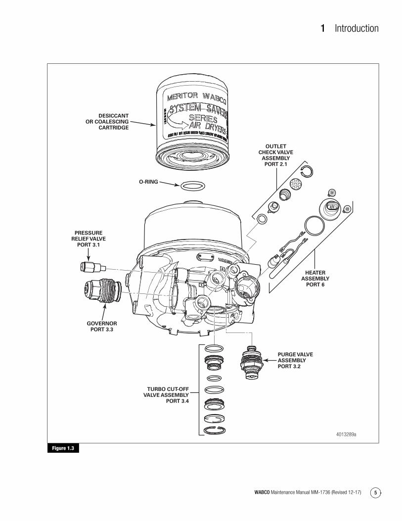
Air Dryer ComponentsMeritor WABCO single cartridge air dryers contain replaceable component parts. System Saver HP components are listed in Figure 1.3. Refer to Section 2 for instructions for removal of old parts and installation of new parts.
Figure 1.2
4013288a
COMPRESSORDISCHARGE
LINE
COMPRESSOR
CONTROL(PURGE)
PORT
DRYERINLET PORT
COMPRESSORINTAKE LINE
SUPPLYTANK
SYSTEMRESERVOIRS
ONE-WAYCHECKVALVE
SYSTEM SAVER IP AIR DRYER
UNLOADERLINE
SUPPLYLINE
PURGE VALVE(EXHAUST)
1 Introduction
5WABCO Maintenance Manual MM-1736 (Revised 12-17)
Figure 1.3
Figure 1.3
4013289a
GOVERNORPORT 3.3
PRESSURERELIEF VALVE
PORT 3.1
DESICCANTOR COALESCING
CARTRIDGE
O-RING
HEATERASSEMBLY
PORT 6
PURGE VALVEASSEMBLYPORT 3.2
TURBO CUT-OFFVALVE ASSEMBLY
PORT 3.4
OUTLETCHECK VALVE
ASSEMBLYPORT 2.1
1 Introduction
6 WABCO Maintenance Manual MM-1736 (Revised 12-17)
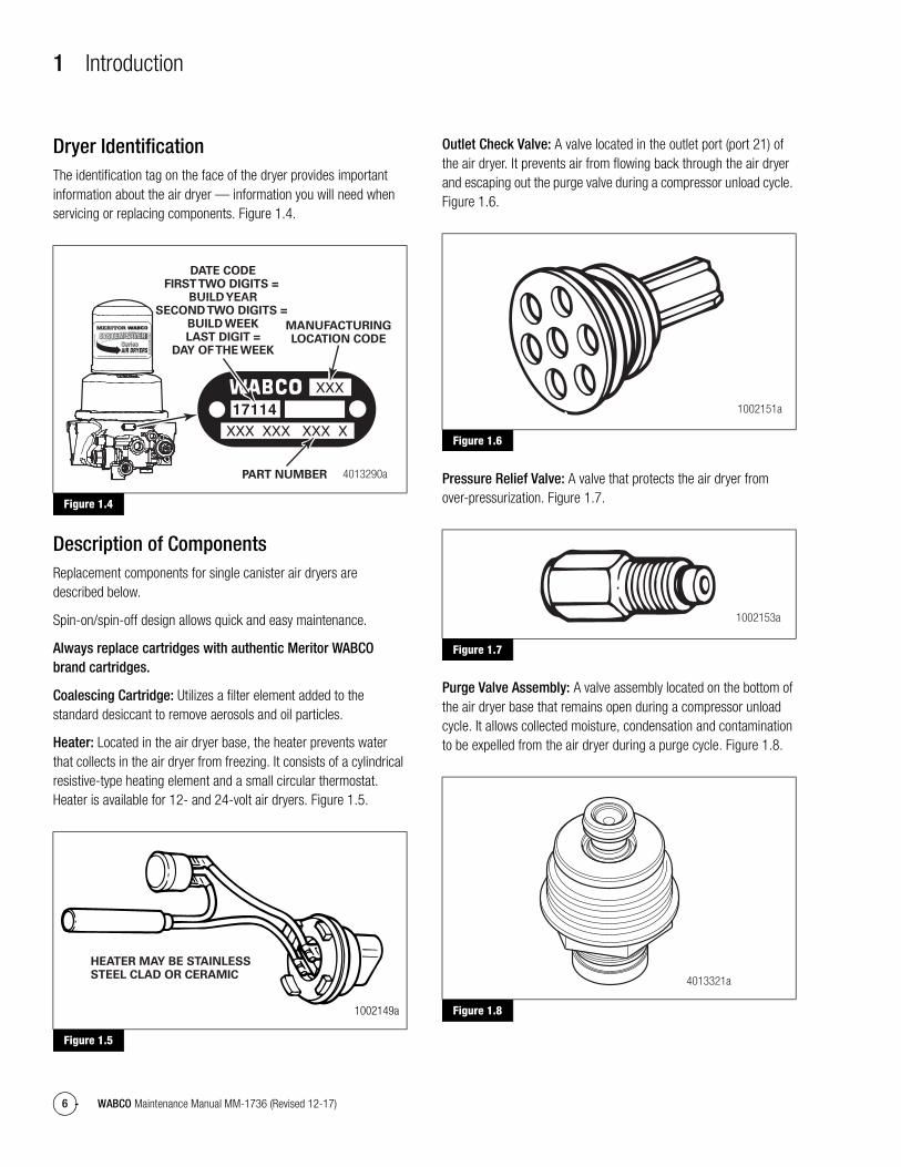
Dryer IdentificationThe identification tag on the face of the dryer provides important information about the air dryer — information you will need when servicing or replacing components. Figure 1.4.
Figure 1.4
Description of ComponentsReplacement components for single canister air dryers are described below.
Spin-on/spin-off design allows quick and easy maintenance.
Always replace cartridges with authentic Meritor WABCO brand cartridges.
Coalescing Cartridge: Utilizes a filter element added to the standard desiccant to remove aerosols and oil particles.
Heater: Located in the air dryer base, the heater prevents water that collects in the air dryer from freezing. It consists of a cylindrical resistive-type heating element and a small circular thermostat. Heater is available for 12- and 24-volt air dryers. Figure 1.5.
Figure 1.5
Outlet Check Valve: A valve located in the outlet port (port 21) of the air dryer. It prevents air from flowing back through the air dryer and escaping out the purge valve during a compressor unload cycle. Figure 1.6.
Figure 1.6
Pressure Relief Valve: A valve that protects the air dryer from over-pressurization. Figure 1.7.
Figure 1.7
Purge Valve Assembly: A valve assembly located on the bottom of the air dryer base that remains open during a compressor unload cycle. It allows collected moisture, condensation and contamination to be expelled from the air dryer during a purge cycle. Figure 1.8.
Figure 1.8
Figure 1.4
Figure 1.5
4013290a
17114
DATE CODEFIRST TWO DIGITS =
BUILD YEARSECOND TWO DIGITS =
BUILD WEEKLAST DIGIT =
DAY OF THE WEEK
MANUFACTURINGLOCATION CODE
PART NUMBER
1002149a
HEATER MAY BE STAINLESSSTEEL CLAD OR CERAMIC
Figure 1.6
Figure 1.7
Figure 1.8
1002151a
1002153a
4013321a
1 Introduction
7WABCO Maintenance Manual MM-1736 (Revised 12-17)
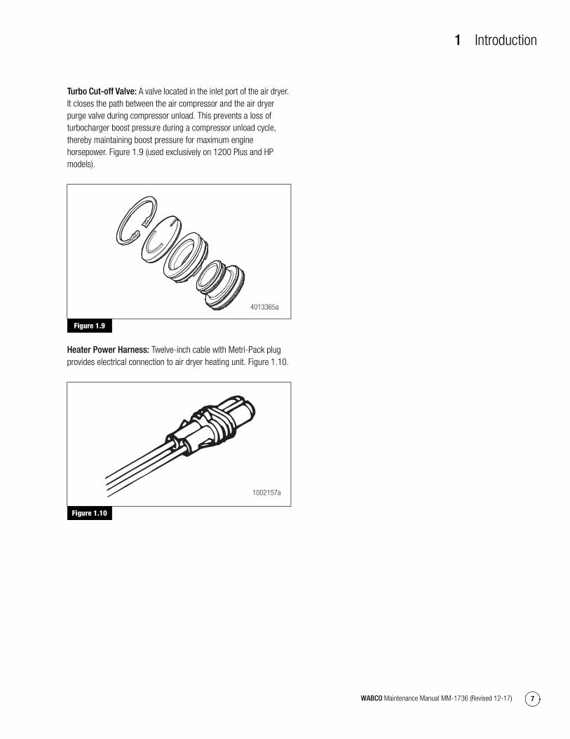
Turbo Cut-off Valve: A valve located in the inlet port of the air dryer. It closes the path between the air compressor and the air dryer purge valve during compressor unload. This prevents a loss of turbocharger boost pressure during a compressor unload cycle, thereby maintaining boost pressure for maximum engine horsepower. Figure 1.9 (used exclusively on 1200 Plus and HP models).
Figure 1.9
Heater Power Harness: Twelve-inch cable with Metri-Pack plug provides electrical connection to air dryer heating unit. Figure 1.10.
Figure 1.10
Figure 1.9
Figure 1.10
4013365a
1002157a

2 Component Removal and Installation
8 WABCO Maintenance Manual MM-1736 (Revised 12-17)
2 Component Removal and InstallationHazard Alert MessagesRead and observe all Warning and Caution hazard alert messages in this publication. They provide information that can help prevent serious personal injury, damage to components, or both.
WARNINGTo prevent serious eye injury, always wear safe eye protection when you perform vehicle maintenance or service.
Park the vehicle on a level surface. Block the wheels to prevent the vehicle from moving. Support the vehicle with safety stands. Do not work under a vehicle supported only by jacks. Jacks can slip and fall over. Serious personal injury and damage to components can result.
Remove all pressure from the air system before you disconnect any component, including the desiccant cartridge. Pressurized air can cause serious personal injury.
NOTE: The pressure protection elements are not serviceable on the System Saver HP. The entire air dryer needs to be replaced if these parts are not operating effectively.
Component Replacement
RequirementsRefer to Table B for component replacement requirements. If necessary, you may also refer to Table D for System Saver Series air dryer troubleshooting. Before replacing any air dryer component, verify that the air compressor and air governor are working correctly, then drain the air tanks. Repair or replace these parts, if necessary. Check the entire air system for leaks, and repair as necessary. When draining air tanks before servicing the air dryer, check for water and/or oil that may have accumulated in the tanks. Water and/or oil in the air tanks could indicate a problem with the dryer or compressor.
Table B:
Replacement Requirements
Component When to Replace Why
Cartridge Every two to three years for standard dessicant.
Every one to two years for coalescing.
Preventative maintenance.
When compressor is replaced. Contaminated cartridge.
Water in supply tank. Saturated or contaminated cartridge, high duty cycle (wrong application of air dryer).
Heater Assembly Water collecting in air dryer is freezing — electrical power to dryer is OK.
Heater assembly not working (internal short or open circuit).
Outlet Check Valve Air continues to flow from purge valve after purge cycle, but stops flowing when the compressor load cycle begins.
Valve is stuck in the open position, or not functioning correctly.
No pressure build-up in system, everything else is OK.
Valve is stuck in closed position.
Purge Valve No purge cycle when compressor unloads — normal pressure at dryer control port 4 (governor port).
Valve is stuck in the closed position, or not functioning correctly.
Air flows from purge valve during compressor’s load cycle — no pressure at dryer control port.
Valve is stuck in the open position, or not functioning correctly.

2 Component Removal and Installation
9WABCO Maintenance Manual MM-1736 (Revised 12-17)
NOTE: When replacing air dryer components, use only Meritor WABCO replacement parts.
The exploded view of the air dryer in Section 1 shows the location of the various air dryer components.
Component Removal and Installation
Desiccant CartridgeIMPORTANT NOTE: For air dryer part numbers 432 480 001 0, 432 480 101 0 and 432 480 141 0 (see dryer tag), you must use air cartridges S432 901 248 2, S432 901 250 2 and S432 480 004 2.
1. Replacement kit contains one cartridge and one O-ring. Figure 2.1.
Figure 2.1
2. Loosen and remove the old cartridge. Use strap wrench if necessary.
3. Remove and discard O-ring from dryer base.
NOTE: If the seal seats are damaged so badly that a tight seal cannot be maintained, replace the air dryer. Refer to Figure 2.2.
4. Inspect and clean seal seat. Repair any minor damage.
5. Lubricate and install the new O-ring on the stem.
6. Lubricate cartridge seal.
7. Thread replacement cartridge onto the base until the seal touches the base. Then, tighten the cartridge ONE additional turn. DO NOT OVERTIGHTEN. Figure 2.2. If the cartridge will not fully spin on the dryer, the wrong cartridge is being used (see IMPORTANT NOTE).
Figure 2.2
Turbo Cut-Off Valve Air compressor stuck pumping, TCU remains open. System will build pressure until safety valve opens in system.
Signal line loss.
Air flows from purge valve during compressor unload cycle after purge cycle, and flow is noticeably stronger at high engine RPM, especially under load.
Turbo cut-off valve leaking.
No pressure build-up in system — high compressor discharge line pressure.
Valve stuck in closed position.
Replacement Requirements
Component When to Replace Why
Figure 2.1
1002234a
Figure 2.2
1002164a
SEAL
SEAL SEAT
O-RING
2 Component Removal and Installation
10 WABCO Maintenance Manual MM-1736 (Revised 12-17)
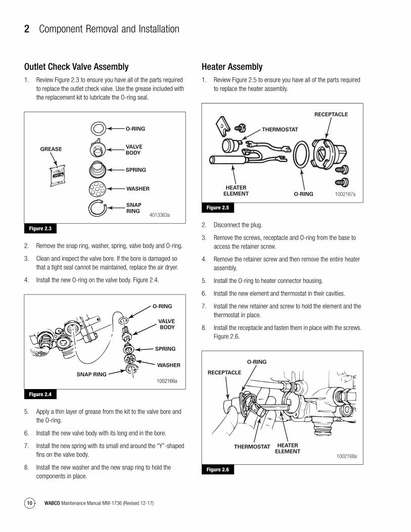
Outlet Check Valve Assembly1. Review Figure 2.3 to ensure you have all of the parts required
to replace the outlet check valve. Use the grease included with the replacement kit to lubricate the O-ring seal.
Figure 2.3
2. Remove the snap ring, washer, spring, valve body and O-ring.
3. Clean and inspect the valve bore. If the bore is damaged so that a tight seal cannot be maintained, replace the air dryer.
4. Install the new O-ring on the valve body. Figure 2.4.
Figure 2.4
5. Apply a thin layer of grease from the kit to the valve bore and the O-ring.
6. Install the new valve body with its long end in the bore.
7. Install the new spring with its small end around the “Y”-shaped fins on the valve body.
8. Install the new washer and the new snap ring to hold the components in place.
Heater Assembly1. Review Figure 2.5 to ensure you have all of the parts required
to replace the heater assembly.
Figure 2.5
2. Disconnect the plug.
3. Remove the screws, receptacle and O-ring from the base to access the retainer screw.
4. Remove the retainer screw and then remove the entire heater assembly.
5. Install the O-ring to heater connector housing.
6. Install the new element and thermostat in their cavities.
7. Install the new retainer and screw to hold the element and the thermostat in place.
8. Install the receptacle and fasten them in place with the screws. Figure 2.6.
Figure 2.6
Figure 2.3
Figure 2.4
4013363a
O-RING
VALVEBODY
SNAPRING
SPRING
WASHER
GREASE
1002166aSNAP RING
WASHER
SPRING
O-RING
VALVEBODY
Figure 2.5
Figure 2.6
1002167a
THERMOSTAT
RECEPTACLE
O-RING
HEATERELEMENT
1002168a
O-RING
HEATERELEMENT
THERMOSTAT
RECEPTACLE
2 Component Removal and Installation
11WABCO Maintenance Manual MM-1736 (Revised 12-17)
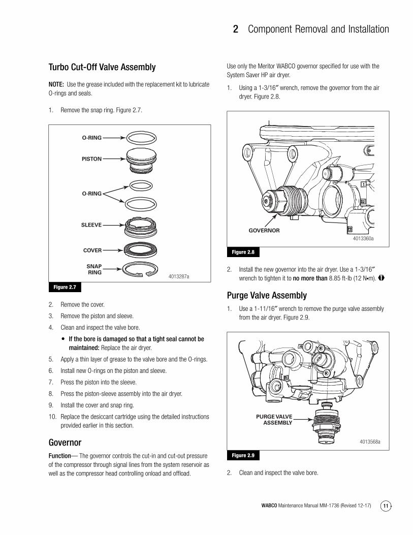
Turbo Cut-Off Valve Assembly
NOTE: Use the grease included with the replacement kit to lubricate O-rings and seals.
1. Remove the snap ring. Figure 2.7.
Figure 2.7
2. Remove the cover.
3. Remove the piston and sleeve.
4. Clean and inspect the valve bore.
� If the bore is damaged so that a tight seal cannot be maintained: Replace the air dryer.
5. Apply a thin layer of grease to the valve bore and the O-rings.
6. Install new O-rings on the piston and sleeve.
7. Press the piston into the sleeve.
8. Press the piston-sleeve assembly into the air dryer.
9. Install the cover and snap ring.
10. Replace the desiccant cartridge using the detailed instructions provided earlier in this section.
GovernorFunction— The governor controls the cut-in and cut-out pressure of the compressor through signal lines from the system reservoir as well as the compressor head controlling onload and offload.
Use only the Meritor WABCO governor specified for use with the System Saver HP air dryer.
1. Using a 1-3/16″ wrench, remove the governor from the air dryer. Figure 2.8.
Figure 2.8
2. Install the new governor into the air dryer. Use a 1-3/16″ wrench to tighten it to no more than 8.85 ft-lb (12 N�m). @
Purge Valve Assembly1. Use a 1-11/16″ wrench to remove the purge valve assembly
from the air dryer. Figure 2.9.
Figure 2.9
2. Clean and inspect the valve bore.
Figure 2.7
4013287a
O-RING
PISTON
O-RING
SLEEVE
COVER
SNAPRING
Figure 2.8
Figure 2.9
4013360a
GOVERNOR
4013568a
PURGE VALVEASSEMBLY

2 Component Removal and Installation
12 WABCO Maintenance Manual MM-1736 (Revised 12-17)
� If the bore is damaged so that a tight seal cannot be maintained: Replace the air dryer.
3. Install the purge valve assembly in the air dryer. Use a 1-11/16″ wrench to tighten it to no more than 11 ft-lb (15 N�m). @
Air Dryer Assembly
NOTE: This procedure is for removing and replacing a unit. For instructions on an initial installation, refer to TP-92116, Installing the Meritor WABCO System Saver Air Dryer. To obtain this publication, refer to the Service Notes page on the front inside cover of this manual.
1. Drain all pressure from the air system. Disconnect the air lines from port 1, port 2.2 and port 4.
Use markers to label the lines for correct reinstallation.
2. Disconnect the heater electrical plug from the heater receptacle.
3. Remove the three mounting bolts. Remove the air dryer from its mounting location. Figure 2.10.
Figure 2.10
4. Attach the new unit to the frame or mounting bracket with new mounting bolts and washers. Tighten the bolts to 22-30 ft-lb (30-40 N�m). Figure 2.11. @
Figure 2.11
5. Connect heater electrical plug to heater receptacle.
6. Reconnect all system air lines.
7. Test the installation for correct operation. Refer to the procedure in this section.
Figure 2.10
4013563a
Figure 2.11
4013564a
3 Troubleshooting and Testing
13WABCO Maintenance Manual MM-1736 (Revised 12-17)
3 Troubleshooting and TestingMaintenanceRead and observe all Warning and Caution hazard alert messages in this publication. They provide information that can help prevent serious personal injury, damage to components, or both.
WARNINGTo prevent serious eye injury, always wear safe eye protection when you perform vehicle maintenance or service.
Park the vehicle on a level surface. Block the wheels to prevent the vehicle from moving. Support the vehicle with safety stands. Do not work under a vehicle supported only by jacks. Jacks can slip and fall over. Serious personal injury and damage to components can result.
Remove all pressure from the air system before you disconnect any component, including the desiccant cartridge. Pressurized air can cause serious personal injury.
To keep your Meritor WABCO air dryer operating efficiently, the routine maintenance in Table C is recommended.
Table C:
Maintenance TipsWith correct maintenance, the Meritor WABCO air dryer will provide years of reliable service, even under adverse operating conditions. To provide additional protection against the harmful effects of extreme heat or cold, here are a few helpful tips.
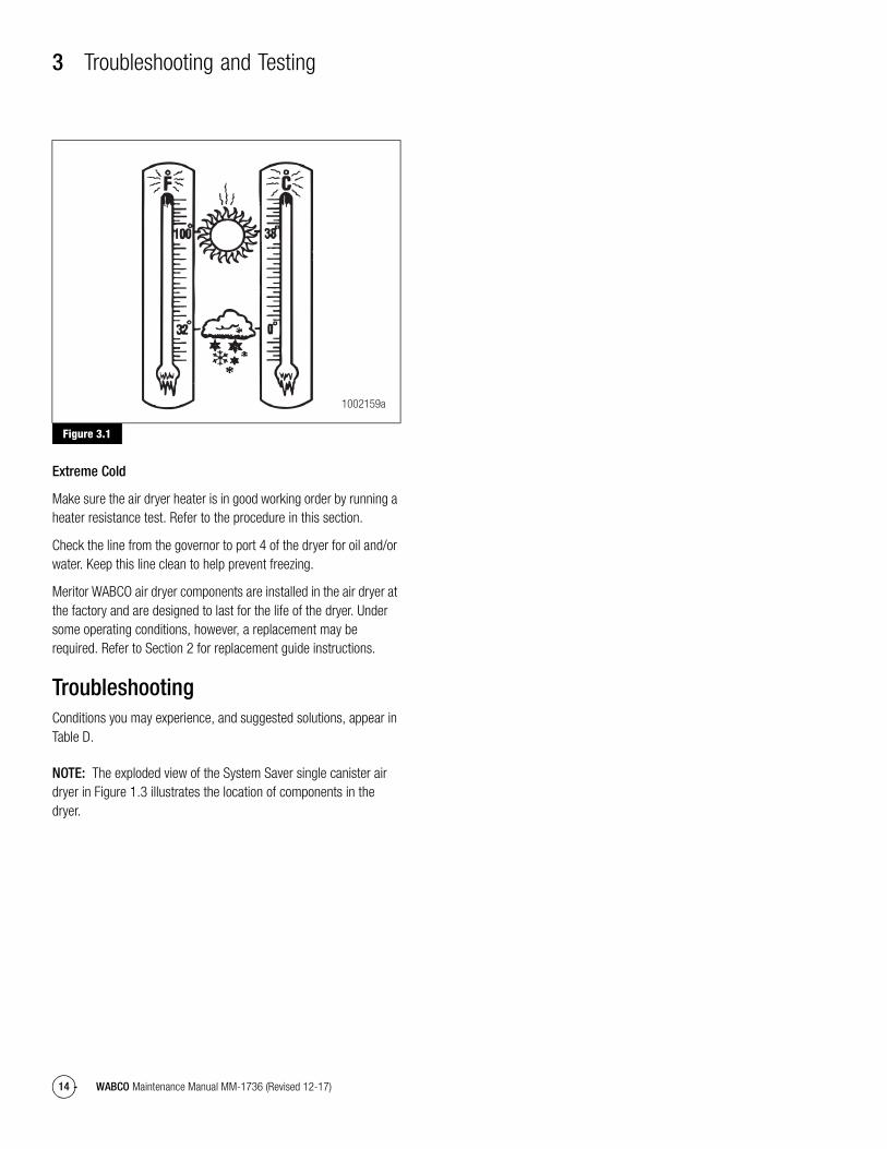
Extreme Heat
Make sure the compressor discharge line is long enough to keep air dryer inlet air below 175°F (80°C). Figure 3.1. (Refer to Section 5.)
Action Interval
Ensure the dryer purges when compressor unloads. Weekly.
Drain the purge tank (dedicated purge tank dryers). Weekly, or as recommended by the manufacturer.
Check for moisture in the system by opening the drain cock on vehicle system reservoirs slowly.
Weekly, or as recommended by the manufacturer, whichever is most frequent.
Replace the standard desiccant cartridge. Every two to three years, or more often depending on usage, vocation, and condition of compressor.
Whenever compressor is rebuilt.
Replace the coalescing cartridge. Every one to two years.
3 Troubleshooting and Testing
14 WABCO Maintenance Manual MM-1736 (Revised 12-17)
Figure 3.1
Extreme Cold
Make sure the air dryer heater is in good working order by running a heater resistance test. Refer to the procedure in this section.
Check the line from the governor to port 4 of the dryer for oil and/or water. Keep this line clean to help prevent freezing.
Meritor WABCO air dryer components are installed in the air dryer at the factory and are designed to last for the life of the dryer. Under some operating conditions, however, a replacement may be required. Refer to Section 2 for replacement guide instructions.
TroubleshootingConditions you may experience, and suggested solutions, appear in Table D.
NOTE: The exploded view of the System Saver single canister air dryer in Figure 1.3 illustrates the location of components in the dryer.
Figure 3.1
1002159a

3 Troubleshooting and Testing
15WABCO Maintenance Manual MM-1736 (Revised 12-17)
Table D: System Saver Series Air Dryer Troubleshooting
Condition Possible CausePurge Tank Air Dryers Solution
Dryer leaks from purge valve during compressor loaded cycle. The leak may cause excessive compressor cycling or prevent the system from building air pressure.
Purge valve frozen open (cold weather operation).
Yes Check heater. Repair/replace if necessary. Make sure governor to dryer port 4 line is free of water/oil.
Remove and inspect purge valve and clean water/oil from top of piston.
Debris under purge valve seat, such as particles from fittings or air inlet line.
Yes Remove and clean purge valve mating surfaces.
Remove cartridge and clean dryer sump area.
Purge valve washer installed upside-down.
Yes Ensure lip on aluminum washer faces DOWN, away from dryer.
Wrong air line connected to dryer port 4 (unloader port).
Yes Verify correct air line installation and correct as needed.
Purge valve snap ring not fully seated in groove.
Yes Seat snap ring fully into groove.
Regeneration cycle too long (more than 30 seconds), accompanied by loss of pressure in the supply tank.
Outlet check valve not seating. Yes Inspect and replace outlet check valve as needed.
Regeneration valve not shutting off regeneration airflow.
No Replace regeneration valve.
Regeneration cycle too short (less than 10 seconds).
High air system demands during compressor unloaded cycle.
Yes Increase air system capacity or reduce air demands.
Pressure-controlled check valve not installed in system or not working correctly.
Yes Check and replace pressure-controlled check valve as needed.
One-way check valve installed in system reservoir instead of, or with, pressure-controlled check valve.
No Remove one-way check valve. Make sure pressure-controlled check valve is installed correctly.
Regeneration valve not working. No Remove regeneration valve and clean oil from diaphragm. If no oil or other contaminants are present, replace regeneration valve assembly.
Air governor not working correctly.
Yes Inspect air governor. Repair/replace per manufacturer’s instructions.
Water in purge tank. Block in purge tank line. Yes Clear blockage. Replace desiccant cartridge.
3 Troubleshooting and Testing
16 WABCO Maintenance Manual MM-1736 (Revised 12-17)
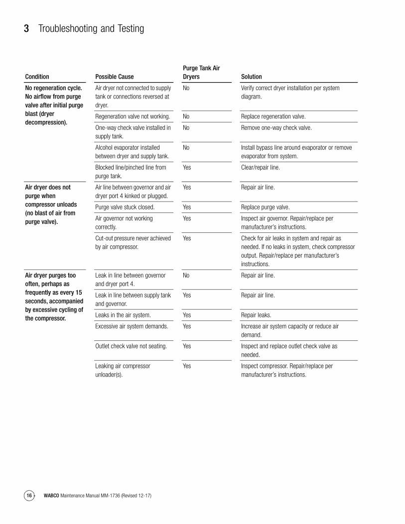
No regeneration cycle. No airflow from purge valve after initial purge blast (dryer decompression).
Air dryer not connected to supply tank or connections reversed at dryer.
No Verify correct dryer installation per system diagram.
Regeneration valve not working. No Replace regeneration valve.
One-way check valve installed in supply tank.
No Remove one-way check valve.
Alcohol evaporator installed between dryer and supply tank.
No Install bypass line around evaporator or remove evaporator from system.
Blocked line/pinched line from purge tank.
Yes Clear/repair line.
Air dryer does not purge when compressor unloads (no blast of air from purge valve).
Air line between governor and air dryer port 4 kinked or plugged.
Yes Repair air line.
Purge valve stuck closed. Yes Replace purge valve.
Air governor not working correctly.
Yes Inspect air governor. Repair/replace per manufacturer’s instructions.
Cut-out pressure never achieved by air compressor.
Yes Check for air leaks in system and repair as needed. If no leaks in system, check compressor output. Repair/replace per manufacturer’s instructions.
Air dryer purges too often, perhaps as frequently as every 15 seconds, accompanied by excessive cycling of the compressor.
Leak in line between governor and dryer port 4.
No Repair air line.
Leak in line between supply tank and governor.
Yes Repair air line.
Leaks in the air system. Yes Repair leaks.
Excessive air system demands. Yes Increase air system capacity or reduce air demand.
Outlet check valve not seating. Yes Inspect and replace outlet check valve as needed.
Leaking air compressor unloader(s).
Yes Inspect compressor. Repair/replace per manufacturer’s instructions.
Condition Possible CausePurge Tank Air Dryers Solution
3 Troubleshooting and Testing
17WABCO Maintenance Manual MM-1736 (Revised 12-17)
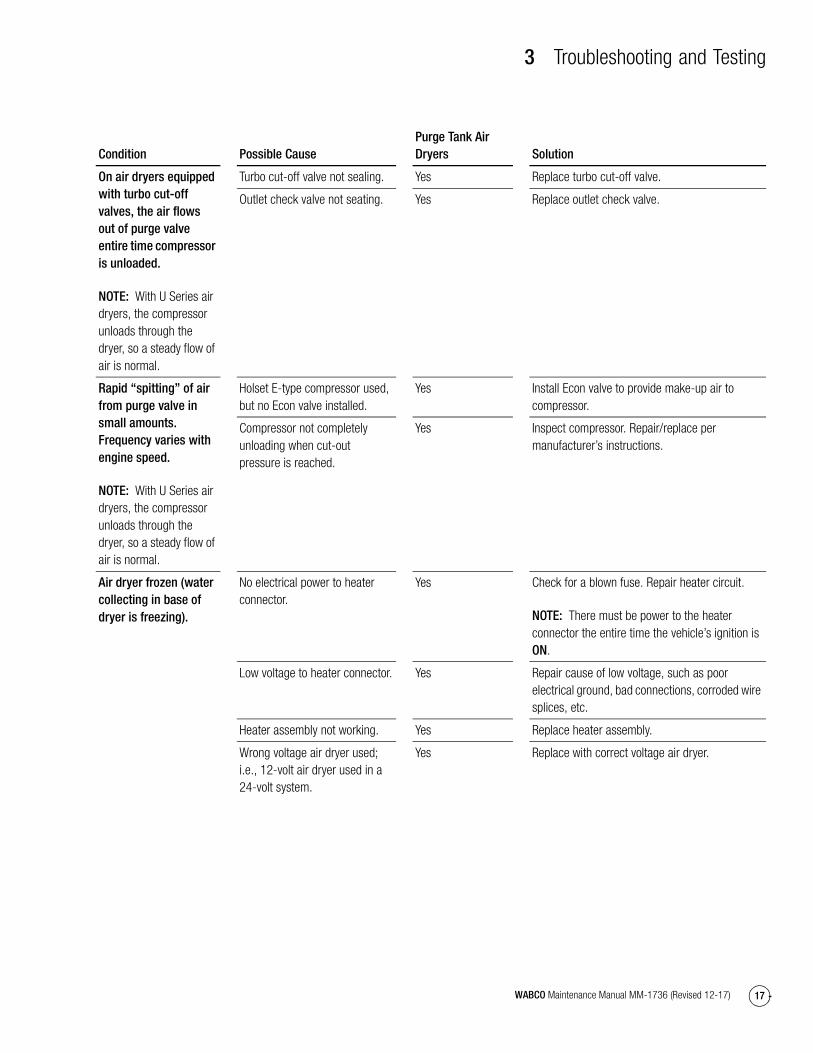
On air dryers equipped with turbo cut-off valves, the air flows out of purge valve entire time compressor is unloaded.
NOTE: With U Series air dryers, the compressor unloads through the dryer, so a steady flow of air is normal.
Turbo cut-off valve not sealing. Yes Replace turbo cut-off valve.
Outlet check valve not seating. Yes Replace outlet check valve.
Rapid “spitting” of air from purge valve in small amounts. Frequency varies with engine speed.
NOTE: With U Series air dryers, the compressor unloads through the dryer, so a steady flow of air is normal.
Holset E-type compressor used, but no Econ valve installed.
Yes Install Econ valve to provide make-up air to compressor.
Compressor not completely unloading when cut-out pressure is reached.
Yes Inspect compressor. Repair/replace per manufacturer’s instructions.
Air dryer frozen (water collecting in base of dryer is freezing).
No electrical power to heater connector.
Yes Check for a blown fuse. Repair heater circuit.
NOTE: There must be power to the heater connector the entire time the vehicle’s ignition is ON.
Low voltage to heater connector. Yes Repair cause of low voltage, such as poor electrical ground, bad connections, corroded wire splices, etc.
Heater assembly not working. Yes Replace heater assembly.
Wrong voltage air dryer used; i.e., 12-volt air dryer used in a 24-volt system.
Yes Replace with correct voltage air dryer.
Condition Possible CausePurge Tank Air Dryers Solution
3 Troubleshooting and Testing
18 WABCO Maintenance Manual MM-1736 (Revised 12-17)
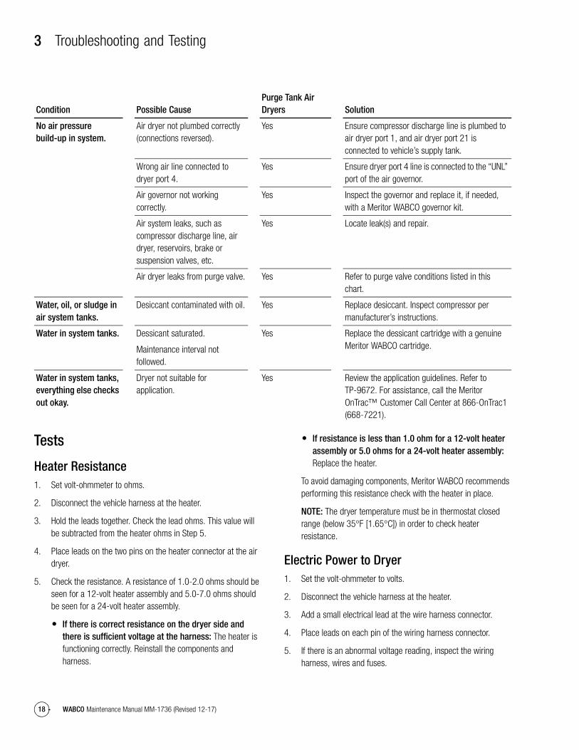
Tests
Heater Resistance1. Set volt-ohmmeter to ohms.
2. Disconnect the vehicle harness at the heater.
3. Hold the leads together. Check the lead ohms. This value will be subtracted from the heater ohms in Step 5.
4. Place leads on the two pins on the heater connector at the air dryer.
5. Check the resistance. A resistance of 1.0-2.0 ohms should be seen for a 12-volt heater assembly and 5.0-7.0 ohms should be seen for a 24-volt heater assembly.
� If there is correct resistance on the dryer side and there is sufficient voltage at the harness: The heater is functioning correctly. Reinstall the components and harness.
� If resistance is less than 1.0 ohm for a 12-volt heater assembly or 5.0 ohms for a 24-volt heater assembly: Replace the heater.
To avoid damaging components, Meritor WABCO recommends performing this resistance check with the heater in place.
NOTE: The dryer temperature must be in thermostat closed range (below 35°F [1.65°C]) in order to check heater resistance.
Electric Power to Dryer1. Set the volt-ohmmeter to volts.
2. Disconnect the vehicle harness at the heater.
3. Add a small electrical lead at the wire harness connector.
4. Place leads on each pin of the wiring harness connector.
5. If there is an abnormal voltage reading, inspect the wiring harness, wires and fuses.
No air pressure build-up in system.
Air dryer not plumbed correctly (connections reversed).
Yes Ensure compressor discharge line is plumbed to air dryer port 1, and air dryer port 21 is connected to vehicle’s supply tank.
Wrong air line connected to dryer port 4.
Yes Ensure dryer port 4 line is connected to the “UNL” port of the air governor.
Air governor not working correctly.
Yes Inspect the governor and replace it, if needed, with a Meritor WABCO governor kit.
Air system leaks, such as compressor discharge line, air dryer, reservoirs, brake or suspension valves, etc.
Yes Locate leak(s) and repair.
Air dryer leaks from purge valve. Yes Refer to purge valve conditions listed in this chart.
Water, oil, or sludge in air system tanks.
Desiccant contaminated with oil. Yes Replace desiccant. Inspect compressor per manufacturer’s instructions.
Water in system tanks. Dessicant saturated.
Maintenance interval not followed.
Yes Replace the dessicant cartridge with a genuine Meritor WABCO cartridge.
Water in system tanks, everything else checks out okay.
Dryer not suitable for application.
Yes Review the application guidelines. Refer to TP-9672. For assistance, call the Meritor OnTrac™ Customer Call Center at 866-OnTrac1 (668-7221).
Condition Possible CausePurge Tank Air Dryers Solution
3 Troubleshooting and Testing
19WABCO Maintenance Manual MM-1736 (Revised 12-17)
Leak Test1. Drain air from all system tanks.
2. Close reservoir draincocks.
3. Start the vehicle. Allow air system pressure to build while engine idles.
4. When the system reaches cut-out pressure there will be a purge, or strong blast of air, followed by a mild flow which will last 10-45 seconds.
5. Shut off the engine.
6. Apply a soap solution to each connection that contains pressurized air. Check the connections to see if soap solution bubbles.
No Soap Bubbles: Connections are sealed correctly.
Soap Bubbles Appear: Connections are NOT sealed correctly.
To Repair Incorrectly Sealed Connections
1. Drain all reservoirs.
2. Remove leaking connection.
3. Inspect the connectors and ports for damaged threads or cracks. Replace if necessary.
4. Apply pipe sealant to the connection.
5. Repeat leak test until all connections are sealed.
Air Pressure Checks
NOTE: When checking air pressure during these tests, do not rely on cab air gauges for accurate readings. Install a calibrated air gauge, accurate to within one psi (7 kPa), in the secondary air tank to determine if air pressure is within the required ranges.
Operational Test for System Saver Series Air Dryers1. Check compressor loaded and unloaded cycle.
When the compressor is in the loaded cycle, air pressure will build to approximately 120-140 psi (827-965 kPa) (cut-out pressure). When the compressor reaches the unloaded cycle, the air dryer will purge, initiating regeneration of the air dryer.
2. Verify that there is no visible pressure drop in the supply and secondary tanks during regeneration. If there is a visible pressure drop, perform a check valve leak test on the system check valves.
4 Appendix I — Glossary
20 WABCO Maintenance Manual MM-1736 (Revised 12-17)
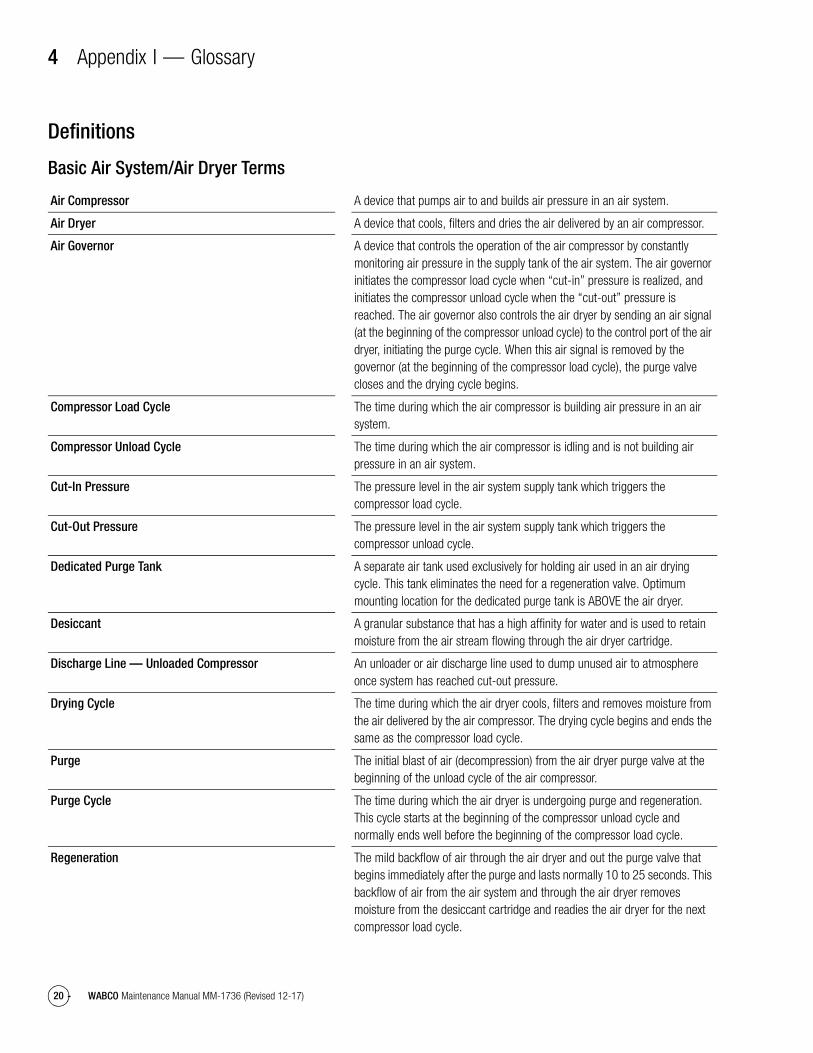
4 Appendix I — GlossaryDefinitions
Basic Air System/Air Dryer Terms
Air Compressor A device that pumps air to and builds air pressure in an air system.
Air Dryer A device that cools, filters and dries the air delivered by an air compressor.
Air Governor A device that controls the operation of the air compressor by constantly monitoring air pressure in the supply tank of the air system. The air governor initiates the compressor load cycle when “cut-in” pressure is realized, and initiates the compressor unload cycle when the “cut-out” pressure is reached. The air governor also controls the air dryer by sending an air signal (at the beginning of the compressor unload cycle) to the control port of the air dryer, initiating the purge cycle. When this air signal is removed by the governor (at the beginning of the compressor load cycle), the purge valve closes and the drying cycle begins.
Compressor Load Cycle The time during which the air compressor is building air pressure in an air system.
Compressor Unload Cycle The time during which the air compressor is idling and is not building air pressure in an air system.
Cut-In Pressure The pressure level in the air system supply tank which triggers the compressor load cycle.
Cut-Out Pressure The pressure level in the air system supply tank which triggers the compressor unload cycle.
Dedicated Purge Tank A separate air tank used exclusively for holding air used in an air drying cycle. This tank eliminates the need for a regeneration valve. Optimum mounting location for the dedicated purge tank is ABOVE the air dryer.
Desiccant A granular substance that has a high affinity for water and is used to retain moisture from the air stream flowing through the air dryer cartridge.
Discharge Line — Unloaded Compressor An unloader or air discharge line used to dump unused air to atmosphere once system has reached cut-out pressure.
Drying Cycle The time during which the air dryer cools, filters and removes moisture from the air delivered by the air compressor. The drying cycle begins and ends the same as the compressor load cycle.
Purge The initial blast of air (decompression) from the air dryer purge valve at the beginning of the unload cycle of the air compressor.
Purge Cycle The time during which the air dryer is undergoing purge and regeneration. This cycle starts at the beginning of the compressor unload cycle and normally ends well before the beginning of the compressor load cycle.
Regeneration The mild backflow of air through the air dryer and out the purge valve that begins immediately after the purge and lasts normally 10 to 25 seconds. This backflow of air from the air system and through the air dryer removes moisture from the desiccant cartridge and readies the air dryer for the next compressor load cycle.

5 Appendix II — Application Information
21WABCO Maintenance Manual MM-1736 (Revised 12-17)
5 Appendix II — Application InformationHazard Alert MessagesRead and observe all Warning and Caution hazard alert messages in this publication. They provide information that can help prevent serious personal injury, damage to components, or both.
WARNINGTo prevent serious eye injury, always wear safe eye protection when you perform vehicle maintenance or service.
Recommendations
NOTE: For complete installation and operating requirements, refer to TP-9672, Air Dryer Application Guidelines. To obtain this publication, refer to the Service Notes page on the front inside cover of this manual.
� Compressor discharge line should have a continual downhill run to the air dryer. There should be no water traps (low points or kinks) in the line before or after the dryer.
� Mount air dryer so that there is no direct splash or spray from a wheel.
� For maximum operating efficiency, mount dedicated purge tank ABOVE the air dryer.
� Keep air dryer at least 12-inches (305 mm) from any heat-producing sources like exhaust manifolds or pipes, transmissions, etc.
� Make sure there are no valves or other devices in the dryer-to-supply-tank line to prohibit or restrict the flow of air back from the supply tank to the air dryer.
� Feed purge valve by a direct line from the air governor.
Operating Environment
Discharge Line:
� Diameter from compressor to air dryer
5/8-inch (15.875 mm) ID minimum for 25.5 cfm and under
3/4-inch (19.05 mm) ID minimum for over 25.5 cfm
IMPORTANT NOTE: Line size and fittings must comply with the compressor manufacturer’s guidelines for backpressure and peak pressure.
� Length from compressor to air dryer
Determined by temperature of air at the inlet port of the air dryer. At normal vehicle operating temperature, the combination of length or increased diameter must be sufficient to keep temperature BELOW 175°F (80°C).
Operating Parameter Requirement
Temperature (ambient operating range)
−40°F to 175°F (−40°C to 80°C)
Electrical Power (for heater and solenoid/timer power)
12 or 24 volts available
Thermostat Range (On/Off temp)
45°F, 86°F (7°C, 30°C)
5 Appendix II — Application Information
22 WABCO Maintenance Manual MM-1736 (Revised 12-17)
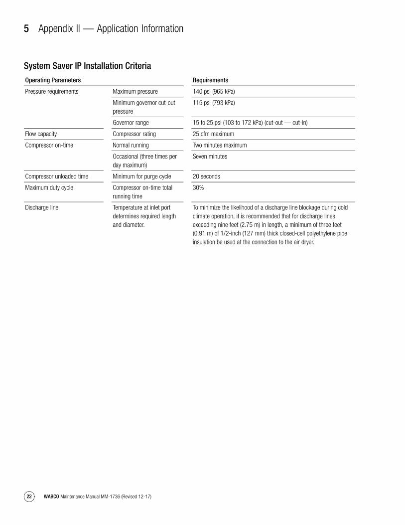
System Saver IP Installation CriteriaOperating Parameters Requirements
Pressure requirements Maximum pressure 140 psi (965 kPa)
Minimum governor cut-out pressure
115 psi (793 kPa)
Governor range 15 to 25 psi (103 to 172 kPa) (cut-out — cut-in)
Flow capacity Compressor rating 25 cfm maximum
Compressor on-time Normal running Two minutes maximum
Occasional (three times per day maximum)
Seven minutes
Compressor unloaded time Minimum for purge cycle 20 seconds
Maximum duty cycle Compressor on-time total running time
30%
Discharge line Temperature at inlet port determines required length and diameter.
To minimize the likelihood of a discharge line blockage during cold climate operation, it is recommended that for discharge lines exceeding nine feet (2.75 m) in length, a minimum of three feet (0.91 m) of 1/2-inch (127 mm) thick closed-cell polyethylene pipe insulation be used at the connection to the air dryer.

WABCO Vehicle Control Systems2135 West Maple Road Printed in USATroy, MI 48084-7121866-OnTrac1 (668-7221) Copyright 2017 Revised 12-17meritorwabco.com WABCO, Inc. Maintenance Manual MM-1736 (16579)


