Mi14-34D / Page /14 1 MAINTENANCE INFORMATION Mi14-34D DATE : MAY 2014 SECTION: 23 - Accessories SUBJECT : PREVOST AWARE ADAPTIVE CRUISE BRAKING (ACB) FLR20 & FLR21 RADAR SENSOR ALIGNMENT THIS MAINTENANCE INFORMATION SUPERSEDES PREVIOUS VERSION. REVISION D Added: FLR21. APPLICATION Model VIN All Equipped with Prevost AWARE Adaptive Cruise Braking system From H3 Series: 2PCVS3493EC712660 incl. X3 Series: 2PCG33496EC735694 incl. DESCRIPTION Prevost AWARE Adaptive Cruise Braking (ACB) is an optional cruise control that adds an additional mode of operation to conventional speed controls, familiar to most drivers of passenger cars. This mode is called distance control. Distance control adjusts the speed of the vehicle to maintain a constant following interval (distance) to the vehicle ahead. Using a radar sensor mounted to the front bumper, the ACB system measures the distance between the coach and the forward vehicle. If the radar sensor becomes misaligned (or any other system problem is detected) a pop-up message will show on the DID to notify the driver that service is needed. If a radar fault condition appears, one of the following pop-up messages will show in the DID. ACB RADAR MISALIGNMENT ACB RADAR DATA LINK FAILURE ACB RADAR FAULT ACB RADAR BLOCKED The first step to go through when a customer complains about false alarms or bad system performance is to check the radar sensor alignment. NOTE The maximum radar range is approximately 500 feet (150 meters). Rain, snow, fog, ice and other severe weather conditions may affect the performance of the ACB system and shorten radar range. Should the radar sensor be blocked with ice, snow or other foreign matter, the
THIS MAINTENANCE INFORMATION SUPERSEDES PREVIOUS VERSION. REVISION D Added: FLR21.
APPLICATION
Model VIN
All
Equipped with Prevost AWARE Adaptive Cruise Braking system
From
H3 Series: 2PCVS3493EC712660 incl.
X3 Series: 2PCG33496EC735694 incl.
DESCRIPTION
Prevost AWARE Adaptive Cruise Braking (ACB) is an optional cruise control that adds an additional mode of operation to conventional speed controls, familiar to most drivers of passenger cars. This mode is called distance control. Distance control adjusts the speed of the vehicle to maintain a constant following interval (distance) to the vehicle ahead. Using a radar sensor mounted to the front bumper, the ACB system measures the distance between the coach and the forward vehicle.
If the radar sensor becomes misaligned (or any other system problem is detected) a pop-up message will show on the DID to notify the driver that service is needed.
If a radar fault condition appears, one of the following pop-up messages will show in the DID.
ACB RADAR MISALIGNMENT ACB RADAR DATA LINK FAILURE
ACB RADAR FAULT ACB RADAR BLOCKED
The first step to go through when a customer complains about false alarms or bad system performance is to check the radar sensor alignment.
NOTE
The maximum radar range is approximately 500 feet (150 meters). Rain, snow, fog, ice and other severe weather conditions may affect the performance of the ACB system and shorten radar range. Should the radar sensor be blocked with ice, snow or other foreign matter, the
Mi14-34D / Page /14
2
pop-up message ACB RADAR BLOCKED will show on the DID.
The ACB radar sensor is pre-aligned at the factory and no adjustment should be needed. It will not function properly if misaligned after a collision. Information may appear on the DID to let you know if the sensor is misaligned. Realigning the radar sensor requires a qualified technician, the radar sensor alignment tool and the present procedure.
MATERIAL NEEDED
CANADA: adjustment tool #685592 (for FLR20 & FLR21 radar sensor). See the image below for the list of components.
USA: adjustment tool kit #7770168 (for FLR20 & FLR21 radar sensor): See the image below for the list of components.
Park vehicle safely, apply parking brake, stop engine and set battery master switch(es) to the OFF position prior to working on the vehicle.
Part 1 CHECKING MISALIGNMENT VALUE USING BENDIX ACom SOFTWARE NOTE: part 1 is optional, you can start with part 2 if ACom is not available
1. On Google, search for « Bendix ACom diagnostics software ».
2. Download the latest version of Bendix ACom Diagnostics® software on your laptop.
Mi14-34D / Page /14
3
3. Launch Bendix ACom Diagnostics®.
4. Select Wingman CAN TP20 and then click on Start with ECU.
Fig.1
5. Select your type of connection (USB-Link) and then click on Open.
Fig.2
6. To check the Misalignment Value, select Controller Configuration.
If the Misalignment Value is within -0.8deg and +0.8deg, no alignment is necessary.
In this case, refer to TROUBLESHOOTING at the enof this document to help determine the cause of potential issues.
ALIGNMENT VALUE RANGE
No Adjustment Needed if: -0.8 deg ≤ Misalignment Value ≤ +0.8 deg
Fig.3
Re-align the radar sensor vertically and horizontally if:
The system seems to track or warn on vehicles in adjacent lanes. The cruise control is not available and the ACB system telltale is illuminating steady in red and
the following message shows in the DID: ″ACB RADAR MISALIGNMENT″. The system seems to not "see" as far as it “used to”, or warn on many more overhead
bridges/signs than previously.
Mi14-34D / Page /14
4
Part 2 PREPARATION
7. Park the coach on a level surface. The suspension must be at normal ride height.
8. H3 Series: Open the reclining bumper and install the steel clip (#688078) over the radar sensor (fig.4 & 5). Steel clip must lean flat on the radar sensor.
9. H3 Series: Close reclining bumper.
FIG.4 : STEEL CLIP #688078
FIG.5 : H3 SERIES – STEEL CLIP INSTALLED ON RADAR SENSOR
10. X3 Series: Open the reclining bumper and remove the radar sensor access panel (fig.6).
Mi14-34D / Page /14
5
FIG.6 : X3 SERIES - RADAR ACCESS PANEL
11. X3 Series: Install the steel clip (#688078) over the radar sensor (fig.7). Steel clip must lean flat on the radar sensor.
12. X3 Series: Close reclining bumper.
FIG.7
Part 3 VERTICAL ALIGNEMENT USING DIGITAL INCLINOMETER
13. Press the digital angle gauge ON/OFF button.
Follow the manufacturer’s instructions if needed.
FIG.8
14. Set the digital inclinometer flat on a horizontal baggage compartment member. Place the digital inclinometer as shown on figure 9.
15. Press the ZERO button to set the gauge to 0.0°. LCD display will show 0.0°.
FIG.9
Mi14-34D / Page /14
6
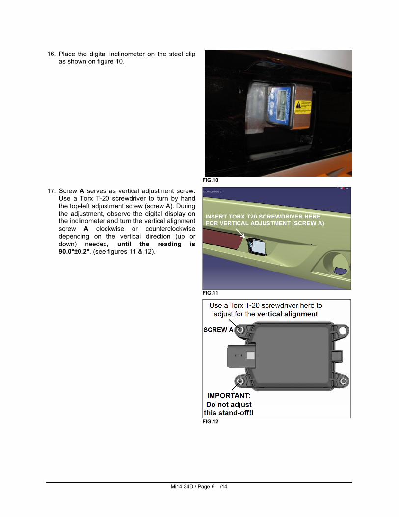
16. Place the digital inclinometer on the steel clip as shown on figure 10.
FIG.10
17. Screw A serves as vertical adjustment screw. Use a Torx T-20 screwdriver to turn by hand the top-left adjustment screw (screw A). During the adjustment, observe the digital display on the inclinometer and turn the vertical alignment screw A clockwise or counterclockwise depending on the vertical direction (up or down) needed, until the reading is 90.0°±0.2°. (see figures 11 & 12).
FIG.11
FIG.12
Mi14-34D / Page /14
7
Part 4 HORIZONTAL (lateral) ADJUSTMENT
18. On the bumper, define two reference points located vertically from the headlamps and at the same height as shown on figures 13 & 14. Later in this procedure, the distance between the bumper surface at these reference points and the laser bean will be measured and then adjusted to be equal on both sides.
FIG.13
FIG.14
Mi14-34D / Page /14
8
19. Remove the digital inclinometer from the steel clip.
20. Passing through the opening in the bumper, fix the alignment tool on the steel clip using the magnetic mounts at the end of the three extensions (fig.15).
FIG.15
21. Turn on each laser and select the flat beam type.
22. Using a measuring tape, measure distance between the laser beam and the bumper at the reference point. For a perfect alignment, this measure should be equal on both sides.
The radar horizontal adjustment is within tolerances if the difference between both measurements does not exceed 19/32″ (15mm)
FIG.16
23. Screw B serves as horizontal adjustment (lateral) screw (fig.17 & 18). Use a Torx T-20 screwdriver to turn by hand the lower-right adjustment screw (screw B). Turn screw B clockwise or counterclockwise depending on direction needed in order to have the same measurement on both sides preferably.
FIG.17
FIG.18
Mi14-34D / Page /14
9
Part 5 ROAD TEST
24. Perform a 30 minutes road test to evaluate the ACB behavior.
FOR FURTHER DETAIL ABOUT TROUBLESHOOTING FLR20 RADAR SENSOR ISSUES, CONSULT « BENDIX SD-61-4960 WINGMAN ADVANCED FLR20 SENSOR ».
Mi14-34D / Page /14
10
TROUBLESHOOTING
TROUBLESHOOTING BASICS
QUESTIONS TO DRIVER NEXT STEPS Have the driver run the Power-Up Self-Test.
Power-up Self-Test This is a self-diagnostic check, to determine if the system operation is normal. 1. Park the vehicle. Power off. 2. Put the key into the ignition, and turn to the “ignition power”
position. 3. Toggle the cruise control switch at least once, and leave it in the
“on” position. 4. Start the vehicle, but do not drive away. Note that if the cruise control is in the “off” position, or if the vehicle is moving, this test will not run. 5. The self-test will start after 15 seconds, and takes approximately
five (5) seconds to complete.
To repeat a second self-test, turn the ignition OFF then repeat procedure above. Note that other vehicle system self-tests, e.g. the ABS “chuff” test, may run during the initial 15 seconds after ignition “ON”. As the ACB system self-test runs, the driver should hear a short set of beeps. The test checks the engine, transmission, and brake systems to make sure they are communicating. In addition, depending on the vehicle, the test may briefly display a distance alert message and/or cause the Forward Vehicle Detected icon in the instrument cluster to illuminate; this is normal.
Does the driver hear a long warning beep?
If no problem is found and the test is passed, no additional beeps/lamps will be displayed nor will a trouble code be set. If the system has found an issue that will prevent it from functioning properly, a long warning beep will sound to alert the driver, and a Diagnostic Trouble Code (DTC) will be logged in the system (typically with a message in the DID). Look for Diagnostic Trouble Code (DTC) using Bendix ACom software. For descriptions of all DTCs, see Section 4.3: Diagnostic Trouble Codes in « BENDIX SD-61-4960 WINGMAN ADVANCED FLR20 SENSOR ».
Have the driver describe the system behavior that they believe shows it is not working properly.
When diagnosing the system, especially in cases where there are no diagnostic trouble codes logged, find out which part of the system behavior appears to be operating improperly.
Mi14-34D / Page /14
11
NARROWING DOWN THE PROBLEM Use the questions found in the table below to help assess if the ACB system is not performing correctly. Be sure to have a thorough understanding of the system’s normal behavior; this will reduce the troubleshooting time. The table provides a guide to basic troubleshooting questions and possible corrective actions. Consult « BENDIX SD-61-4960 WINGMAN ADVANCED FLR20 SENSOR » service literature for more details. QUESTION NEXT STEPS Alignment Problems Is the radar sensor mounting location (bumper or cross member) damaged? • Does the system seem to lose, or “not hold on to,” the forward vehicle when going around curves? • Does the system seem to warn on vehicles in adjacent lanes? • Are there false alerts when passing other vehicles? • Does the system seem to warn late when another vehicle cuts in front of the truck? • Does the system seem to not "see" as far as it “used to”, or warn on many more overhead bridges/ signs than previously? • Does the system seem to be inconsistent when tracking forward vehicles?
Re-align the radar sensor vertically and laterally.
Blocked Radar Sensor Issues Is mud, ice, or snow covering the radar sensor ? Is anything blocking the view of the radar sensor ?
Clean the radar sensor front surface immediately. Remove anything blocking the radar sensor then power cycle and read any remaining trouble codes. If the vehicle's cruise control is set and the radar sensor is blocked by ice, snow, mud, tampering, etc. so that it cannot "see" a forward vehicle, the ACB system may log a diagnostic trouble code (DTC). After the blockage is removed, the DTC will clear automatically when the vehicle’s ignition is cycled. Add a visual check of the radar sensor for blockage to the driver’s pre-trip inspection checklist.
Potential False Warnings Do false alerts seem to happen in construction zones or going under bridges?
Several road scenarios have a tendency to cause false warnings, including construction zones and bridges. Unless these false warnings are frequent, the system is likely reacting normally. The driver should not set the cruise control in construction zones. If driver complaints persist, continue asking questions to more narrowly define the driving condition presenting the problems. Review proper operating conditions in the operator's manual.
Mounting Problems Is the radar sensor mounting location (bumper or cross-member) damaged?
Re-align the radar sensor vertically and laterally. Use the following procedures: • Inspect the radar mounting. A solid mounting surface is necessary in order to hold the alignment. If the bumper or mounting cross-member is
Mi14-34D / Page /14
12
• Does the system seem to not "see" as far as it “used to”, or warn on many more overhead bridges/signs than previously?
damaged, replace it first, then align the radar sensor. Consult « BENDIX SD-61-4960 WINGMAN ADVANCED FLR20 SENSOR ». • Appendix B1 - Go to Appendix B1 and use the flowchart to find out the procedure needed. Follow the actions directed in the procedure and align the radar. • Appendix B4 - Check the vertical alignment and adjust if needed.
Does the mounting bracket look damaged or tampered with?
Other than expected surface scratches or some discoloration over time, there should be no visible damage to the radar sensor bracket assembly. If so, realign the radar sensor vertically and laterally. If radar sensor alignment cannot be held in place, the bracket assembly must be replaced. Verify the bumper is not damaged. The Radar Sensor Mounting - The radar sensor needs a solid mounting surface in order to hold the alignment. If the bumper or mounting cross-member is damaged, replace it first, then align the radar sensor.
Other questions Has the system worked properly in the past and is not working correctly now?
This is a good indication that something has changed; review the questions listed above with the driver to further diagnose the problem.
Does the mounting bracket look damaged or tampered with?
Other than expected surface scratches or some discoloration over time, there should be no visible damage to the radar sensor bracket assembly. If so, realign the radar sensor vertically and laterally. If radar sensor alignment cannot be held in place, the bracket assembly must be replaced. Verify the bumper is not damaged. • Check the Vertical Alignment (6.07) and adjust if needed. • Check the Lateral Alignment (6.09) and adjust if needed. The Radar Sensor Mounting - The radar sensor needs a solid mounting surface in order to hold the alignment. If the bumper or mounting cross member is damaged, replace it first, then align the radar sensor.
With cruise control set, does the system consistently apply the foundation brakes when a forward vehicle slows?
This is normal operation. Continue asking the driver questions to determine if the radar system interventions are not the expected ACB system behavior. If the radar system interventions are not typical, the radar sensor may be misaligned. • Inspect the radar mounting. A solid mounting surface is necessary in order to hold the alignment. If the bumper or mounting cross-member is damaged, replace it first, then align the radar sensor. Consult « BENDIX SD-61-4960 WINGMAN ADVANCED FLR20 SENSOR ». • Appendix B1 - Go to Appendix B1 and use the flowchart to find out the procedure needed. Follow the actions directed in the procedure and align the radar. • Appendix B4 - Check the vertical alignment and adjust if needed. The service technician will need to check trouble codes as well. Read Section 4.3: Diagnostic Trouble Codes.
Does the system seem to disengage after an automatic braking event?
This is normal operation. The driver must set or "resume" the cruise control once again to regain the following distance function.
Does cruise control disengage sometimes when the brakes come on and not at other times?
This is normal operation. When traveling with lightly loaded trailers, or “bobtail”, the adaptive cruise control with braking feature of Wingman Advanced may continue to function even after an automatic brake application. No driver input is needed.
Does the connector or wiring appear damaged?
Wires can become corroded if the radar sensor is not plugged in properly. Clean the connectors on the wire harness, as well as the radar sensor, and reattach. If wires are chafed, replace the wire harness. Also, check for trouble codes using Bendix ACom software. Read Section 4.3: Diagnostic Trouble Codes, and
Does the system generate a diagnostic trouble code going down a grade when using ACB to slow the vehicle, but the code goes away later?
This is normal operation. The adaptive cruise control with braking feature of Wingman Advanced is not intended to be used on grades. Verify there are no diagnostic trouble codes. Proper downgrade driving techniques should be used. Read Section 4.3: Diagnostic Trouble Codes of « BENDIX SD-61-4960 WINGMAN ADVANCED FLR20 SENSOR ».
Does the radar sensor have noticeable damage beyond normal discoloration or surface scratches?
The radar sensor and bracket are very durable. However, if the radar sensor housing or cover is cracked or broken, immediately look for trouble codes via a current version of Bendix ACom and replace the damaged radar sensor. Read Section 4.3: Diagnostic Trouble Codes, and Appendix A.02: Radar Sensor Mounting in « BENDIX SD-61-4960 WINGMAN ADVANCED FLR20 SENSOR ».
OVERVIEW OF POSSIBLE ISSUES
Some customer issues are actually misunderstandings of how the ACB system performs normally. Use the table below to learn the causes of potential issues if the ACB system is not performing correctly. Some issues can be investigated by a visual inspection. Others may cause a diagnostic trouble code (DTC) to be logged: See Section 4.3: Diagnostic Trouble Codes. Consult « BENDIX SD-61-4960 WINGMAN ADVANCED FLR20 SENSOR » for further details. ISSUE DESCRIPTION System familiarity Verify the system functionality. Is it operating normally or not? Drivers
who are unfamiliar with the system may report dissatisfaction over the way it beeps or how it activates the brakes. Use Section 3.0: Introduction to Troubleshooting, Section 4.3: Diagnostic Trouble Codes and Section 3.1: Troubleshooting Basics to verify if the system is functioning normally; then continue.
DTCs caused by temporary operating conditions
Some Diagnostic Trouble Codes (DTCs) indicate a temporary condition and will clear when that condition is no longer present. If these persist, further investigation is warranted. See Section 3.1: Troubleshooting Basics in « BENDIX SD-61-4960 WINGMAN ADVANCED FLR20 SENSOR ».
Radar sensor misalignment
Inspect the front of the vehicle. If (a) it has been damaged, or (b) if the vehicle does not track straight, either of these conditions must be repaired before troubleshooting the ACB system. If there is a DTC set or if the system does not function, the radar sensor may be severely misaligned and the ACB system will not operate until this is corrected. See Appendix B - Bendix Wingman Advanced Radar Alignment in « BENDIX SD-61-4960 WINGMAN ADVANCED FLR20 SENSOR ».
Radar sensor blocked
If the system doesn’t seem to work at all, the radar sensor may possibly be blocked. A DTC will also be set. Visually inspect it, clear the blockage, turn the ignition on and run through a power cycle. See Appendix A3 for more information about radar mounting clearance in « BENDIX SD-61-4960 WINGMAN ADVANCED FLR20 SENSOR ».
Vehicle diagnostic trouble codes (DTCs)
The ACB system will not operate and will set a DTC if any of the following vehicle systems also show a DTC: engine, engine cruise, instrument cluster, Bendix® ABS, Bendix® ATC, Bendix® ESP, or transmission. These components must be repaired and cleared of DTCs before troubleshooting the ACB system. (NOTE: Clearing the vehicle DTCs may be the only step needed to reestablish full ACB system functionality. See Section 4.4: Clearing Diagnostic Trouble
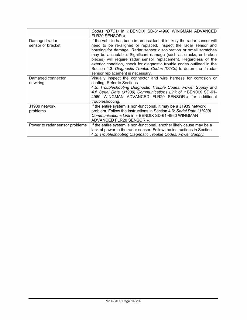
If the vehicle has been in an accident, it is likely the radar sensor will need to be re-aligned or replaced. Inspect the radar sensor and housing for damage. Radar sensor discoloration or small scratches may be acceptable. Significant damage (such as cracks, or broken pieces) will require radar sensor replacement. Regardless of the exterior condition, check for diagnostic trouble codes outlined in the Section 4.3: Diagnostic Trouble Codes (DTCs) to determine if radar sensor replacement is necessary.
Damaged connector or wiring
Visually inspect the connector and wire harness for corrosion or chafing. Refer to Sections 4.5: Troubleshooting Diagnostic Trouble Codes: Power Supply and 4.6 Serial Data (J1939) Communications Link of « BENDIX SD-61-4960 WINGMAN ADVANCED FLR20 SENSOR » for additional troubleshooting.
J1939 network problems
If the entire system is non-functional, it may be a J1939 network problem. Follow the instructions in Section 4.6: Serial Data (J1939) Communications Link in « BENDIX SD-61-4960 WINGMAN ADVANCED FLR20 SENSOR ».
Power to radar sensor problems If the entire system is non-functional, another likely cause may be a lack of power to the radar sensor. Follow the instructions in Section 4.5: Troubleshooting Diagnostic Trouble Codes: Power Supply.