TABLE OF CONTENTS 1. PRINCIPLE OF OPERATION .................................................................................. 2 2. FUNCTION OF THE MANUAL ................................................................................. 2 3. SAFETY INFORMATION ......................................................................................... 2
3.1. Compliance with Instructions in this Manual....................................................... 2 3.2. Installation .......................................................................................................... 2 3.3. Operation & Maintenance .................................................................................. 3
1. PRINCIPLE OF OPERATION Neutral Earthing Resistors (NERs) are employed in AC distribution networks to limit the current that would flow through the neutral star point of a transformer or generator in the event of an earth fault. The rating of NER is chosen so that the fault current is limited to that necessary to protect the system and / or personnel and operate the protection relays within the required time.
The supplied resistor has been designed to meet the requirements of IEEE 32 (and AS2081.5 if referenced) when operated under the conditions specified on the rating plate.
The bank design distributes specified working voltage across the various levels of insulation and is fully tested in accordance with the routine test requirements of IEEE32 1972 before dispatch.
The enclosure provided has sufficient creepage and clearances for the specified voltage. The construction allows for the dissipation of heat generated during a fault without exceeding the temperature specified on the rating plate.
2. FUNCTION OF THE MANUAL The Purchaser/User should comply with the instructions and information given in this manual and ensure that all personnel to be associated with the apparatus supplied under this contract are made familiar with the information contained herein.
DANGERHAZARD OF ELECTRICAL SHOCK,
BURN, OR EXPLOSION
ALL INSTALLATION, OPERATION, MAINTENANCE AND TESTING REFERRED TO IN THIS MANUAL MUST BE CARRIED
OUT BY QUALIFIED PERSONNEL.
ALL POWER SHOULD BE DISCONNECTED PRIOR TO REMOVING COVERS OR OPENING DOORS AND WHERE LIVE CONDUCTORS MAY OTHERWISE BE
EXPOSED.
FAILURE TO OBSERVE THESE PRECAUTIONS MAY RESULT IN DEATH OR SEVERE PERSONAL
INJURY.
3. SAFETY INFORMATION 3.1. Compliance with Instructions
in this Manual The Purchaser/User should comply with the instructions and information given in this manual and ensure that all personnel to be associated with the apparatus supplied under this contract are made familiar with the information contained herein.
3.2. Installation The Purchaser/User should ensure that the apparatus supplied under this contract is correctly installed in a suitable location by technically qualified and competent persons.
Apparatus supplied as loose components, devices or sub-assemblies could, when energized, constitute a safety hazard. The Purchaser/User should ensure that such apparatus is installed in a secure location and that adequate safety information about the installation is provided to all personnel to be associated with it.
3 QF3002_01_NEUTRAL_EARTHING_RESISTOR_IOM
Packing material may be provided to support the resistor banks during transport. This may include red painted brackets and/or timber bracing. This should only be removed once the unit has been securely mounted in its final position.
3.3. Operation & Maintenance The rules for ensuring the safety of personnel can be summarized as follows:-
During normal use ensure that the plant operators:
• Are fully conversant with all controls, particularly those for emergency shutdown.
• Comply with safety warning notices and keep all enclosures shut.
• Are conversant with the information provided, particularly on matters relating to safety.
• Are fully conversant with the apparatus and the system of which it is a part, and recognize the safety hazards which could arise, e.g. back feed.
• Are trained to recognize signs of mal-operation and know what action to take in the event of trouble or difficulty.
During maintenance, testing etc.:
• Ensure that only technically competent and authorized persons are permitted to carry out work.
• Comply with statutory requirements.
• Isolate the apparatus completely (an Isolator is not normally provided with a Neutral Earthing Resistor, before carrying out any work it must be isolated elsewhere) before opening enclosures and prove it to be dead before starting work. Precautions must be taken to ensure that the isolated apparatus cannot become live whilst any work is being carried out.
• Comply with safety working procedures for the safety of operators and of others, including the use of temporary barriers and warning notices.
• Recognize the hazards which can arise when working on live apparatus and take all the necessary precautions.
• Functionally check the apparatus and then mechanically and/or electrically test it in accordance with this manual and good working practice before putting the apparatus back in service.
• Take account of the possibility that the apparatus may have been modified without proper reference to the manufacturer and take extreme caution at all times before, during and after any work is carried out.
• If removable bolted panels are provided, access should be via the bottom panel first. You can then work up to the top panel. Panels are to taken off one at a time. To re-install the panels, start with the top panel and work down to the bottom panel.
If there is any doubt as to the correct and safe method of working then further assistance should be sought from the supplier.
CAUTIONHAZARD OF BURN, OR FIRE
DURING NORMAL SERVICE, EITHER DUE TO STEADY STATE CURRENT FLOW OR A FAULT
CONDITION, BOTH THE ISSUING AIR TEMPERATURE AND THE ENCLOSURE SURFACE TEMPERATURE MAY EXCEED 100°C. EQUIPMENT OR COMBUSTIBLE MATERIALS MUST NOT LIE ON THE TOP COVER OF THE ENCLOSURE OR BE IN
CONTACT WITH THE SIDES.
FAILURE TO OBSERVE THESE PRECAUTIONS MAY RESULT IN
FIRE OR PERSONAL INJURY.
QF3002_01_NEUTRAL_EARTHING_RESISTOR_IOM 4
4. INSTALLATION 4.1. Shipping
Fortress Neutral Earthing Resistors are placed, in their normal mounting position, onto a wooden skid and securely fastened with bolts. The units are then covered with plastic wrap to protect the finish and to prevent dirt or moisture build-up that can occur during shipping or storage. Where extra support is needed during shipment, bracing is used inside the enclosure to support the resistor banks. Finally, the units are crated inside a wooden box. All crated resistors are clearly marked with complete information, including customer marks. The finished crate can be handled by forklift.
4.2. Receiving Once received, the crated unit should be unloaded and moved by forklift. At this point, a preliminary inspection of the crate should be made to ensure proper handling was practiced during shipment. It is recommended that the unit remain crated until it reaches the job site to prevent possible damage during transfer.
All crated neutral earthing resistors are suitable for prolonged storage. If the crated unit is to be stored, it should sit horizontally (as shipped). Never store the unit on the sides or top as it could result in damage. Do not stack.
4.3. Installation Upon arrival at site, uncrate the unit and remove the holding bolts, which fasten it to the skid. All units are crated securely, so care should be exercised during crate removal to prevent damage to the enclosure or top mounted bushings.
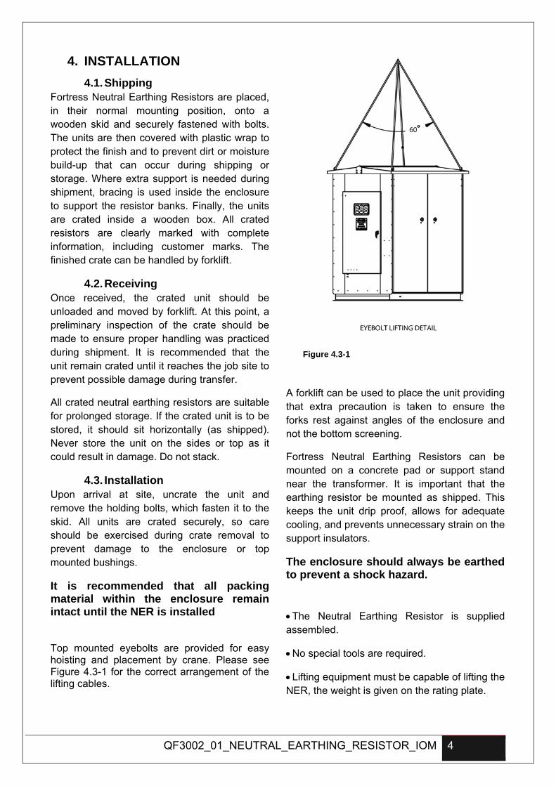
It is recommended that all packing material within the enclosure remain intact until the NER is installed Top mounted eyebolts are provided for easy hoisting and placement by crane. Please see Figure 4.3-1 for the correct arrangement of the lifting cables.
Figure 4.3-1
A forklift can be used to place the unit providing that extra precaution is taken to ensure the forks rest against angles of the enclosure and not the bottom screening.
Fortress Neutral Earthing Resistors can be mounted on a concrete pad or support stand near the transformer. It is important that the earthing resistor be mounted as shipped. This keeps the unit drip proof, allows for adequate cooling, and prevents unnecessary strain on the support insulators.
The enclosure should always be earthed to prevent a shock hazard.
• The Neutral Earthing Resistor is supplied assembled.
• No special tools are required.
• Lifting equipment must be capable of lifting the NER, the weight is given on the rating plate.
5 QF3002_01_NEUTRAL_EARTHING_RESISTOR_IOM
• Place the Neutral Earthing Resistor on the prepared base.
• Take off the removable panel or open the hinged type door to inspect the condition of the resistor.
• Check fixing integrity of the resistor and the insulators.
• Examine for signs of damage during transit i.e. check that the enclosure and support structure are undamaged, that there are no broken insulators and that the resistor elements are secure on their mountings.
• Secure the Neutral Earthing Resistor onto its base. For a concrete base, use expanding bolts or rag bolts which penetrate at least 100mm into solid ground.
• If any internal electrical connections such as cable or bus bar were removed at the factory for protection during transport, ensure that the items are identified and re-installed. Typically connections between the neutral / earth bushings and the resistor banks may be removed and packed securely in the base of the enclosure before shipping.
• Ensure that all electrical connections are tight including connections between individual elements.
• Connect enclosure earth bonding cables as required.
• Drill gland plate as required.
• Connect incoming cable (Resistor Neutral).
• Connect auxiliary wiring.
• Carry out commissioning checks.
• Connect outgoing cable (Resistor Earth).
• Check all enclosure bolts are tight.
4.4. Connections
4.4.1. Neutral Cable The neutral cable from the transformer or generator is to be connected to the designated termination point as shown in the general arrangement drawings.
4.4.2. Earth Cable The Earth cable from earth grid is to be connected to the designated termination point as shown in the general arrangement drawings.
4.5. Tightening Torque Locking and/or tightening of electrical connections using class 8.8 steel bolts should be to the following values:
BOLT SIZE TIGHTENING TORQUE (Nm)
M6 7
M8 17
M10 28
M12 45
M14 65
M16 91
Locking and/or tightening of electrical connections using copper or brass threads should be to the following values:
BOLT SIZE TIGHTENING TORQUE (Nm)
M8 10
M10 18
M12 22
M16 27
QF3002_01_NEUTRAL_EARTHING_RESISTOR_IOM 6
5. COMMISSIONING 5.1. Special Tools & Equipments
No special tools and equipments are required for commissioning
5.2. Commissioning Spares Please note:
• NER has no moving parts to wear out.
• Components manufactured and supplied are done so with the intention of providing continuous service for the full life of the NER.
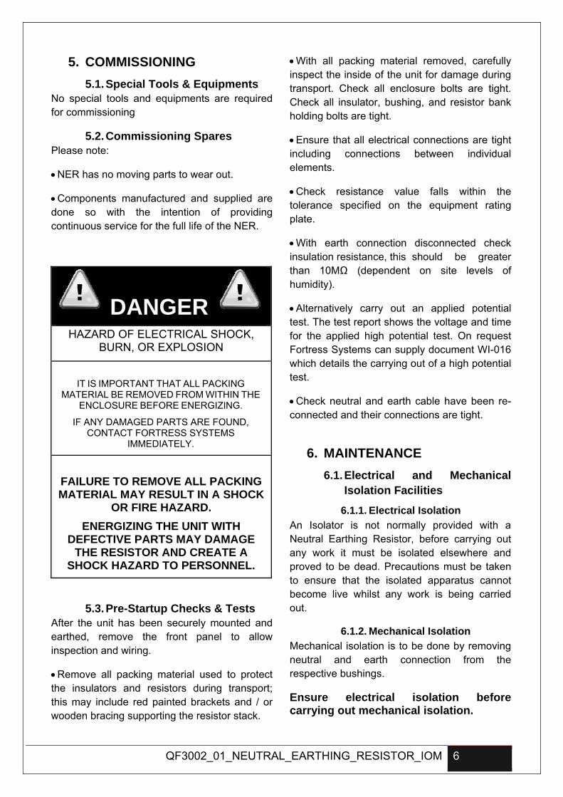
DANGER
HAZARD OF ELECTRICAL SHOCK, BURN, OR EXPLOSION
IT IS IMPORTANT THAT ALL PACKING MATERIAL BE REMOVED FROM WITHIN THE
ENCLOSURE BEFORE ENERGIZING.
IF ANY DAMAGED PARTS ARE FOUND, CONTACT FORTRESS SYSTEMS
IMMEDIATELY.
FAILURE TO REMOVE ALL PACKING MATERIAL MAY RESULT IN A SHOCK
OR FIRE HAZARD. ENERGIZING THE UNIT WITH
DEFECTIVE PARTS MAY DAMAGE THE RESISTOR AND CREATE A
SHOCK HAZARD TO PERSONNEL.
5.3. Pre-Startup Checks & Tests After the unit has been securely mounted and earthed, remove the front panel to allow inspection and wiring.
• Remove all packing material used to protect the insulators and resistors during transport; this may include red painted brackets and / or wooden bracing supporting the resistor stack.
• With all packing material removed, carefully inspect the inside of the unit for damage during transport. Check all enclosure bolts are tight. Check all insulator, bushing, and resistor bank holding bolts are tight.
• Ensure that all electrical connections are tight including connections between individual elements.
• Check resistance value falls within the tolerance specified on the equipment rating plate.
• With earth connection disconnected check insulation resistance, this should be greater than 10MΩ (dependent on site levels of humidity).
• Alternatively carry out an applied potential test. The test report shows the voltage and time for the applied high potential test. On request Fortress Systems can supply document WI-016 which details the carrying out of a high potential test.
• Check neutral and earth cable have been re-connected and their connections are tight.
6. MAINTENANCE 6.1. Electrical and Mechanical
Isolation Facilities
6.1.1. Electrical Isolation An Isolator is not normally provided with a Neutral Earthing Resistor, before carrying out any work it must be isolated elsewhere and proved to be dead. Precautions must be taken to ensure that the isolated apparatus cannot become live whilst any work is being carried out.
6.1.2. Mechanical Isolation Mechanical isolation is to be done by removing neutral and earth connection from the respective bushings.
Ensure electrical isolation before carrying out mechanical isolation.
7 QF3002_01_NEUTRAL_EARTHING_RESISTOR_IOM
6.2. Recommended Inspections & Frequencies
Normally, no maintenance is necessary on a neutral earthing resistor. However periodic inspections for damage are needed to ensure that the resistor is still capable of protecting the system. Damage may occur from lightning, storms, earthquakes, wildlife, overloads or extended service life. It is necessary to ensure that the resistor has not open circuited and that the element (including the incoming bushing) is still properly isolated from earth. It is also prudent to carryout periodic cleaning of the NER especially in high contamination areas.
In high contamination areas inspections every 6 months are recommended. In other areas inspections at 12 month intervals are recommended.
The following procedure is recommended for periodic field inspections.
• De-energise the system being earthed and open the connection between the system neutral and earth resistor. These precautions are recommended to prevent a shock hazard to maintenance personnel and prevent the system from being operated without proper earthing.
• Open the front panel door. This will allow visual inspection of all components.
• Porcelain Insulators & bushings - Remove dirt and check for cracks & disintegrations. A Meggar or HI Pot Test is the most reliable method of ensuring that the insulation is still providing the necessary electrical isolation.
• Resistor Elements – Check that the Resistor Elements are undamaged. Whilst they may show signs of having been very hot, they should not be distorted and the ceramic or mica supports should not be cracked or disintegrating.
• Check the resistor for continuity. An ohmmeter reading made between the neutral and earth
side of the resistor should be within 10% of the name plate value. If the resistance of the element is out by more than 15% of the name plate value, the resistors should be replaced. Any open resistors should be replaced.
Complete nameplate data will be required to obtain replacement parts. • Check all internal connections for tightness. Check wiring for signs of damage from heat or overloads.
• Remove any build up of dust or foreign objects with a soft brush and vacuum cleaner taking care not to leave any foreign objects resting across resistor elements or across any level of insulation.
• Check the enclosure for signs of damage from weather, corrosion or rodents. Replace all side covers removed during inspection and check the mounting bolts for tightness.
For replacement parts or assistance call +61(0)3 9586 4407.
6.3. Dismantling Procedures • Ensure the equipment is isolated and that the remainder of any electrical system it formed part of can function safely without the Neutral Earthing Resistor in circuit.
• Open the front panel door, disconnect and remove incoming cable.
• Remove outgoing earth and bonding earth cables.
• Remove foundation bolts, if the NER is to be removed.