MAJOR OIL PLAYS IN UTAH AND VICINITY QUARTERLY TECHNICAL PROGRESS REPORT Reporting Period Start Date: January 1, 2004 End Date: March 31, 2004 by Thomas C. Chidsey, Jr., Editor and Principal Investigator/Program Manager, Craig D. Morgan, Kevin McClure, Roger L. Bon, J. Wallace Gwynn, Utah Geological Survey; Richard Jarrard, University of Utah; and Richard Curtice, Halliburton Energy Services June 2004 Contract No. DE-FC26-02NT15133 Submitting Organization: Utah Geological Survey 1594 West North Temple, Suite 3110 P.O. Box 146100 Salt Lake City, Utah 84114-6100 Ph.: (801) 537-3300/Fax: (801) 537-3400 Rhonda Jacobs, Contract Manager U.S. Department of Energy National Petroleum Technology Office 1 West 3 rd Street Tulsa, OK 74103-3532
Transcript
MAJOR OIL PLAYS IN UTAH AND VICINITY
QUARTERLY
TECHNICAL PROGRESS REPORT
Reporting Period Start Date: January 1, 2004 End Date: March 31, 2004
by
Thomas C. Chidsey, Jr., Editor and Principal Investigator/Program Manager, Craig D. Morgan, Kevin McClure, Roger L. Bon, J. Wallace Gwynn,
Utah Geological Survey; Richard Jarrard, University of Utah;
1594 West North Temple, Suite 3110 P.O. Box 146100 Salt Lake City, Utah 84114-6100 Ph.: (801) 537-3300/Fax: (801) 537-3400
Rhonda Jacobs, Contract Manager
U.S. Department of Energy National Petroleum Technology Office
1 West 3rd Street Tulsa, OK 74103-3532
DISCLAIMER This report was prepared as an account of work sponsored by an agency of the United States Government. Neither the United States Government nor any agency thereof, nor any of their employees, makes any warranty, express or implied, or assumes any legal liability or responsibility for the accuracy, completeness, or usefulness of any information, apparatus, product, or process disclosed, or represents that its use would not infringe privately owned rights. Reference herein to any specific commercial product, process, or service by trade name, trademark, manufacturer, or otherwise does not necessarily constitute or imply its endorsement, recommendation, or favoring by the United States Government or any agency thereof. The views and opinions of authors expressed herein do not necessarily state or reflect those of the United States Government or any agency thereof. Although this product represents the work of professional scientists, the Utah Department of Natural Resources, Utah Geological Survey, makes no warranty, expressed or implied, regarding its suitability for a particular use. The Utah Department of Natural Resources, Utah Geological Survey, shall not be liable under any circumstances for any direct, indirect, special, incidental, or consequential damages with respect to claims by users of this product.
MAJOR OIL PLAYS IN UTAH AND VICINITY
QUARTERLY
TECHNICAL PROGRESS REPORT
Reporting Period Start Date: January 1, 2004 End Date: March 31, 2004
by
Thomas C. Chidsey, Jr., Editor and Principal Investigator/Program Manager, Craig D. Morgan, Kevin McClure, Roger L. Bon, J. Wallace Gwynn,
Utah Geological Survey; Richard Jarrard, University of Utah;
1594 West North Temple, Suite 3110 P.O. Box 146100 Salt Lake City, Utah 84114-6100 Ph.: (801) 537-3300/Fax: (801) 537-3400
Rhonda Jacobs, Contract Manager U.S. Department of Energy
National Petroleum Technology Office 1 West 3rd Street
Tulsa, OK 74103-3532
US/DOE Patent Clearance is not required prior to the publication of this document.
ABSTRACT
Utah oil fields have produced over 1.2 billion barrels (191 million m3). However, the 13.7 million barrels (2.2 million m3) of production in 2002 was the lowest level in over 40 years and continued the steady decline that began in the mid-1980s. The Utah Geological Survey believes this trend can be reversed by providing play portfolios for the major oil-producing provinces (Paradox Basin, Uinta Basin, and thrust belt) in Utah and adjacent areas in Colorado and Wyoming. Oil plays are geographic areas with petroleum potential caused by favorable combinations of source rock, migration paths, reservoir rock characteristics, and other factors. The play portfolios will include: descriptions and maps of the major oil plays by reservoir; production and reservoir data; case-study field evaluations; locations of major oil pipelines; identification and discussion of land-use constraints; descriptions of reservoir outcrop analogs; and summaries of the state-of-the-art drilling, completion, and secondary/tertiary recovery techniques for each play.
This report covers research activities for the sixth quarter of the project (January 1 through March 31, 2004). This work included analyzing best practices used in the Northern Green River Formation and Deep Overpressured plays of the Uinta Basin. In these two plays, production and ultimate recovery in the Altamont-Bluebell-Cedar Rim field trend leaves a significant amount of oil unproduced. Identifying which beds actually contribute to the production and the role that naturally occurring fractures play in the reservoir remains a major trend-development problem.
Staging acid treatments over smaller (500-foot [150 m]) intervals and greatly increasing the amount of diversion material used has been shown to be effective for maximizing production. A bed-scale completion technique could be effective in older wells nearing depletion where a larger staged completion is no longer economical. Therefore, in older wells it is recommended that treatment of a few individual beds be attempted using a dual packer tool. This way, only the few beds with remaining oil potential are acidized, reducing the size of the treatment needed, and providing more effective stimulation of the beds with remaining potential.
Hydrochloric acid has been, and still is, the recommended treating fluid. Good diversion is also critical to treating the entire interval and a high-enough pumping rate must be maintained to carry the diverting agent. A pumping rate between 8 and 12 bbls per minute (1.3-1.9 m3/min) with proper gelling agents in the fluid will divert the fluid to the perforated intervals, and maintain a reasonable well-head-treating pressure. High-rate hydraulic fracture treatments should be considered on newer wells. Extended hydro-jetting may be a technique to overcome near-wellbore damage caused by drilling and treatment fluids. The dual-burst, thermal-decay time and dipole-shear anisotropy logs are reliable tools for evaluating remaining hydrocarbon potential and fracture density in a cased-hole well that has been producing oil for many years. This type of data can be used to identify potentially productive beds that are not perforated in older wells, eliminate the acidizing of previously perforated beds that have little to no potential, and determine if the acid-fracture treatment is hydraulically fracturing the formation.
As part of technology transfer activities during this quarter, project team members joined Utah Stake Holders Board Members in attending the Uinta Basin Oil and Gas Collaborative Group meeting in Vernal, Utah. An abstract on basin-wide correlation of Green River Formation plays and subplays in the Uinta Basin was accepted by the American
i
Association of Petroleum Geologists, for presentation at the 2004 Rocky Mountain Section meeting in Denver, Colorado. The project home page was updated on the Utah Geological Survey Web site.
ii
CONTENTS ABSTRACT .................................................................................................................................. i EXECUTIVE SUMMARY ......................................................................................................... v INTRODUCTION ....................................................................................................................... 1
BEST PRACTICES, NORTHERN GREEN RIVER FORMATION AND DEEP OVERPRESSURED PLAYS, UINTA BASIN – DISCUSSION AND RESULTS ................... 3
Uinta Basin Province ....................................................................................................... 3 Greater Altamont-Bluebell-Cedar Rim Field Trend ........................................................ 5 Optimal Drilling, Development, and Production Practices ............................................. 8 Log Analyses ..................................................................................................... 10 Casing Designs ................................................................................................... 10 Perforations ........................................................................................................ 11 Stimulation Fluid Treatment .............................................................................. 11 Acid additives ........................................................................................ 11 Diverters ................................................................................................. 13 Fracture gradients ................................................................................... 15 Scale ....................................................................................................... 16 High-rate hydraulic fracture treatments and extended hydro-jetting ..... 17 Correlations ............................................................................................ 17 Dual-Burst Thermal-Decay Time and Dipole-Shear Anisotropy Logs ............. 17 High-Paraffin Crude ........................................................................................... 18 Pumps ................................................................................................................. 18 Water Production and Disposal ......................................................................... 20 Hydrogen Sulfide ............................................................................................... 23 Low-Volume Gas Wells .................................................................................... 23 Environmental Issues ......................................................................................... 23
TECHNOLOGY TRANSFER ................................................................................................... 24 CONCLUSIONS AND RECOMMENDATIONS .................................................................... 25 ACKNOWLEDGMENTS ......................................................................................................... 28 REFERENCES .......................................................................................................................... 29
iii
FIGURES Figure 1. Major oil-producing provinces of Utah and vicinity – (A) Paradox Basin, (B) Uinta
Basin, (C) Utah-Wyoming thrust belt ............................................................................. 2 Figure 2. Diagrams showing the generalized depositional setting for Lake Uinta during high
lake levels (A) and low lake levels (B) ................................................................................. 4 Figure 3. Map showing the Uinta Basin and the USGS Deep Uinta Overpressured Continuous
Oil Assessment Unit and the Uinta Green River Conventional Oil and Gas Assessment Unit ....................................................................................................................................... 6
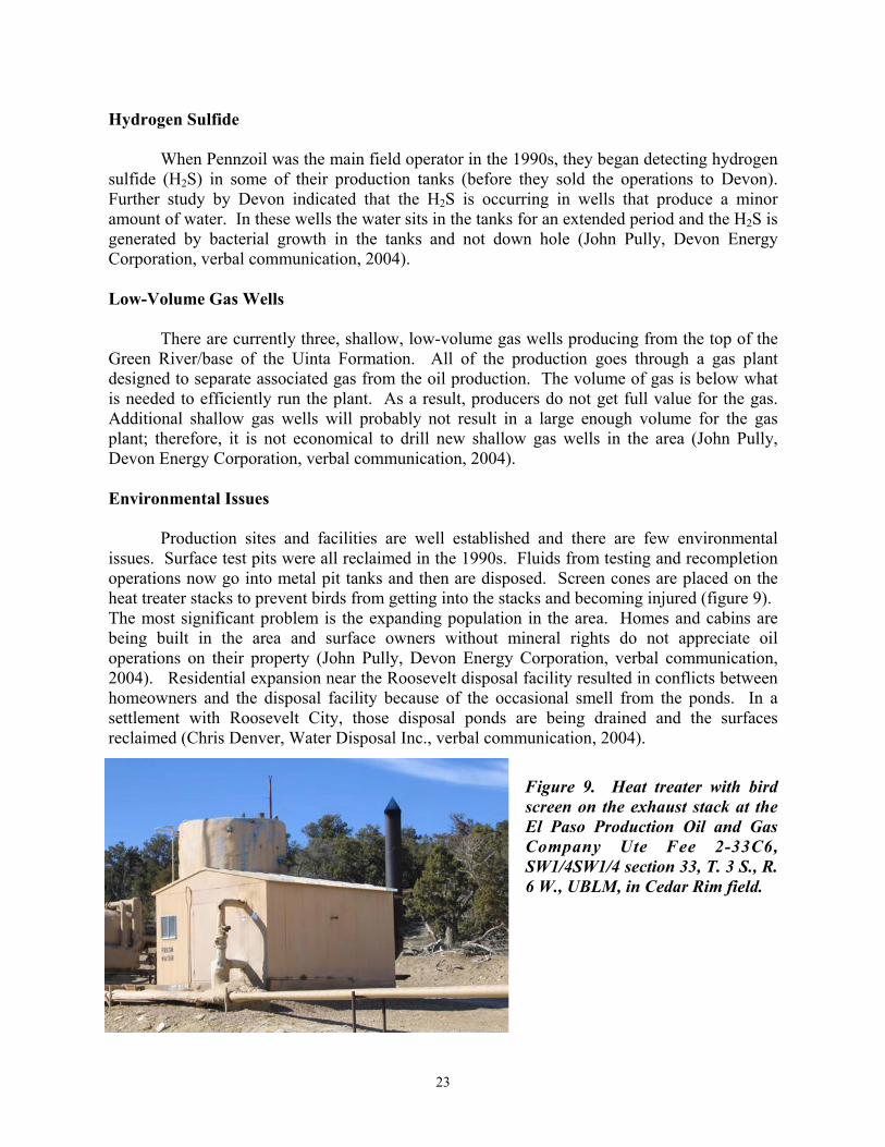
Figure 4. Structure contours on top of the middle marker of the Green River Formation, Bluebell field ................................................................................................................................. 7 Figure 5. Insulated tanks and heat treater in Cedar Rim field ................................................... 18 Figure 6. Pumps commonly used in the greater Altamont-Bluebell-Cedar Rim field trend ..... 19 Figure 7. Location of Uinta Basin commercial water disposal facilities ................................... 21 Figure 8. Commercial water disposal facility – (A) brine evaporation ponds, (B) cement flats used for skimming oil sludge, (C) centrifuge, (D) reclaimation of an evaporation pond ........... 22 Figure 9. Heat treater with bird screen in Cedar Rim field ........................................................ 23
iv
EXECUTIVE SUMMARY
Utah oil fields have produced over 1.2 billion barrels (191 million m3). However, the 13.7 million barrels (2.2 million m3) of production in 2002 was the lowest level in over 40 years and continued the steady decline that began in the mid-1980s. The overall objectives of this study are to: (1) increase recoverable oil from existing field reservoirs, (2) add new discoveries, (3) prevent premature abandonment of numerous small fields, (4) increase deliverability through identifying the latest drilling, completion, and secondary/tertiary recovery techniques, and (5) reduce development costs and risk. To achieve these objectives, the Utah Geological Survey is producing play portfolios for the major oil-producing provinces (Paradox Basin, Uinta Basin, and thrust belt) in Utah and adjacent areas in Colorado and Wyoming. This research is funded by the Preferred Upstream Management Program (PUMPII) of the U.S. Department of Energy, National Petroleum Technology Office (NPTO) in Tulsa, Oklahoma. This report covers research activities for the sixth quarter of the project (January 1 through March 31, 2004). This work included: (1) analyzing best practices used in the Northern Green River Formation and Deep Overpressured plays of the Uinta Basin, and (2) technology transfer activities.
Over 125 fields have been discovered in Utah’s major oil provinces with production from 4300-plus wells. Best practices used in these fields include waterflood, carbon-dioxide flood, gas injection, and horizontal drilling. In the Northern Green River Formation and Deep Overpressured plays of the Uinta Basin, production and ultimate recovery in the Altamont-Bluebell-Cedar Rim field trend leaves a significant amount of oil unproduced. Accurately identifying which beds actually contribute to the production and the role that naturally occurring fractures play in the reservoir remains a major problem for trend development. We recommend that operators in the Bluebell field use geophysical and imaging logs as the primary tool for selecting perforations in new wells, not drilling shows as is commonly done. This should result in a reduction of the number of beds perforated, and more effective treatment. In recompletion of existing wells, cased-hole logs can help identify additional beds to be perforated, and if necessary, identify beds that can be treated individually.
Staging acid treatments over smaller (500-foot [150 m]) intervals and greatly increasing the amount of diversion material used has been shown to be an effective completion technique. Particularly in newer wells, perforating fewer beds and treating shorter gross intervals can result in better completions. Older wells that have been recompleted many times eventually become uneconomical to retreat. In these wells only a minor incremental increase in the oil production rate occurs after treatment because so much of the acid is going into beds that are depleted of oil. A bed-scale completion technique could be effective in older wells nearing depletion where a larger staged completion is no longer economical. Therefore, in older wells we recommend that treatment of a few individual beds be attempted using a dual packer tool. This way, only the few beds with remaining oil potential are acidized, reducing the size of the treatment needed, and providing more effective stimulation of the beds with remaining potential.
Hydrochloric acid has been, and still is, the recommended treating fluid. The tubing should be pickled and reversed out just prior to doing the main acid treatment. Good diversion is also critical to treating the entire interval and a high enough pump rate must be maintained to carry the diverting agent. Higher pumping rates and well-head-treating pressure result in more effective treatments. The higher pressures and pump rates could be indications of good diversion taking place, which allows more of the treatment fluids to enter more of the
v
formation. A pumping rate between 8 and 12 bbls per minute (1.3-1.9 m3/min) with proper gelling agents in the fluid will divert the fluid to the perforated intervals, and maintain a reasonable well-head-treating pressure.
Even successful acid treatments, in most cases, do not maintain adequate linear flow over time, indicating understimulation of the producing formation. Treatments that were hydraulically fractured with a proppant used only a small volume of sand as the propping agent. The ability to do high-rate proppant fracs over large intervals has been proven in other fields in the Uinta Basin and can be done in the Altamont-Bluebell-Cedar Rim field trend. Many older wells may not be suitable for this treatment, but newer wells should be considered candidates for high-rate proppant fracture treatments.
Extended hydro-jetting has not been used, but may be a technique to overcome near-wellbore damage caused by drilling and treatment fluids. Extended hydro-jetting can also be used to provide a small horizontal wellbore into several producing intervals within the same well.
The dual-burst, thermal-decay time and dipole-shear anisotropy logs are reliable tools for evaluating remaining hydrocarbon potential and fracture density in a cased-hole well that has been producing oil for many years. These tools can be used to identify potentially productive beds that are not perforated in older wells, to eliminate the acidizing of previously perforated beds that have little to no potential, and to determine if the acid fracture treatment is hydraulically fracturing the formation.
Currently, the high-paraffin oil produced is stored on location in insulated tanks and the production facilities have a heat treater that keeps the oil above the pour-point temperature. Screen cones are placed on the heat treater stacks to prevent birds from getting into the stacks. Three types of pumps are commonly used in the Altamont-Bluebell-Cedar Rim field trend: (1) the standard pump jack, both center and rear gearbox, (2) the submersible pump and, (3) the rotary flex pump. Water production is a significant part of the operating costs, but a water gathering system using water-injection wells enables disposal of 90 percent of the produced water and represents a significant cost savings. Fluids from testing and recompletion operations now go into metal pit tanks prior to disposal.
As part of technology transfer activities during this quarter, the project team joined Utah Stake Holder Board members in attending the Uinta Basin Oil and Gas Collaborative Group meeting in Vernal, Utah. An abstract on basin-wide correlation of Green River Formation plays and subplays in the Uinta Basin was accepted by the American Association of Petroleum Geologists, for presentation at the 2004 Rocky Mountain Section meeting in Denver, Colorado. The project home page was updated on the Utah Geological Survey Web site.
vi
INTRODUCTION
Project Overview
Utah oil fields have produced over 1.2 billion barrels (bbls) (191 million m3) (Utah Division of Oil, Gas and Mining, 2003). However, the 13.7 million bbls (2.2 million m3) of production in 2002 was the lowest level in over 40 years and continued the steady decline that began in the mid-1980s (Utah Division of Oil, Gas and Mining, 2002). Proven reserves are relatively high, at 283 million bbls (45 million m3) (Energy Information Administration, 2001). With higher oil prices now prevailing, secondary and tertiary recovery techniques should boost future production rates and ultimate recovery from known fields.
Utah’s drilling history has fluctuated greatly due to discoveries, oil price trends, and changing exploration targets. During the boom period of the early 1980s, activity peaked at over 500 wells per year. Sustained high petroleum prices are likely to provide the economic climate needed to entice less high-risk exploration investments (more wildcats), resulting in new discoveries.
Utah still contains large areas that are virtually unexplored. There is also significant potential for increased recovery from existing fields by employing improved reservoir characterization and the latest drilling, completion, and secondary/tertiary recovery technologies. New exploratory targets may be identified from three-dimensional (3D) seismic surveys. Development of potential prospects is within the economic and technical capabilities of both major and independent operators.
The primary goal of this study is to increase recoverable oil reserves from existing field reservoirs and new discoveries by providing play portfolios for the major oil-producing provinces (Paradox Basin, Uinta Basin, and thrust belt) in Utah and adjacent areas in Colorado and Wyoming (figure 1). These play portfolios will include: descriptions (such as stratigraphy, diagenetic analysis, tectonic setting, reservoir characteristics, trap type, seal, and hydrocarbon source) and maps of the major oil plays by reservoir; production and reservoir data; case-study field evaluations; summaries of the state-of-the-art drilling, completion, and secondary/tertiary techniques for each play; locations of major oil pipelines; and descriptions of reservoir outcrop analogs for each play. Also included will be an analysis of land-use constraints on development, such as wilderness or roadless areas, and national parks within oil plays.
Project Benefits
The overall goal of this multi-year project is enhanced petroleum production in the
Rocky Mountain region. Specifically, the project goal will benefit from the following projects: (1) improved reservoir characterization to prevent premature abandonment of numerous small fields in the Paradox and Uinta Basins,
(2) identification of the type of untapped compartments created by reservoir heterogeneity (for example, diagenesis and rapid facies changes) to increase recoverable reserves,
(3) identification of the latest drilling, completion, and secondary/tertiary techniques to increase deliverability,
1
A
C
B
Figure 1. Major oil-producing provinces of Utah and vicinity. A - Oil and gas fields in the Paradox Basin of Utah and Colorado. B - Oil and gas fields in the Uinta Basin of Utah. C - Oil and gas fields, uplifts, and major thrust faults in the Utah-Wyoming thrust belt.
2
(4) identification of reservoir trends for field extension drilling and stimulating exploration in undeveloped parts of producing fairways,
(5) identification of technology used in other identified basins or trends with similar types of reservoirs that might improve production in Utah,
(6) identification of optimal well spacing/location to reduce the number of wells needed to successfully drain a reservoir to reduce development costs and risk, and allow limited energy investment dollars to be used more productively, and
(7) technology transfer to encourage new development and exploration efforts and increase royalty income to the federal, state, local, Native American, and fee owners.
The Utah play portfolios produced by this project will provide an easy-to-use geologic,
engineering, and geographic reference to help petroleum companies plan exploration, land-acquisition strategies, and field development. These portfolios may also help pipeline companies plan future facilities and pipelines. Other users of the portfolios will include petroleum engineers, petroleum land specialists, landowners, bankers and investors, economists, utility companies, manufacturers, county planners, and numerous government agencies.
The results of this project will be transferred to industry and other interested parties through establishment of Technical Advisory and Stake Holders Boards, an industry outreach program, and technical presentations at national and regional professional society meetings. All of this information will be made public through: (1) the Utah Geological Survey (UGS) Web site; (2) an interactive, menu-driven digital product on compact disc; and (3) hard copy publications in various technical or trade journals and UGS publications.
BEST PRACTICES, NORTHERN GREEN RIVER FORMATION AND DEEP OVERPRESSURED PLAYS, UINTA BASIN –
DISCUSSION AND RESULTS
Uinta Basin Province
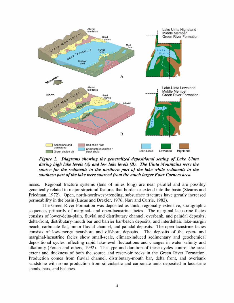
The Uinta Basin is a major depositional and structural basin that subsided and contained large lakes during the early Cenozoic (figure 1B). The Green River and Wasatch Formations, consisting of over 11,000 feet (3600 m) of Paleocene through Eocene sedimentary rocks (Hintze, 1993), accumulated in and around Lakes Uinta and Flagstaff in an intertonguing relationship (figure 2). The northern shore of Lake Uinta was dominated by alluvial fan deltas associated with the Uinta uplift, mud flats, and deep lacustrine deposits. The southern shore was predominantly very broad and flat, and major depositional facies are alluvial, marginal lacustrine, and open lacustrine. These facies changed vertically and laterally due to transgressions and regressions of the shoreline in response to climatic and tectonic-induced rise and fall of the lake. Hydrocarbons are typically trapped in fluvial-deltaic, distributary-channel, bar, and beach sandstone, where they pinch out regionally updip or across subtle anticlinal
3
noses. Regional fracture systems (tens of miles long) are near parallel and are possibly genetically related to major structural features that border or extend into the basin (Stearns and Friedman, 1972). Open, north-northwest-trending, subsurface fractures have greatly increased permeability in the basin (Lucas and Drexler, 1976; Narr and Currie, 1982).
The Green River Formation was deposited as thick, regionally extensive, stratigraphic sequences primarily of marginal- and open-lacustrine facies. The marginal lacustrine facies consists of lower-delta-plain, fluvial and distributary channel, overbank, and paludal deposits; delta-front, distributary-mouth bar and barrier bar/beach deposits; and interdeltaic lake-margin beach, carbonate flat, minor fluvial channel, and paludal deposits. The open-lacustrine facies consists of low-energy nearshore and offshore deposits. The deposits of the open- and marginal-lacustrine facies show small-scale, climate-induced sedimentary and geochemical depositional cycles reflecting rapid lake-level fluctuations and changes in water salinity and alkalinity (Fouch and others, 1992). The type and duration of these cycles control the areal extent and thickness of both the source and reservoir rocks in the Green River Formation. Production comes from fluvial channel, distributary-mouth bar, delta front, and overbank sandstone with some production from siliciclastic and carbonate units deposited in lacustrine shoals, bars, and beaches.
Figure 2. Diagrams showing the generalized depositional setting of Lake Uinta during high lake levels (A) and low lake levels (B). The Uinta Mountains were the source for the sediments in the northern part of the lake while sediments in the southern part of the lake were sourced from the much larger Four Corners area.
4
Alluvial redbed and floodplain deposits that are laterally equivalent to, and intertongue with, the Green River make up the Wasatch (Colton) Formation. The Wasatch Formation was deposited in an alluvial-fluvial environment peripheral to the ancestral lakes. The alluvial-fluvial facies consists of alluvial fan, high mudflat, alluvial-fluvial channel, upper delta plain, and small pond deposits. Most production comes from lenticular, fluvial-alluvial channel and alluvial, overbank sandstone deposits (Fouch, 1975; Ryder and others, 1976). The channel sandstones were deposited by streams flowing southward from the Uinta uplift.
The primary source rocks for the oil and associated gas in the Green River and Wasatch Formations are interbedded, organic-rich, carbonate mudstones, presently at depths of 8500 to 12,500 feet (2800-4200 m) in the north-central part of the basin (Nuccio and others, 1992). Liquid and gas volume changes accompanying hydrocarbon generation, and the low-permeability of the rocks have caused overpressuring and additional fracturing in the basin (Fouch and others, 1992).
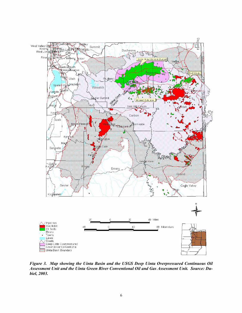
The U.S. Geological Survey (USGS) identifies two assessment units in the Green River Total Petroleum System within the Uinta Basin (Dubiel, 2003): (1) the Deep Uinta Overpressured Continuous Oil Assessment Unit and (2) the Uinta Green River Conventional Oil and Gas Assessment Unit (figure 3). The USGS defines the Deep Uinta Overpressured Continuous Oil Assessment Unit where overpressured (gradient > 0.5 pounds per square inch per foot [psi/ft] [11.3 kPa/m]) source and reservoir rocks occur in the Green River Formation. The overpressuring is located near the basin center, mostly in the Colton Formation and Flagstaff Member of the Green River in the Altamont, Bluebell, and Cedar Rim fields. The > 0.5 psi/ft gradient is encountered as shallow as 8500 feet (2600 m). However, most of the high-volume, overpressured oil production is typically from 12,000 to 14,000 feet (3600-4300 m) in the Flagstaff Member. The Uinta Green River Conventional Oil and Gas Assessment Unit is defined by the distribution of normally pressured oil and gas accumulations in the Green River Formation at depths less than 8500 feet (2600 m) (Dubiel, 2003). The unit overlies the entire area of the Deep Uinta Overpressured Continuous Oil Assessment Unit (figure 3). The Uinta Green River Conventional Oil and Gas Assessment Unit consists entirely of the part of the Green River Formation that overlies the Colton and Wasatch Formations. The dominant sediment source area for the Green River Formation in the Altamont, Bluebell, Cedar Rim, and Red Wash fields was to the north, while the sediment source area for the greater Monument Butte, Duchesne, Brundage Canyon, Sowers, Antelope Creek, and Uteland Butte fields was to the south (figures 1 and 2). As a result, the deposition and the resulting reservoir properties are significantly different between south-sourced and north-sourced depositional systems. We divide the Uinta Green River Conventional Oil and Gas Assessment Unit into two plays: (1) the Southern Green River Formation Uinta Basin Play and (2) Northern Green River Formation Uinta Basin Play. We also divide the Deep Uinta Overpressured Continuous Oil Assessment Unit into two plays: (1) the Overpressured Colton/Flagstaff Play and (2) the Overpressured Lower Green River Play. The greater Altamont-Bluebell-Cedar Rim field trend of the Northern Green River Conventional Uinta Basin and Deep Uinta Overpressured plays is discussed here.
Greater Altamont-Bluebell-Cedar Rim Field Trend
The greater Altamont-Bluebell-Cedar Rim field trend of Duchesne and Uintah Counties, Utah, occurs along a generally contiguous, stratigraphic, updip pinchout on the south-dipping
5
Figure 3. Map showing the Uinta Basin and the USGS Deep Uinta Overpressured Continuous Oil Assessment Unit and the Uinta Green River Conventional Oil and Gas Assessment Unit. Source: Du-biel, 2003.
6
flank of the Uinta Basin (figure 3). The gentle southern regional dip is occasionally interrupted by subtle structural noses (figure 4). Oil production is from multiple, stacked, fluvial-deltaic channel and offshore bar sandstone, and some lacustrine limestone and shale in the upper Green River, lower Green River, and Flagstaff Member/Colton (Wasatch) Formations. The Flagstaff Member/Colton reservoir is an overpressured, basin-centered, oil accumulation controlled by fractures. Typical wells produce from 20 to 50 zones in Altamont and Bluebell reservoirs (Smouse, 1993). These zones are channel sandstone, 3 to 40 feet (1-13 m) thick. The producing Altamont-Bluebell-Cedar Rim field trend extends over a 290,580-acre (117,600 ha) area.
Quartzarenites and litharenites predominate in the north part of the basin. They consist of monocrystalline quartz with chert as the main lithic component (Fouch and others, 1992). Diagenetic effects both reduce and enhance reservoir porosity and permeability. Compaction and authigenic clay formation (illite) have reduced reservoir quality in the Altamont-Bluebell-Cedar Rim field trend (Pitman and others, 1982). Porosity ranges from 2 to 20 percent, averaging 5 percent. Permeability is highly variable ranging from 0.1 up to 1000 millidarcies (md) in fractured zones (Fouch and others, 1992; Smouse, 1993). The drive is solution gas, and the initial water saturation was 10 percent or greater (Smouse, 1993).
The first Green River Formation reservoir was discovered in 1949 at Bluebell field (Roosevelt unit), with the completion of the Humble Oil Ute Tribal No. 1 well, NW1/4SW1/4
Figure 4. Structure contours on top of the middle marker of the Green River Formation, Bluebell field, Duchesne and Uintah Counties, Utah. Datum = mean sea level.
7
section 21, T. 1 S., R. 1 E., Uinta Base Line and Meridian (UBL&M); initial flowing potential was 1633 bbls of oil per day (BOPD) (260 m3/d). The first Wasatch Formation reservoir was discovered in 1970 at Altamont field, with the completion of the Shell Oil Miles No. 1-36A4 well, SW1/4NE1/4 section 35, T. 1 S., R. 4 E., UBL&M; initial flowing potential was 1004 BOPD (160 m3/d). The Altamont-Bluebell-Cedar Rim field area currently has 585 producing (or shut-in) wells (Utah Division of Oil, Gas and Mining, 2003). The well spacing is 320 acres (130 ha). Cumulative production as of December 1, 2003, was 284,238,372 bbls of oil (45,939,901 m3), 481 billion cubic feet of gas (BCFG) (14 BCMG), and over 523 million bbls of water (83 million m3) (Utah Division of Oil, Gas and Mining, 2003). The original, estimated, primary recovery was 316,000,000 bbls of oil (Smouse, 1993).
Ownership in the Altamont-Bluebell-Cedar Rim field trend has changed many times since the trend’s discovery. In 1999, Devon Energy Corporation purchased Pennz Energy’s (formerly Pennzoil) Uinta Basin operations. After assuming ownership of the properties Devon drilled five new wells. Like other operators, Devon found that the second well per section usually had some pressure drainage. This results in marginal to uneconomical wells that only produce about 200,000 bbls (31,800 m3) of oil. Generally about 300,000 bbls (47,700 m3) of oil within a few years is needed to be economical. At current prices, a well can be operated at a rate as low as 10 bbls (2 m3) of oil per day (John Pully, Devon Energy Corporation, verbal communication, 2004).
Devon’s new wells were drilled and completed following standard practice for the area. About 10,000 feet (3300 m) of intermediate casing was set near the top of the Wasatch (Colton) Formation before drilling the potentially overpressured, lower productive interval. Perforation intervals were selected based on drilling shows and gamma-ray and resistivity log values. The wells were completed with an acid stimulation in two 800-foot (270 m) stages (approximately) (John Pully, Devon Energy Corporation, verbal communication, 2004).
Optimal Drilling, Development, and Production Practices
Individual beds in the lower Green River and Wasatch producing interval of the Altamont-Bluebell-Cedar Rim field trend are difficult to evaluate. Fracturing and complex formation-water chemistries make conventional geophysical log analysis highly questionable. Petroleum economics have discouraged open hole and/or production testing of individual beds. Therefore, operators do not clearly understand which beds in any particular well are potentially significant producers, limited producers, water producers, or thief zones. Other field development issues include communication between zones via vertical fractures, high water cuts, and paraffin buildup; these problems necessitate numerous workovers. In addition, water disposal can be an issue if injection wells are not available near remote well sites.
The individual producing beds are difficult to evaluate because fracturing, clay content, rugose hole conditions, and poorly constrained formation-water resistivities make conventional geophysical log analysis difficult. Production testing of individual beds in either cased or open hole can be quite costly because of the potentially large number of beds involved, and therefore is typically not done. As a result, wells are completed in a “shotgun” approach by perforating all the beds that had any show of hydrocarbons while drilling, or on the geophysical well logs, or in neighboring wells. The common practice is to perforate numerous beds over thousands of vertical feet and apply an acid-frac treatment, generally 20,000 gallons (75,700 L) of hydrochloric acid (HCl). This treatment is applied to both clastic and carbonate, fractured and
8
non-fractured beds, over-pressured and normally pressured zones. The gross productive interval in many wells is over 3000 feet (900 m) thick. During the life of a well, new perforations are often added, increasing the net footage treated (Morgan, 2003).
Many operators have begun treating older wells by staging the acid treatments over intervals of about 500 feet (150 m) per stage, and by using much more diverting agent than in the past. This method ensures that the acid is pumped in the perforated beds more effectively and results in fewer perforated beds being bypassed (Reid and others, 1995). Unfortunately, this technique still represents a relatively indiscriminate approach and results in acidizing many beds that may be nonproductive, water productive, or thief zones. Typically, an operator treating a 1500-foot (500-m) interval will treat the lower 500 feet (160 m), move the packer up and treat the middle 500 feet (152 m), and then treat the upper 500-foot (160-m) interval. Ideally, the diversion material plugs the perforations of a stage before moving up hole so only 500-foot (160-m) sections are being treated at a time. To improve completion techniques in the Altamont-Bluebell-Cedar Rim field trend it is necessary to accurately identify productive beds and reduce the number of beds requiring stimulation (Morgan, 2003).
HCl is the most common treatment fluid used in the field trend. Corrosion inhibitors, surfactants, and iron, scale, and clay control additives are commonly used in most, but not all, treatments. The use of diverters is important when trying to treat large intervals so that the fluids flow into as many of the perforated beds as possible. When acid begins to enter a perforation, the flow carries the diverter into the perforation, plugging it off and causing the acid to flow to other perforations. When the acid flows back out of the hole, the diverting agent should come out of the perforation and flow back with the acid. The most commonly used diverters in the Bluebell field are rubber-coated-nylon (RCN) ball sealers and benzoic acid flakes. Rock salt, wax beads, and mothballs have all been used as diverters. Common practice is to use more than one type of diverter in a single treatment (Morgan, 2003).
Devon Energy generally picks new beds to perforate based on drilling shows and favorable gamma ray and resistivity values. They stimulate the new beds with 15 percent HCl plus additives using about 100 gallons (390 L) per foot, using a pumping rate of 5 to 8 bbls (1-2 m3) per minute at a maximum of 9000 psi (62,000 kpa). Sand proppant is occasionally used when treating shallower sandstone beds (typically 9000 feet [3000 m] or less), but cannot be used on the deeper beds due to the higher pressures, which would crush the sand proppant (John Pully, Devon Energy Corporation, verbal communication, 2004).
The following sections summarize the findings of a UGS project titled Increased Oil Production and Reserves from Improved Completion Techniques in the Bluebell Field, Uinta Basin, Utah conducted from 1994 to 1998, funded under the DOE Class I Oil Program (Allison and Morgan, 1996; Morgan, 1997; Deo and Morgan, 1998; and Morgan and Deo, 1999). As part of the study, Halliburton Energy Services Tech Team in Denver, Colorado, analyzed Bluebell field treatment data and completion histories from 67 wells consisting of 246 stimulations (108 different parameters in each treatment). The treatments were performed between August 1968 and November 1994. The total depths (TD) of the wells analyzed varied from 12,314 to 17,419 feet (3753-5309 m). The analysis determined which types of casing and perforating techniques have been used, which types of stimulation treatments have been pumped, which types have been the most effective, and what additives have been used and their effectiveness. The project also included field demonstrations of the recommended techniques in Bluebell field (Morgan, 2003).
9
Log Analyses
Quantitative log analysis is normally the primary method for identifying lithology, porosity, and water saturation of individual beds in order to select the best zones to perforate. However, in Altamont-Bluebell-Cedar Rim field trend, quantitative log analysis is seldom undertaken, for several reasons: (1) poor hole conditions leading to poor-quality logs, (2) inability of standard logs to identify open fractures, and (3) inaccurate water resistivities leading to poor estimates of water saturation. These problems may stem, in part, from (1) the many vintages of logs, (2) the variety of log types, (3) the large numbers of operators (each working with only a few wells), and (4) the use of paper logs rather than digital logs.
The reliability of log-based estimation of percent shale (percent clay), porosity, and water saturation was evaluated, using core plugs and cuttings for ground truth (Allison and Morgan, 1996). The analyses showed (1) log-based determination of percent shale is relatively straightforward (although determination of the non-shale component is non-unique), (2) clean-formation porosity is best determined using an average of neutron and density porosity, and (3) uncertainties in fluid resistivity preclude accurate calculation of water saturation.
Based on core-plug analyses, it was determined that sufficient intergranular permeability for long-term producibility will be found only among nearly shale-free rocks that have porosities greater than 6 percent. Gamma-ray logs are only a moderately good indicator of shale-free rocks; spectral-gamma logs are substantially better. Neutron/density porosity averaging can indicate zones with adequate porosity, but only if rugose hole conditions do not excessively degrade log accuracy and if shaly zones are avoided. Of the many beds typically chosen for completion in an Altamont-Bluebell-Cedar Rim field well, a large number appear to be promising based on overly optimistic porosity determinations, but will have only transient production. Increased attention to two factors, (1) shale-free beds and (2) reliably determined high porosities, will significantly increase the average producibility of zones chosen for completion.
Log-based porosity can be calculated from any of the four standard logs: (1) density, (2) neutron, (3) sonic, or (4) resistivity. For example, in Bluebell field, industry practice is to calculate porosity either by simple averaging of neutron and density porosities or by converting sonic travel time to porosity. The former is preferred if hole conditions are good enough to permit satisfactory neutron and density logging. In unusually rugose holes, a sonic log is run instead to provide porosities.
Uncertainties in fluid resistivity preclude accurate calculations of water saturation; measurements and calculations of the water resistivity are highly variable. The median RW in the Roosevelt Unit area of Bluebell field is 0.74 ohm·meter at 68°F (20°C) and no systematic variation is evident with depth, except for temperature-dependent variations. Casing Designs
Typically, three strings of pipe are set in a deep well drilled in the Altamont-Bluebell-Cedar Rim field trend. The first string is a 9-5/8-inch (24.4 cm) diameter surface pipe, or in some cases 10-3/4-inch (27.3 cm) diameter. The second, intermediate string of pipe is 7- or 7-5/8-inch- (17.8 or 19.4 cm) diameter pipe set from a depth of 9,450 to 13,982 feet (2880-4262 m). The third string is commonly a 5-inch- (12.7 cm) diameter liner weighing 18 pounds per
10
foot (lb/ft [26.8 kg/m]). Occasionally, some 5-1/2-inch- (13.9 cm) and a few 4-1/2-inch- (11.4 cm) diameter strings are set. Typically the depth of the liner is from 12,314 to 17,419 feet (3753-5309 m) and the length varies from 1859 to 5314 feet (567-1620 m). Not all of the wells have liners; seven wells, or 10.4 percent of the wells studied, have no indication that a liner was set.
Perforations
The perforated interval is often quite large. The reported net interval (total footage perforated) varies from 4 to 1310 feet (1.2-399 m), and the gross perforated interval (depth of the lowest perforation minus the depth of the top perforation) varies from 4 to 3009 feet (1.2-917 m). The number of perforations range from four shots to a maximum of 5240 shots. Perforations vary in size from 0.26 to 0.56 inch (0.66-1.42 cm) diameter, the most common being 0.38 inch (0.97 cm) diameter. The density of the perforations varies from one to four shots per foot, the most common being two shots per foot. The depth to the top perforation varies from 8195 to 15,450 feet (2498-4709 m) and the depth to the bottom perforation varies from 9656 to 16,417 feet (2943-5004 m). The average gross perforated interval has the top perforation at 11,350 feet (3460 m) and the bottom perforation at 12,539 feet (3822 m), or an overall average gross perforated interval of 1190 feet (363 m) with 284 perforations. Common practice is to perforate every potentially productive interval at the same time. Historically, the trend has gone from producing a small interval to a larger interval, from a few perforations to many perforations, and from small to large acid treatments. However, improvement in well response over time is questionable (Morgan, 2003). Stimulation Fluid Treatment
HCl is the most common treatment fluid used (90 percent) in the Altamont-Bluebell-Cedar Rim field trend. Most HCl acid treatments had concentrations of 15 percent acid. The other acid treatments also included HCl acid in part. Ninety-eight percent of the treatments studied were pumped using some type of acid, while the remaining 2 percent were proppant treatments. The three proppant treatments tried included the following fluid types: (1) borate cross-linked fluid pumped in the lower Green River reservoir with 100,000 pounds (45,360 kg) of 20/40 mesh sand, (2) gelled oil pumped in the Colton/Flagstaff reservoir with only 2000 pounds (907 kg) of sand and 2000 pounds (907 kg) of glass beads, and (3) oil and water emulsion pumped in the lower Green River reservoir with 24,000 pounds (10,886 kg) of 40/60 mesh sand and 76,000 pounds (34,473 kg) of 20/40 mesh sand. The pumping of acid is still the preferred treatment. However, the response to acid treatments typically decreases over time as the well becomes oil depleted. In the late 1960s, for every gallon (3.8 L) of acid pumped, approximately 10 bbls (1.6 m3) of incremental oil was produced, while the current result is now less than one bbl (0.2 m3) of incremental oil for every gallon (3.8 L) of acid pumped (Morgan, 2003). Acid additives: When a formation is treated with acid to increase production, there is a large arsenal of chemical additives which help to enhance oil production. Typically an acid treatment will contain, at a minimum, the following types of additives: (1) surfactants, (2) corrosion inhibitor, (3) iron control, and (4) some type of clay control. Other additives are available but
11
have a more specific application depending on the problem. There are ten different additive types used which can be categorized according to their effects.
Not all the additive types are used in all treatments, but it is surprising that certain additives were not used on all of the treatments. For instance, corrosion inhibitor is one chemical additive that one would expect to find in all the acid treatments. The primary purpose of corrosion inhibitor is to protect tubular goods and surface equipment from being damaged by acid. Without this additive it is quite possible to damage some tubing or casing in the wellbore, yet this additive was only used in less than half the treatments.
Surfactants are commonly found in most acid systems, but again only a little over half the treatments have used some type of surfactant. The primary use of surfactants is to reduce the surface tension of a liquid to allow it to flow easier and prevent emulsions from forming. They also are used to change the wettability of a formation. The type of surfactants available to the industry has increased over the years, but in some cases the same surfactant package that was used in 1968 is still being used today. However, the data show the surfactant had little to no effect on post-treatment production. Generally, this additive should be left out unless other types and concentrations of surfactant prove to perform better in the future.
Iron control is the second most commonly used additive (used in half the treatments). Formation damage due to iron precipitation has been recognized as a significant problem in wellbores for over 30 years, yet is often ignored. Pyrite, a source of iron in the Green River Formation, was identified in several core samples taken from wells in Bluebell field. However, the most common source of iron is the tubulars in the wellbore. The wellbore tubulars are a constant source of iron, yet operators apparently never take the prudent action of pickling tubulars prior to acidizing. Millscale on new pipe also contains a large amount of iron. One study on millscale which was conducted in new 2-7/8-inch-diameter (7-cm), 6.5 pound/foot (9.7 kg/m) tubing indicated that a minimum of 690 gallons (2610 L) of 15 percent HCl acid could react with millscale in 10,000 feet (3300 m) of tubing. If the iron stayed in solution, the acid would contain 81,360 parts per million (ppm) of total iron. The iron that is present in wellbore tubulars typically is just common rust, but this can severely damage the formation when mobilized during an acid treatment. Ignoring this problem while conducting repeated treatments could damage a formation beyond repair.
Clay control additives are also used in about a third of the treatments. Clay control additives in proper concentration, can prevent swelling and/or migration of clay particles. The most common clays in the Green River Formation are illite-smectite and chlorite-smectite mixed-layered clays, and a minor amount of kaolinite (Allison and Morgan, 1996). Therefore, use of a good clay control additive is recommended when treating the Green River.
Friction reducers are used to reduce the friction pressure loss caused by pumping down small tubulars at high rates. Friction reducers can help maintain the desired pump rate to treat the formation or reduce the number of high-pressure pumps needed. In Bluebell field, the average depth of the tubing is 10,812 feet (3300 m). The rates at which fluids are pumped down 2-7/8-inch-diameter (7-cm) tubing varied from 0.3 bbl per minute (BPM) to 19.5 BPM (0.05-3.1 m3/min). The overall average pumping rate down 2-7/8-inch-diameter (7-cm) tubing is 9.2 BPM (1.5 m3/min). To obtain rates much over 8 BPM (1.3 m3/min) it is necessary to use some type of friction reducer.
Friction reducers in the treating fluids also help mitigate friction pressure loss to allow use of decreased well-head-treating pressure (WHTP). Decreased WHTP lowers the hydraulic horsepower (HHP) needed for increased pumping rates. Although friction reducers do not
12
enhance the acid system, they do affect the placement of the treatment. If acid is pumped at 9 BPM (1.26 MTM) and no friction reducer is used in the acid, the friction pressure loss alone for the average depth of 2-7/8-inch-diameter (7-cm) tubing would be equal to 5400 psi (37,200 kPa). If the acid contained a gelling-agent friction reducer, the friction pressure loss for the same string of tubing would only be 1520 psi (10,480 kPa). By using a gelled acid instead of a non-gelled acid the WHTP would be reduced by 3880 psi (26,750 kPa) at 9 BPM (1.4 m3/min) and the HHP requirement would also be reduced by 856.
Silt suspenders and foaming agents have been used in some treatments. In a few cases the foaming agent appeared in the surfactant category because this additive fits both categories. This type of additive is typically used if a foamed fluid is desired, or if removal of fines is a problem. For instance, if a sandstone is held together by calcium carbonate cement, then the acid will remove the cement and the rock basically falls apart leaving behind fines that will plug pore throats. If plugging of pore throats by fines is a problem, then either this type of additive should be used, or the acid should contain a gelling agent that will maintain enough viscosity in the treatment fluids to carry fines out of the formation during treatment cleanup.
Nitrogen (N2) and carbon dioxide (CO2) are not chemical additives, but are common gases used in the treatments. The use of a gas in a treatment does several things: (1) enhances treatment cleanup, (2) increases the volume of the treatment, and (3) in the case of N2, decreases the hydrostatic pressure during the treatment. One of the advantages of using a gas assist is that well cleanup is faster and sometimes more thorough. A foaming agent is often used in gas-assist treatments resulting in a foamed fluid, which helps in removing fines generated from the acid treatment. One of the disadvantages of using a gas is that it is compressible, making it difficult to determine what type of diverter action is taking place. Gas-assist treatments have not resulted in a significantly better well response compared to the typical acid treatment.
Paraffin buildup is a problem in the Altamont-Bluebell-Cedar Rim field trend and throughout the Uinta Basin, yet only a limited number of treatments have used some type of solvent or paraffin control in the acid system. When solvents were used, the volumes were so small (100 to 1000 gallons [375-3785 L]) that they were probably not effective. When a solvent was used, it was spearheaded in front of all the other fluids and probably only affected one interval, and few active ingredients were left by the time it passed the first perforations.
Acid can only react with a material if it contacts it. Scale is a problem throughout the field trend and is typically layered with paraffin (scale then paraffin or paraffin then scale, similar to rings found in a tree trunk). When an acid, without some type of solvent, comes in contact with layered scale, the chances of reacting with more than one layer of scale is questionable. An acid containing a solvent will remove layers of both scale and paraffin.
Treatment fluids are usually heated prior to being pumped down the hole. This is a good practice and should be continued. Heating the fluids helps prevent paraffin from solidifying and plugging the porosity in the formation. However, only the water phase of the acid is heated and the heat loss when cooler acid is added to the water can be quite substantial. The temperature of the acid solution is typically high enough to prevent solidification of paraffin, but may not be high enough to dissolve paraffin layers in the scaling. Diverters: Good diversion (diverting the treatment fluid into all of the perforations) is needed when attempting to treat large intervals. There have been several types of diverters used in Altamont-Bluebell-Cedar Rim treatments. The most commonly used diverter is 7/8-inch (2 cm)
13
diameter, RCN, ball sealers with a specific gravity (SG) of 1.1 or 1.3, except in older treatments where 1.4 SG balls were used. The number of balls pumped ranged from 7 to 3000 for a single treatment. The amount of excess ([number of holes/number of ball sealers] * 100 percent) ranges from 13 to 389 percent, with an average of 160 percent. Ball sealers provide excellent diversion when enough fluid and high-enough flow allow the balls to seat in the perforations. Typically, the balls are slugged or given such a small fluid volume it is difficult to get a good seal. Balls were run in both the acid system and spacers as the diverter fluid. Perforations must also be in fairly good shape for balls to seal properly; if there is severe corrosion or pipe deterioration, the efficiency of the ball sealer will decrease. A minimum of 50 gallons (190 L) of fluid should be used per ball sealer whether the ball sealer is placed in the acid or the spacer fluid. A minimum pumping rate of 5 to 8 BPM (0.8-1.3 m3/min) should provide adequate velocity to seat the balls; fluid viscosity can also help with ball action. The SG of the balls should be very close to, or equal to, the fluid density (as possible) in which the ball sealer is placed. This will increase the seating efficiency of the ball sealer.
Benzoic acid flakes are the second most commonly used diverting agent in the treatments studied. The advantages of benzoic acid flakes are: (1) they are soluble in water, acid, and oil, and (2) they will also sublime in gas wells. Some of the disadvantages are: (1) they do not form as strong a bridge as other diverting material, (2) they cost more than other diverting materials, (3) they will not bridge 3/8-inch- (1 cm) diameter perforations or a slot having a width greater than 0.13 inches (0.3 cm), (4) the material will not dissolve without adequate fluid flow, and (5) high concentrations of acid flakes can also cause erratic pump rates because they have a tendency to settle out underneath pump valves. Concentrations of benzoic acid in the treatments range from 0.25 to 10 pounds/gallon (0.03-1.19 kg/L). Most treatments have concentrations from 0.1 to 1 pound/gallon (0.01-0.12 kg/L) with the majority of the treatments having a concentration of 0.25 to 0.5 pound/gallon (0.03-0.06 kg/L). Total volume of flakes used in a treatment ranged from 200 to 20,000 pounds (90-9100 kg). The fluids used to carry the benzoic acid flakes were acid or a spacer fluid. Recommended concentrations are from 0.5 to 2 pounds/gallon (0.06-0.24 kg/L) in the carrier fluid.
Salt is the third most commonly used diverting agent in the treatments. Salt used for diversion comes in two forms: (1) rock salt which is very coarse in size from 2/8 to 8/12 mesh, and (2) graded salt which ranges in size from 0.003 to 0.25 inch (0.01-0.64 cm). Laboratory tests indicate that the graded salt forms a more effective bridging material than the coarser graded salt. However, both are effective in forming temporary seals. Advantages of salt are: (1) low cost compared to almost all water-based, gelled, carrier fluids, (2) readily soluble in aqueous fluids, and (3) can be used in both oil and gas wells that have some water production. The disadvantages of salt are: (1) it is not compatible with hydrofluoric acid, (2) it must be used in high concentration due to its solubility in water, (3) it will not degrade in oil, and (4) it is not recommended for use at temperatures above 180°F (82.3°C), due to its solubility in water. The salt concentration used ranged from 0.25 to 10 pounds/gallon (0.03-1.19 kg/L) with an overall average of 4 pounds/gallon (0.48 kg/L). Recommended concentrations of salt range from 1 to 5 pounds/gallon (0.12-0.59 kg/L) depending on brine concentration of the fluid. Laboratory tests indicate that graded salt will bridge on a 3/8-inch-diameter (1-cm) perforation or a slot having a width of 0.32 inches (0.8 cm). The carrier fluid should be a high concentration of brine, preferably saturated brine water; if not the salt will go into solution. Gelling the carrier fluid will help suspend the salt particles and carry them through perforations to bridge on fractures.
Wax beads have been used in some treatments. The advantages of wax beads are: (1)
14
they are soluble in oil but not in water, (2) they can be used in temperatures from 80° to 185°F (26.7-84.9°C) (the melting point of wax beads depends on the type of bead used), and (3) wax beads can be used in both oil and gas wells that produce condensate. The disadvantages of wax beads are: (1) their low melting point can lead to agglomeration problems, and (2) they should not be used in wells which produce no liquid hydrocarbons. Treatment concentrations for wax beads have not been reported, but total volumes range from 400 to 20,000 pounds (180-9100 kg). Particle sizes range from 0.07 to 0.23 inch (0.2-0.6 cm) depending on the type of wax bead used. The fluids used as carriers in the treatments are both acid and spacer, but most are pumped in acid. Recommended concentrations are 0.5 to 2 pounds/gallon (0.06-0.24 kg/L) in a gelled carrier fluid.
Moth balls are another diverter used in the treatments. The advantages of moth balls are: (1) they are soluble in oil and condensate, (2) they will bridge on a 3/8-inch-diameter (1-cm) perforation or a slot which is up to 0.24 inch (0.6 cm) in width, (3) they can support a differential pressure up to 1000 psi (6900 kPa), (4) they can be used in fluids up to 176°F (79.9°C) (their melting point), (5) they are compatible with most water-based fluids, and (6) they help reduce paraffin buildup. The disadvantages of moth balls are: (1) they should be pumped in a viscous, gelled fluid due to their high density, and (2) they should not be used in disposal or injection wells. Graded particle sizes ranged from 0.002 to 0.25 inch (0.01-0.6 cm). Recommended concentrations are 1/2 to 2 pounds/gallon (0.06-0.24 kg/L) in a gelled carrier fluid.
Spacers are another type of fluid commonly used to carry diverting agents. The most frequently used fluids for spacing are (1) water-based fluid, commonly brine when rock salt is used, (2) formation water, and (3) 2 percent potassium-chloride (KCl) water. The advantage of spacers is their excellent ability to carry a diverting agent when large quantities of diverters are to be run. Formation water should be avoided as a carrier or a displacement fluid because the high content of bicarbonates within it neutralize the acid. The reaction generates CO2 which can gas lock the centrifugal pump that feeds the high-pressure pumps, resulting in erratic pump rates, and in some cases affecting the placement of the treatment.
More than one type of diverter is frequently used in the Altamont-Bluebell-Cedar Rim treatments. It is common to find at least two, or as many as three different types of diverter used. Diverter action is variable, ranging from excellent to none. Fracture gradients: Fracture gradients (pressure gradients needed to fracture the rock) are calculated from the instant shut-in pressure (ISIP) which is recorded immediately after pumping has stopped. The ISIP is then used to determine the bottom-hole treating pressure (BHTP). The fracture gradients in Bluebell field treatments range from less than 0.44 up to 1.24 psi/foot (3.03-8.55 kPa/m) with an average of 0.76 psi/foot (5.24 kPa/m). The BHTP needed to treat the bottom perforation can range from less than 5520 to 15,550 psi (38,060 kPa), with an average of 9530 psi (65,710 kPa). This wide variation in fracture gradients results in a wide range of anticipated WHTP. A WHTP of 3940 psi (27,170 kPa) is needed to overcome the average fracture gradient (ignoring friction). If gelled acid is pumped down a typical string of 2-7/8-inch-diameter (7-cm) tubing, the WHTP would be approximately 5460 psi (37,650 kPa) at 9 BPM (1.4 m3/min). Without a good friction reducer the WHTP would be approximately 9260 psi (63,850 kPa) at 9 BPM (1.4m3/min), but the BHTP would be the same in both cases.
15
Scale: Calcium-carbonate scaling is an oil-production-related problem within the Altamont-Bluebell-Cedar Rim field trend. Excessive scaling results in reduced production rates, equipment failure, costly down time, and increased production costs. Calcium carbonate (CaCO3) is the most common and abundant scale type; other scale types (discussed briefly above) include iron sulfide (FeS), acid insolubles, and paraffin. The purpose of scale inhibitors is to prevent, or slow, the process of mineral scale build up. Scale inhibitors were used in about a third of the treatments in the field trend. Scale inhibitors should be used in any wellbore where scaling is a known problem. There are a large number of scale inhibitors, varying by type and activity level, on the market today. Typically, the activity level will vary from 15 to 30 percent depending on the type of scale inhibitor.
Waters with high percentages of calcium and bicarbonate, high pH, low CO2 partial pressure, high salinity, and high temperatures favor the formation of CaCO3 scale. The co-production of Green River Formation and Wasatch Formation waters increases the amount of scale that forms, above that which is produced from Wasatch water alone. Scale inhibitors, such as phosphonates, are commonly used. Other potential scale-mitigating measures include the maintenance of high hydrostatic and CO2 partial pressures, maintenance of low pH in power-water supplies through the addition of small amounts of HCl, or acetic acid, and maintenance of the lowest possible operating temperatures.
While little can be done with the basic chemistry of the brine that is produced by a given well, some actions can be taken to minimize CaCO3 scaling during production. Three ways to reduce scale are as follows:
1. With the addition of small amounts of an acid to the hydro-pump power-water
supply, the pH of the water moving through the pump and up the well can be lowered, thus reducing the amount of scale that is formed. Weak acids, like acetic or citric, are less corrosive than a strong acid like HCl.
2. By maintaining a high hydrostatic pressure at the level of the pump and the
perforations, the partial pressure of CO2 (a minor component of the mostly methane gas in this area) might be held and help to prevent scaling. Devising a method of increasing the CO2 content of the hydro-pump power water, or installing a low-level CO2 injection system, might have a scale-reducing effect as well.
3. As increased equilibrium temperatures favor the precipitation of greater amounts
of CaCO3, maintaining the production system at as low a temperature as possible may help to minimize scaling. Temperatures must, of course, be sustained high enough to prevent hydrocarbon solidification.
Scale and wax buildup continue to be common production problems. However, Devon
does not use paraffin inhibitors because they are difficult to extract from the crude at the refinery. They do use some scale inhibitors, squeezing the scale inhibitors into the formation, if scale buildup is a serious problem. Devon cleans up the wellbore by giving it a hot oil treatment about once a month. A heat string in the well allows the pumping of hot oil down the wellbore without pulling the production string (John Pully, Devon Energy Corporation, verbal communication, 2004).
16
High-rate hydraulic fracture treatments and extended hydro-jetting: High-rate hydraulic fracture treatments are a viable option that has been overlooked as a completion technique in this field and should be considered on newer wells. If higher rates are desired, pumping the treating fluid down the casing instead of the tubulars should be considered. Extended hydro-jetting has not been used in the trend, but may be a technique to overcome near-wellbore damage caused by drilling and treatment fluids. Extended hydro-jetting can also be used to provide a small horizontal wellbore into several producing intervals within the same well. Correlations: No clear correlations can be made between hydrocarbon production and type and size of treatment. However, it appears that the acid treatments are understimulating the wells as shown by the limited amount of time the wells are in linear flow. Surprisingly, no correlation could be made between the amount of acid pumped and the size of the interval being treated. Moderate-sized acid treatments seem to be as economical as large acid treatments. This appears to be independent of the interval being treated. Most wells in the area have been treated more than once. Typically, the first and second treatments yield the best results (fairly effective for up to four to five months), the third and forth treatments are generally not as effective, but were also usually smaller in size. Why the later treatments in the same interval are not as effective is not known at this time. This could indicate damage to the formation is not being removed, or that the beds are depleted. The volume of the treatment does not appear to be a major factor. Treatments which range from 20,000 to 30,000 gallons (75,700-113,600 L) seem to be slightly more effective, but apparently, the most critical acid treatment is the first one. If additional acid treatments are pumped they should be the same size as the first treatment.
Higher pumping rates and well-head treating pressures appeared to make better wells also. The higher pressures caused by higher pumping rates could be an indication of good diversion taking place, allowing more of the treatment to go into more of the formation. However, higher pumping rates that just increase the WHTP are not necessary. Pumping rates from 8 to 12 BPM (1.3-1.9 m3/min) are adequate to carry diverters, and maintain a reasonable WHTP. Dual-Burst Thermal-Decay Time and Dipole-Shear Anisotropy Logs
The use of the dual-burst, thermal-decay time (TDT) and dipole-shear anisotropy (anisotropy) logs are effective in identifying potentially oil-productive beds in new and older wells in the greater Altamont-Bluebell-Cedar Rim field trend. The data from these logs can help select the most productive beds and reduce the number of beds perforated as well as reduce potential water production. The TDT logs indicate the presence of hydrocarbons and may also show the amount of depletion in beds, including those not perforated, which implies vertical communication in the reservoir. The anisotropy log indicates open fractures. A tracer log is used to show if the acid treatment went above or below perforations in some beds, utilizing fractures indicated on the anisotropy log.
In combination, these logs increase the understanding of acid treatment effectiveness. For example, communication above and below test intervals is a major problem in the region. Old wells especially have numerous perforations that have had conventional acid treatments (typically a 500- to 1500-foot [150-460 m] interval) several times, increasing the potential for communication behind the casing. Much of the acid may move vertically through the cement and not into the formation.
17
Fractured reservoirs represent another problem. Completion test results from a UGS/DOE funded Bluebell field demonstration project (Morgan and Deo, 1999; Morgan, 2003) generally confirmed the interpretation of the anisotropy and TDT logs. Beds with fractures indicated in the anisotropy log generally took most of the acid, while beds without fractures took little to no acid. The low treating pressure (about 7000 psi [48,000 kPa] versus the normal treating pressure of 10,000 psi [69,000 kPa]) was not high enough to hydraulically induce new fractures. High-Paraffin Crude
The crude oil produced from the Tertiary Green River and Wasatch (Colton) Formations is high in paraffin wax. As a result, the pour point of the oil is typically 90 to 120°F (32-49°C). Produced oil is stored on location in insulated tanks and the production facilities have a heat treater that keeps the oil above the pour-point temperature (figure 5). The oil is trucked from the field to refineries in Salt Lake City (John Pully, Devon Energy Corporation, verbal communication, 2004).
Pumps
Three types of pumps are commonly used in the Altamont-Bluebell-Cedar Rim field trend (figure 6): (1) the standard pump jack, both center and rear gearbox, (2) the submersible pump and, (3) the rotary-flex pump. The submersible pumps are hydraulically operated by pumping water down the well bore and are often used when the well is producing a high volume of water. The rotary-flex pump is more expensive, but provides a long, slow stroke resulting in less torque on the gearbox and less wear on the production rods. Production rods in both the standard and rotary-flex pumps typically last 10 years and some have lasted up to 20 years or more (John Pully, Devon Energy Corporation, verbal communication, 2004).
Figure 5. Insulated tanks and heat treater at the Ute Fee 2-33C6 well in Cedar Rim field, SW1/4SW1/4 section 33, T. 3 S., R. 6 W., UBLM.
18
Figure 6. Several types of pumps are commonly used in the greater Altamont-Bluebell-Cedar Rim field trend. A - Standard pump jack, Devon Energy Corporation Bar-F-2-5B1, SW1/4SE1/4 section 5, T. 2 S., R. 1 W., UBLM. The well was completed March 1991 and has produced 186,133 BO, 183,946 MCFG, and 102,610 BW. B - Submersible pump, Quinex Energy Corporation Malnar Pike 1-17A1E, SW1/4SW1/4 section 17, T. 1 S., R. 1 E., UBLM. The well was completed April 1987 and has produced 164,521 BO, 135,749 MCFG, and 225,663 BW. C - Rotary flex pump, El Paso Production Oil and Gas Company Ute Fee 2-33C6, SW1/4SW1/4 section 33, T. 3 S., R. 6 W., UBLM. The well was completed December 1985 and has produced 893,161 BO, 881,599 MCFG, and 1,330,771 BW. All production data are from the Utah Division of Oil, Gas and Mining, 2003.
A
C
B
19
Water Production and Disposal
The Altamont-Bluebell-Cedar Rim is a mature field trend and water production is a significant part of the operating costs. A particular bed or zone in a well may start to make a large volume of water. Devon currently produces about 21,000 bbls (3300 m3) of oil a day and 9000 bbls (1430 m3) of water per day. Devon rarely cement squeezes the perforations. Cement squeezes can present mechanical difficulties in an older well with numerous perforations, often resulting in a costly operation that may not successfully stop the water production. The most common method of shutting off a water zone is to use an isolation assembly. This consists of an upper and lower packer with tubing through the assembly which isolates the zone but allows fluid flow through the assembly (John Pully, Devon Energy Corporation, verbal communication, 2004).
Disposal of produced brine from oil wells is a significant concern in the Uinta Basin. In 2003, nearly 47 million bbs (7.5 million m3) of brine were produced from oil and gas wells in Duchesne and Uintah Counties. Low-cost water disposal is essential to economically producing and extending the life of these mature wells and increasing the number of new wells. A few oil well producers have injection wells to dispose of some of their produced brine, but most do not and are dependant on commercial disposal facilities (Chris Denver, Water Disposal Inc., verbal communication, 2004). Devon has a water gathering system with four water injection wells. They are able to dispose of 90 percent of their produced water representing a significant cost savings. Their water disposal costs using injection wells are about 35 cents per barrel, while trucking the water to a commercial disposal site costs about 85 cents per barrel (John Pully, Devon Energy Corporation, verbal communication, 2004).
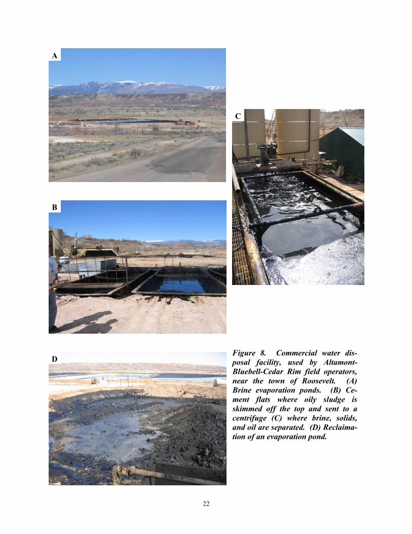
There are four and five commercial disposal facilities in Duchesne and Uintah Counties, respectively (figure 7). Produced brine is disposed of by evaporation in ponds (figure 8A) or injection into saltwater aquifers. For many years Water Disposal Inc. operated three evaporation ponds about 5 miles (8 km) north of the center of the town of Roosevelt (figure 8A). The ponds were installed in 1989 and received brine from operators throughout the Uinta Basin. An abandoned oil well near the disposal facility was converted to an injection well, and brine from the ponds along with newly received brine is injected into the Green River Formation at a depth of about 9800 feet (3300 m). The facility currently receives 2000 to 3000 bbls (300-500 m3) per day of new brine (Chris Denver, Water Disposal Inc., verbal communication, 2004). The disposal facility is using a three-phase centrifuge to recover oil from reclaimed ponds and from brine that it receives and tank bottoms. Fluid, sludge, and contaminated soil from the bottom of the ponds are processed through the centrifuge extracting high-quality oil, brine (which is disposed down the injection well), and a small amount of solids (Chris Denver, Water Disposal Inc., verbal communication, 2004). A truck load of brine typically contains about 2 percent oil. Brine from a truck is pumped into one of three cement flats (figure 8B). The oily sludge is skimmed off the top and sent to the centrifuge where brine, solids, and oil are separated (figure 8C). The brine from the centrifuge and the remaining brine in the flats are sent to storage tanks to be injected down the well. The centrifuge has been a successful technique in reclaiming the evaporation ponds (figure 8D) and extracting high-quality oil from the produced brine and tank bottoms that is lost during the typical disposal process (Chris Denver, Water Disposal Inc., verbal communication, 2004).
20
Figure 7. Location of commercial water disposal facilities used by oil-field operators in the Uinta Basin.
21
Figure 8. Commercial water dis-posal facility, used by Altamont-Bluebell-Cedar Rim field operators, near the town of Roosevelt. (A) Brine evaporation ponds. (B) Ce-ment flats where oily sludge is skimmed off the top and sent to a centrifuge (C) where brine, solids, and oil are separated. (D) Reclaima-tion of an evaporation pond.
A
B
C
D
22
Hydrogen Sulfide
When Pennzoil was the main field operator in the 1990s, they began detecting hydrogen sulfide (H2S) in some of their production tanks (before they sold the operations to Devon). Further study by Devon indicated that the H2S is occurring in wells that produce a minor amount of water. In these wells the water sits in the tanks for an extended period and the H2S is generated by bacterial growth in the tanks and not down hole (John Pully, Devon Energy Corporation, verbal communication, 2004). Low-Volume Gas Wells
There are currently three, shallow, low-volume gas wells producing from the top of the Green River/base of the Uinta Formation. All of the production goes through a gas plant designed to separate associated gas from the oil production. The volume of gas is below what is needed to efficiently run the plant. As a result, producers do not get full value for the gas. Additional shallow gas wells will probably not result in a large enough volume for the gas plant; therefore, it is not economical to drill new shallow gas wells in the area (John Pully, Devon Energy Corporation, verbal communication, 2004). Environmental Issues
Production sites and facilities are well established and there are few environmental issues. Surface test pits were all reclaimed in the 1990s. Fluids from testing and recompletion operations now go into metal pit tanks and then are disposed. Screen cones are placed on the heat treater stacks to prevent birds from getting into the stacks and becoming injured (figure 9). The most significant problem is the expanding population in the area. Homes and cabins are being built in the area and surface owners without mineral rights do not appreciate oil operations on their property (John Pully, Devon Energy Corporation, verbal communication, 2004). Residential expansion near the Roosevelt disposal facility resulted in conflicts between homeowners and the disposal facility because of the occasional smell from the ponds. In a settlement with Roosevelt City, those disposal ponds are being drained and the surfaces reclaimed (Chris Denver, Water Disposal Inc., verbal communication, 2004).
Figure 9. Heat treater with bird screen on the exhaust stack at the El Paso Production Oil and Gas Company Ute Fee 2-33C6, SW1/4SW1/4 section 33, T. 3 S., R. 6 W., UBLM, in Cedar Rim field.
23
TECHNOLOGY TRANSFER
The Utah Geological Survey (UGS) is the Principal Investigator and prime contractor for the PUMPII project. All play maps, reports, databases, and other deliverables produced for the PUMPII project will be published in interactive, menu-driven digital (Web-based and compact disc) and hard-copy formats by the UGS for presentation to the petroleum industry. Syntheses and highlights will be submitted to refereed journals, as appropriate, such as the American Association of Petroleum Geologists (AAPG) Bulletin and Journal of Petroleum Technology, and to trade publications such as the Oil and Gas Journal.
The UGS publication Survey Notes provides non-technical information on contemporary geologic topics, issues, events, and ongoing UGS projects to Utah's geologic community, educators, state and local officials and other decision makers, and the public. Survey Notes is published three times yearly. Single copies are distributed free of charge and reproduction (with recognition of source) is encouraged. The UGS maintains a Web site on the Internet, http://geology.utah.gov. The UGS site includes a page under the heading Utah Geology/Oil, Coal, and Energy, which describes the UGS/DOE cooperative studies (PUMPII, Paradox Basin [two projects], Ferron Sandstone, Bluebell field, Green River Formation), and has a link to the DOE Web site. Each UGS/DOE cooperative study also has its own separate page on the UGS Web site. The PUMPII project page, http://geology.utah.gov/emp/pump/index.htm, contains (1) a project location map, (2) a description of the project, (3) a reference list of all publications that are a direct result of the project, (4) poster presentations, and (5) quarterly technical progress reports.
The technology-transfer plan included the formation of a Technical Advisory Board and a Stake Holders Board. The Technical Advisory Board advises the technical team on the direction of study, reviews technical progress, recommends changes and additions to the study, and provides data. The Technical Advisory Board is composed of field operators from the oil-producing provinces of Utah that may also extend into Wyoming or Colorado. This board ensures direct communication of the study methods and results to the operators. The Stake Holders Board is composed of groups that have a financial interest in the study area including representatives from the State of Utah (School and Institutional Trust Lands Administration and Utah Division of Oil, Gas and Mining) and the Federal Government (Bureau of Land Management and Bureau of Indian Affairs). The members of the Technical Advisory and Stake Holders Boards receive all quarterly technical reports and copies of all publications, and other material resulting from the study. Board members will also provide field and reservoir data, especially data pertaining to best practices. During the quarter, project team members joined Utah Stake Holders Board members in attending the Uinta Basin Oil and Gas Collaborative Group meeting in Vernal, Utah.
An abstract submitted to the AAPG on basin-wide correlation of Green River Formation plays and subplays in the Uinta Basin in Utah has been accepted; the paper will be presented at the poster session titled “New Techniques and Technologies Applied to Rocky Mountain Petroleum Systems” on August 10 during the 2004 AAPG Rocky Mountain Section Meeting in Denver, Colorado. This information will also be released on the UGS project Web page.
24
CONCLUSIONS AND RECOMMENDATIONS A combination of depositional and structural events created the right conditions for oil
generation and trapping in the major oil-producing provinces (Paradox Basin, Uinta Basin, and thrust belt) in Utah and adjacent areas in Colorado and Wyoming. Oil plays are specific geographic areas having petroleum potential due to favorable source rock, migration paths, reservoir characteristics, and other factors. This report focuses on the best completion practices recommended for wells in the Northern Green River Conventional Uinta Basin and Deep Uinta Overpressured plays.
Reservoir analysis indicates that there is a significant amount of oil left to be produced in Altamont-Bluebell-Cedar Rim wells in these plays. Accurately identifying which beds actually contribute to the production and the role that naturally occurring fractures play in the reservoir remains a major problem for maximizing petroleum production. We recommend that operators in the Bluebell field use geophysical and imaging logs as the primary tools for selecting perforations in new wells, not drilling shows as is commonly done. This should result in a reduction of the number of beds perforated, and more effective treatment. In recompletion of existing wells, cased-hole logs can help identify additional beds to be perforated, and if necessary, identify beds that can be treated individually.
The treatment methods used by operators in the Altamont-Bluebell-Cedar Rim field trend have not changed significantly over the years, except for treating larger intervals and more perforations. Almost all the completions follow the same general procedures, varying only slightly in the volume of acid and the types of additives used. As a result, no treatment method appears better than another, because there is such little difference between them.
As treatment intervals get larger, it is apparent that many of the beds are not getting treated because of the difficulty of diverting the acid into so many different beds. Staging acid treatments over smaller (500-foot [150 m]) intervals and greatly increasing the amount of diversion material used has been shown by operators in Bluebell field to be effective treatment techniques. Particularly in newer wells, perforating fewer beds and treating shorter gross intervals can result in more effective completions. In recompleting wells, staging the treatments over shorter intervals and more effective diversion of the treatment fluid to the desired interval, will result in better completions. Typically, an operator treating a 1500-foot (500-m) interval will treat the lower 500 feet (160 m), move the packer up and treat the middle 500 feet (152 m), and then treat the upper 500-foot (160-m) interval. Ideally, the diversion material plugs the perforations of a stage before moving up hole so only 500-foot (160-m) sections are being treated at a time.
Older wells that have been recompleted many times eventually become uneconomical to retreat. In these wells only a minor incremental increase in the oil production rate occurs after treatment because so much of the acid is going into beds that are depleted of oil. A bed-scale completion technique could be effective in older wells nearing depletion where a larger staged completion is no longer economical. Therefore, in older wells it is recommended that treatment of a few individual beds be attempted using a dual packer tool. This way, only the few beds with remaining oil potential are acidized, reducing the size of the treatment needed, and providing more effective stimulation of the beds with remaining potential.
Regardless of what type of stimulation is tried, who tries it, or what it costs, better bed evaluation is critical to increasing production from the Altamont-Bluebell-Cedar Rim field trend. The interval to be treated could be reduced by (1) isolation with a bridge plug and
25
packer, (2) use of a Pin Point Injection packer (PPI tool), or (3) use of a packer and the natural pressure gradient which is present within the formation. Large perforated intervals are extremely difficult to treat down 2-7/8-inch-diameter (7-cm) tubing. Good diversion is critical to treating the entire interval and a high enough pumping rate must be maintained to effectively carry the diverting agent.
HCl has been, and still is, the recommended treating fluid. The following list of additives would be advisable to be run per 1000 gallons (3800 L) of 15 percent HCl:
1. 5 to 10 gallons (19-38 L) corrosion inhibitor (temperature dependent), 2. 3 to 10 gallons (11-38 L) surfactant (concentration will vary depending on
compatibility of surfactant with the produced oil), 3. 3 to 7 gallons (11-26 L) clay control (concentration will vary depending type of
clay control additive that is used), 4. 10 gallons (28 L) iron control (minimum), 5. 10 gallons (28 L) acid gelling agent, 6. 10 gallons (28 L) solvent (minimum), and 7. 10 gallons (28 L) scale inhibitor.
In addition to the additives, the tubing should be pickled and reversed out just prior to
doing the main acid treatment. This may involve more cost, but will minimize formation damage from iron dissolved from the tubulars. A rule of thumb for pickling tubulars is to use 100 gallons (375 L) of HCl for every 1000 feet (300 m) of tubing. The treating fluid should be recovered as quickly as possible, not allowing it to sit in the formation; this will help prevent fines and other solids from dropping out in the formation. The initial acid treatment is generally the largest and appears to be the most effective. If additional acid treatments are pumped, it is advisable to pump volumes similar to, or smaller than, the initial acid treatment. The most cost-effective acid treatment appears to be between 20,000 and 30,000 gallons (75,700 and 113,600 L) of 15 percent HCl pumped in four acid stages. This would mean pumping three diverter stages with enough volume to divert the fluid from one zone to another. The diverter fluid should be gelled so that the friction characteristics are similar to that of the acid. The diverter fluid should also be compatible with the diverter material, and contain the same surfactants and clay control additives that are used in the acid system. If ball sealers are used, a minimum of 50 percent excess will give proper diversion if the fluid volume and pumping rate are appropriate, and the perforations are in good shape.
Operators generally believe that past performance shows that proppant fracture treatments don't work in the Altamont-Bluebell-Cedar Rim field trend. However, with over 300 wells drilled in the Bluebell field alone, only 2 percent of the treatments were proppant fracture treatments, indicating that hydraulic fracturing with proppant has not been adequately tested, mainly because of the cost. Treatments that were hydraulically fractured with a proppant used only a small volume of sand as the propping agent. The ability to do high-rate proppant fracs over large intervals has been proven in other fields in the Uinta Basin and should be possible in the Altamont-Bluebell-Cedar Rim field trend. Many older wells may not be suitable for this treatment, but newer wells should be considered as likely candidates for high-rate, proppant-fracture treatments.
Variations in six parameters affect the precipitation of CaCO3 scale from produced oil-well waters in the Altamont-Bluebell-Cedar Rim field trend: (1) basic water chemistry, (2) pH,
26
(3) CO2 content, (4) pressure changes, (5) salinity changes, and (6) temperature changes. Waters with high percentages of both calcium and bicarbonate favor greater precipitation. Low-pH (more acidic) waters precipitate less CaCO3 than high-pH (more basic) waters. High CO2 content favors less precipitation than low CO2 content. Decreases in pressure and/or increased turbulence favor the precipitation of CaCO3. Reductions in salinity favor less precipitation. Increased temperatures, both initial and equilibrium, favor increased CaCO3 precipitation. The co-production of Green River and Wasatch Formation waters increases the amount of CaCO3 scale that is produced over that which is produced from Wasatch water alone.
There is no clear correlation between hydrocarbon production and type and size of treatment. However, the acid treatments are apparently understimulating the wells, as shown by the limited amount of time the wells are in linear flow. Surprisingly, no correlation occurs between the amount of acid pumped and the size of the interval being treated. Moderate-sized acid treatments are about as economical as large acid treatments regardless of the interval being treated. Most wells in the area have been treated more than once. Typically the first and second treatments yield the best results, whereas the third and fourth treatments do not appear to be as effective, but these later treatments were also typically smaller. The first and second treatments appear to be fairly effective in increasing production for up to four to five months. Later treatments are probably less effective because they are applied to older wells that are partially depleted. The volume of the treatment does not appear to be a major factor. Treatments that range from 20,000 to 30,000 gallons (75,700-113,600 L) seem to be slightly more effective, but apparently the most critical acid treatment, is the first one. If additional acid treatments are to be pumped, they should be about the same size as the first treatment, not smaller as is often the case.
Higher pumping rates and well-head-treating pressure result in more effective treatments. The higher pressures and pumping rates could be indications of good diversion taking place, which allows more of the treatment fluids to enter more of the formation. However, higher pumping rates that just increase the WHTP are not necessary. A pumping rate between 8 and 12 BPM (1.12-1.68 MTM), with proper gelling agents in the fluid, will divert the fluid to the perforated intervals and maintain a reasonable WHTP. By holding a constant pumping rate and allowing the diverter to do its job, the WHTP should increase and break back as the diverter works. Maximum pressure should be reached toward the end of the treatment if enough diverter is pumped properly.
At ultra-high pumping rates, treating an 800- to 1000-foot (240-300 m) interval is realistic. One way to obtain ultra-high pumping rates in new wells is to pull the tubing out of the hole and pump down the casing. By pumping down the casing, WHTP pressure would be approximately 5000 psi (34,500 kPa) at pumping rates up to 100 BPM (16 m3/min). Ultra-high pumping rates may not be an option in older wells due to bad casing, inadequate cement, or a combination of both. Increasing pumping rates down 2-7/8-inch-diameter (7-cm) tubing will only increase the WHTP, not the BHTP. Changing out the 2-7/8- to 3-1/2-inch-diameter (7-9-cm) tubing to increase pumping rates may not be cost effective. There will be a rate increase with the larger diameter pipe, but friction is still a significant problem. When treating down the tubing, an adequate pumping rate must be maintained and the pressure allowed to increase on its own due to the diversion and sealing of perforations. Successful treatment requires that enough diverter and sufficient fluid is pumped to treat all of the perforated beds in the interval.
High-rate, hydraulic-fracture treatments are a viable option; this overlooked completion technique should be considered for newer wells. Extended hydro-jetting has not been used but
27
may be a technique to overcome near-wellbore damage caused by drilling and treatment fluids. Extended hydro-jetting can also be used to provide a small horizontal wellbore into several producing intervals within the same well.
The TDT and anisotropy logs appear to be reliable tools for evaluating remaining hydrocarbon potential and fracture density in a cased-hole well that has been producing oil for many years. This type of data can be used to identify potentially productive beds that are not perforated in older wells, eliminate the acidizing of previously perforated beds that have little to no potential, and determine if the acid fracture treatment is hydraulically fracturing the formation.
Based on the UGS/DOE-funded Bluebell field demonstration project (Morgan and Deo, 1999; Morgan, 2003), we further recommend the following:
1. Use a dual packer tool instead of a retrievable packer and bridge plug so several
beds can be treated in one day to greatly reduce the completion cost. 2. Set the packers between perforated intervals that are at least 50 feet (15 m) apart to
reduce the risk of communication behind the casing. 3. Use the anisotropy and TDT logs to select beds that are fractured and have relatively
low water saturation. 4. Use a treating pressure high enough to fracture the formation, especially if the
anisotropy log indicates that some of the beds being treated do not have open fractures.
Produced high-paraffin oil is stored on location in insulated tanks and the production
facilities have a heat treater that keeps the oil above the pour point temperature. Screen cones are placed on the heat treater stacks to prevent birds from getting into the stacks. Three types of pumps are commonly used in field trend: (1) the standard pump jack, both center and rear gearbox, (2) the submersible pump, and (3) the rotary-flex pump. Water production is a significant part of the operating costs, but a water gathering system with water-injection wells enables disposal of 90 percent of the produced water at a significant cost savings. Fluids from testing and recompletion operations now go into metal pit tanks prior to disposal.
Although production is in decline in the Altamont-Bluebell-Cedar Rim field trend, numerous wells have many productive beds that have not been fully exploited. As a result, production should continue from the area for many decades if these beds can be identified and effectively drained. Enhanced oil recovery (EOR) has not been attempted in the field trend because the extensive fracturing in the reservoir would make EOR very unpredictable and could result in early breakthrough of any injected fluids or gases (John Pully, Devon Energy Corporation, verbal communication, 2004).
ACKNOWLEDGMENTS
Funding for this ongoing research was provided as part of the DOE Preferred Upstream Management Program (PUMP II) of the U.S. Department of Energy, National Petroleum
28
Technology Office, Tulsa, Oklahoma, contract number DE-FC26-02NT15133. The Contracting Officer's Representative is Rhonda Jacobs.
John Pully, Senior Operations Engineer, Devon Energy Corporation, Neola, Utah, and Chris Denver, Water Disposal Inc., Roosevelt, Utah, provided excellent information on best practices used in the greater Altamont-Bluebell-Cedar Rim field trend.
Jim Parker and Vicky Clarke of the UGS prepared the figures. This report was reviewed by Dave Tabet and Mike Hylland of the UGS. Cheryl Gustin, UGS, formatted the manuscript.
REFERENCES Allison, M.L., and Morgan, C.D., 1996, Increased oil production and reserves from improved
completion techniques in the Bluebell field, Uinta Basin, Utah - annual report for the period October 1, 1994 to September 30, 1995: U.S. Department of Energy, DOE/BC/14953-14, 118 p.
Deo, M.D., and Morgan, C.D., 1998, Increased oil production and reserves from improved
completion techniques in the Bluebell field, Uinta Basin, Utah - annual report for the period October 1, 1996 to September 30, 1997: U.S. Department of Energy, DOE/BC/14953-20, 66 p.
Dubiel, R.F., 2003, Geology, depositional models, and oil and gas assessment of the Green
River total petroleum system, Uinta-Piceance province, eastern Utah and western Colorado, in U.S. Geological Survey Uinta-Piceance Assessment Team, compilers, Petroleum systems and geologic assessment of oil and gas in the Uinta-Piceance province, Utah and Colorado: U.S. Geological Survey Digital Data Series DDS-69-B.
Energy Information Administration, 2001, U.S. crude oil, natural gas, and natural gas liquids
reserves – 2000 annual report: U.S. Department of Energy DOE/EIA-0216 (2000), p. 20.
Fouch, T.D., 1975, Lithofacies and related hydrocarbon accumulations in Tertiary strata of the
western and central Uinta Basin, Utah, in Bolyard, D.W., editor, Deep drilling frontiers in the central Rocky Mountains: Rocky Mountain Association of Geologists Symposium, p. 163-173.
1992, Oil and gas in uppermost Cretaceous and Tertiary rock, Uinta Basin, Utah, in Fouch, T.D., Nuccio, V.F., and Chidsey, T.C., Jr., editors, Hydrocarbon and mineral resources of the Uinta Basin, Utah and Colorado: Utah Geological Association Publication 20, p. 9-47.
Hintze, L.F., 1993, Geologic history of Utah: Brigham Young University Studies Special
Publication 7, 202 p.
29
Lucas, P.T., and Drexler, J.M., 1976, Altamont-Bluebell – a major naturally fractured stratigraphic trap, in North American gas fields: American Association of Petroleum Geologists Memoir 24, p. 121-135.
Morgan, C.D., 1997, Increased oil production and reserves from improved completion
techniques in the Bluebell field, Uinta Basin, Utah - annual report for the period October 1, 1995 to September 30, 1996: U.S. Department of Energy, DOE/BC/14953-19, 34 p.
---(editor), 2003, The Bluebell oil field, Uinta Basin, Duchesne and Uintah Counties, Utah -
characterization and oil well demonstration: Utah Geological Survey Special Study 106, 96 p.
Morgan, C.D., and Deo, M.D., 1999, Increased oil production and reserves from improved
completion techniques in the Bluebell field, Uinta Basin, Utah - annual report for the period October 1, 1997 to September 30, 1998: U.S. Department of Energy, DOE/BC/14953-21, 46 p.
Narr, W., and Currie, J.B., 1982, Origin of fracture porosity—example from Altamont field,
Utah: American Association of Petroleum Geologists Bulletin, v. 66, no. 9, p. 1231-1247.
Nuccio, V.F., Schmoker, J.W., and Fouch, T.D., 1992, Thermal maturity, porosity, and
lithofacies relationships applied to gas generation and production in Cretaceous and Tertiary low-permeability (tight) sandstones, Uinta Basin, Utah, in Fouch, T.D., Nuccio, V.F., and Chidsey, T.C., Jr., editors, Hydrocarbon and mineral resources of the Uinta Basin, Utah and Colorado: Utah Geological Association Publication 20, p. 77-93.
Pitman, J.K., Fouch, T.D., and Goldhaber, M.B., 1982, Depositional setting and diagenetic
evolution of some Tertiary unconventional reservoir rocks, Uinta Basin, Utah: American Association of Petroleum Geologists Bulletin, v. 66, no. 10, p. 1581-1596.
Reid, M., Holcomb, D., and Waak, K.A., 1995, Using low density tracers to evaluate acid
treatment diversion: Society of Petroleum Engineers Proceedings of the Joint Rocky Mountain Section/Low Permeability Reservoir Symposium, SPE 29595, p. 405-414.
Ryder, R.T., Fouch, T.D., and Elison, J.H., 1976, Early Tertiary sedimentation in the western
Uinta Basin, Utah: Geological Society of America Bulletin, v. 87, no. 4, p. 496-512. Smouse, DeForrest, 1993, Altamont-Bluebell, in Hill, B.G., and Bereskin, S.R., editors, Oil and
gas fields of Utah: Utah Geological Association Publication 22, non-paginated. Stearns, D.W., and Friedman, M., 1972, Reservoirs in fractured rocks, in King, R.E., editor,
Stratigraphic oil and gas fields—classification, exploration methods, and case histories: American Association of Petroleum Geologists Memoir 16, p. 82-106.
30
Utah Division of Oil, Gas and Mining, 2002, Oil and gas production report, December 2002: non-paginated.
---2003, Oil and gas production report, November 2003: non-paginated.