15
THE INFLUENCES UTP CABLING INSTALLATION TECHNIQUES TO RATE TRANSFER IRBA FAIRUZ THUFAILAH SMA 2 KUDUS
5/12/2018 Makalah_Komputer_SMAN 2 Kudus_Irba Fairuz Thufailah - slidepdf.com
http://slidepdf.com/reader/full/makalahkomputersman-2-kudusirba-fairuz-thufailah 1/15
THE INFLUENCES UTP CABLING INSTALLATION
TECHNIQUES TO RATE TRANSFER
IRBA FAIRUZ THUFAILAH
SMA 2 KUDUS

5/12/2018 Makalah_Komputer_SMAN 2 Kudus_Irba Fairuz Thufailah - slidepdf.com
http://slidepdf.com/reader/full/makalahkomputersman-2-kudusirba-fairuz-thufailah 2/15
1
1. INTRODUCTION
1.1 BACKGROUND
The term of internet is actually an acronym standfor interconnected networks computers means
computer network which are connected each other (Supriyanto, 2009). The internet is a network of computers that could be categorized as a WAN, connecting millions of computer surround the
world, without borders, in which every person who has a computer can join the network by simply
connection to the internet service provider (internet service provider / ISP).
To connect the PC to the internet requires network devices such as Network Interface
Card (NIC), Router, Bridge, Switch, Hub, Repeater, and Server. And a connector cable between
devices are needed. There are several types of cables one, is cable or UTP Unshielded Twisted
Pair. UTP cable is a form of a two-conductor cable bundled with the aim to reduce or eliminateelectromagnetic interference. This cable has two kinds of wiring that is Crossover Type
and Straight Type. And each cable has its own color rule sequence for each pin in the connector.
Researchers therefore initiated to reduce the kinds of neighbor combination of UTP cabling.
1.2 PROBLEM STATEMENT
1. How to use another combination of UTP cable?
2. How about the relationship between the combination of another UTP cable with the transfer
rate?
1.3 PURPOSE
1. To get a new combination of the various of UTP cabling installation
2. To know which combination has more advantages in transferring data
5/12/2018 Makalah_Komputer_SMAN 2 Kudus_Irba Fairuz Thufailah - slidepdf.com
http://slidepdf.com/reader/full/makalahkomputersman-2-kudusirba-fairuz-thufailah 3/15
2
1.4 TH EORETICAL FUNDAMENTAL
1.4.1 UTP CABLE
There are two kinds of TP cable:
1. For cable telephone cable that contains 4 pieces (STP)
2. For computer network cable containing 8 pieces (UTP)
UTP (Unshielded Twisted Pair) serves as a medium for networking with impedance of
100 ohms (Enterprise, 2008). Called unshielded because less resistant to electromagnetic
interference. It is called twisted pair because in it there pair cables are arranged or mutually
spiral.
Cable UTP or Unshielded Twisted Pair Cable or Ethernet or usually called the LAN
cable is a cable used to connect inter-related equipment computer network (computers, hub,
switch, router). The meaning of the UTP cable is only the cord, while the head of the cord is
8 position modular connectors (8P8C) is commonly called an RJ-45 (RJ = register jack).
Cable Unshielded Twisted Pair (UTP) consists of four pairs of strings medium. Each pair is
separated by protective layer. This type of cable is solely rely on conselations effects produced
by pairs of strings, for to limit signal degradation caused by Electromagnetic Interference
(EMI) and Radio Frequency Interference (RFI). The colors of UTP cable consistof white green, green, white orange, blue, orange, white brown, brown.
1.4.2 CONNECTOR
Connector otherwise is known as the Registered Jack. Connectors used for computer
networks is an RJ-45. RJ-45 connector is eight pin connector that are used to connect the UTP
cable with socket NIC/Ethernet. From eight pin, there are only four pin that has a function. That
is pin number 1, 2, 3 and 6. Pin number 1 serves to transmit +, pin number 2 serves to transmit -
, pin number 3 serves to receives +, and pin number 6 receives-. Four pins other unused.
5/12/2018 Makalah_Komputer_SMAN 2 Kudus_Irba Fairuz Thufailah - slidepdf.com
http://slidepdf.com/reader/full/makalahkomputersman-2-kudusirba-fairuz-thufailah 4/15
3
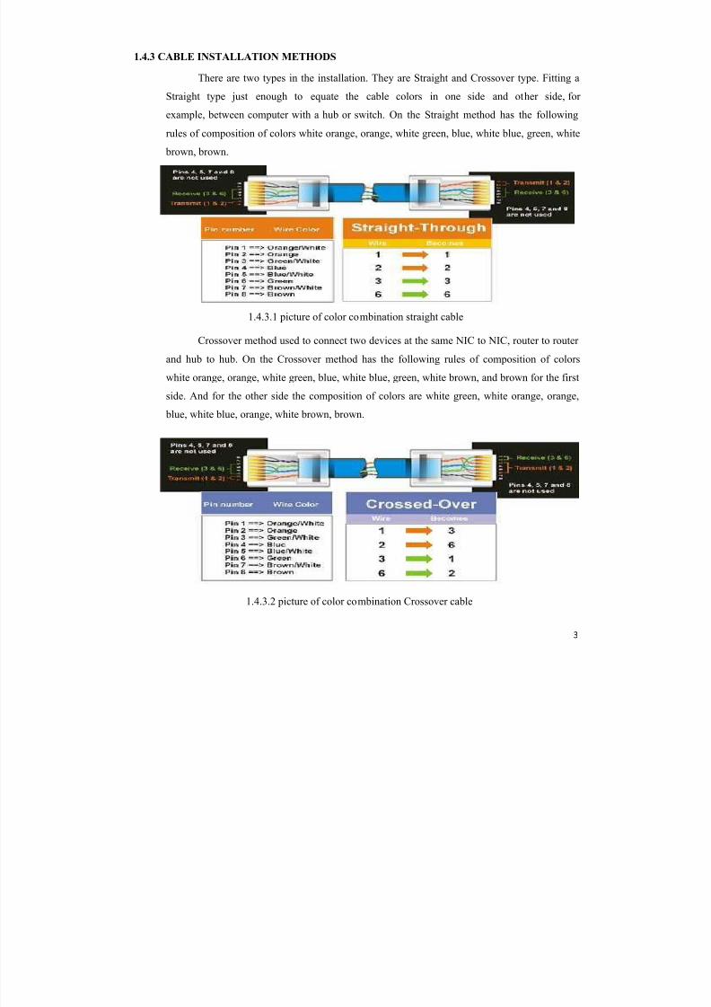
1.4.3 CABLE INSTALLATION METHODS
There are two types in the installation. They are Straight and Crossover type. Fitting a
Straight type just enough to equate the cable colors in one side and other side, for
example, between computer with a hub or switch. On the Straight method has the following
rules of composition of colors white orange, orange, white green, blue, white blue, green, white brown, brown.
Crossover method used to connect two devices at the same NIC to NIC, router to router
and hub to hub. On the Crossover method has the following rules of composition of colors
white orange, orange, white green, blue, white blue, green, white brown, and brown for the first
side. And for the other side the composition of colors are white green, white orange, orange,
blue, white blue, orange, white brown, brown.
1.4.3.1 picture of color combination straight cable
1.4.3.2 picture of color combination Crossover cable

5/12/2018 Makalah_Komputer_SMAN 2 Kudus_Irba Fairuz Thufailah - slidepdf.com
http://slidepdf.com/reader/full/makalahkomputersman-2-kudusirba-fairuz-thufailah 5/15
4
1.4.4 TRANSFER RATE
Data transfer rate is the number of bits of data that passes through one medium in one
second. Generally written in bits per second (bits per second) and symbolized bit/s or bps.
Data transfer rate refers to the achieved average net bit rate that is delivered to the
application layer, exclusive of all protocol overhead, data packets retransmissions, etc. For
example, in the case of file transfer, the data transfer rate corresponds to the achieved file
transfer rate. The file transfer rate in bit/s can be calculated as the file size (in bytes), divided by
the file transfer time (in seconds), and multiplied by eight.
As an example, the data transfer rate of a V.92 voiceband modem is affected by the modem
physical layer and data link layer protocols. It is sometimes higher than the physical layer data
rate due to V.44 data compression, and sometimes lower due to bit-errors and automatic repeat
request retransmissions.
2. RESEARCH METODOLOGY
2.1 TOOLS AND MATERIALS
1.
Cable UTP
2. Connector RJ-45
3. Modem
4. Crimping tools
5. Personal computer (PC) /notebook
2.2 HOW TO MAKE A VARIOUS CABLE
1. First, prepare all equipment, especially cables, RJ-45 connectors and crimping tool.
2. Second, cut the cable of the desired and peel the first layer of cable.
5/12/2018 Makalah_Komputer_SMAN 2 Kudus_Irba Fairuz Thufailah - slidepdf.com
http://slidepdf.com/reader/full/makalahkomputersman-2-kudusirba-fairuz-thufailah 6/15
5
3. Third, arrange the cable color and tidy up the end of cable.
4. Then, Plug the cable into the connector and make sure the end of cable right at pin
connector RJ-45.
5.
Last, make sure the position of cable in the connector and plug in the connector and cableinto crimpt tool. Firmly press until the cable is connected to the connector.
2.3 HOW TO TEST THE TRANSFER RATE
1. Connecting the modem to the computer using a cable that has been made
2. Windows + R, then type ping www.google.com ±t
2.4 HOW TO CALCULATING THE RATE TRANSFER OF UTP CABLING
To calculate the transfer rate of cable is used the formula :
Formula =
data capacity
Second
5/12/2018 Makalah_Komputer_SMAN 2 Kudus_Irba Fairuz Thufailah - slidepdf.com
http://slidepdf.com/reader/full/makalahkomputersman-2-kudusirba-fairuz-thufailah 7/15
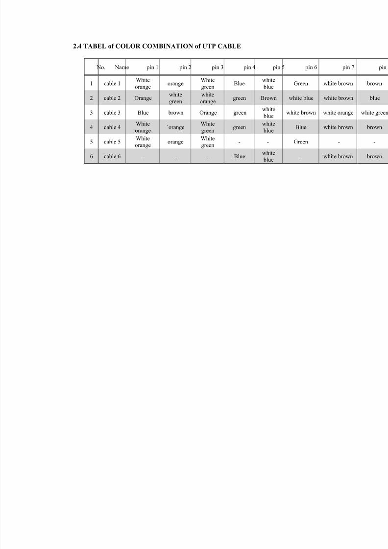
2.4 TABEL of COLOR COMBINATION of UTP CABLE
No. Name pin 1 pin 2 pin 3 pin 4 pin 5 pin 6
1 cable 1White
orangeorange
White
greenBlue
white
blueGreen
2 cable 2 Orangewhite
green
white
orangegreen Brown white blue
3 cable 3 Blue brown Orange greenwhite
bluewhite brown
4 cable 4White
orange`orange
White
greengreen
white
blueBlue
5 cable 5White
orange
orangeWhite
green
- - Green
6 cable 6 - - - Bluewhite
blue-
5/12/2018 Makalah_Komputer_SMAN 2 Kudus_Irba Fairuz Thufailah - slidepdf.com
http://slidepdf.com/reader/full/makalahkomputersman-2-kudusirba-fairuz-thufailah 8/15
7
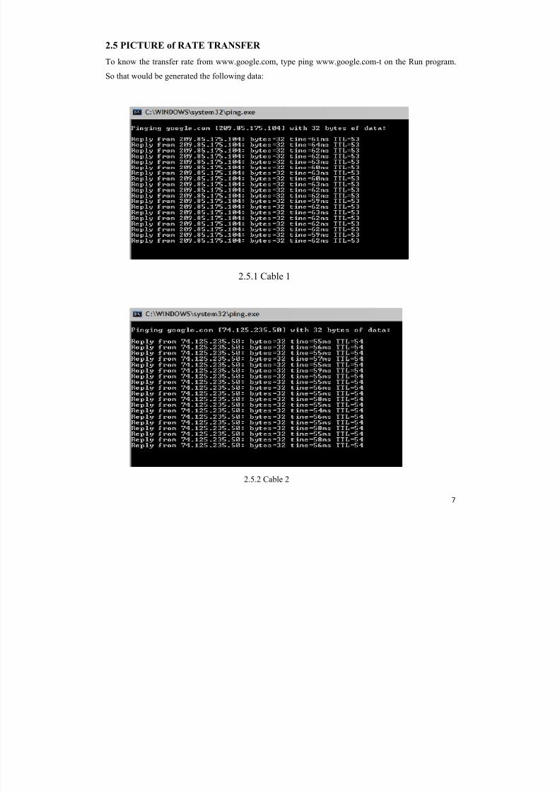
2.5 PICTURE of RATE TRANSFER
To know the transfer rate from www.google.com, type ping www.google.com-t on the Run program.
So that would be generated the following data:
2.5.1 Cable 1
2.5.2 Cable 2
5/12/2018 Makalah_Komputer_SMAN 2 Kudus_Irba Fairuz Thufailah - slidepdf.com
http://slidepdf.com/reader/full/makalahkomputersman-2-kudusirba-fairuz-thufailah 9/15
8
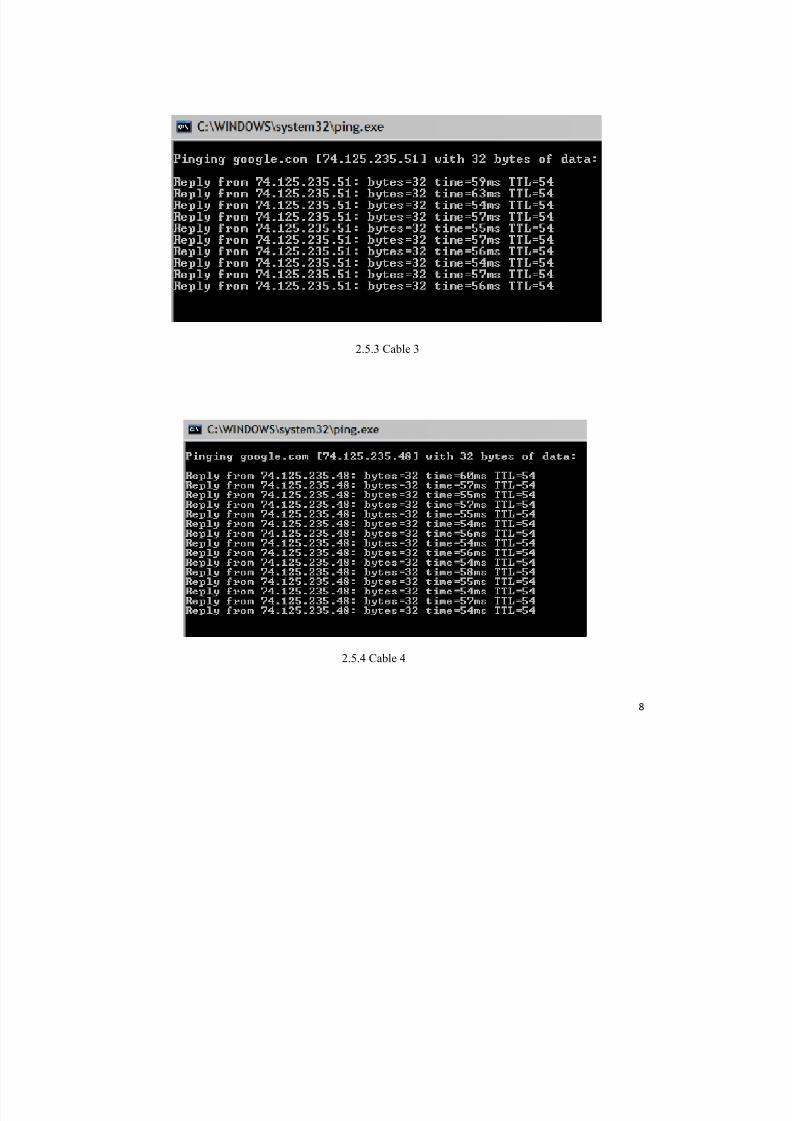
2.5.3 Cable 3
2.5.4 Cable 4
5/12/2018 Makalah_Komputer_SMAN 2 Kudus_Irba Fairuz Thufailah - slidepdf.com
http://slidepdf.com/reader/full/makalahkomputersman-2-kudusirba-fairuz-thufailah 10/15
9
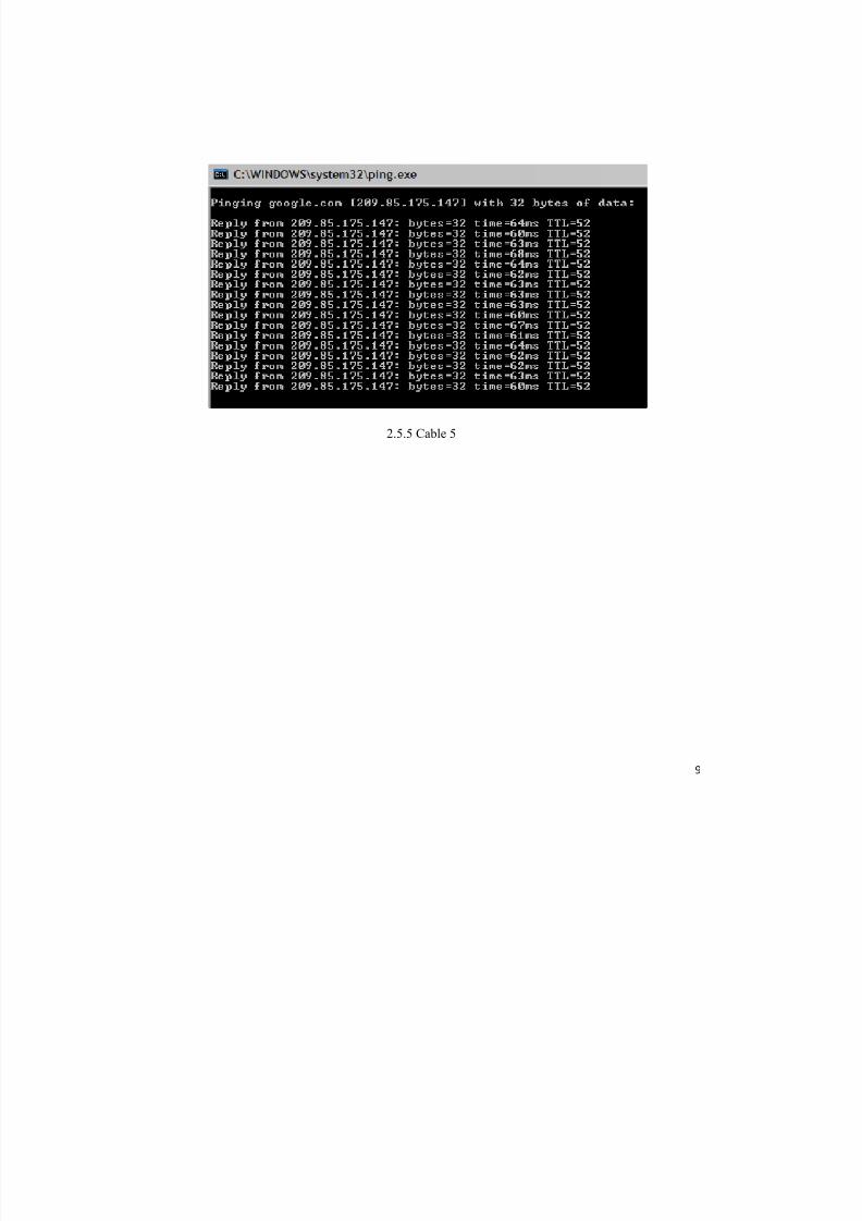
2.5.5 Cable 5

5/12/2018 Makalah_Komputer_SMAN 2 Kudus_Irba Fairuz Thufailah - slidepdf.com
http://slidepdf.com/reader/full/makalahkomputersman-2-kudusirba-fairuz-thufailah 11/15
10
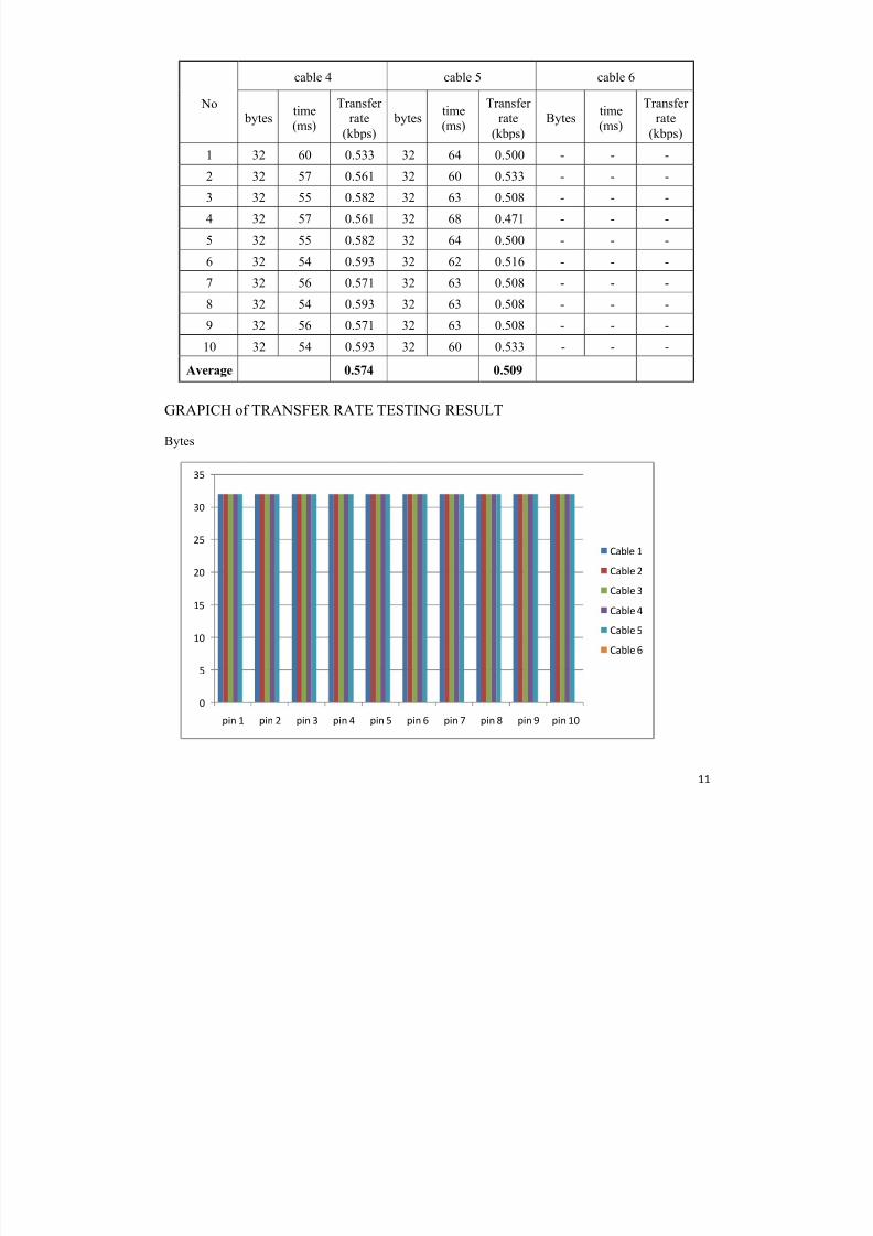
2.6 TABEL of TRANSFER RATE TESTING RESULT
From the results of ping www.google.com-t, obtained data about the capacity of data (bytes)
and time (ms), so it can be determined the amount of Transfer Rate.
No.
cable 1 cable 2 cable 3
bytestime
(ms)
Transfer
rate(kbps)
Bytestime
(ms)
Transfer
rate(kbps)
Bytestime
(ms)
Transfer
rate(kbps)
1 32 61 0.525 32 55 0.582 32 59 0.542
2 32 64 0.500 32 56 0.571 32 63 0.508
3 32 62 0.516 32 55 0.582 32 54 0.593
4 32 62 0.516 32 57 0.561 32 57 0.561
5 32 63 0.508 32 55 0.582 32 55 0.582
6 32 60 0.533 32 59 0.542 32 57 0.561
7 32 63 0.508 32 55 0.582 32 56 0.571
8 32 60 0.533 32 55 0.582 32 54 0.593
9 32 63 0.508 32 56 0.571 32 57 0.561
10 32 62 0.516 32 55 0.582 32 56 0.571
Average 0.516 0.574 0.564
5/12/2018 Makalah_Komputer_SMAN 2 Kudus_Irba Fairuz Thufailah - slidepdf.com
http://slidepdf.com/reader/full/makalahkomputersman-2-kudusirba-fairuz-thufailah 12/15
11
No
cable 4 cable 5 cable 6
bytestime(ms)
Transfer rate
(kbps)
bytestime(ms)
Transfer rate
(kbps)
Bytestime(ms)
Transfer rate
(kbps)
1 32 60 0.533 32 64 0.500 - - -
2 32 57 0.561 32 60 0.533 - - -
3 32 55 0.582 32 63 0.508 - - -
4 32 57 0.561 32 68 0.471 - - -
5 32 55 0.582 32 64 0.500 - - -
6 32 54 0.593 32 62 0.516 - - -
7 32 56 0.571 32 63 0.508 - - -
8 32 54 0.593 32 63 0.508 - - -
9 32 56 0.571 32 63 0.508 - - -
10 32 54 0.593 32 60 0.533 - - -
Average 0.574 0.509
GRAPICH of TRANSFER RATE TESTING RESULT
Bytes
0
5
10
15
20
25
30
35
pin 1 pin 2 pin 3 pin 4 pin 5 pin 6 pin 7 pin 8 pin 9 pin 10
Cable 1
Cable 2
Cable 3
Cable 4
Cable 5
Cable 6
5/12/2018 Makalah_Komputer_SMAN 2 Kudus_Irba Fairuz Thufailah - slidepdf.com
http://slidepdf.com/reader/full/makalahkomputersman-2-kudusirba-fairuz-thufailah 13/15
12
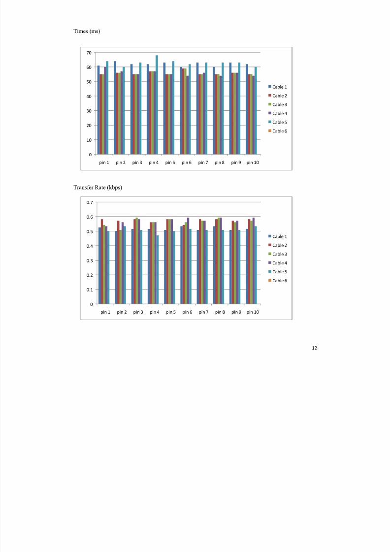
Times (ms)
Transfer Rate (kbps)
0
10
20
30
40
50
60
70
pin 1 pin 2 pin 3 pin 4 pin 5 pin 6 pin 7 pin 8 pin 9 pin 10
Cable 1
Cable 2
Cable 3
Cable 4
Cable 5
Cable 6
0
0.1
0.2
0.3
0.4
0.5
0.6
0.7
pin 1 pin 2 pin 3 pin 4 pin 5 pin 6 pin 7 pin 8 pin 9 pin 10
Cable 1
Cable 2
Cable 3
Cable 4
Cable 5
Cable 6
5/12/2018 Makalah_Komputer_SMAN 2 Kudus_Irba Fairuz Thufailah - slidepdf.com
http://slidepdf.com/reader/full/makalahkomputersman-2-kudusirba-fairuz-thufailah 14/15
13
From the data above, it is known that the cable 1 has an average of transfer rate 0.516 Kbps,
cable 2 has an average of transfer rate 0.574 Kbps, cable 3 has an average of transfer rate 0.564 Kbps,
cable 4 has an average of transfer rate 0.574 Kbps, and cable 5 has an average of transfer rate 0.509
Kbps. For cables 6 cannot connect, because the pins are used only pins number 4, 5, 7, 8 which are in
the theory of the pin, it is not used.
5/12/2018 Makalah_Komputer_SMAN 2 Kudus_Irba Fairuz Thufailah - slidepdf.com
http://slidepdf.com/reader/full/makalahkomputersman-2-kudusirba-fairuz-thufailah 15/15
14
3. RESULT
a. From the research above it is known that UTP cabling techniques on RJ-45 connector that do
not follow the standard from Microsoft was no problem on internet transfer. Because the data
transfer occurs only in pin numbers 1, 2, 3 and 6. So if the cable color change do not give a
specific impact.
b. From the research above it can be seen that no effect on the transfer rate internet. The rate of
which use 8 pin cables compared with using only 4 pins has the same result.
4. CONCLUSION
UTP cabling or LAN cable has a standard rules set by Microsoft. And the rule requires us to
memorize the color sequence. And based on the research above, proving that the composition rules are
not give an effect. And the color composition does not affect the transfer speed of the internet.
5. REFERENCES
Supriyanto. (2009). TIK SMP Kelas IX. Yudhistira.
Enterprise, J. (2008). Membuat Jaringan Komputer Tanpa Bantuan Tekhnisi. Jakarta: PT Elex Media
Komputindo.


