12
Up to a year of clean living. MAKE: PROJECTS Mad Monster Candy Snatch Game Put the fun in “fun-sized” candy! By Bob Knetzger 80 74 39 1

Up to a year of clean living.
MAKE: PROJECTS
Mad Monster Candy Snatch GamePut the fun in “fun-sized” candy!
By Bob Knetzger
80 74 39 1

This article �rstappeared in Make:Volume 41.
Here’s a classic toy reimagined for you to make just in time forHalloween candy-giving and party fun. It’s the Mad Monster CandySnatch game, which combines the nerve-wracking dexterity of theold classic Operation game (BZZZZZT!) with a fun monster head–shaped candy dispenser. Make those little goblins earn their treatswith this tricky game!
It’s simple to make and you can customize the play to be as easy ordif�cult as you like. You can even personalize it with your own voice,choice sayings, and sound effects.
80
74
39
1

The see-through green monster head is �lled with fun-sized candies.Do you dare to snatch a snack? Use the forceps to carefully reach inside its mouth. If youcan maneuver out a candy, you’ve won a treat! But be careful — if you touch the side youlose! The monster wakes up with crackling, shocking sound effects and announces “YOUMAKE MONSTER MAD! YOU LOSE!” as his angry eyes �ash red. No treat for you!
00:00 00:12

PARTSSoda bottle, large, green-colored Iused a ginger ale bottle
Doorstop spring Get the kind thathas a tapering large-to-smallconical shape for just the rightamount of bendiness.
Aluminum tape not silver-coloredduct tape — real metal tape!
Alligator clip jumper wires (6)
Tweezers, long
Knife switch, DPDT
RadioShack #275-1537
Sound recording moduleRadioShack #276-1323
Wire
LEDs, super bright, red (2)
Power transistor, TIP31 NPN
Resistor, 220Ω
9-volt battery clip with leads
Perf board, small piece
Foam mounting tape, double-sided
Wood board, about 6"×10"×1" thickfor the base. Anything will work:particleboard, plywood, or solidwood
STEPSPROJECT STEPS1. Make the Monster’s head
2. Make the base
3. Hack the sound module
4. Make the circuit
5. Mount components to board
6. Assemble the game
Paint, black and yellow
Screws from your hardware jar
Masking tape
Label sheet, adhesive-backed,blank
Cutting template
Face label template
Halloween candies “fun size” minicandy bars or any small wrappedcandy you can pick up withtweezers
ADVERTISEMENT
Step #1: Make the Monster’s head
7. How to Play
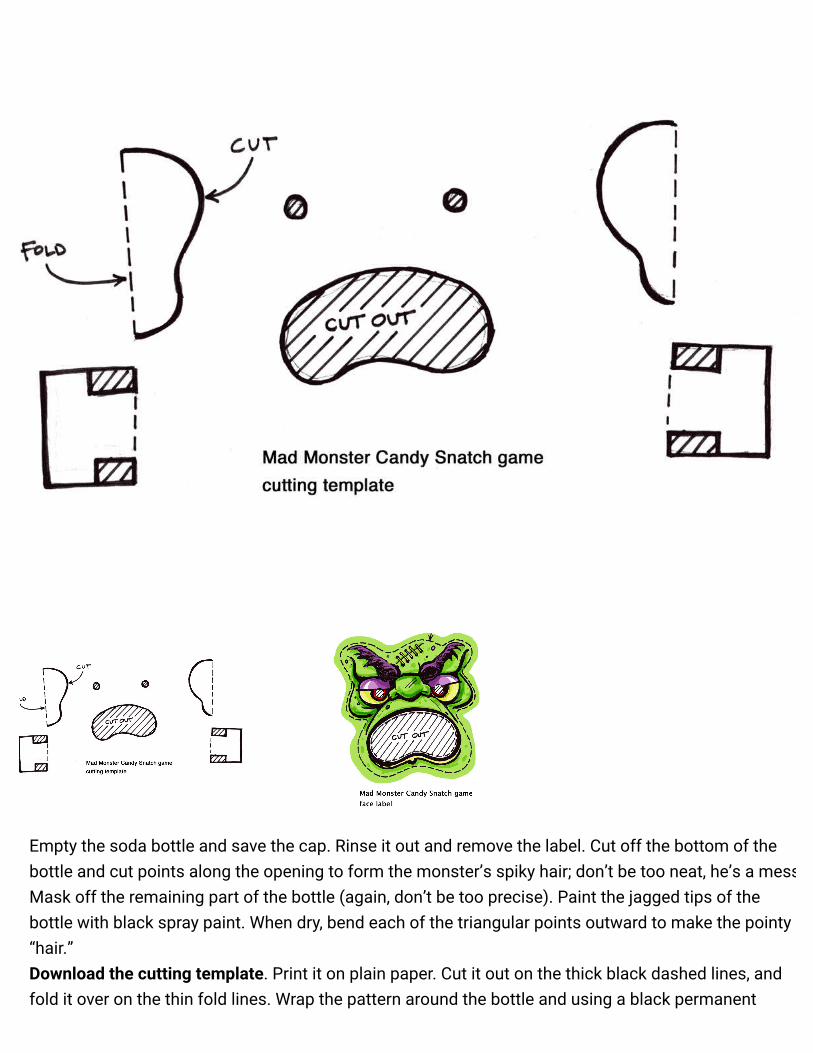
Empty the soda bottle and save the cap. Rinse it out and remove the label. Cut off the bottom of thebottle and cut points along the opening to form the monster’s spiky hair; don’t be too neat, he’s a mess!Mask off the remaining part of the bottle (again, don’t be too precise). Paint the jagged tips of thebottle with black spray paint. When dry, bend each of the triangular points outward to make the pointy“hair.”Download the cutting template. Print it on plain paper. Cut it out on the thick black dashed lines, andfold it over on the thin fold lines. Wrap the pattern around the bottle and using a black permanent

SPONSORED CONTENT
What Is the Problem With Counterfeit Toner?BY HP
marker, trace the cut lines onto the bottle. Use a hobby knife to carefully poke a starting slot. Using asharp scissors, cut along lines. Punch out the eyeholes with the 3/16" punch to �t the LEDs. Fold theears and neck bolts at 90° so they stick out.Cut a piece of aluminum tape 1/2"×6" and cut small slits 1/4" apart all along one long side. Then cutmore slits on the other long side, alternating the cuts so you don’t snip the strip all the way through.Then stick the tape to the inside edge of the mouth hole: Place the uncut center part of the tape alongthe edge, folding over onto the outside and inside of the bottle. It should create a foil-lined edge allalong the mouth opening. Cut more pieces of aluminum tape and stick to both sides of the ears andneck bolts.To �nish the head, download the face label. Print it on an adhesive label sheet and cut it out along thedotted line, being sure to cut out the eyes and mouth too. Carefully center it over the holes on the bottleand adhere it to the outside.
BOB KNETZGERBob Knetzger ([email protected]) is an inventor/designer with 30 years of experience makingfun stuff.

14 Comments MAKE Login1
Share⤤ Sort by Best
Join the discussion…
• Reply •
John Diehl • 2 years ago
Mad Monster Candy Snatch Game at Girl Fest – great project !!!
⛺
1△ ▽
• Reply •
Lalala • 2 years ago
Really excited to attempt this build. However, as a newbie to electronics, can you explain thefunction of the power transistor to me? Also, on the schematic, wouldn't the LED resistor comebefore the LEDs or is the power flowing the other direction?
1△ ▽
TexasMaker • 6 months ago
I work for a company (www.atec.com) that designs and builds aerospace equipment and we havean annual Halloween party with pumpkin carving contest. I made a version of this game as apumpkin. For the transistor, I used P/N NTE56 from Fry's and I found push lamps at a dollar store
Recommend
Share ›
Share ›

• Reply •
pumpkin. For the transistor, I used P/N NTE56 from Fry's and I found push lamps at a dollar storewith 3 LEDs that I removed from the housings for the lighted eyes. I put foil around the mouth anda pie plate inside that I bent in half to prop up the candy raising the level up past the mouth.Worked great. First place. I have been a lifetime Maker, starting at age 10 with the Radio Shack75-in-1 electronics kit, reading everything Forrest Mims III wrote on electronics and eventually anEE degree. Parents, please encourage your kids to make things by getting them the parts theyneed like mine did. We need more engineers with "the knack" for it that comes from hands onexperience playing around with hardware. Thanks MAKE Magazine for motivating the nextgeneration of hardware hackers. Link to video: http://www.atec.com/2015/10/ha...
⛺
△ ▽
• Reply •
Living Institute For Education • a year ago
We didn't have all the parts, but that didn't stop our boys...they used their Snap Circuits kit tocreate the alarm. And we used Lego Minifigs instead of candy :)
⛺
⛺
△ ▽
Daymaker Lavon • 2 years ago
We made ours, thanks for all the help Bob!
▶
Share ›
Share ›

• Reply • △ ▽
• Reply •
skbwolverine . • 6 months ago> Daymaker Lavon
Awesome! △ ▽
• Reply •
Jill Dawson • 2 years ago
I have finally figured this out and have posted the solution to my blog. Thanks for the tip about thepolarity of the speakers, Joe. http://jillericksondawson.blog...
⛺
△ ▽
• Reply •
Cheryl Lustenberger • 2 years ago
Where are the downloadable audio file you mention in the article? I've gone through the projectpage and can not find them. Thanks.
△ ▽
• Reply •
MoxieMiniMakers • 2 years ago
Household of new makers in over our heads! If anyone can explain a bit the things listed below byJill, I am not certain what to solder/how to connect the resistor and B,C and E. Ideally someonecan take up close photos of perf board (top and underneath?) and the led light parallel wiring ontheir completed project and I can copy at home. It appears I should cut off microphone fromsound board and use those wires? Photos should answer most questions I think.
My six year old and I are bound to get better over time, but inspiration is not pulling this one off!We did get our sound board soldered and hooked up so the monster "speaks" when the tweezerstouch the aluminum tape.
△ ▽
Jill Dawson • 2 years ago
I got through the gauntlet of soldering new wires to the switch pad, but I got lost when thedirections said, "Add the power transistor to the perf board and after noting the E,C,and B legs,wire up the connections to the speaker, and then solder the connections to the dropping resistorand the two LEDs." Am I supposed to solder NEW wires to the speakers? The picture shows twosets of wires there. How do I determine the polarity; both of the wires connecting to my speakerare the same color. How do the wires then connect to the transistor? I know which leg is which,
Share ›
Share ›
Share ›
Share ›
Share ›

• Reply •
are the same color. How do the wires then connect to the transistor? I know which leg is which,but I don't quite understand where to go with just that information. Am I also supposed to solderthe LED leads to the transistor? I am new to this, so I sincerely appreciate any suggestions forbetter understanding the schematic or this part of the written directions. Can anyone advise,please?
△ ▽
• Reply •
Joe • 2 years ago> Jill Dawson
If you're using the Radio Shack Sound Module, on the speaker there is a faint "+" and "-"where the leads connect to the speaker....FWIW, In my build I bypassed the transistoraltogether and added 2 wires to the speaker and sent them directly to my LEDs (with the220 resistor in the middle of course)
△ ▽
• Reply •
Jill Dawson • 2 years ago> Joe
Thanks, Joe. I'll give that a try if I can't get more explanation on the transistor. I justreally want to understand the designer's intent.
△ ▽
• Reply •
Shannon • 2 years ago
Approximate cost? Time to make? △ ▽
• Reply •
Ryan Ouradnik • 2 years ago
I did a remix of this. Made it a little simpler and added Scratch Software
https://www.facebook.com/video... △ ▽
Subscribe✉ Add Disqus to your site Add Disqus Addd Privacy�
Share ›
Share ›
Share ›
Share ›
Share ›


