32
Danfoss District Energy MAKING MODERN LIVING POSSIBLE DECS 2.0 Danfoss Energy Control System · User Guide
| Date post: | 28-Aug-2018 |
| Category: |
Documents |
| Upload: | truongkien |
| View: | 216 times |
| Download: | 0 times |

Danfoss District Energy
MAKING MODERN LIVING POSSIBLE
DECS 2.0Danfoss Energy Control System
· User Guide
DEN-SMT/DK VI.HX.A1.02 Danfoss District Energy
Table of Contents
Introduction .................................................................................................................................................................. 3DECS 2.0 3
Important product information .................................................................................................................................. 4Application examples 5Accessing the DECS 2.0 user interface 6Language selection 6User groups 7Login 8Logged in 9Logout 9
Overview menu .......................................................................................................................................................... 10Overview places 10General overview 11Quick links 11Boiler house overview 11
Customer menu .......................................................................................................................................................... 12Find a customer 12Customer selection 12Customer display 12Create customer 13Delete customer information 13Controller overview 14Controller settings 14Controller settings - Setup section 15
Configuration target values 15Main set values 15MBus units/Heating time settings 15Master/slave 16
Controller settings - Time section 16Heating time table 16Heating time table - boiler 17Heating time table - circulation pump 17Holiday - circulation - boiler load time 17
Controller settings - Administration section 18Controller display 18Application controller 18Delete controller 18Dereference controller 19Reference controller 19
Heating plant menu ................................................................................................................................................... 20Statistics menu ........................................................................................................................................................... 21
Search customer 21Customer selection 21
Evaluation (graphics) 22Evaluation (tabular) 23MBus units 24
Place statistics selection 25Overview 25Minimum consumption 25Flow management 25Quality management 25
Alarms menu ............................................................................................................................................................... 26Messages menu .......................................................................................................................................................... 27Support menu ............................................................................................................................................................. 28Administrator menu ................................................................................................................................................... 29
General settings 29User management 29
User list 30New user 30Delete user 30
Change date/time 30Software update 30
Page

Danfoss District Energy VI.HX.A1.02 DEN-SMT/DK 3
Introduction
DECS 2.0The Danfoss Energy Control System (DECS) is a web-based SCADA software solution (Supervisory Control And Data Acquisition) for district heating systems.
This SCADA solution is typically installed locally at the heating utility and will automatically configure its user interface and functionality to support the application on the controller (for example Danfoss ECL Comfort 310).
The user of the DECS 2.0 system is able to remote control and monitor the parameters settings in the controllers and also monitor actual, reference and historical values of sensors and meters connected to the controller.
Danfoss ECL Comfort 310, OPR0010 and OPR0020 controllers are supported by the auto-configuration features of DECS 2.0, but other district heating controllers, e.g. the ECL Apex 20 controller, can also be supported by manually adding graphics and programs into DECS 2.0.
This user guide is intended for operators at district heating utilities who monitor district heating in cities and/or larger plants as well as owners/operators of stand-alone district heating plants to ease the daily monitoring work. Data is constantly exchanged between controllers and the DECS 2.0 server, and configuration reports and alarm reports are generated automatically. In addition the heating station and substation installations can be controlled and monitored from everywhere, as the server provides an intuitive user interface that is accessible from any standard browser on a PC, laptop or smartphone connected to the internet.
The present user guide contains detailed explanation of the features in the DECS 2.0 system. If you need further information on controllers to be used together with the DECS 2.0 system, please see the below literature reference.
Additional technical literature related to the DECS 2.0 Danfoss Energy Control system:
* Data sheet on DECS 2.0 VD.HX.A1
* Quick guide for end users on DECS 2.0 VI.HX.B1
* Installation guide for technicians on DECS 2.0 VI.HX.C1
* Installation guide on ECL Comfort 310, application P330 VI.GU.O1

4 DEN-SMT/DK VI.HX.A1.02 Danfoss District Energy
Important product information
This User Guide is associated with the DECS 2.0 software (order code no. 187B1503, 187B1504 or 187B1505). The DECS 2.0 software can operate together with three types of District Heating controllers: OPR0010 using firmware V3.6, OPR0020 using firmware R4 to R7 and ECL Comfort 310 using P330 application key.
The DECS 2.0 visualization software can be used for three types of communication: LON, Modbus and Ethernet communication.
The DECS 2.0 system does not affect any other software or web application. DECS 2.0 does neither set requirements related to what is installed, nor to the selection of web browser or hardware.
Basically, every web browser that supports SVG, JavaScript and asynchronous http requests should work, but based on some of the build-in functionality, the following web browsers are supported:
* Firefox, Mozilla
* Internet explorer, Microsoft
* Chrome, Google
* Opera, Opera
For information on supported versions, please contact your system integrator or provider.
The DECS 2.0 server application is only built for 32-bit systems, running Windows XP or Windows 7.Please see further detailed requirements in the DECS 2.0 data sheet.
If questions arise or problems occure, please contact your system integrator or provider of the DECS 2.0 system.

Danfoss District Energy VI.HX.A1.02 DEN-SMT/DK 5
Application examples
s
p
o
o
o
o
j
j
j
n
l
q
j
k
k
l
m
m
m
m
r q r
p
o
o
o
o
j
j
j
nj
k
l
m
m
m
m
j Private house
k Communication server
l Internet
m Fieldbus: LON, Modbus, Ethernet communication
n DECS 2.0 client (external service provider/district heating end users)
o ECL Comfort 310 controller
p District heating utility
q OPC server
r SCADA client
s DESC 2.0 client (central administration)
j Private house
k Communication server + OPC
l Internet
m Fieldbus: LON, Modbus, Ethernet communication
n DECS 2.0 client (external service provider/district heating end users)
o ECL Comfort 310 controller
p District heating utility
q SCADA client
r DESC 2.0 client (central administration)
Above is an application example showing the DECS 2.0 system distributed in several sub-systems.
Above is an application example of a locally centralized communication system.
j
j
j
nl
k
m
p
q
o
j Private house
k District heating utility
l Modbus-RS485 network
m Internet
n Communication server, SCADA, OPC
o DECS 2.0 client (external service provider/district heating end users)
p DESC 2.0 client (central administration)
q ECL Comfort 310 controller
Above is an application example showing all sub-systems installed on one localized server at the district heating utility.

Danfoss District Energy VI.HX.A1.02 DEN-SMT/DK 6
Accessing the DECS 2.0 user interface
To operate the DECS 2.0 software its user interface must be accessed using one of the web browsers mentioned earlier.
Open the web browser and enter the IP address of the DECS 2.0 server in the address field. The user interface will then be shown in the web browser. If you need help re. the IP address, please contact your network administrator.
Alternatively, the system integrator or IT administrator may have assigned a domain name to the DECS 2.0 server. In this case the domain name (URL) should be entered into the address field of the web browser instead of the IP address.
Language selection
All users have registered a default user language.
The language can though be changed simply by pressing the ‘Language selection’ button next to the date. This selection will overwrite the originally set default user language.
There are 3 languages available: English, German and Italian.
All selections have to be made again if the language has been changed during operation.
Language selection is independent of the default user language settings, meaning that the default user language is only present if language has not been selected by the user.

Danfoss District Energy VI.HX.A1.02 DEN-SMT/DK 7
User groups
The following user groups are available on the SCADA system with different application rights:
Group A Super user Can handle all menus
Group B Service engineer Can handle all menus
Group C System engineer Can handle all menus except the administration menu
Group D Staff member Can handle all menus except the administration menu
Group E Operator Besides the attributes, which are needed for all users of a given group, when you enlarge the system with a user within the group ‘Operator’, you have to additionally define the following attribute: ‘City’ of the DECS 2.0 system. Therefore, when a given operator is logged into the system, the operator can only see the belonging city and nothing else.
Group F Customer Besides the attributes, which are needed for all users of a given group, when you enlarge the system with a user within the group ‘Customer’, you have to additionally define the following attributes: ‘City’ and ‘Customer’ of the DECS 2.0 system. Therefore, when a given customer is logged into the system, the customer can only see the belonging customer and nothing else.
Supe
rUser
ServiceEng
ineer
System
Engine
er
StaffM
embe
r
Ope
rator
Custom
er
Overview √ √ √ √Customer √ √ √ √ √- create/change/delete √ √ √ √ √- regulator overview Read √ √ √ √ √ √
Change √ √ √ √ √ √- regulator create √ √ √ √ √- regulator delete √ √ √ √ √- regulator show √ √ √ √ √ √- regulator reference / dereference √ √ √ √ √- configuration target values Read √ √ √ √ √
Change √ √ √ √ √- main set values Read √ √ √ √ √
Change √ √ √ √ √- heating time-table Read √ √ √ √ √ √
Change √ √ √ √ √ √- MBus units settings Read √ √ √ √ √
Change √ √ √ √ √- controller Master/Slave (ECL310) √ √ √ √ √BoilerHouse √ √ √ √ √Statistics √ √ √ √ √ √- Customer common statistics MBus-unit √ √ √ √ √ √
Evaluation (text) √ √ √ √ √ √Evaluation (graphic) √ √ √ √ √ √Special statistic:Sonometer 1000 √ √ √ √ √ √
- General statistics Flow ratemanagement √ √ √ √ √Overview √ √ √ √ √Minimum consumption √ √ √ √ √Quality management √ √ √ √ √
Alert √ √ √ √Information √ √ √ √Support √ √ √ √ √ √Administrator √ √

8 DEN-SMT/DK VI.HX.A1.02 Danfoss District Energy
Login
To login press the ‘Login’ button in the lower right corner.
When pressing this button you will be asked to enter your username and password in a new pop-up window.
There is one default user included in the DECS 2.0 software. The installer of the DECS 2.0 software can use this default user to create at least one user in the system after deploying the software.
If only the default user is available in the system, please ask the system integrator to include a new user.
If a wrong username or password is entered, a message will be shown.

Danfoss District Energy VI.HX.A1.02 DEN-SMT/DK 9
Logout
Logged in
When you are logged in, the green button in the lower right corner changes to red.
After login the function of the login button changes to a logout function.
By pressing the button you will logout of the system and return to the main display.
Logout will also occur if the web page for DECS 2.0 is closed. In addition, logout will occur after a set time of inactivity.
When logout is executed this will not affect any data communication, meaning the system will continue retrieving data from the district heating controller; data will keep being processed.
Logout will only prevent you from viewing and monitoring any district heating grid information.
10 DEN-SMT/DK VI.HX.A1.02 Danfoss District Energy
Menus
The DECS 2.0 software is divided into 8 sections:
1. Overview: Quick overview of the district heating grid
2. Customer: Customer information and monitoring possibilities
3. Heating plant: To include heating plant displays, including the attached available information
4. Statistics: Graphical and tabular statistics information
5. Alarm: For monitoring alarms coming from the district heating controllers
6. Messages: For monitoring information related to the DECS 2.0 software
7. Support: Support related to the DECS 2.0 software, district heating controllers, district heating grid
8. Administrator: Adding new places, heat meter read-out data selection, user management of DECS 2.0, updating time stamp for the district heating controllers. Software update for controllers that support remote software update.
Overview menu
This menu gives you a quick overview of the district heating grid.The display is divided into 4 sections:
1. Overview places2. General overview3. Quick links4. Boiler house overview
j j
k
l
m
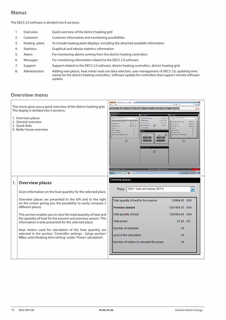
1. Overview places
Gives information on the heat quantity for the selected place.
Overview places are presented to the left and to the right on the screen giving you the possibility to easily compare 2 different places. This section enables you to view the total quantity of heat and the quantity of heat for the present and previous season. This information is only presented for the selected place.
Heat meters used for calculation of the heat quantity are selected in the section: ‘Controller settings - Setup section/MBus units/Heating time setting’ under ‘Power calculation’.

Danfoss District Energy VI.HX.A1.02 DEN-SMT/DK 11
2. General overview
This section gives the same information as in overview places. Here the heat quantity is summarized for all places.
3. Quick links
Fast entry into heat meter overview and min. consumption.
4. Boiler house overview
Is an optional section and can include information related to boiler house information.
12 DEN-SMT/DK VI.HX.A1.02 Danfoss District Energy
Customer menu
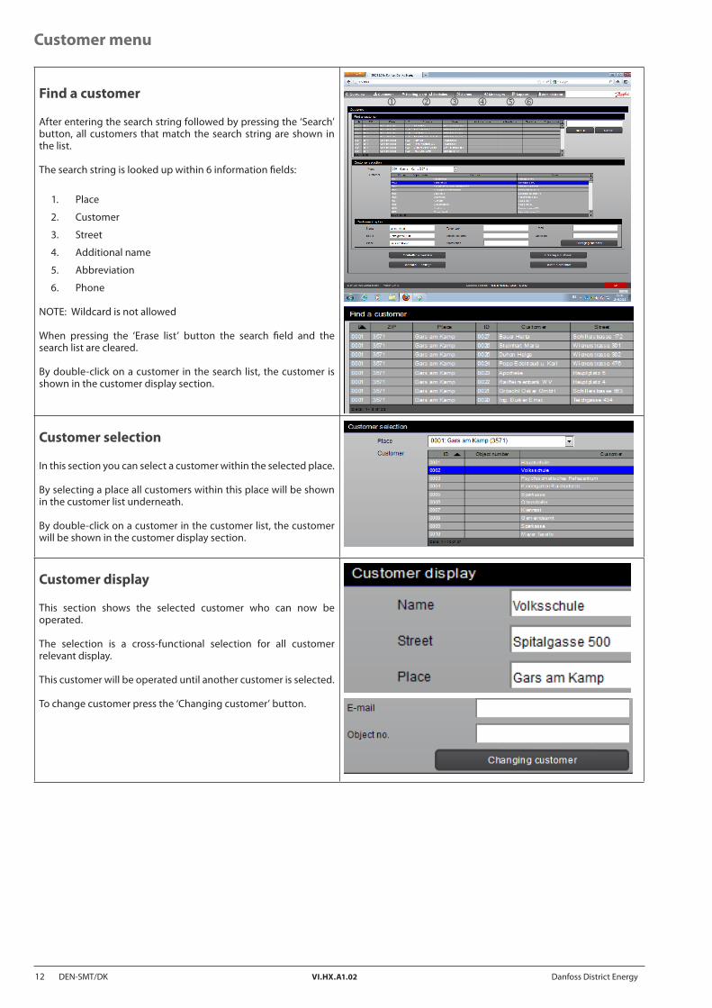
Find a customer
After entering the search string followed by pressing the ‘Search’ button, all customers that match the search string are shown in the list.
The search string is looked up within 6 information fields:
1. Place
2. Customer
3. Street
4. Additional name
5. Abbreviation
6. Phone
NOTE: Wildcard is not allowed
When pressing the ‘Erase list’ button the search field and the search list are cleared.
By double-click on a customer in the search list, the customer is shown in the customer display section.
oj k l m n
Customer selection
In this section you can select a customer within the selected place.
By selecting a place all customers within this place will be shown in the customer list underneath.
By double-click on a customer in the customer list, the customer will be shown in the customer display section.
Customer display
This section shows the selected customer who can now be operated.
The selection is a cross-functional selection for all customer relevant display.
This customer will be operated until another customer is selected.
To change customer press the ‘Changing customer’ button.
Danfoss District Energy VI.HX.A1.02 DEN-SMT/DK 13
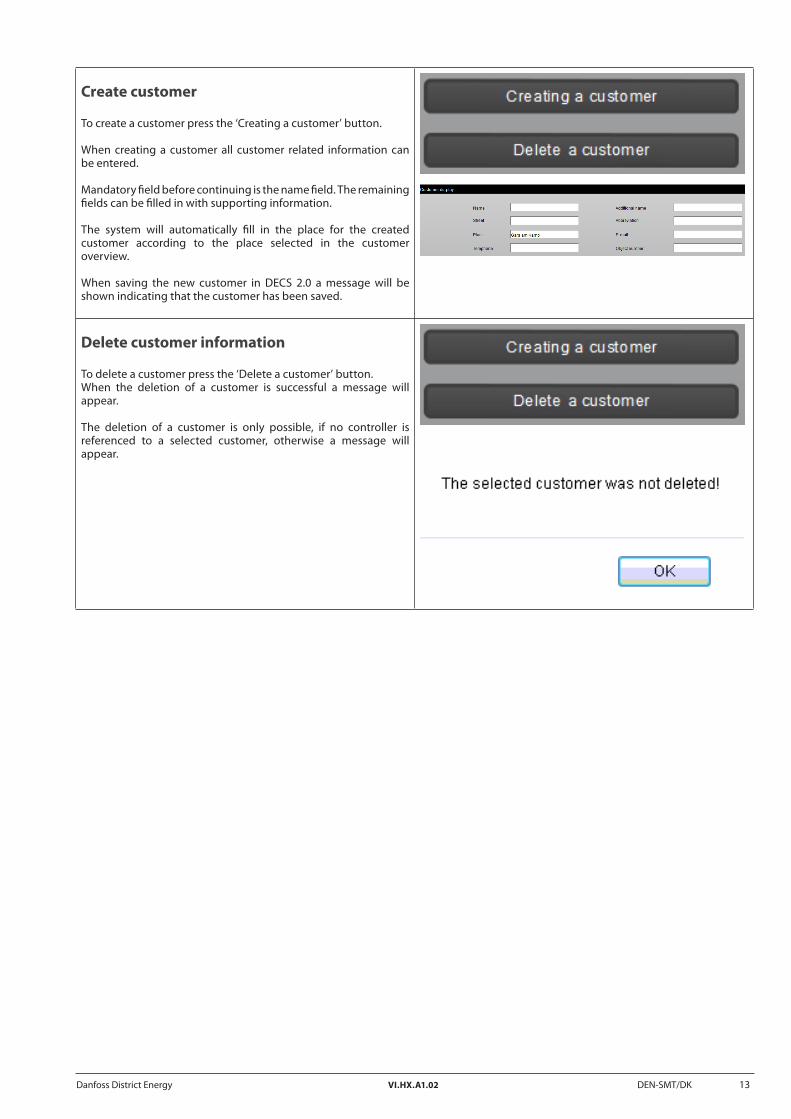
Create customer
To create a customer press the ‘Creating a customer’ button.
When creating a customer all customer related information can be entered.
Mandatory field before continuing is the name field. The remaining fields can be filled in with supporting information.
The system will automatically fill in the place for the created customer according to the place selected in the customer overview.
When saving the new customer in DECS 2.0 a message will be shown indicating that the customer has been saved.
Delete customer information
To delete a customer press the ‘Delete a customer’ button. When the deletion of a customer is successful a message will appear.
The deletion of a customer is only possible, if no controller is referenced to a selected customer, otherwise a message will appear.

14 DEN-SMT/DK VI.HX.A1.02 Danfoss District Energy
Controller overview
When pressing the ‘Controller - overview’ button, an overview of the installation for this specific customer is shown.
The available information on the overview pictures might differ depending on the installed district heating controller and on which application the controller is running.
The default presented circuits for ECL Comfort 310 are depending on the application that is installed on the district heating controller.
The default presented circuits for OPR0010 and OPR0020 are depending on the settings generated in the DECS 2.0 software.
Using the DECS 2.0 solution, it might also be possible to make the overview pictures for an ECL Comfort 310 fit the real installation. This is done under ‘Controller - settings’.
Before creating the picture dynamically, settings are read out from the controller and used for default picturing.
NOTE: Because of this the controller must be reachable before implementing the controller in the DECS 2.0 solution.
Controller settings
To get an overview of the controller settings press the ‘Controller - settings’ button.
The selected customer is shown in the list on the top of the display.
All attached controllers to this specific customer are shown in the list.
The active selected controller is shown.Controller number is added in the ‘Active controller’ section.
Default: The first controller from the list is selected.
The controller settings are divided into 3 sections:
1. Setup
2. Time
3. Administration
The availability of this function depends on which controller is selected.
If the function of the button is not available for the selected controller a message will be shown.
j lk
15 DEN-SMT/DK VI.HX.A1.02 Danfoss District Energy
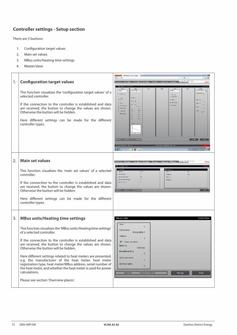
Controller settings - Setup section
There are 5 buttons:
1. Configuration target values
2. Main set values
3. MBus units/Heating time settings
4. Master/slave
1. Configuration target values
This function visualizes the ‘configuration target values’ of a selected controller.
If the connection to the controller is established and data are received, the button to change the values are shown. Otherwise the button will be hidden.
Here different settings can be made for the different controller types.
2. Main set values
This function visualizes the ‘main set values’ of a selected controller.
If the connection to the controller is established and data are received, the button to change the values are shown. Otherwise the button will be hidden.
Here different settings can be made for the different controller types.
3. MBus units/Heating time settings
This function visualizes the ‘MBus units/Heating time settings’ of a selected controller.
If the connection to the controller is established and data are received, the button to change the values are shown. Otherwise the button will be hidden.
Here different settings related to heat meters are presented, e.g. the manufacturer of the heat meter, heat meter registration type, heat meter/MBus address, serial number of the heat meter, and whether the heat meter is used for power calculations.
Please see section ‘Overview places’.
Danfoss District Energy VI.HX.A1.02 DEN-SMT/DK 16
4. Master/slave
In this section you can define the master/slave settings of ECL Comfort 310 controllers.
By defining a master you will have the possibility to link slaves to the master.
With this functionality you can define that the slave controller has to change certain values (outdoor temperature and resulted target temperature) via the OPC server if the communication type of the controller is TCP/IP or ModBus.
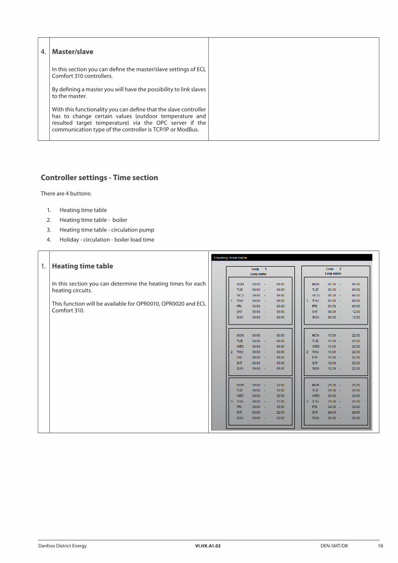
Controller settings - Time section
There are 4 buttons:
1. Heating time table
2. Heating time table - boiler
3. Heating time table - circulation pump
4. Holiday - circulation - boiler load time
1. Heating time table
In this section you can determine the heating times for each heating circuits.
This function will be available for OPR0010, OPR0020 and ECL Comfort 310.

Danfoss District Energy VI.HX.A1.02 DEN-SMT/DK 17
2. Heating time table - boiler
In this section you can determine the heating times for each boiler.
This function is not available for OPR0010.
3. Heating time table - circulation pump
In this section you can determine the circulation times for the circulation pump to circulate hot water.
This function is only available for ECL Comfort 310.
4. Holiday - circulation - boiler load time
In this display the holiday, circulation and boiler load times of a selected controller are visualized.
Here you can determine the time for the controller to go into holiday mode and whether the controller automatically shall switch between winter and summer time.
You can also select the language of the controller, boiler charging time, duration of water circulation including the time duration and which days to start the water circulation.
This functionality is not available for ECL Comfort 310.
18 DEN-SMT/DK VI.HX.A1.02 Danfoss District Energy
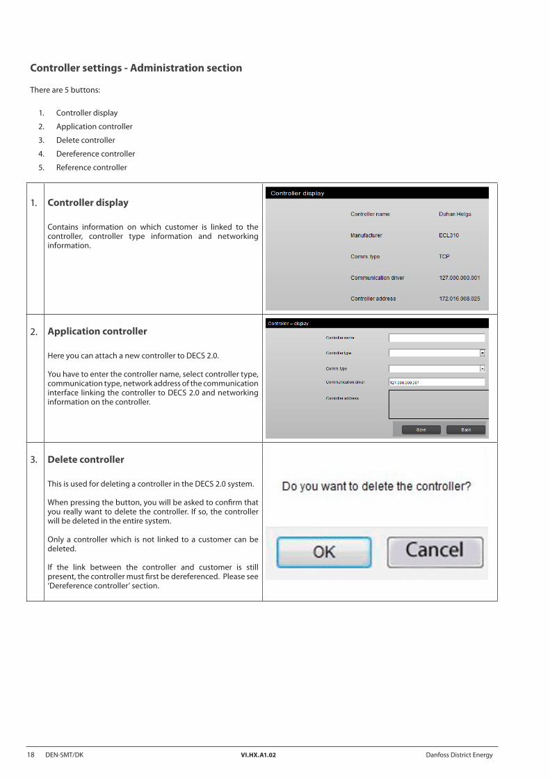
Controller settings - Administration section
There are 5 buttons:
1. Controller display
2. Application controller
3. Delete controller
4. Dereference controller
5. Reference controller
1. Controller display
Contains information on which customer is linked to the controller, controller type information and networking information.
2. Application controller
Here you can attach a new controller to DECS 2.0.
You have to enter the controller name, select controller type, communication type, network address of the communication interface linking the controller to DECS 2.0 and networking information on the controller.
3. Delete controller
This is used for deleting a controller in the DECS 2.0 system.
When pressing the button, you will be asked to confirm that you really want to delete the controller. If so, the controller will be deleted in the entire system.
Only a controller which is not linked to a customer can be deleted.
If the link between the controller and customer is still present, the controller must first be dereferenced. Please see ‘Dereference controller’ section.

Danfoss District Energy VI.HX.A1.02 DEN-SMT/DK 19
4. Dereference controller
Here you can break the link between a customer and a controller.
By dereferencing the controller will still be present in the system, and the controller will also be asked for data, e.g. heat meter data.
5. Reference controller
Here you can establish the link between a controller and the selected customer before entering the display.
20 DEN-SMT/DK VI.HX.A1.02 Danfoss District Energy
Heating plant menu
This is an option to be used for including boiler house presentation. Here you can integrate third party components based on OPC standard communication.
Questions related to this section must be directed to the system integrator.

Danfoss District Energy VI.HX.A1.02 DEN-SMT/DK 21
The statistics display is meant to be used for visualization of historical data.
The selected customer from the ‘Customer menu’ is automatically imported into the statistics display. The statistics display is divided into 3 sections.
1. Search customer
2. Customer selection
3. Place statistics selection
In the bottom of the display, you can push the button ‘Switch to customer overview’ which brings you directly to the controller overview according to the selection in the ‘Customer selection’ section.
1. Search customer
This section shows the selected customer who can now be operated.
The selection is a cross-functional selection for all customer relevant display.
This customer will be operated until another customer is selected.
To change customer press the ‘Changing customer’ button.
2. Customer selection
The customer selection section is divided into two sections.
First the customer is selected and then a controller for this customer is selected, for which the statistic wants to be visualized.
If only one controller is linked to a customer then this controller is automatically selected. The controller is selected when it is shown in the ‘Customer display’.
Hereafter three kinds of statistics can be selected:
A. Evaluation (graphics)
B. Evaluation (tabular)
C. MBus units
A B C
Statistics menu

22 DEN-SMT/DK VI.HX.A1.02 Danfoss District Energy
A. Evaluation (graphics)
Evaluation (graphics) will present the historically data in a graph.
Here you can select a given sensor or heat meter for which you want the historically data to be evaluated. The display is divided into 4 sections:
1. Time period Select the time period for which you want to evaluate the historical data.
2. Controller data points
Double-click on the sensor which you want to evaluate. The sensor is selected when the line is marked with a blue colour (double-click).
3. Heat meter Select the type of heat meter you want to evaluate. Only the type which has been selected on the controller can be selected.
4. Press buttons When selection has been made, press the button ‘Adjust graphics’ to get the graph presented. When moving the mouse over the graph the trace function is activated, giving the information of the values for a given time and date together with which sensor or heat meter.The print button will make it possible to print out the graph shown together with the sensor and selected heat meter information.
Up to 10 data selections can be made either in combination or individually.
To remove the selection of a sensor or heat meter data point, simply double-click on the data point.
j
k
m
l
Danfoss District Energy VI.HX.A1.02 DEN-SMT/DK 23
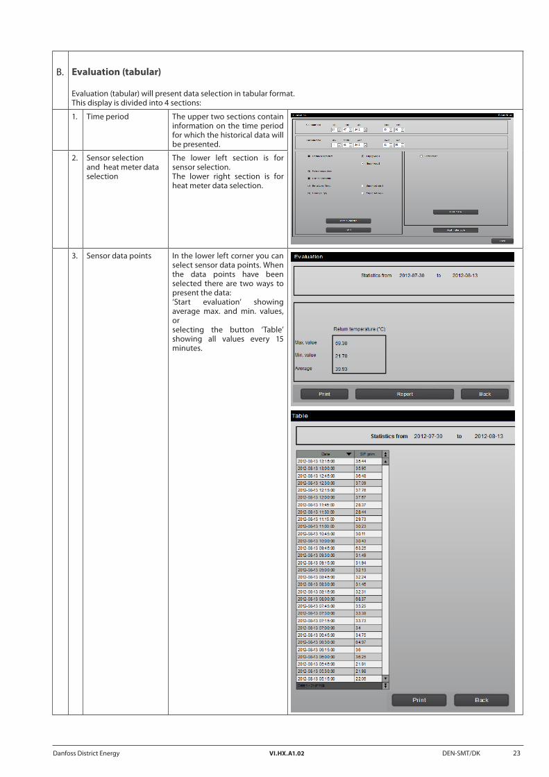
B. Evaluation (tabular)
Evaluation (tabular) will present data selection in tabular format. This display is divided into 4 sections:
1. Time period The upper two sections contain information on the time period for which the historical data will be presented.
2. Sensor selection and heat meter data selection
The lower left section is for sensor selection. The lower right section is for heat meter data selection.
3. Sensor data points In the lower left corner you can select sensor data points. When the data points have been selected there are two ways to present the data: ‘Start evaluation’ showing average max. and min. values, or selecting the button ‘Table’ showing all values every 15 minutes.
24 DEN-SMT/DK VI.HX.A1.02 Danfoss District Energy
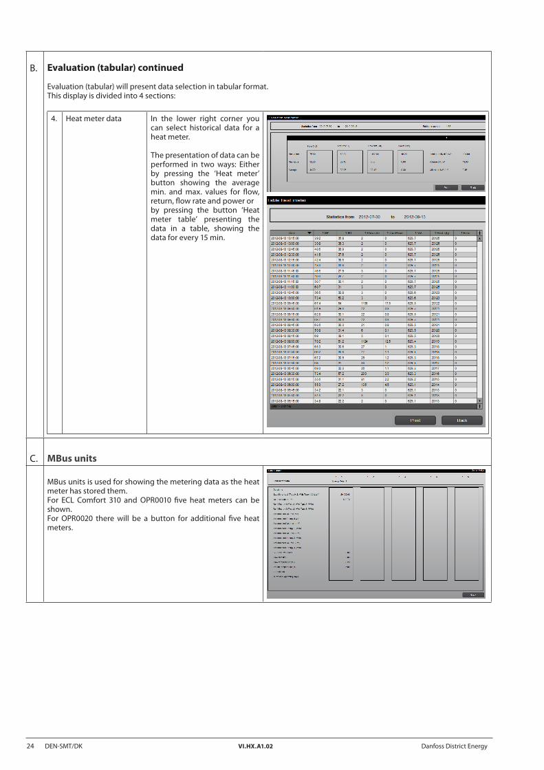
B. Evaluation (tabular) continued
Evaluation (tabular) will present data selection in tabular format. This display is divided into 4 sections:
4. Heat meter data In the lower right corner you can select historical data for a heat meter.
The presentation of data can be performed in two ways: Either by pressing the ‘Heat meter’ button showing the average min. and max. values for flow, return, flow rate and power or by pressing the button ‘Heat meter table’ presenting the data in a table, showing the data for every 15 min.
C. MBus units
MBus units is used for showing the metering data as the heat meter has stored them. For ECL Comfort 310 and OPR0010 five heat meters can be shown. For OPR0020 there will be a button for additional five heat meters.

Danfoss District Energy VI.HX.A1.02 DEN-SMT/DK 25
1. Place statistics selection
In the place statistics selection section 4 kinds of place statistics can be selected:
1. Overview By selecting a heat meter and a place followed by pressing the button ‘Refresh’ a general overview will be shown (Reachability of the controller, different heat meter data, the mode in which the controller is running etc.). From here you can also go directly to the controller overview display, simply by double-clicking a controller (marking the line blue) and pressing the button ‘Controller overview.’The display shows a legend in the button of the display as a guide for the different columns.The information in the table can be printed out by pressing the ‘Print’ button.
2. Minimum consumption
By selecting a place different statistics are shown. Controller information, name of the customer, power used since last billing, total power used until now, difference between used power now and since last billing, how often these heat meter data are collected together with the maximum power that shall be delivered, if agreed.These data can be printed out by pressing the ‘Print’ button.
3. Flow management
By selecting a place different statistics are shown relating to the district heating flow. These data can be printed out by pressing the ‘Print’ button.
4. Quality management
By selecting a place different statistics are shown. These data are related to consumption, volume in m, when the heat meter was last read and the consumed power.These data can be printed out by pressing the ‘Print’ button.

26 DEN-SMT/DK VI.HX.A1.02 Danfoss District Energy
Here you can select a place and see all the present and old alarms.
You will be able to attach a date filter, e.g. only alarms within the last 14 days will be shown. By double-clicking the alarm is selected and can be acknowledged.
When an alarm has been acknowledged, a message will appear. The login user will be registered for acknowledging the alarm. This information will be written to the row of the specific alarm.
Alarms that have been acknowledged will not be deleted from the list.
Alarms menu
Danfoss District Energy VI.HX.A1.02 DEN-SMT/DK 27
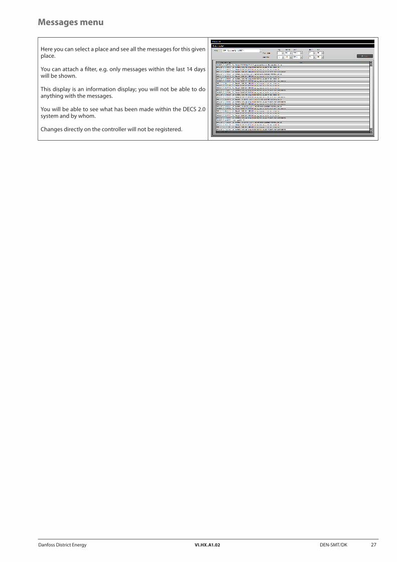
Here you can select a place and see all the messages for this given place.
You can attach a filter, e.g. only messages within the last 14 days will be shown.
This display is an information display; you will not be able to do anything with the messages.
You will be able to see what has been made within the DECS 2.0 system and by whom.
Changes directly on the controller will not be registered.
Messages menu

28 DEN-SMT/DK VI.HX.A1.02 Danfoss District Energy
Support menu
Here you will be linked to your system integrator or provider of the DECS 2.0 system.

Danfoss District Energy VI.HX.A1.02 DEN-SMT/DK 29
There are 3 buttons:
1. General settings
2. User management
3. Change date/time
4. Software update (only visible for OPR0020 controllers)
1. General settings
Here you can delete and create places used in DECS 2.0. When deleting a place, all controllers must be deleted before doing so. Here you can also administrate the controller meter reading day settings.
2. User management
Here you will be able to administrate login into the DECS 2.0 system.
The name or password for the users cannot be changed after the creation. If you want to do so, the user has to be deleted and created again.
There are 3 buttons:
A. User list
B. New user
C. Delete user
Administrator menu
30 DEN-SMT/DK VI.HX.A1.02 Danfoss District Energy
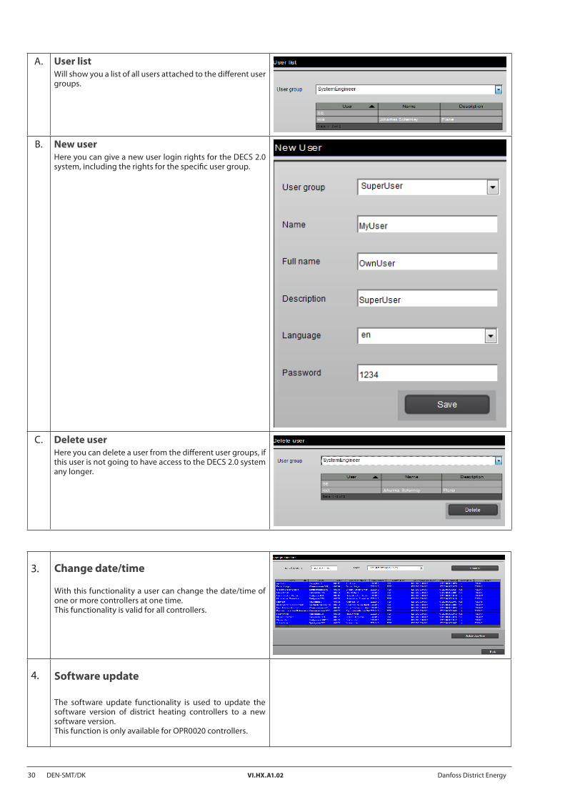
A. User listWill show you a list of all users attached to the different user groups.
B. New userHere you can give a new user login rights for the DECS 2.0 system, including the rights for the specific user group.
C. Delete userHere you can delete a user from the different user groups, if this user is not going to have access to the DECS 2.0 system any longer.
3. Change date/time
With this functionality a user can change the date/time of one or more controllers at one time. This functionality is valid for all controllers.
4. Software update
The software update functionality is used to update the software version of district heating controllers to a new software version.This function is only available for OPR0020 controllers.

Danfoss District Energy VI.HX.A1.02 DEN-SMT/DK 31
32 DEN-SMT/DK VI.HX.A1.02 © Danfoss 11/2012 Danfoss District Energy
✐
*087H9108**VIHXA102*


![DECS Principles of Improvement & Effectiveness DECS School Self Study Template Site Improvement Case Study: [school name]](https://static.documents.pub/doc/80x56/56649f1c5503460f94c32c01/decs-principles-of-improvement-effectiveness-decs-school-self-study-template.jpg)


