15
Making the ATF into an ERL-FFAG May 27, 2015 Stephen Brooks, eRHIC R&D retreat 1 In relation to eRHIC risks addressed
| Date post: | 14-Dec-2015 |
| Category: |
Documents |
| Upload: | aubrey-lane |
| View: | 214 times |
| Download: | 0 times |
Making the ATF into an ERL-FFAG
May 27, 2015 Stephen Brooks, eRHIC R&D retreat 1
In relation to eRHIC risks addressed

Approximate Site Layout (Dejan)
May 27, 2015 Stephen Brooks, eRHIC R&D retreat 2
App
rox.
30m
Up to 150MeV injector linac Up to 300MeV
ERL linac
Use the ATF linac repeatedly e.g. 4 times to obtain higher energies and test ERL-FFAG principle

Scaling type(by factor a) Length Angle Dipole Gradient Quad offset (=dipole/grad)
& orbit excursion
Momentum (~energy) 1 1 a a 1
Machine radius a 1 a-1 a-2 a
FFAG beta length (fixed bend radius, fixed cell tune)
a a 1 a-2 a2
FFAGarc-to-straight(=row 3/row 2)
1 a a 1 a
FFAG radius with fixed orbit excursion and field (row 2*row 1/sqrt(row 3))
a1/2 a-1/2 1 1 1
FFAG scaling* laws* not scaling FFAG laws
May 27, 2015 Stephen Brooks, eRHIC R&D retreat 3
I’m going to use this one and the optimised 10.5m diameter C cell as a start.

C-like Cell (can use iron)
May 27, 2015 Stephen Brooks, eRHIC R&D retreat 4
50 MeV injector 200 MeV linac
Energies (MeV) 250, 450, 650, 850
Bending diameter 30 m
Orbit max range 32.8 mm
Max field on orbit 0.732 T
Quad gradients QF: -42.54 T/mBD: 27.493 T/m
Cell length 55.76 cm
TOF range (rel.) 1.402 × 10⁻³
cm grid
Can extract 1.05 GeV in non-ERL mode

Superimposed on ATF area
May 27, 2015 Stephen Brooks, eRHIC R&D retreat 5
• Racetrack with matching section• 84 cells per half turn
Transverse exaggeration x128

Magnet Options
May 27, 2015 Stephen Brooks, eRHIC R&D retreat 6
PM
Iron
Holger Witte’s quadrupole using iron poles
Pure permanent magnet with rotatable rods (BD shown), or Halbach quad
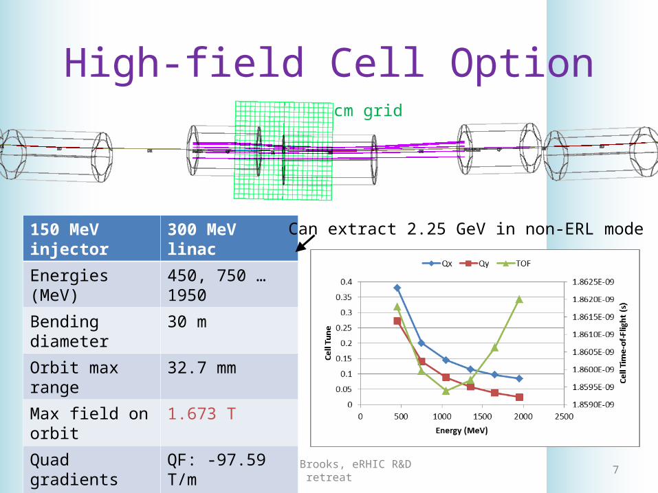
High-field Cell Option
May 27, 2015 Stephen Brooks, eRHIC R&D retreat 7
150 MeV injector 300 MeV linac
Energies (MeV) 450, 750 … 1950
Bending diameter 30 m
Orbit max range 32.7 mm
Max field on orbit 1.673 T
Quad gradients QF: -97.59 T/mBD: 63.07 T/m
Cell length 55.76 cm
TOF range (rel.) 1.403 × 10⁻³
cm grid
Can extract 2.25 GeV in non-ERL mode
Achievable with Halbach Magnets?
• No• The B=Br ln(Rout/Rinner) law is only for dipoles!
– It was tempting to think we could get arbitrarily high-field quads using the log term
• As our FFAG magnets are predominantly quadrupoles, the ~1.6T pole tip fields do not look achievable using permanent magnets– Or at least that is what my code is telling me
May 27, 2015 Stephen Brooks, eRHIC R&D retreat 8

Cost/Components Scaling
• The 850MeV 4-turn ATF design uses exactly the same magnet cross-sections as C– Beamline length increased by 30/10.5 = 2.86x– Also applies to PM volume, as packing factor same
• Rough cost scaling: C is $5-10M/10m diam. FFAG, eRHIC is $50-100M/1km, so sqrt law– Expect $8-17M for ATF FFAG loop
• Cheaper “just a line of magnets” expt possible
May 27, 2015 Stephen Brooks, eRHIC R&D retreat 9
ATF Normal-Conducting Linac
• ATF linac cannot run CW– Maximum bunch train length so far: 3us (~6 turns)– 10us might be possible (~20 turns)– Limited by RF modulators (Marcus Babzien)– Need 8+ turns to establish multi-turn ERL pattern!
• Can have up to 100 bunches in train period• Bunch length 100fs – 6ps (0.03–1.8mm)
– No problems with charge, size etc.
May 27, 2015 Stephen Brooks, eRHIC R&D retreat 10

My View of eRHIC Risk
• 3 chained amplifiers for errors and noise• Messy, real-world inputs (surprise potential)May 27, 2015 Stephen Brooks, eRHIC R&D retreat 11
Permanent magnets
Beam dynamics
High-Q cavities
Field errors
Beam position errors
E field kicks
Alignment, construction and material errors, temperature dependence
Ground vibration spectrum, BPM/corrector noise, halo from source, pipe impedances
Correctors

Commonality of ATF-FFAG with C
• The linac and RF are already available– Major cost advantage over “green field” machine
• First ever ERL-FFAG• First ever PM-based FFAG (of this size anyway)• Record NS-FFAG energy range of ~4x
– Similar to eRHIC FFAG1, similar tune range, similar orbit excursion, similar chromaticity per cell
• Real, complete tests of single particle optics
May 27, 2015 Stephen Brooks, eRHIC R&D retreat 12

Differences of ATF-FFAG with C
• Main: ATF is not a CW superconducting linac– No high-Q cavity coupled to the system
• Can’t study BBU or any other modes coupled via cavity
– Energy recovery unlikely to reach equilibrium state
• ATF-FFAG energy is higher (850 vs. 286MeV)– Might be able to measure synchrotron emission
• ATF FFAG cells are longer by 1.69x– Helps with engineering, less magnet interference
May 27, 2015 Stephen Brooks, eRHIC R&D retreat 13

Funding Profile Risk
May 27, 2015 Stephen Brooks, eRHIC R&D retreat 14
CD-0Now
Construction
CD-1
$100Ms/year
$10Ms/year on-project R&DBut not enough time
$1Ms/year C-AD R&D (not enough)
CD-3 CD-4
Spacing of CDs based on NSLS-II
Conclusion(?)
• This is really for group to decide• ERL-FFAGs are a new class of accelerator
– C=3.8km is quite large for the prototype– Building a small one first seems a sane approach
• C addresses more issues for eRHIC only• ATF-FFAG has a great deal of synergy with
eRHIC and might choose it if desire for ATF upgrade explicitly weighted into consideration
May 27, 2015 Stephen Brooks, eRHIC R&D retreat 15


