1 Optical Test Toolkit Module Optical T est T oolkit Module for the MTT and xDSL Family of Products MAN-22412-US001 Rev. C00 302 Enzo Drive San J ose, CA 95138 T el: 1-408-363-8000 Fax: 1-408-3 63-8313 User’s Manual SSMTT-33M
Transcript
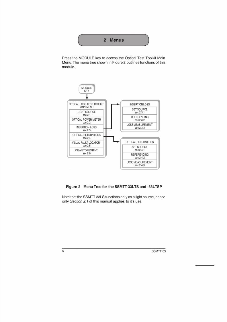
1Optical Test Toolkit Module
Optical Test Toolkit Module
for the MTT and xDSL
Family of Products
MAN-22412-US001 Rev. C00
302 Enzo Drive San Jose, CA 95138
Tel: 1-408-363-8000 Fax: 1-408-363-8313
User’s Manual
SSMTT-33M
2 SSMTT-33
WarningUsing the supplied equipment in a manner not specified by SunriseTelecom may impair the protection provided by the equipment.
CAUTIONS!• Do not remove or insert the module while the test set is on. Inserting or re -
moving a module with the power on may damage the module.• Do not remove or insert the software cartridge while the test set is on. Oth -
erwise, damage could occur to the cartridge.
End of Life Recycling and Disposal InformationDO NOT dispose of Waste Electrical and Electronic Equipment
(WEEE) as unsorted municipal waste. For proper disposal returnthe product to Sunrise Telecom. Please contact our local offices
or service centers for information on how to arrange the returnand recycling of any of our products.
EC Directive on Waste Electrical and Electronic Equip-
ment (WEEE)The Waste Electrical and Electronic Equipment Directive aims tominimize the impact of the disposal of electrical and electronic
equipment on the environment. It encourages and sets criteriafor the collection, treatment, recycling, recovery, and disposal ofwaste electrical and electronic equipment.
2010 Sunrise Telecom Incorporated. All rights reserved.
Disclaimer: Contents subject to change without notice and arenot guaranteed for accuracy.
3Optical Test Toolkit Module
Optical Test Toolkit Module Table of Contents
1 Optical Test Toolkit Module ................................................51.1 Module Panel .....................................................................51.2 Test Set LEDs ....................................................................5
2.2 Optical Power Meter ..........................................................82.3 Insertion Loss ..................................................................12
2.3.1 Set Source ....................................................................122.3.2 Referencing ..................................................................13
2.3.3 Loss Measurement .......................................................152.4 Optical Return Loss .........................................................172.4.1 Set Source ....................................................................17
2.4.2 Referencing ..................................................................172.4.3 Loss Measurement .......................................................17
2.6.1 Saving a Test ................................................................222.6.2 Viewing a Stored Test ...................................................22
2.6.3 Printing a Stored Test ...................................................222.6.4 Deleting a Stored Test ..................................................222.6.5 Locking & Unlocking a Stored Test ...............................22
2.6.6 Renaming a Stored Test ...............................................23
3.1 Fault Location and Cable ID ............................................243.2 LED Laser Source ...........................................................25
3.3 Loss Test (Power Meter + Laser Source) .........................253.3.1 STT to MTT ..................................................................25
3.3.2 MTT to MTT ..................................................................253.3.3 Optical Return Loss Test ..............................................26
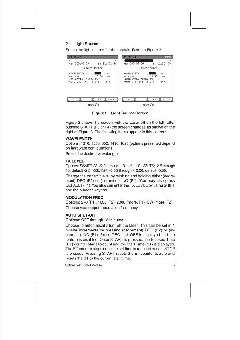
Choose to automatically turn off the laser. This can be set in 1
minute increments by pressing (decrement) DEC (F2) or (in-crement) INC (F4). Press DEC until OFF is displayed and the
feature is disabled. Once START is pressed, the Elapsed Time(ET) counter starts to count and the Start Time (ST) is displayed.The ET counter stops once the set time is reached or until STOP
is pressed. Pressing START resets the ET counter to zero andresets the ST to the current start time.
8 SSMTT-33
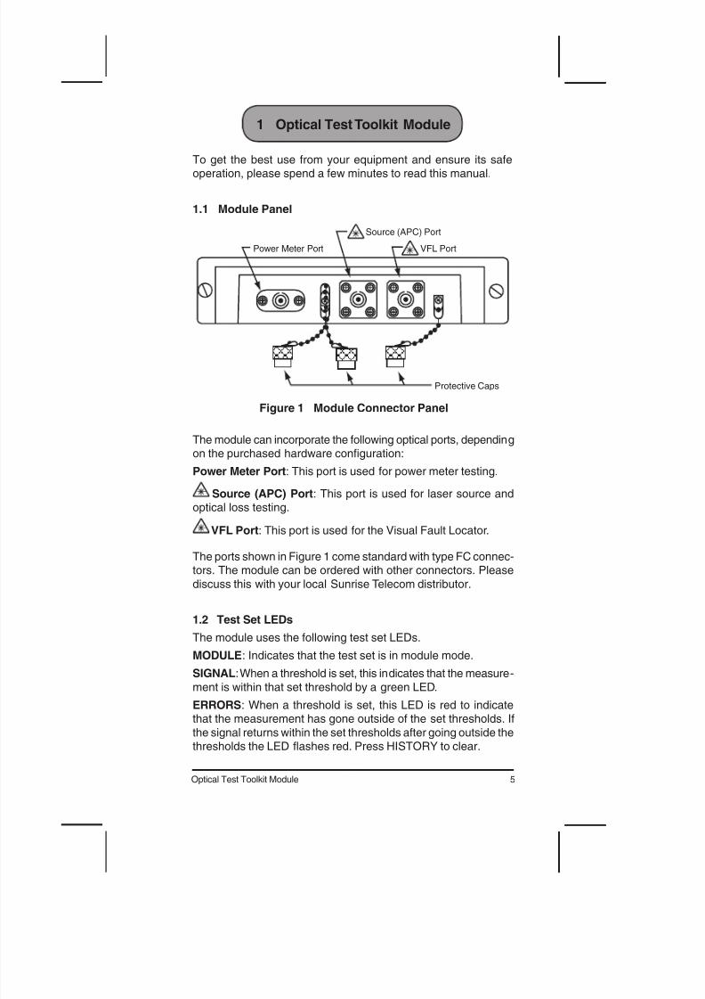
2.2 Optical Power Meter
11:50:45
OPTICAL POWER METER
MEASUREMENT MODE: BASICWAVELENGTH : 1550 nmMAX / MIN : ONTHRESHOLD : OFFUNIT : dB R REFERENCE: 0.00 dBm
MAX: -7.70 MIN: < -70
DARK C BASIC STORE
> <
>ET 000:01:00 ST 11:49:45<
-7.66 dB R
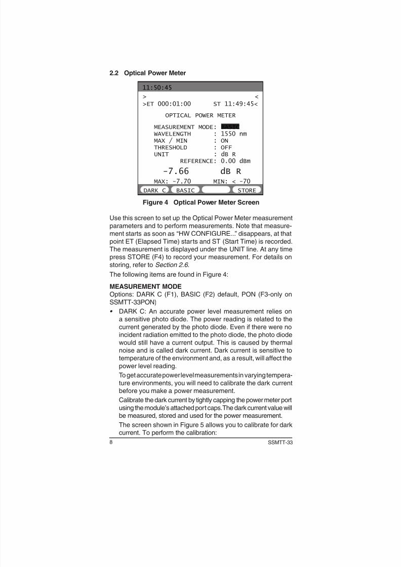
Figure 4 Optical Power Meter Screen
Use this screen to set up the Optical Power Meter measurement
parameters and to perform measurements. Note that measure-ment starts as soon as “HW CONFIGURE...” disappears, at that
point ET (Elapsed Time) starts and ST (Start Time) is recorded.The measurement is displayed under the UNIT line. At any timepress STORE (F4) to record your measurement. For details on
storing, refer to Section 2.6 .
The following items are found in Figure 4:
MEASUREMENT MODEOptions: DARK C (F1), BASIC (F2) default, PON (F3-only on
SSMTT-33PON)
• DARK C: An accurate power level measurement relies ona sensitive photo diode. The power reading is related to the
current generated by the photo diode. Even if there were noincident radiation emitted to the photo diode, the photo diode
would still have a current output. This is caused by thermalnoise and is called dark current. Dark current is sensitive totemperature of the environment and, as a result, will affect the
power level reading.
To get accurate power level measurements in varying tempera-
ture environments, you will need to calibrate the dark currentbefore you make a power measurement.
Calibrate the dark current by tightly capping the power meter port
using the module’s attached port caps. The dark current value willbe measured, stored and used for the power measurement.
The screen shown in Figure 5 allows you to calibrate for darkcurrent. To perform the calibration:
9Optical Test Toolkit Module
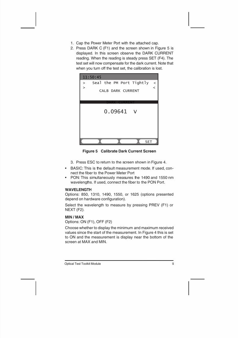
1. Cap the Power Meter Port with the attached cap.
2. Press DARK C (F1) and the screen shown in Figure 5 is
displayed. In this screen observe the DARK CURRENT
reading. When the reading is steady press SET (F4). The
test set will now compensate for the dark current. Note that
when you turn off the test set, the calibration is lost.
11:50:45
CALB DARK CURRENT
DARK CURRENT
SET
> Seal the PM Port Tightly <> <
0.09641 V
Figure 5 Calibrate Dark Current Screen
3. Press ESC to return to the screen shown in Figure 4.
• BASIC: This is the default measurement mode. If used, con-
nect the ber to the Power Meter Port• PON: This simultaneously measures the 1490 and 1550 nm
wavelengths. If used, connect the ber to the PON Port.
WAVELENGTH
Options: 850, 1310, 1490, 1550, or 1625 (options presenteddepend on hardware conguration).
Select the wavelength to measure by pressing PREV (F1) orNEXT (F2).
MIN / MAXOptions: ON (F1), OFF (F2)
Choose whether to display the minimum and maximum received
values since the start of the measurement. In Figure 4 this is setto ON and the measurement is display near the bottom of the
screen at MAX and MIN.
10 SSMTT-33
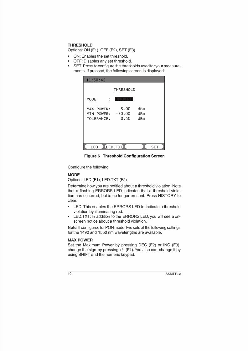
THRESHOLDOptions: ON (F1), OFF (F2), SET (F3)
• ON: Enables the set threshold.
• OFF: Disables any set threshold.• SET: Press to congure the thresholds used for your measure-
ments. If pressed, the following screen is displayed:
11:50:45
THRESHOLD
MODE : LED.TXT
MAX POWER: 5.00 dBm
MIN POWER: -50.00 dBm
TOLERANCE: 0.50 dBm
SETLED LED.TXT
Figure 6 Threshold Configuration Screen
Congure the following:
MODE
Options: LED (F1), LED.TXT (F2)
Determine how you are notied about a threshold violation. Notethat a flashing ERRORS LED indicates that a threshold viola-
tion has occurred, but is no longer present. Press HISTORY toclear.
• LED: This enables the ERRORS LED to indicate a thresholdviolation by illuminating red.
• LED.TXT: In addition to the ERRORS LED, you will see a on-screen notice about a threshold violation.
Note: If congured for PON mode, two sets of the following settings
for the 1490 and 1550 nm wavelengths are available.
MAX POWER
Set the Maximum Power by pressing DEC (F2) or INC (F3),change the sign by pressing +/- (F1). You also can change it byusing SHIFT and the numeric keypad.
11Optical Test Toolkit Module
MIN POWERSet the Minimum Power by pressing DEC (F2) or INC (F3), change
the sign by pressing +/- (F1). You also can change it by usingSHIFT and the numeric keypad.
TOLERANCESet the tolerance for the MIN and MAX Power threshold settings
in dBm. If the received power is in violation of a MAX/MIN setting,but within your tolerance setting, the test set will display MARG,but the ERRORS LED will be off.
Change TOLERANCE by pushing and holding either (decrement)
DEC (F2) or (increment) INC (F3). You also can change it by usingSHIFT and the numeric keypad.
When done, press SET (F4) to return to the Optical Power MeterScreen shown in Figure 4.
UNIT
Options: dBm (F1), uW (F2), dB R (F3)
Select the unit of measurement.
• dBm: This is an absolute decibel power measurement.• uW: This measures power in microwatts.• dB R: This is a relative decibel power measurement; power is
measured with a reference to the set reference point. If used,an additional setting is displayed, REF. You will then need to
enter a reference for your measurement. Note that the currentmeasured power level can be set as a reference by pressing
SET (F1) when the REFERENCE line is selected.
When done, press ESC to return to the module main menu
screen.
12 SSMTT-33
2.3 Insertion Loss
This menu screen contains the following items:
• SET SOURCE• REFERENCING
• LOSS MEASUREMENT
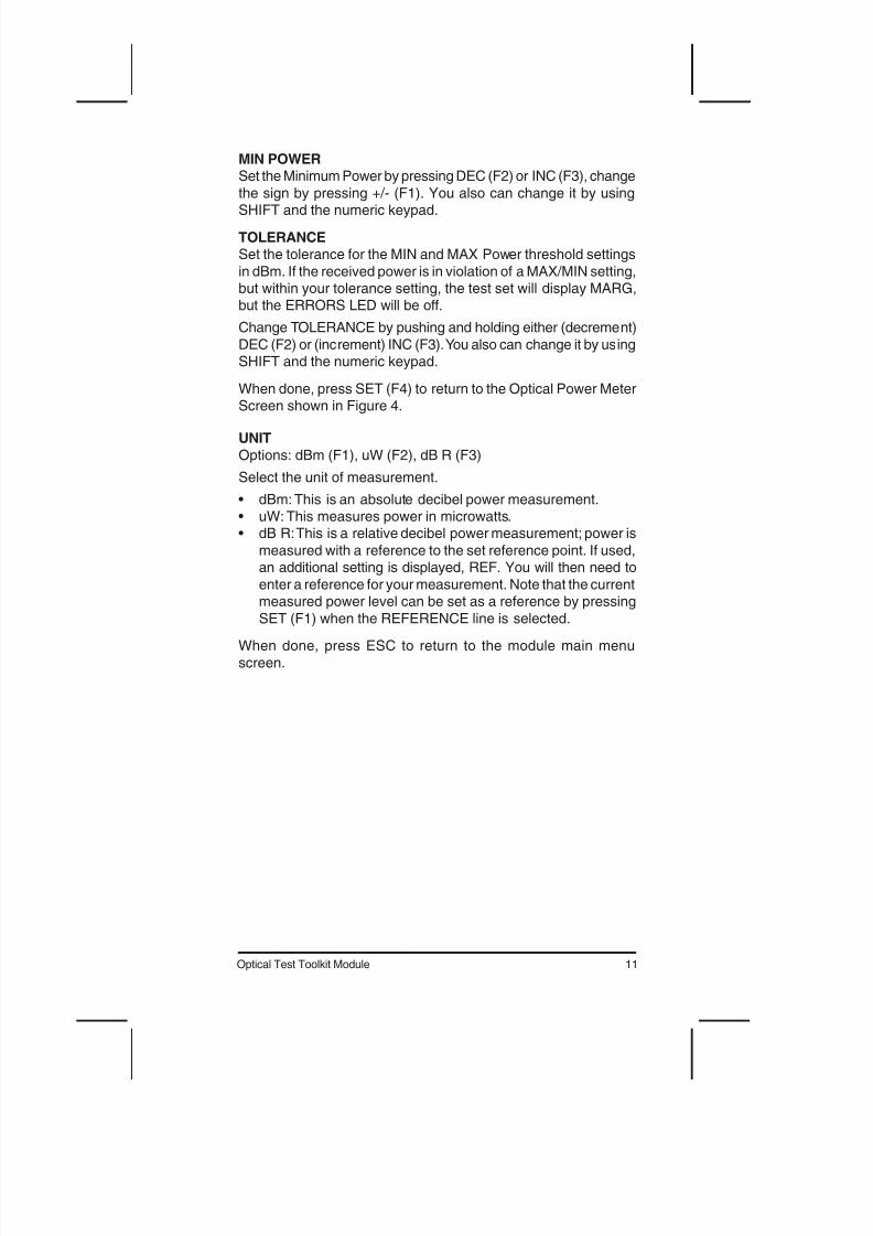
2.3.1 Set Source
Set the transmit level of the source for Referencing and/or LossMeasurement in the following screen:
11:50:45
SET SOURCE
INC
> <
>ET 000:00:03 ST 11:50:42<
TX LEVEL : -2.50 dBm
DEFAULT DEC START
Figure 7 Set Source Screen
TX LEVELOptions: SSMTT-33LTS; -2.50 through -10.00, default -2.50. -
33LTSP; -5.50 through -10.00, default -5.50
Change the transmit level by pushing and holding either (decre-
ment) DEC (F2) or (increment) INC (F4). You may also pressDEFAULT (F1). You also can enter the TX LEVEL by using SHIFTand the numeric keypad.
You may press START (F3) in this screen to enter the optical
insertion loss measurement screen. Note that doing so skips theReferencing step.
13Optical Test Toolkit Module
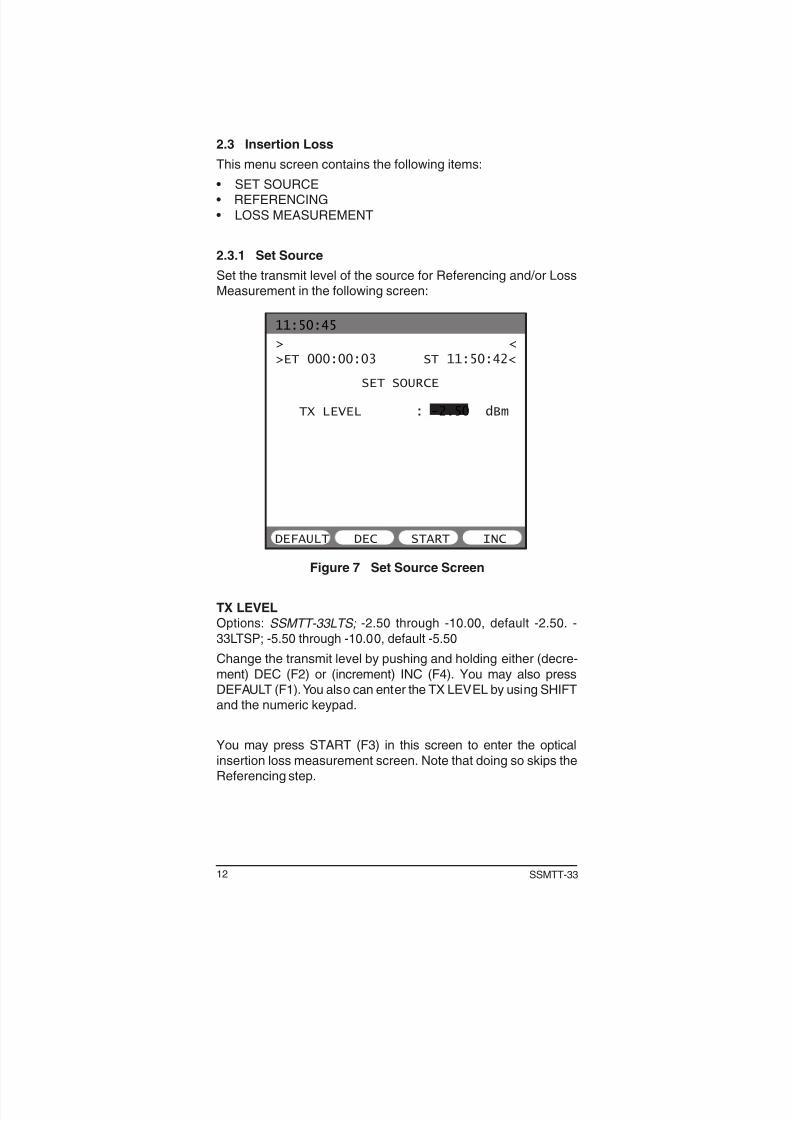
2.3.2 Referencing
This procedure allows the test set to account for the loss of the testsetup, i.e., the patch cable used to connect to the circuit. It should
be performed for both test sets used in the Insertion Loss test.
1. Using the patch cord you use for testing, connect the Source(APC) port to the Power Meter port as shown in Figure 8.
Power Meter Port
Source (APC) Port
Optic cable used to connect to circuit.
Figure 8 Referencing Connections
2. Select INSERTION LOSS > REFERENCING and refer toFigure 9.
11:50:45
REFERENCING
SET
> <
>ET 000:00:03 ST 11:50:42<
START
POWER: -3.94 -3.98
1310 1550
CONNECT POWER METER PORT
TO LASER SOURCE PORT
Note: A thirdwavelength (1490nm) column maybe displayed in thisscreen dependingon your purchasedoptions.
Figure 9 Insertion Loss Referencing Screen
14 SSMTT-33
3. Press START (F4) to begin transmitting the source and mea-suring power.
4. Press SET (F3) to save the reference result and go to thescreen shown in Figure 11. Refer to Section 2.3.3 for details.
5. Disconnect the end of the patch cable that is connected tothe Power Meter Port and connect it to the Fiber Under Test
(FUT). Do so on both test sets.
• Note: If the test set is turned off, the reference result is lost.
The screen shown in Figure 9 contains the following:
ST: Start Time since pressing START (F4).
ET: Elapsed Time since pressing START (F4). Note that both
times are in HHH:MM:SS format.
POWER: Reports the measured power level for each availablewavelength.
15Optical Test Toolkit Module
2.3.3 Loss Measurement
This measurement requires two test sets connected together inInsertion Loss mode as in Figure 10; start the test at either end.
Source (APC) Port
Source (APC) Port
(A)
Near end
(B)
Far end
Patch Cable
Patch Cable
Connection
Points
Fiber Under Test
Figure 10 Insertion Loss Connection
>CONNECTED <
>ET 000:00:59 ST 11:49:44<
11:50:45
INSERTION LOSS
STOP STORE
A2B Tx: -3.91 -4.00
B Rx: -3.83 -4.35
LOSS: -0.08 -0.32
B2A Tx: -5.50 -5.50
A Rx: -5.59 -5.73
LOSS: 0.10 0.23
* 1310 1550
UNIT : dBm
dBm uW
Note: A thirdwavelength (1490nm) column maybe displayed in thisscreen dependingon your purchasedoptions.
Figure 11 Insertion Loss Measurement Screen
This screen contains the following:
UNIT
Options: dBm (F1), uW (F2)
• Select your measure mode dBm or uW.
16 SSMTT-33
At any time press F3 to start measuring, press again to stop.
During the measurement you may store the measurement by
pressing F4. Refer to Section 2.6 for details.
After pressing START (F3) the following information is presentedfor different wavelengths. Press STOP (F3) to halt measuring.
A2B Tx: Near-to-far transmit power level.
B Rx: Power level received from the far end.
LOSS: Power loss from near to far end.
B2A Tx: Far-to-near transmit power level.
A Rx: Measured power from the near end.
LOSS: Power loss from far to near end.
Note: A = near-end, B = far-end
17Optical Test Toolkit Module
2.4 Optical Return Loss
The Optical Return Loss menu screen contains the following
items:
• SET SOURCE• REFERENCING• LOSS MEASUREMENT
2.4.1 Set Source
Refer to Section 2.3.1.
2.4.2 Referencing
Refer to Section 2.3.2 .
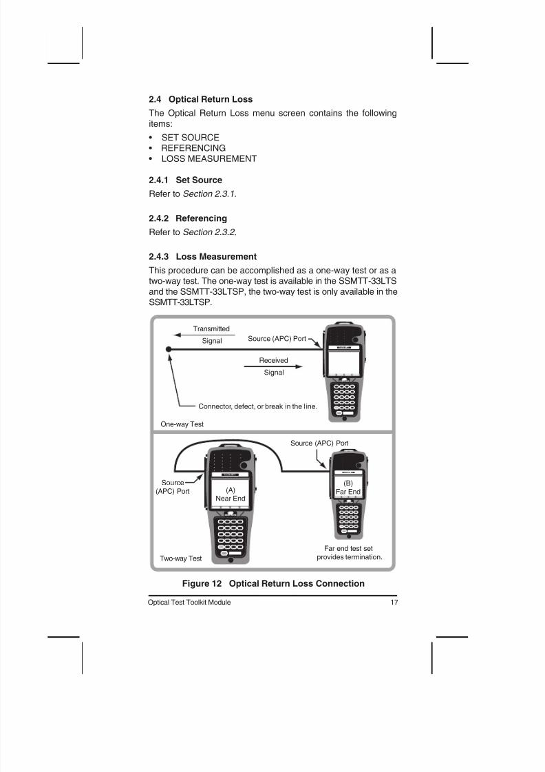
2.4.3 Loss Measurement
This procedure can be accomplished as a one-way test or as atwo-way test. The one-way test is available in the SSMTT-33LTS
and the SSMTT-33LTSP, the two-way test is only available in theSSMTT-33LTSP.
Transmitted
Signal Source (APC) Port
Connector, defect, or break in the l ine.
Received
Signal
One-way Test
Two-way Test
(A)Near End
(B)Far End
Far end test setprovides termination.
Source (APC) Port
Source(APC) Port
Figure 12 Optical Return Loss Connection
18 SSMTT-33
RefZero STOPRst Ref MORE
11:50:45
OPTICAL RETURN LOSS
dBm
> Fiber should be terminated. <
>ET 000:00:03 ST 11:50:42<
STOP
POWER : -19.36 -19.35
ORL : 15.27 15.54
1310 1550
uW MORE
MEASUREMENT MODE:1-WAY
UNIT : dBm
Laser
STOPSTORE MORE
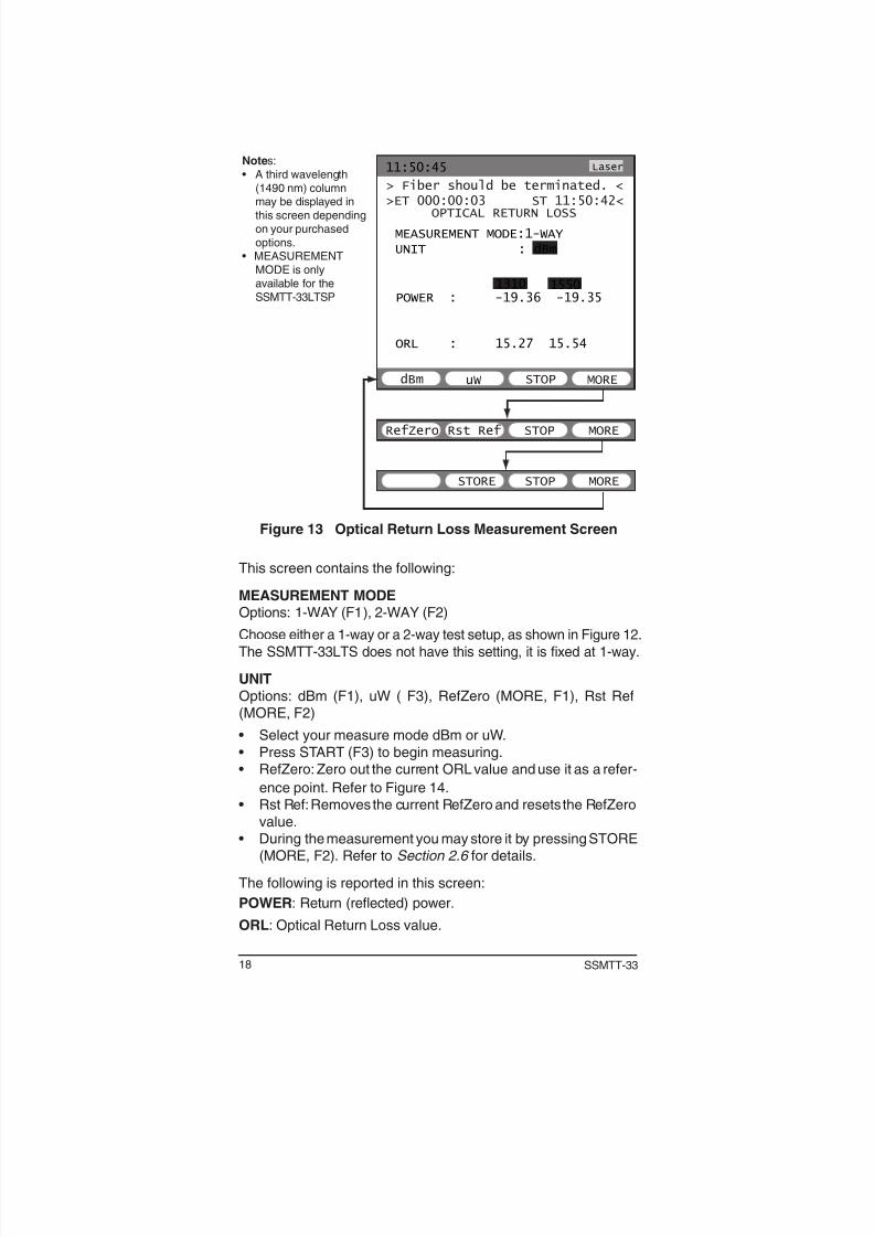
Notes:• A third wavelength
(1490 nm) columnmay be displayed inthis screen dependingon your purchasedoptions.
• MEASUREMENTMODE is onlyavailable for theSSMTT-33LTSP
Figure 13 Optical Return Loss Measurement Screen
This screen contains the following:
MEASUREMENT MODEOptions: 1-WAY (F1), 2-WAY (F2)
Choose either a 1-way or a 2-way test setup, as shown in Figure 12.
The SSMTT-33LTS does not have this setting, it is xed at 1-way.
• Press START (F3) to begin measuring.• RefZero: Zero out the current ORL value and use it as a refer-
ence point. Refer to Figure 14.• Rst Ref: Removes the current RefZero and resets the RefZero
value.• During the measurement you may store it by pressing STORE
(MORE, F2). Refer to Section 2.6 for details.
The following is reported in this screen:
POWER: Return (reected) power.
ORL: Optical Return Loss value.
19Optical Test Toolkit Module
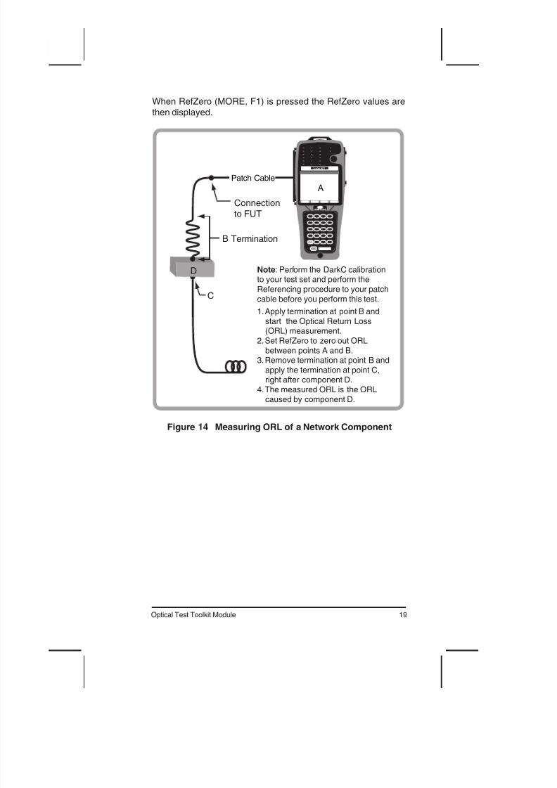
When RefZero (MORE, F1) is pressed the RefZero values are
then displayed.
Note: Perform the DarkC calibrationto your test set and perform the
Referencing procedure to your patch
cable before you perform this test.
1. Apply termination at point B and
start the Optical Return Loss(ORL) measurement.
2. Set RefZero to zero out ORL
between points A and B.3. Remove termination at point B and
apply the termination at point C,right after component D.
4. The measured ORL is the ORL
caused by component D.
B Termination
C
D
A
Connection
to FUT
Patch Cable
Figure 14 Measuring ORL of a Network Component
20 SSMTT-33
2.5 Visual Fault Locator
The Visual Fault Locator works by transmitting a visible light signalat 650 nm. The signal can be set to Continuous Wave (CW) mode
or modulated at 2 Hz. At a fault, visible light appears. It works bestover distances of less than 1 km but can have a range of up to 5
km. Use the following screen to set up the light signal.
11:50:45
VISUAL FAULT LOCATOR
2 Hz STOP
CONTINUOUS
WAVE
MODULATION FREQ
CW
VFL
Figure 15 Visual Fault Location Screen
The screen contains one item to configure, it is:
MODULATION FREQ
Option: 2 Hz (F1), CW (F2)
Select either a 2 Hz (on/off pulse) or a Continuous Wave (alwayson) signal.
When ready press START (F3) to turn on the light source. Press
STOP (F3) to turn off the light source. VFL indicates that the Vis-ible Frequency Laser is active.
21Optical Test Toolkit Module
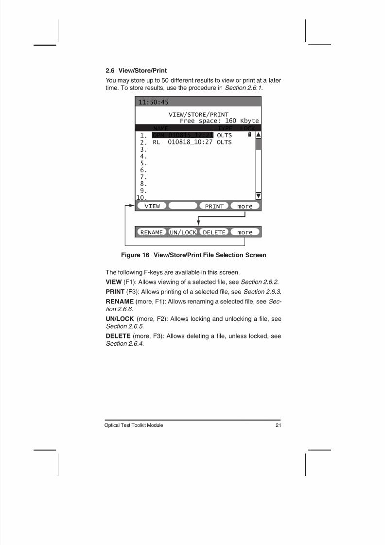
2.6 View/Store/Print
You may store up to 50 different results to view or print at a latertime. To store results, use the procedure in Section 2.6.1.
RENAME DELETE moreUN/LOCK
11:50:45
VIEW/STORE/PRINT
VIEW PRINT more
Free space: 160 KbyteNAME TYPE LOCK
1.2.3.4.5.6.7.8.9.10.
OPM 010815_12:21 OLTSRL 010818_10:27 OLTS
Figure 16 View/Store/Print File Selection Screen
The following F-keys are available in this screen.
VIEW (F1): Allows viewing of a selected le, see Section 2.6.2 .
PRINT (F3): Allows printing of a selected le, see Section 2.6.3 .
RENAME (more, F1): Allows renaming a selected le, see Sec-
tion 2.6.6.
UN/LOCK (more, F2): Allows locking and unlocking a le, seeSection 2.6.5 .
DELETE (more, F3): Allows deleting a le, unless locked, see
Section 2.6.4 .
22 SSMTT-33
2.6.1 Saving a Test
1. From any screen with a STORE F-key, press it and the recordis stored. The filename is based on the type of test, date, and
time of day.
2.6.2 Viewing a Stored Test
1. From the OPTICAL TEST TOOLKIT main menu, select VIEW/ STORE/PRINT.
2. Select the desired le with the keypad up/down cursor keys.3. Press VIEW (F1) and the stored result will appear.
4. Use the keypad up/down cursor keys to scroll through theavailable screens.
5. When nished, press ESC to return to the VIEW/STORE/PRINT screen.
2.6.3 Printing a Stored Test
1. Connect a SunSet printer to the serial port of the test set.
• For other types of printers or for more information, refer to theStoring and Printing chapter in the test set user’s manual.
2. From OPTICAL TEST TOOLKIT main menu, select VIEW/
STORE/PRINT.3. Select the desired le with the keypad up/down cursor keys.4. Press PRINT (F3) and the le will begin printing.
5. When nished, press ESC to return to the VIEW/STORE/PRINT screen.
2.6.4 Deleting a Stored Test
1. From the OPTICAL TEST TOOLKIT main menu, select VIEW/ STORE/PRINT.
2. Select the desired le with the keypad up/down cursor keys.
3. Press DELETE (more, F3) and the file is deleted (if it is un-locked).
2.6.5 Locking & Unlocking a Stored Test
1. From the OPTICAL TEST TOOLKIT main menu, select VIEW/ STORE/PRINT.
2. Select the desired le with the keypad up/down cursor keys.3. Press UN/LOCK (more, F2) and the le is locked or unlocked
as indicated to the right of the file name. Refer to the lock icon
shown in Figure 16.
23Optical Test Toolkit Module
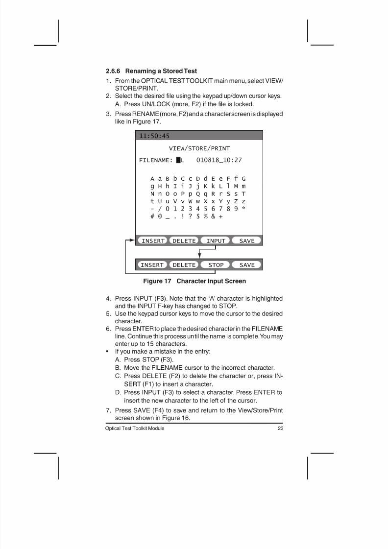
2.6.6 Renaming a Stored Test
1. From the OPTICAL TEST TOOLKIT main menu, select VIEW/ STORE/PRINT.
2. Select the desired le using the keypad up/down cursor keys.
A. Press UN/LOCK (more, F2) if the le is locked.
3. Press RENAME (more, F2) and a character screen is displayed
like in Figure 17.
11:50:45
VIEW/STORE/PRINT
INSERT INPUT SAVE
FILENAME: RL 010818_10:27
DELETE
INSERT STOP SAVEDELETE
A a B b C c D d E e F f Gg H h I i J j K k L l M mN n O o P p Q q R r S s Tt U u V v W w X x Y y Z z- / 0 1 2 3 4 5 6 7 8 9 *# @ _ . ! ? $ % & +
Figure 17 Character Input Screen
4. Press INPUT (F3). Note that the ‘A’ character is highlightedand the INPUT F-key has changed to STOP.
5. Use the keypad cursor keys to move the cursor to the desiredcharacter.
6. Press ENTER to place the desired character in the FILENAMEline. Continue this process until the name is complete. You mayenter up to 15 characters.
• If you make a mistake in the entry:
A. Press STOP (F3).
B. Move the FILENAME cursor to the incorrect character.
C. Press DELETE (F2) to delete the character or, press IN-
SERT (F1) to insert a character.
D. Press INPUT (F3) to select a character. Press ENTER to
insert the new character to the left of the cursor.
7. Press SAVE (F4) to save and return to the View/Store/Printscreen shown in Figure 16.
24 SSMTT-33
3 Applications
The insertion loss and optical return loss features of this moduleare handy economical tools for analyzing the physical plant equip-
ment and systems during design, installation, maintenance, andtroubleshooting phases of optical ber networks.
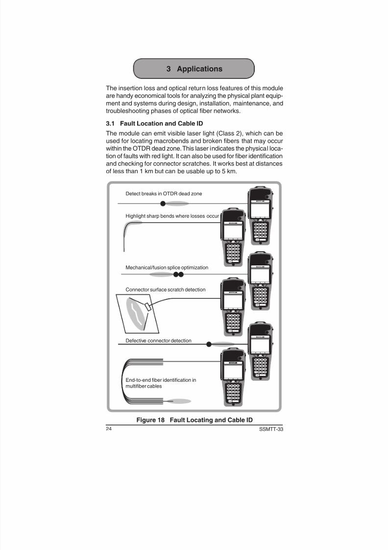
3.1 Fault Location and Cable ID
The module can emit visible laser light (Class 2), which can beused for locating macrobends and broken fibers that may occurwithin the OTDR dead zone. This laser indicates the physical loca-
tion of faults with red light. It can also be used for ber identicationand checking for connector scratches. It works best at distances
The module can be used as a light source in ber network ser-vice verication. Supports switchable wavelengths of 850/1310,
1310/1550, and 1550/1625 nm.
3.3 Loss Test (Power Meter + Laser Source)
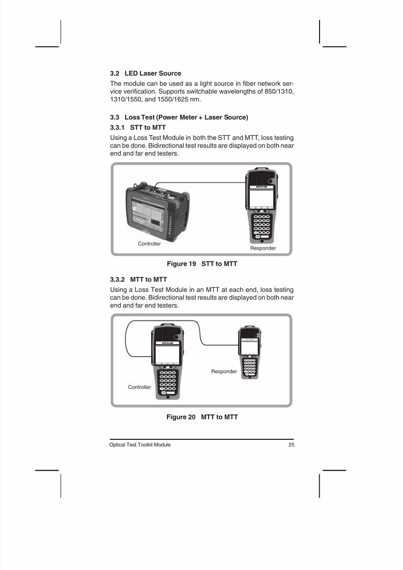
3.3.1 STT to MTT
Using a Loss Test Module in both the STT and MTT, loss testing
can be done. Bidirectional test results are displayed on both nearend and far end testers.
ResponderController
Figure 19 STT to MTT
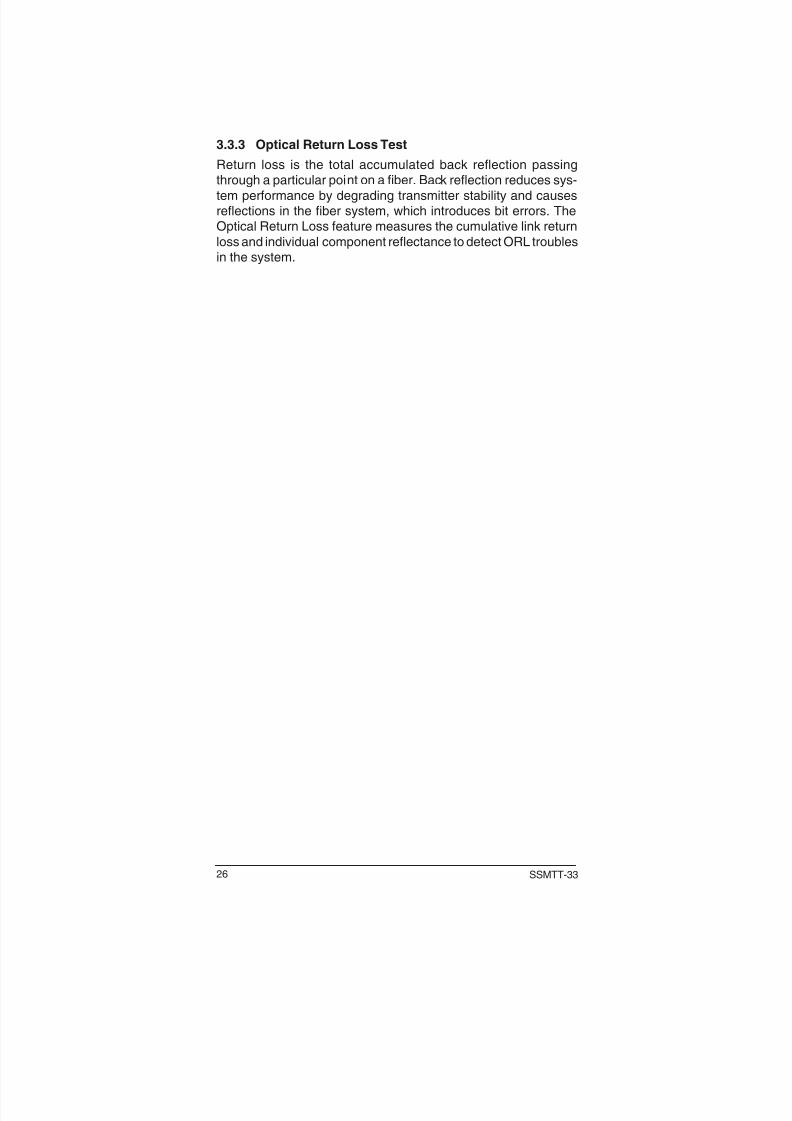
3.3.2 MTT to MTT
Using a Loss Test Module in an MTT at each end, loss testingcan be done. Bidirectional test results are displayed on both near
end and far end testers.
Responder
Controller
Figure 20 MTT to MTT
26 SSMTT-33
3.3.3 Optical Return Loss Test
Return loss is the total accumulated back reflection passingthrough a particular point on a fiber. Back reflection reduces sys-
tem performance by degrading transmitter stability and causesreections in the ber system, which introduces bit errors. TheOptical Return Loss feature measures the cumulative link return
loss and individual component reflectance to detect ORL troublesin the system.
27Optical Test Toolkit Module
4 Reference
4.1 Handling of Optical Fiber
Proper handling of optical fiber cables, connectors, and equipment
is important in obtaining accurate measurements and prevent-ing potential transmission problems. This section reviews proper
handling procedures for optical fiber.
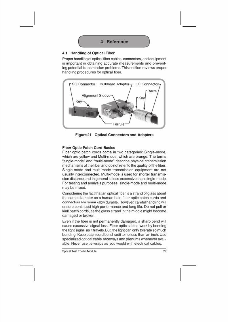
SC Connector Bulkhead Adaptor FC Connector
Key
Alignment SleeveKey
Barrel
Ferrule
Figure 21 Optical Connectors and Adapters
Fiber Optic Patch Cord BasicsFiber optic patch cords come in two categories: Single-mode,
which are yellow and Multi-mode, which are orange. The terms“single-mode” and “multi-mode” describe physical transmission
mechanisms of the fiber and do not refer to the quality of the fiber.Single-mode and multi-mode transmission equipment are notusually interconnected. Multi-mode is used for shorter transmis-
sion distance and in general is less expensive than single-mode.For testing and analysis purposes, single-mode and multi-mode
may be mixed.
Considering the fact that an optical fiber is a strand of glass aboutthe same diameter as a human hair, fiber optic patch cords and
connectors are remarkably durable. However, careful handling willensure continued high performance and long life. Do not pull orkink patch cords, as the glass strand in the middle might become
damaged or broken.
Even if the ber is not permanently damaged, a sharp bend willcause excessive signal loss. Fiber optic cables work by bending
the light signal as it travels. But, the light can only tolerate so muchbending. Keep patch cord bend radii to no less than an inch. Use
specialized optical cable raceways and plenums whenever avail-able. Never use tie wraps as you would with electrical cables.
28 SSMTT-33
4.2 Fiber Optic Connectors
Alignment Sleeve Ferrule of Connector B
Ferrule of Connector A Alignment Sleeve
FiberFiber End Faces Touch
Figure 22 Cross-Sectional View of Connectors
In the electrical world, female connectors are mated to maleconnectors. In the optical world, the connection mechanism is
altogether different. Fiber optic connector systems are designedto align two ber ends so that the light signal will pass between
them; imagine trying to align two hairs end to end. Modern beroptic connector systems solve this nearly impossible task. There
are several types of optical connectors in use today. Figure 21shows the two most popular, SC and FC. In this example, an SC toFC bulkhead adapter is used to connect the two bers together.
In Figure 22, a schematic of the connector cross section demon-
strates the details of the connection mechanism. Ceramic ferruleson the connector ends are kept in alignment by a sleeve in the
connector bulkhead adapter. The fiber itself is mounted in theexact center of the ferrule. When the ferrules are aligned by the
sleeve, so are the fibers. Springs in the connector bodies provideconsistent pressure so that the two connector end faces are as-sured to be in contact with each other. Since all tolerances must
be kept extremely tight, it is amazing that the typical connectorsignal loss is usually less than a couple tenths of a dB.
When using optical connectors, insert or remove the ferrule
straight into the sleeve. Try to minimize wiggling the connector asthis may loosen the tight t between the ferrule and sleeve. For
SC connectors, orient the prominent key on the connector body(Figure 21) with the slot in the bulkhead adapter. Push the con-nector until it clicks. To remove, pinch the connector body between
your thumb and finger, and gently pull straight out.
FC connectors require more care. Find the small key and orient itwith the equally small slot in the threaded section of the bulkhead
adapter. Even in Figure 21, this key is not very visible. Thread theouter barrel only lightly finger tight. Never use pliers! Over tight-
ening the barrel will not improve signal transmission and could
29Optical Test Toolkit Module
cause permanent damage. To remove, unthread the barrel, and
gently pull straight out.
Most problems with FC connectors are due to key misalignment.This is difcult to detect since even when the key is misaligned, thebarrel can be threaded, which then hides the misaligned key. A hint
is when the barrel only catches the rst one or two threads. Also, theconnector will not be completely seated in the bulkhead adapter.
4.3 Cleaning Optical Fiber
Fiber optic connectors must be kept clean to ensure long life and
to minimize transmission loss at the connection point. When not inuse, always replace dust covers and caps to prevent deposits andlms from airborne particles. A single dust particle caught between
two connectors will cause signicant signal loss. Even worse, dustparticles can scratch the polished fiber end, resulting in permanent
damage. Do not touch the connector end or the ferrules, sincethis will leave an oily deposit from your ngers. Likewise, do not
allow uncapped connectors to drop on the oor.
Should a fiber connector become dir ty or exhibit high loss, care-fully clean the entire ferrule and end face. Special lint-free padsshould be used with isopropyl alcohol. Even though not very ac-
cessible, the end face in a bulkhead adapter on test equipmentcan be cleaned by using a special lint-free swab, again with
isopropyl alcohol. In extreme cases, test equipment may requiremore thorough cleaning at the factory.
Cotton, paper, or solvents should never be used for cleaning since
they may leave behind particles or residues. Use a fiber opticcleaning kit especially made for cleaning optical connectors, andfollow the directions. Some kits come with canned air to blow any
dust out of the bulkhead adapters. Be cautious, as canned air cando more harm than good if not used properly. Again, follow the
directions that come with the kit.
4.4 Eye Safety
It is good safety practice to never look directly into the end of aber or bulkhead adapter. You may be working with equipment thattransmits at high power and are not eye-safe. For added safety, turn
the laser off when not in use. In any case, the wavelengths used intelecommunications are not visible, so the presence of an optical
signal cannot be determined by looking into the fiber end.
Summary
Take care of your ber. Always replace dust covers. Keep optical con-nectors clean and make a practice of not looking into fiber ends.
30 SSMTT-33
4.5 Express Limited Warranty
This Sunrise Telecom product is warranted against defects inmaterials and workmanship during its warranty period. The war-
ranty period for this product is contained in the warranty page onhttp://www.sunrisetelecom.com.
Sunrise Telecom agrees to repair or replace any assembly or
component found to be defective under normal use during thisperiod. The obligation under this warranty is limited solely to re-pairing or replacing the product that proves to be defective within
the scope of the warranty when returned to the factory. This war -ranty does not apply under certain conditions, as set forth on the
warranty page on http://www.sunrisetelecom.com.
Please refer to the website for specic details.THIS IS A LIMITED WARRANTY AND THE ONLY WARRANTY
MADE BY SUNRISE TELECOM. SUNRISE TELECOM MAKESNO OTHER WARRANTY, REPR SENTATION OR CONDITION,EXPRESS OR IMPLIED, AND EXPRESSLY DISCLAIMS THE
IMPLIED WARRANTIES OF MERCHANTABILITY, FITNESSFOR A PARTICULAR PURPOSE AND NON-INFRINGEMENT
OF THIRD PARTY RIGHTS.
31Optical Test Toolkit Module
Index
A
ApplicationsLED/Laser Source; 25
Loss Test (Power Meter + Laser Source); 25Optical Return Loss Test; 26
Visual Fault Locator; 24
C
Cautions; 2
F
Figures01 Module Connector Panel; 502 Menu Tree for the SSMTT-33LTS and -33LTSP; 6
03 Light Source Screen; 704 Optical Power Meter Screen; 8
05 Calibrate Dark Current Screen; 906 Threshold Configuration Screen; 10
07 Set Source Screen; 1208 Referencing Connections; 1309 Insertion Loss Referencing Screen; 13
10 Insertion Loss Connection; 1511 Insertion Loss Screen; 15
12 Optical Return Loss Connection; 1713 Optical Return Loss Measurement Screen; 18
14 Measuring ORL of a Network Component; 1915 Visual Fault Location Screens; 2016 View/Store/Print File Selection Screen; 21
17 Character Input Screen; 2318 Fault Locating and Cable ID; 24
19 STT to MTT; 2520 MTT to MTT; 25
21 Optical Connectors and Adapters; 2722 Cross-Sectional View of Connectors; 28
H
Handling of Optical Fiber; 27
I
Insertion Loss Measurement Screen
A2B Tx; 16A Rx; 16B2A Tx; 16
B Rx; 16LOSS; 16
32 SSMTT-33
L
LED/Laser Source ScreenAUTO SHUT-OFF; 7
MODULATION FREQ; 7TX LEVEL; 7
WAVELENGTH; 7Loss Measurement Screen
MEASUREMENT MODE1-WAY; 182-WAY; 18
ORL; 18POWER; 18
UNIT; 18
M
Module Panel
PortsPower Meter; 5
Source (APC); 5type FC; 5Visual Fault Locator; 5
O
Optical Power Meter ScreenBASIC; 9
DARK C; 8MEASUREMENT MODE; 8
MIN / MAX; 9THRESHOLD; 10
UNIT; 11WAVELENGTH; 9
R
Referencing; 13
S
Set Source ScreenTX LEVEL; 12
T
Test Set LEDsERRORS; 5
MODULE; 5SIGNAL; 5
Threshold Configuration ScreenMAX POWER; 10
MIN POWER; 11
33Optical Test Toolkit Module
MODE
LED; 10LED.TXT; 10
TOLERANCE; 11
V
View/Store/Print ScreenDeleting a Stored Test; 22
Locking & Unlocking a Stored Test; 22Printing a Stored Test; 22


![スツール総合カタログ Stool Series...U-Stool [DR-US001 ] 初高:430mm ストローク:165mm 本体昇降機構:ガスシリンダー式 手動操作 製品質量:8kg](https://static.documents.pub/doc/80x56/60bb0850d1438e29e91de822/fffcf-stool-series-u-stool-dr-us001-ei430mm.jpg)


