DIDACTIC MANUAL FAMILY: Wall-hung boilers GROUP: Instantaneous type and forced draught heating only MODELS: Itaca VERSIONS: For indoor and outdoor installation PART NO.: AST 14 C 255/00 ______________________________________________ 1st Edition, January 2013 ENGLISH
Transcript
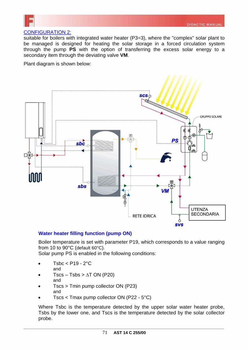
DIDACTIC MANUAL
FAMILY: Wall-hung boilers
GROUP: Instantaneous type and forced draught heating
only
MODELS: Itaca
VERSIONS: For indoorand outdoor installation
PART NO.: AST 14 C 255/00
______________________________________________1st Edition, January 2013
EN
GL
ISH
________________________________________________________________________________ 2 AST 14 C 255/00
ITACA CTFS 24 - 28 - 32: atmospheric boiler for indoor installation, combined instantaneous, with production of domestic hot water + heating, sealed chamber, forced draught, mono-thermal with plate exchanger;
ITACA CTFS 24 - 28 - 32 for outdoor installation: atmospheric boiler for indoor installation, combined instantaneous, with production of domestic hot water + heating, sealed chamber, forced draught, mono-thermal with plate exchanger;
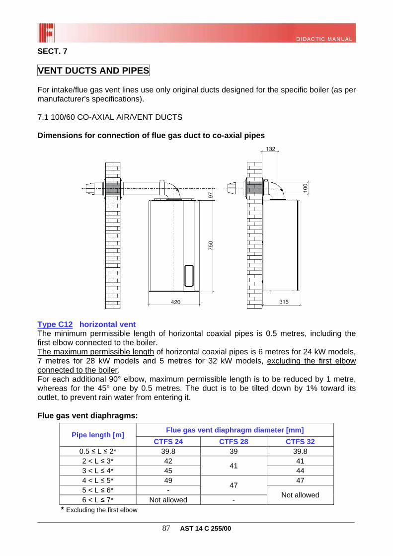
1.2 OVERALL DIMENSIONS Height H = 750 mm
Width L = 420 mm
Depth D = 315 mm
________________________________________________________________________________ 5 AST 14 C 255/00
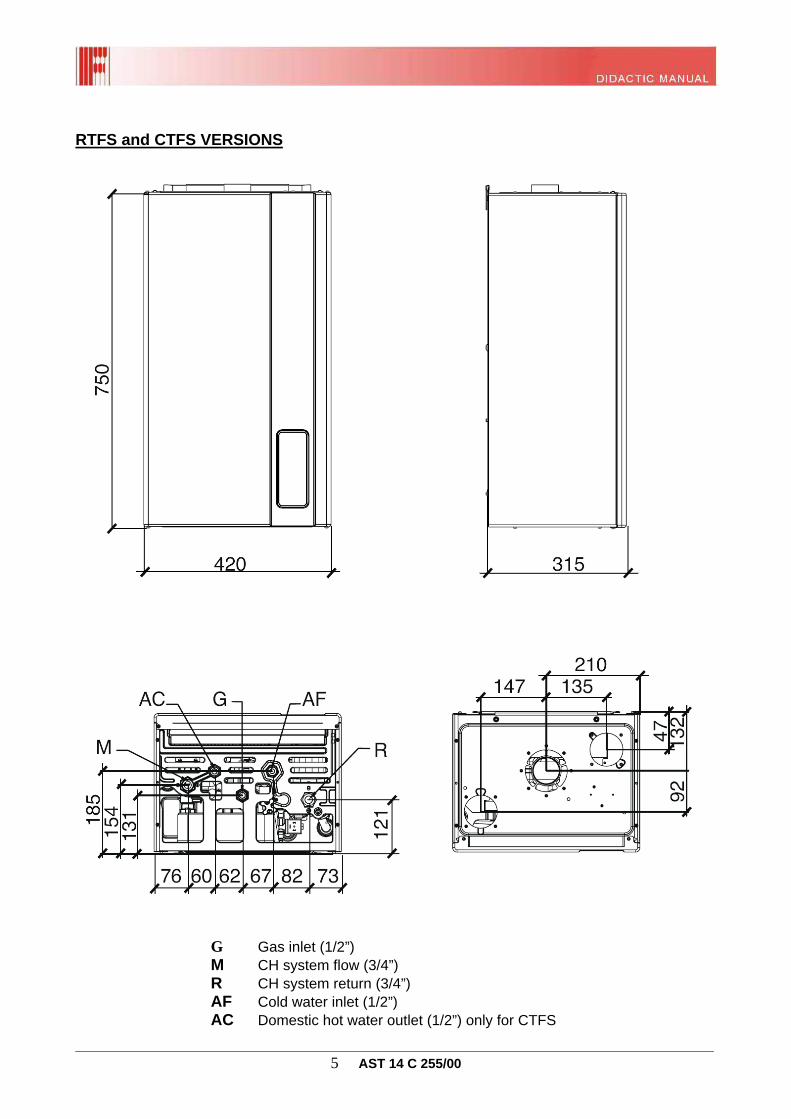
RTFS and CTFS VERSIONS
G Gas inlet (1/2”) M CH system flow (3/4”) R CH system return (3/4”) AF Cold water inlet (1/2”) AC Domestic hot water outlet (1/2”) only for CTFS
________________________________________________________________________________ 6 AST 14 C 255/00
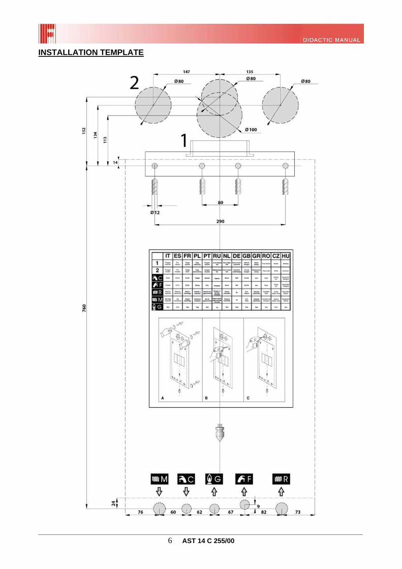
INSTALLATION TEMPLATE
________________________________________________________________________________ 7 AST 14 C 255/00
1.3 TECHNICAL SPECIFICATIONS General Characteristics
RTFS CTFS
24 kW 28 kW 24 kW 28 kW 32 kW
Operating parameters Equipment category II2H3+
Burner nozzles no. 11 13 11 13 15
CH circuit max. and min. pressure bar 3 - 0.5
DHW circuit max. and min. pressure (KC) bar - 6 - 0.5
________________________________________________________________________________ 10 AST 14 C 255/00
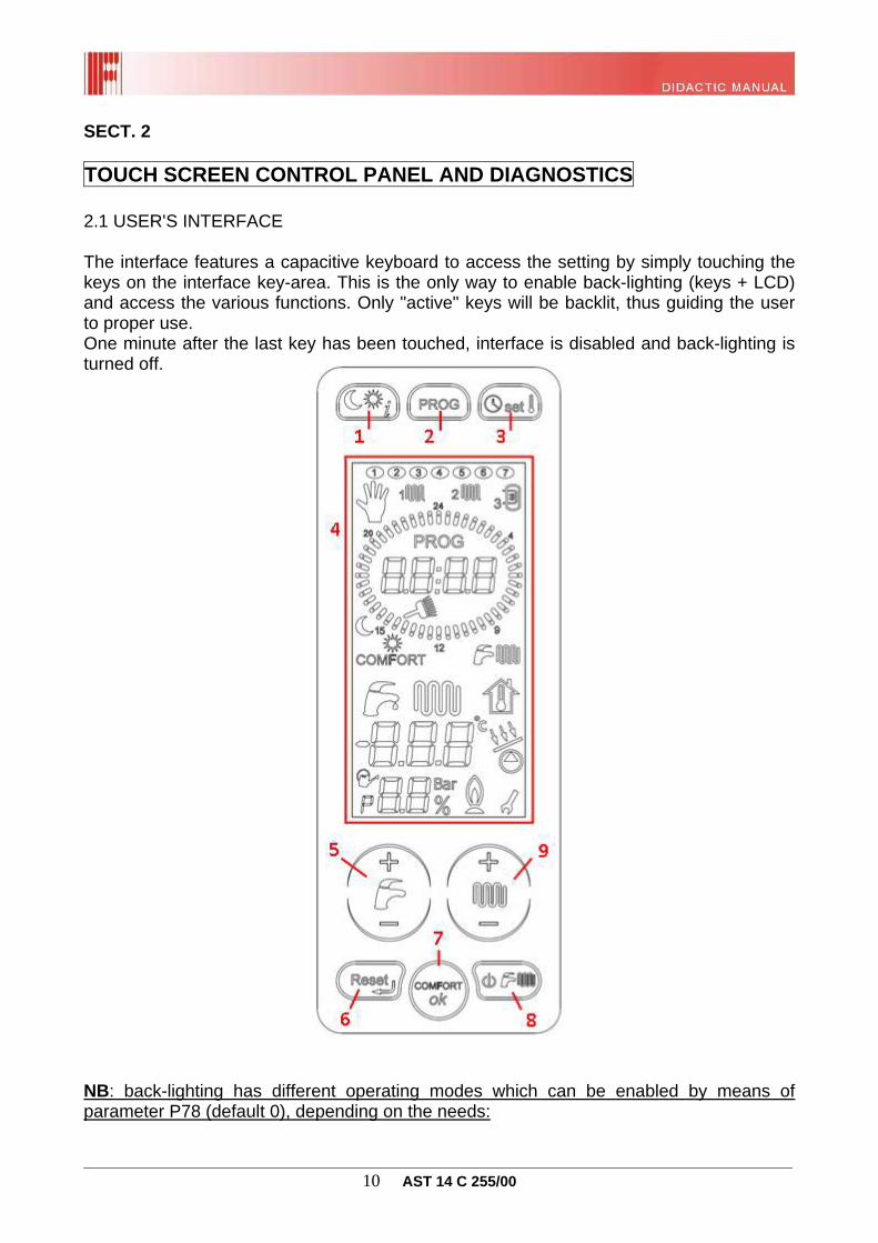
SECT. 2 TOUCH SCREEN CONTROL PANEL AND DIAGNOSTICS 2.1 USER'S INTERFACE The interface features a capacitive keyboard to access the setting by simply touching the keys on the interface key-area. This is the only way to enable back-lighting (keys + LCD) and access the various functions. Only "active" keys will be backlit, thus guiding the user to proper use. One minute after the last key has been touched, interface is disabled and back-lighting is turned off.
NB: back-lighting has different operating modes which can be enabled by means of parameter P78 (default 0), depending on the needs:
________________________________________________________________________________ 11 AST 14 C 255/00
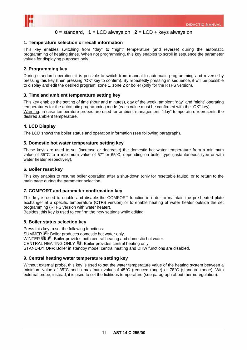
0 = standard, 1 = LCD always on 2 = LCD + keys always on 1. Temperature selection or recall information
This key enables switching from “day” to “night” temperature (and reverse) during the automatic programming of heating times. When not programming, this key enables to scroll in sequence the parameter values for displaying purposes only. 2. Programming key
During standard operation, it is possible to switch from manual to automatic programming and reverse by pressing this key (then pressing “OK” key to confirm). By repeatedly pressing in sequence, it will be possible to display and edit the desired program: zone 1, zone 2 or boiler (only for the RTFS version). 3. Time and ambient temperature setting key
This key enables the setting of time (hour and minutes), day of the week, ambient “day” and “night” operating temperatures for the automatic programming mode (each value must be confirmed with the “OK” key). Warning: in case temperature probes are used for ambient management, “day” temperature represents the desired ambient temperature. 4. LCD Display
The LCD shows the boiler status and operation information (see following paragraph). 5. Domestic hot water temperature setting key
These keys are used to set (increase or decrease) the domestic hot water temperature from a minimum value of 35°C to a maximum value of 57° or 65°C, depending on boiler type (instantaneous type or with water heater respectively). 6. Boiler reset key
This key enables to resume boiler operation after a shut-down (only for resettable faults), or to return to the main page during the parameter selection. 7. COMFORT and parameter confirmation key
This key is used to enable and disable the COMFORT function in order to maintain the pre-heated plate exchanger at a specific temperature (CTFS version) or to enable heating of water heater outside the set programming (RTFS version with water heater). Besides, this key is used to confirm the new settings while editing. 8. Boiler status selection key
Press this key to set the following functions: SUMMER : Boiler produces domestic hot water only. WINTER : Boiler provides both central heating and domestic hot water. CENTRAL HEATING ONLY : Boiler provides central heating only STAND-BY OFF: Boiler in standby mode: central heating and DHW functions are disabled. 9. Central heating water temperature setting key
Without external probe, this key is used to set the water temperature value of the heating system between a minimum value of 35°C and a maximum value of 45°C (reduced range) or 78°C (standard range). With external probe, instead, it is used to set the fictitious temperature (see paragraph about thermoregulation).
________________________________________________________________________________ 12 AST 14 C 255/00
2.2 LCD
Symbol Description
Day of the week indicator During boiler standard operation, the icon steady on indicates the current day of the week; during the automatic programming, it indicates the day(s) in which the time slots are modified. The flashing icon indicates the programming of the day of the week during the setting phase.
Manual operation indicator It shows that the boiler operation in heating mode is active 24 h a day. The zones are switched on and off only as a result of the signals from the ambient thermostats, or according to the "day" temperature in case ambient probes are used. Instead, the boiler programming (RTFS) is maintained.
Zone 1 heating programme indicator During standard operation, the icon steady on indicates that zone 1 heating programme is active. It will light in a steady way also while displaying the relevant programme, and will flash during programming.
Zone 2 heating programme indicator During standard operation, the icon steady on indicates that zone 2 heating programme is active. It remains on steady also while displaying the relevant programme, and it will flash during programming.
Boiler programme indicator During standard operation, the icon steady on indicates that the boiler programme is active. It remains on steady also while displaying the relevant programme, and it will flash during programming.
________________________________________________________________________________ 13 AST 14 C 255/00
Programming indicator It is displayed only in the automatic programming mode, indicating the possibility to edit the time slot of both the CH circuit and of the boiler.
First alphanumeric indicator Alphanumeric values indicating the current time during standard operation, or the specific time during automatic programming of both the CH circuit and of the boiler. It indicates the fan speed (in rpm) during the “flue cleaning" function.
Flue cleaning function indicator It flashes when the flue cleaning function is started (by pressing the reset key for three seconds) and then remains steady on once the function is active. During such function, the fan rpm is displayed by the first alphanumeric indicator, while the flow temperature is displayed by the second indicator.
Temperature indicator Respectively: sun=day or comfort, moon=night or reduced temperature. When the automatic programming operation is active, the single indicators are lit in a steady way to indicate the current temperature. They will flash during the setting of the relevant temperatures.
Daytime temperature indicator Daytime temperature time slot (sun) during the programmed operation.
Night-time temperature indicator Night-time temperature time slot (moon) during the programmed operation.
COMFORT function indicator Icon on, steady = function enabled; Icon off = function disabled.
Boiler status indicator Icons indicate the operating modes enabled:
- instantaneous DHW; - heating.
DHW indicator It turns on while the boiler is fulfilling a DHW request. It flashes when setting the DHW temperature with the key 5 (see previous paragraph).
Central heating indicator It turns on while the boiler is fulfilling a CH request. It flashes when setting the CH water temperature with the key 9 (see previous paragraph).
Fictitious ambient temperature indicator In case an external probe is installed, this indicator flashes when the fictitious ambient temperature is set with the key 9 (see previous paragraph).
Second alphanumeric indicator This shows the following: - flow water temperature during “heating” function; - central heating water temperature setting; - domestic hot water temperature during the “DHW” function; - domestic hot water temperature setting; - parameter value display - boiler diagnosis.
Centigrade degree indicator When displayed simultaneously with the second alphanumeric indicator, it shows the value expressed in centigrade degrees.
________________________________________________________________________________ 14 AST 14 C 255/00
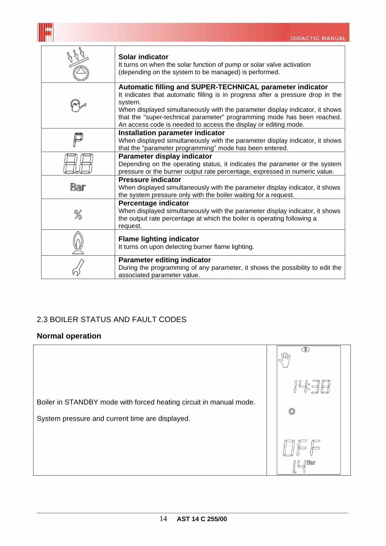
Solar indicator It turns on when the solar function of pump or solar valve activation (depending on the system to be managed) is performed.
Automatic filling and SUPER-TECHNICAL parameter indicator It indicates that automatic filling is in progress after a pressure drop in the system. When displayed simultaneously with the parameter display indicator, it shows that the "super-technical parameter" programming mode has been reached. An access code is needed to access the display or editing mode.
Installation parameter indicator When displayed simultaneously with the parameter display indicator, it shows that the "parameter programming" mode has been entered.
Parameter display indicator Depending on the operating status, it indicates the parameter or the system pressure or the burner output rate percentage, expressed in numeric value.
Pressure indicator When displayed simultaneously with the parameter display indicator, it shows the system pressure only with the boiler waiting for a request.
Percentage indicator When displayed simultaneously with the parameter display indicator, it shows the output rate percentage at which the boiler is operating following a request.
Flame lighting indicator It turns on upon detecting burner flame lighting.
Parameter editing indicator During the programming of any parameter, it shows the possibility to edit the associated parameter value.
2.3 BOILER STATUS AND FAULT CODES
Normal operation
Boiler in STANDBY mode with forced heating circuit in manual mode. System pressure and current time are displayed.
________________________________________________________________________________ 15 AST 14 C 255/00
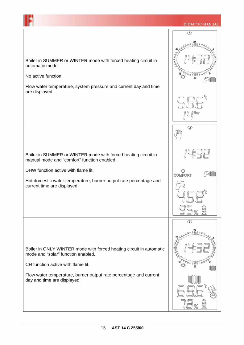
Boiler in SUMMER or WINTER mode with forced heating circuit in automatic mode. No active function. Flow water temperature, system pressure and current day and time are displayed.
Boiler in SUMMER or WINTER mode with forced heating circuit in manual mode and “comfort” function enabled. DHW function active with flame lit. Hot domestic water temperature, burner output rate percentage and current time are displayed.
Boiler in ONLY WINTER mode with forced heating circuit in automatic mode and “solar” function enabled. CH function active with flame lit. Flow water temperature, burner output rate percentage and current day and time are displayed.
________________________________________________________________________________ 16 AST 14 C 255/00
Malfunction, errors to be reset by user and self-resettable faults The display indicates the fault through the relevant error code (see following table). Some faults can be reset by pressing the "reset" key (r), some others are self-resettable (a) and reset only when the fault is resolved:
Boiler shut-down due to missing flame (r)
Boiler shut-down due to double flow probe triggering (r)
Boiler shut-down due to air pressure switch triggering (r)
Boiler shut-down due to too low system pressure (a)
Boiler shut-down due to double flow probe fault (a)
Warning: in case of self-resettable faults, only back-lighting of the LCD will remain active while the relevant error code will flash. In case of resettable faults, instead, the error is displayed in a steady way, and the "reset" key is enabled as well to reset boiler shut-down condition. In either case, once the fault has been resolved, back-lighting of all keys is enabled and after one minute (no other key being pressed) the interface is disabled.
________________________________________________________________________________ 17 AST 14 C 255/00
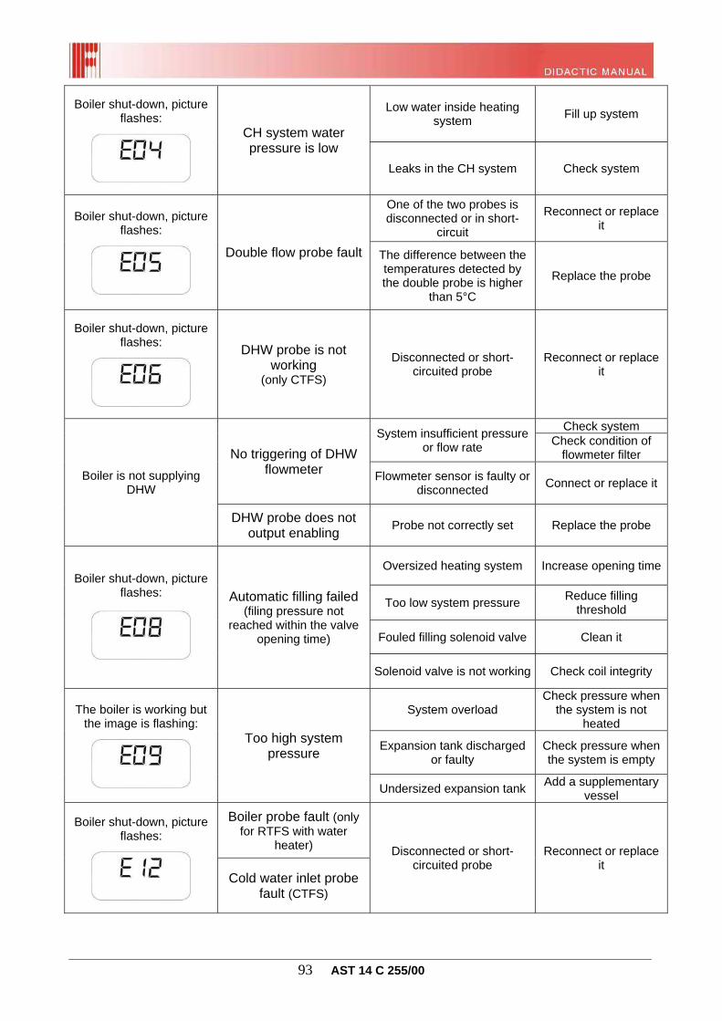
Boiler shut-down due to DHW probe fault (only for CTFS version) (a)
Automatic filling failed (only for CTFS version)
System pressure too high
Boiler shut-down due to boiler probe fault (RTFS combined with boiler) or DHW inlet probe (CTFS) (a)
External probe fault (a)
Solar collector probe fault (SCS) (a)
Solar valve probe fault (SVS) (a)
Solar water heating probe fault (SBS) (a)
Remote control connection fault (signalled only by remote control) (a)
Triggering of safety thermostat in mixed zone 2 (a)
Mixed zone 2 flow probe fault (a)
Mixed zone 3 flow probe fault (a)
Mixed zone 4 flow probe fault (a)
Communication failure between peripheral devices: interface or supplementary board (a)
Hydraulic configuration not allowed
Zone configuration error (remote, thermostat and ambient probes)
________________________________________________________________________________ 18 AST 14 C 255/00
Ambient probe 1 (a) fault
Ambient probe 2 (a) fault
Pressure transducer fault (a)
Communication error between main board and interface board
Shut-down due to safety circuit hardware fault
Air pressure switch recognition failure
Incompatibility between boiler board and interface board
Modulation coil fault (a)
Max. number of reset attempts from interface reached (r)
Max. number of reset attempts reached (signalled both by remote control and interface) (r)
NB: The board is able to count and store the boiler's latest five faults (both resettable and self-resettable). View them by scrolling super-technical parameters from P01 to P05.
________________________________________________________________________________ 19 AST 14 C 255/00
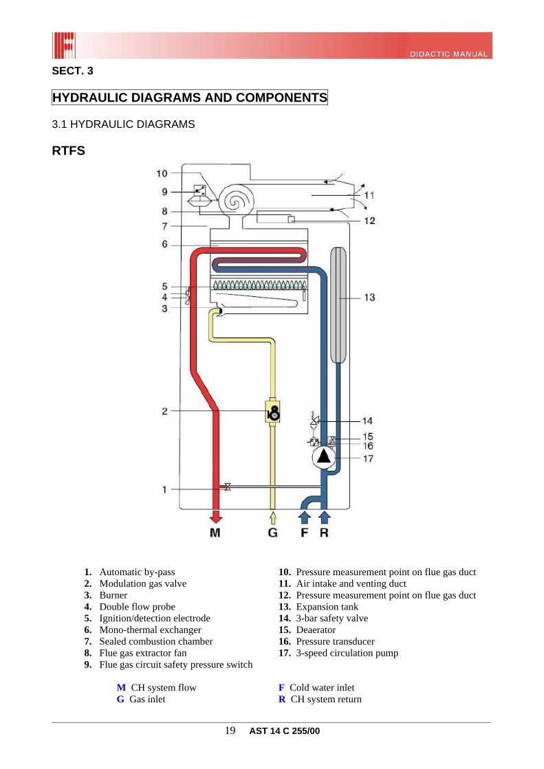
SECT. 3 HYDRAULIC DIAGRAMS AND COMPONENTS 3.1 HYDRAULIC DIAGRAMS RTFS
1. Automatic by-pass 10. Pressure measurement point on flue gas duct
2. Modulation gas valve 11. Air intake and venting duct 3. Burner 12. Pressure measurement point on flue gas duct 4. Double flow probe 13. Expansion tank 5. Ignition/detection electrode 14. 3-bar safety valve 6. Mono-thermal exchanger 15. Deaerator
7. Sealed combustion chamber 16. Pressure transducer 8. Flue gas extractor fan 17. 3-speed circulation pump 9. Flue gas circuit safety pressure switch
M CH system flow F Cold water inlet G Gas inlet R CH system return
________________________________________________________________________________ 20 AST 14 C 255/00
CTFS
1. Automatic by-pass 14. Pressure measurement point on flue gas duct 2. Domestic hot water temperature sensor 15. Expansion tank 3. Motorised 3-way valve 16. Cold water temperature sensor 4. Modulation gas valve 17. 3-bar safety valve 5. Burner 18. Deaerator 6. Double flow probe 19. Pressure transducer
7. Ignition/detection electrode 20. 3-speed circulation pump 8. Mono-thermal exchanger 21. Automatic filling solenoid valve 9. Sealed combustion chamber 22. Flow rate limiting device 10. Flue gas extractor fan 23. Filler cock 11. Flue gas circuit safety pressure switch 24. Cold water flowmeter with filter 12. Pressure measurement point on flue gas duct25. Insulated secondary plate exchanger 13. Air intake and venting duct
M CH system flow C Domestic hot water outlet G Gas inlet F Cold water inlet
R CH system return
________________________________________________________________________________ 21 AST 14 C 255/00
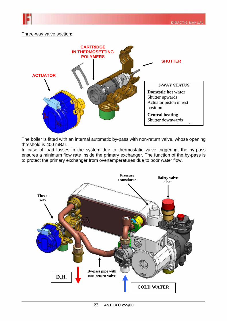
3.2 HYDRAULIC UNIT MOTORISED THREE-WAY VALVE (only for CTFS version) The boiler uses a three-way valve to divert the water flow coming from the primary exchanger into another pipe, in particular it diverts the water into the secondary (plate) exchanger, where heat will be transferred to the DHW. This valve consists of one main brass three-way body, one plastic (thermosetting polymers) cartridge, and one electric motor (actuator) to move the internal shutter.
The secondary exchanger is fixed by the three-way valve and another unit made of thermosetting polymers connecting the cold water inlet pipe to the rest of the hydraulic system. The stainless steel plate exchanger consists of 26 plates for all versions: 24, 28 and 32 kW. When domestic hot water is required, the cold water coming from the domestic water system passes through the flowmeter, setting the boiler to "DHW" mode. Then the three-way valve diverts the hot water coming from the primary exchanger into the secondary one so that it can transfer its heat to the plates for the instantaneous production of domestic hot water.
N.B. In rest condition, the three-way valve is in DHW mode position.
Electric motor
Water inlet from primary exchanger
Outlet to plate exchanger
Flow water
MOTOR CONNECTIONS ELECTRICAL
1 Line 1 Central heating 2 Neutral Domestic hot water
________________________________________________________________________________ 22 AST 14 C 255/00
Three-way valve section: The boiler is fitted with an internal automatic by-pass with non-return valve, whose opening threshold is 400 mBar. In case of load losses in the system due to thermostatic valve triggering, the by-pass ensures a minimum flow rate inside the primary exchanger. The function of the by-pass is to protect the primary exchanger from overtemperatures due to poor water flow.
COLD WATER
D.H.By-pass pipe with non-return valve
Pressure transducer Safety valve
3 bar
SHUTTER
CARTRIDGE IN THERMOSETTING
POLYMERS
3-WAY STATUS
Domestic hot water Shutter upwards Actuator piston in rest position
Central heating Shutter downwards A t t i t i ki
ACTUATOR
Three-way
________________________________________________________________________________ 23 AST 14 C 255/00
The circulation pump end block features one 3-position selector to set the motor rotation speed and thus the head to the system. The circulating pump is the same for all output rates, what varies (depending on the hydraulic circuit of the boiler) is the residual head curve:
RTFS 24 kW
CTFS 24 kW
RTFS 28 kW
V1
V2
V3
V1V2
V3
V1
V2
V3
Flow rate [l/h]
Ava
ilab
le h
ead
[ m
bar
]
CIRCULATION PUMP TECHNICAL SPECIFICATIONS Maximum head: 6 m Max. operating pressure: 6 bar Max. circulation temperature:95 °C
________________________________________________________________________________ 24 AST 14 C 255/00
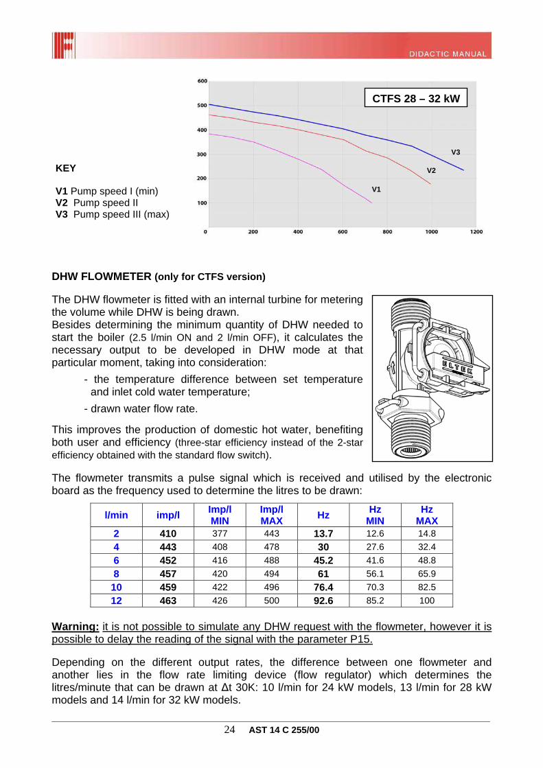
DHW FLOWMETER (only for CTFS version) The DHW flowmeter is fitted with an internal turbine for metering the volume while DHW is being drawn. Besides determining the minimum quantity of DHW needed to start the boiler (2.5 l/min ON and 2 l/min OFF), it calculates the necessary output to be developed in DHW mode at that particular moment, taking into consideration:
- the temperature difference between set temperature and inlet cold water temperature;
- drawn water flow rate.
This improves the production of domestic hot water, benefiting both user and efficiency (three-star efficiency instead of the 2-star efficiency obtained with the standard flow switch). The flowmeter transmits a pulse signal which is received and utilised by the electronic board as the frequency used to determine the litres to be drawn:
l/min imp/l Imp/l MIN
Imp/l MAX Hz Hz
MIN Hz
MAX 2 410 377 443 13.7 12.6 14.8
4 443 408 478 30 27.6 32.4
6 452 416 488 45.2 41.6 48.8
8 457 420 494 61 56.1 65.9
10 459 422 496 76.4 70.3 82.5
12 463 426 500 92.6 85.2 100
Warning: it is not possible to simulate any DHW request with the flowmeter, however it is possible to delay the reading of the signal with the parameter P15. Depending on the different output rates, the difference between one flowmeter and another lies in the flow rate limiting device (flow regulator) which determines the litres/minute that can be drawn at ∆t 30K: 10 l/min for 24 kW models, 13 l/min for 28 kW models and 14 l/min for 32 kW models.
KEY V1 Pump speed I (min) V2 Pump speed II V3 Pump speed III (max)
CTFS 28 – 32 kW
V1
V2
V3
________________________________________________________________________________ 25 AST 14 C 255/00
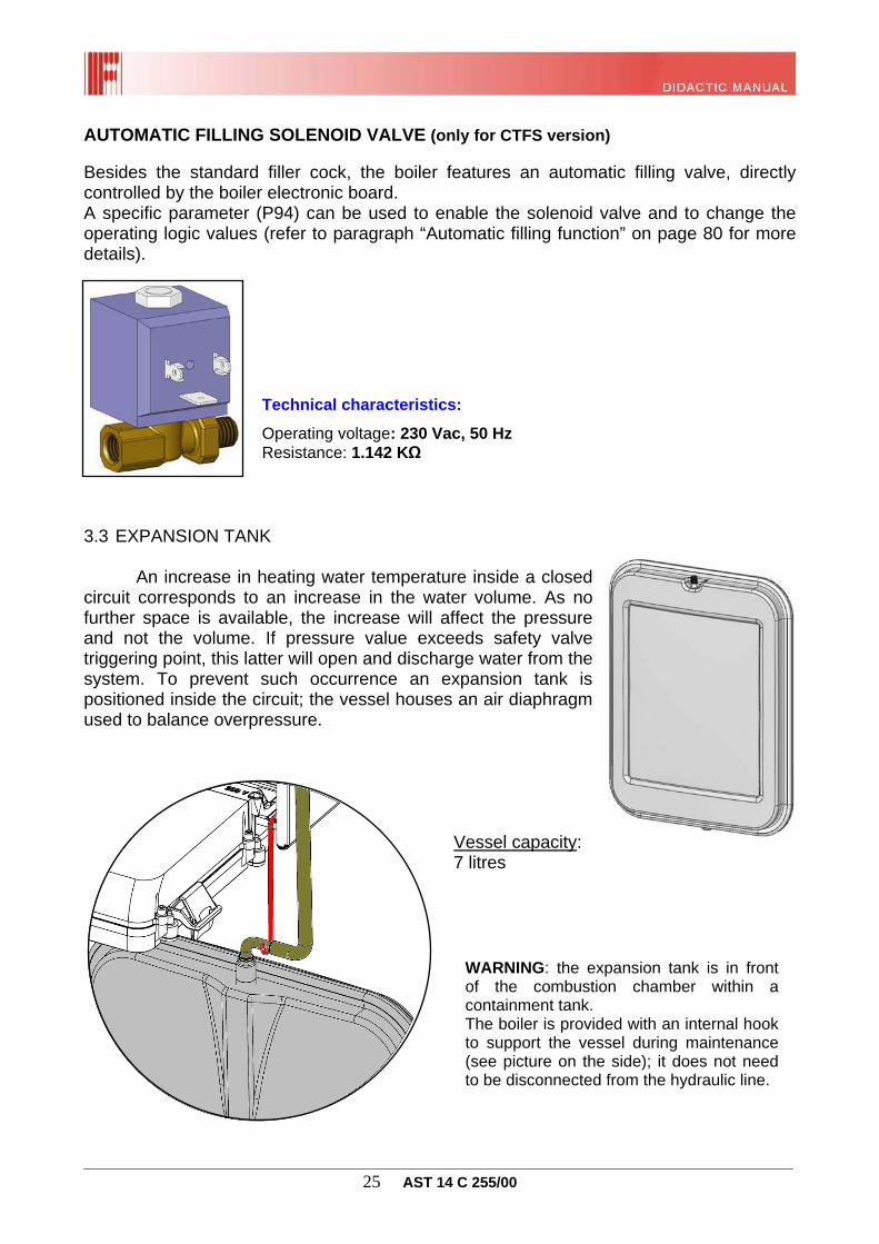
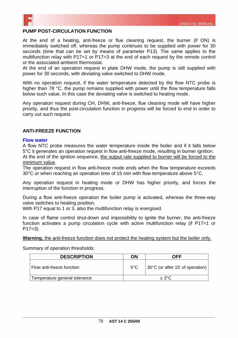
AUTOMATIC FILLING SOLENOID VALVE (only for CTFS version) Besides the standard filler cock, the boiler features an automatic filling valve, directly controlled by the boiler electronic board. A specific parameter (P94) can be used to enable the solenoid valve and to change the operating logic values (refer to paragraph “Automatic filling function” on page 80 for more details).
3.3 EXPANSION TANK An increase in heating water temperature inside a closed circuit corresponds to an increase in the water volume. As no further space is available, the increase will affect the pressure and not the volume. If pressure value exceeds safety valve triggering point, this latter will open and discharge water from the system. To prevent such occurrence an expansion tank is positioned inside the circuit; the vessel houses an air diaphragm used to balance overpressure.
Vessel capacity: 7 litres
WARNING: the expansion tank is in front of the combustion chamber within a containment tank. The boiler is provided with an internal hook to support the vessel during maintenance (see picture on the side); it does not need to be disconnected from the hydraulic line.
________________________________________________________________________________ 26 AST 14 C 255/00
3.4 HEAT EXCHANGERS PRIMARY EXCHANGER It is made up of a set of copper pipes, connected to each other in a way to create a "coil". The finning improves the efficiency of the heat exchange between the water flowing inside, the head developed by the burner flame and the hot combustion flue gases. The number of fins determines the type of exchanger used for the different output rates. Heat exchanger and the pipes are connected by means of special clips. Hydraulic sealing by pressure is ensured by O-rings applied to the specific pipes.
Warning: to replace the heat exchanger, proceed as follows:
- remove boiler front casing; - release the expansion tank (place it as shown in previous paragraph); - remove combustion chamber panel; - remove fan and flue gas hood; - release the sealing clips; - pull the exchanger upward to replace it; - refit all components, lubricate O-ring with care.
SECONDARY EXCHANGER (only for CTFS version) It is made up of a number of overlaying metal plates. In the spaces between the plates, the hot water coming from the CH circuit and the DHW system cold water flow simultaneously in separate circuits. The hot water will transfer its heat to the DHW system cold water. Therefore, at the outlet, the DHW will be warmer and the CH water (primary circuit) will be cooler. To prevent heat losses, particularly in the “COMFORT” mode (see paragraph on page 48), the heat exchanger is wrapped in a special insulating casing.
26 plates
FOR ALL POWER RATES
98 fins for 24 kW models
106 fins for 28 and 32 kW
________________________________________________________________________________ 27 AST 14 C 255/00
ELECTRICAL CONNECTIONS SOLENOID VALVES SV1 and SV2
3.5 GAS VALVE The boiler is approved for operating with gas valve, model SIT 845:
Gas valve characteristics EV1 and EV2 safety coil operating power supply 230 VAC 50 Hz
EV1 operating current 40 mA
EV2 operating current 12 mA
EV1 supply pin 4 - 5
EV2 supply pin 4 - 1
Modulation coil operating power supply 17 Vdc
Max. operating pressure 60 mbar
Working temperature -15 / 60°C
Modulation parameters
Current of gas modulation coil at maximum output 120 (natural gas) / 170 (LPG) mADC
Current of gas modulation coil at minimum output 20 (natural gas) / 30 (LPG) mADC Current of gas modulation coil at the end of the ignition ramp for CTFS boilers
80% of maximum current
Current of gas modulation coil at the end of the heating rising ramp
At maximum CH output (P7)
Coils Safety coil interchangeability Yes
EV1 resistance value ~ 1600 Ohm
EV2 resistance value ~ 6.77 KOhm
Modulating coil resistance value ~ 78 Ohm
The valve features a compensation pressure point connected to the combustion chamber through a silicone pipe. Valve thus knows the pressure on nozzles and can supply the correct quantity of gas even in case of overpressure or vacuum inside the chamber. For example, upon ignition when fan is activated, a vacuum develops inside the combustion chamber. Thanks to this pressure point, valve decreases nozzle pressure so as to balance any exceeding gas supply due to vacuum.
GAS OUT
GAS IN
Gas inlet pressure
measurement point E
Gas outlet pressure
measurement point D
________________________________________________________________________________ 28 AST 14 C 255/00
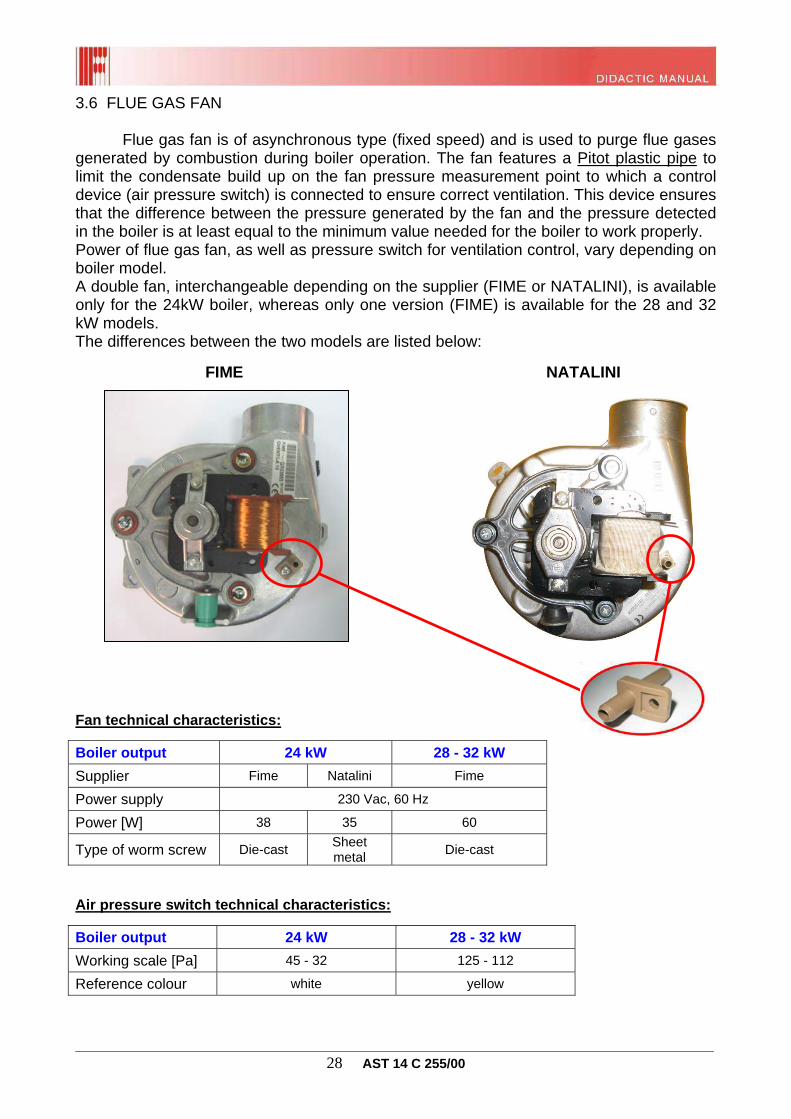
3.6 FLUE GAS FAN Flue gas fan is of asynchronous type (fixed speed) and is used to purge flue gases generated by combustion during boiler operation. The fan features a Pitot plastic pipe to limit the condensate build up on the fan pressure measurement point to which a control device (air pressure switch) is connected to ensure correct ventilation. This device ensures that the difference between the pressure generated by the fan and the pressure detected in the boiler is at least equal to the minimum value needed for the boiler to work properly. Power of flue gas fan, as well as pressure switch for ventilation control, vary depending on boiler model. A double fan, interchangeable depending on the supplier (FIME or NATALINI), is available only for the 24kW boiler, whereas only one version (FIME) is available for the 28 and 32 kW models. The differences between the two models are listed below:
FIME NATALINI
Fan technical characteristics:
Boiler output 24 kW 28 - 32 kW
Supplier Fime Natalini Fime
Power supply 230 Vac, 60 Hz
Power [W] 38 35 60
Type of worm screw Die-cast Sheet metal Die-cast
Air pressure switch technical characteristics:
Boiler output 24 kW 28 - 32 kW
Working scale [Pa] 45 - 32 125 - 112
Reference colour white yellow
________________________________________________________________________________ 29 AST 14 C 255/00
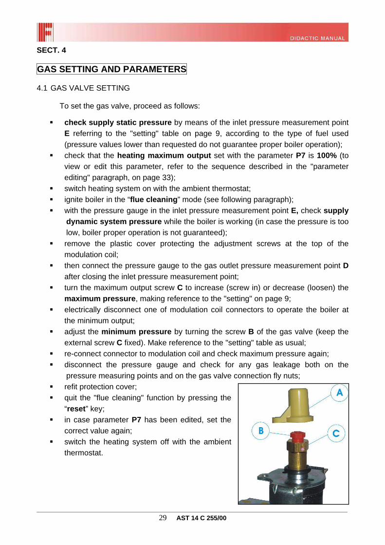
SECT. 4 GAS SETTING AND PARAMETERS 4.1 GAS VALVE SETTING To set the gas valve, proceed as follows:
check supply static pressure by means of the inlet pressure measurement point E referring to the "setting" table on page 9, according to the type of fuel used (pressure values lower than requested do not guarantee proper boiler operation);
check that the heating maximum output set with the parameter P7 is 100% (to view or edit this parameter, refer to the sequence described in the "parameter editing" paragraph, on page 33);
switch heating system on with the ambient thermostat; ignite boiler in the “flue cleaning” mode (see following paragraph); with the pressure gauge in the inlet pressure measurement point E, check supply
dynamic system pressure while the boiler is working (in case the pressure is too low, boiler proper operation is not guaranteed);
remove the plastic cover protecting the adjustment screws at the top of the modulation coil;
then connect the pressure gauge to the gas outlet pressure measurement point D after closing the inlet pressure measurement point;
turn the maximum output screw C to increase (screw in) or decrease (loosen) the maximum pressure, making reference to the "setting" on page 9;
electrically disconnect one of modulation coil connectors to operate the boiler at the minimum output;
adjust the minimum pressure by turning the screw B of the gas valve (keep the external screw C fixed). Make reference to the "setting" table as usual;
re-connect connector to modulation coil and check maximum pressure again; disconnect the pressure gauge and check for any gas leakage both on the
pressure measuring points and on the gas valve connection fly nuts; refit protection cover; quit the "flue cleaning" function by pressing the
“reset” key; in case parameter P7 has been edited, set the
correct value again; switch the heating system off with the ambient
thermostat.
________________________________________________________________________________ 30 AST 14 C 255/00
4.2 FLUE CLEANING FUNCTION The boiler features a flue cleaning function which must be used to measure combustion efficiency during operation and to set the burner. This function can be enabled only in the HEATING + DOMESTIC HOT WATER operating mode. To enable it, press “reset” key and keep it pressed for more than three seconds. Now the boiler will perform the ignition sequence and then operates at the burner maximum output set by parameter P7. The display will show simultaneously the current (mA) supplied to the modulation coil, the flow temperature, the system pressure, the lit flame symbol with burner on, the "broom" symbol to indicate that the flue cleaning function is active:
Use the “+” or “- DHW” keys to change the value of the current supplied to the modulation coil, form the minimum to the maximum value according to parameter P7. In this case, the display will show the wrench symbol (parameter editing indicator) and the value of the current supplied to the modulation coil being edited:
This operation is useful when setting the boiler combustion with closed casing. The desired output is set by pressing the DHW keys.
________________________________________________________________________________ 31 AST 14 C 255/00
The current supplied to the modulation coil at the minimum and at the maximum output values according to the gas used are given below:
max [mA]
min [mA]
Natural gas
120 20
LPG 170 30
Release the “+” or “- DHW” keys to return to the previous page showing the current at the modulation coil and the flow temperature. The burner is switched off when the temperature detected by the flow probe exceeds 90°C and switched on again when reaching 70°C. During such function the pump is supplied with power, the three-way valve switches to the heating position, and the multifunction relay is energised with parameter P17=1 (remote relay) or P17=3 (heating relay). The function automatically stops after 15 minutes, or by pressing the "reset" key, or setting a mode different from the “CH+DHW” one.
WARNING: the connected zone boards, if any, will also transfer the heat as a result of mixing valve setting, thus enabling the zone pump to maintain the flow set-point. 4.3 GAS CONVERSION Boilers are manufactured to run on the type of gas (natural gas or LPG) specifically required upon purchase order placing, and any conversion shall be made by qualified personnel.
During gas conversion, proceed as follows:
make sure to work with the boiler disconnected from the electric power supply; remove combustion chamber front panel; remove burner upper part concerning gas ramps; remove burner nozzles and replace them with new ones having a diameter
suitable for the new gas type (see "setting" paragraph on page 9).
WARNING: it is mandatory to fit the copper gaskets supplied along with the conversion kit;
refit burner and combustion chamber; supply the boiler with power; access parameter setting page, and set parameter P0 to the value suitable for the
type of gas used (refer to the sequence described in the "parameter editing" on page 33):
gas valve can now be set (paragraph 4.1). N.B. “Polidoro” burners feature as a standard nozzles without copper washers. It is mandatory to fit them during conversion. Failure to do so may affect the proper sealing.
________________________________________________________________________________ 32 AST 14 C 255/00
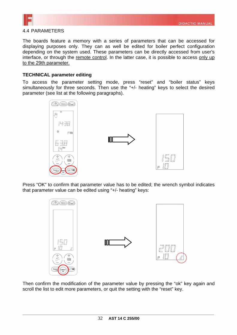
4.4 PARAMETERS The boards feature a memory with a series of parameters that can be accessed for displaying purposes only. They can as well be edited for boiler perfect configuration depending on the system used. These parameters can be directly accessed from user's interface, or through the remote control. In the latter case, it is possible to access only up to the 29th parameter. TECHNICAL parameter editing
To access the parameter setting mode, press “reset” and “boiler status” keys simultaneously for three seconds. Then use the “+/- heating” keys to select the desired parameter (see list at the following paragraphs).
Press “OK” to confirm that parameter value has to be edited; the wrench symbol indicates that parameter value can be edited using “+/- heating” keys:
Then confirm the modification of the parameter value by pressing the “ok” key again and scroll the list to edit more parameters, or quit the setting with the “reset” key.
________________________________________________________________________________ 33 AST 14 C 255/00
SUPER-TECHNICAL parameter editing
To access the super-technical parameter programming, proceed as described in the previous paragraph (press “reset” and “boiler status” keys simultaneously for three seconds). Super-technical parameters are in sequence after the 90th parameter.
The message “Cod” shows that a code must be entered (default 1398) with the “+ and – heating” keys (confirm each single number with the “ok” key).
After entering the correct entry code, an icon will be displayed, showing that the super-technical parameter area has been accessed. It is now possible to select and edit the desired parameters following the same procedure described in the previous paragraph (“ok” key to access the parameter and "+/- heating” key to change its value).
Then confirm the modification of the parameter value by pressing the “ok-info” key again and scroll the list to edit more parameters, or quit the setting with the “reset” key.
________________________________________________________________________________ 34 AST 14 C 255/00
Parameter display (read-only)
Press the “info” key several times to scroll in sequence the values of the parameters for displaying purposes only (from P30 to P50), such as the temperatures detected by the connected probes. To quit the displaying function, simply press “reset”. The start page will be displayed anyway 60 seconds after the last time the key has been pressed.
TECHNICAL parameter list
Parameter Range Default values Notes
P0 Boiler output selection (selection of "current-output" curve)
1 = combined instantaneous 2 = heating only 3 = with water heater
P6 Ignition output setting
0 to 100 % 0
0 = operation with ignition ramp; ≠ 0, ignition output identical to set output
P7 CH maximum output
10 to 100 % 100 10 = minimum output 100 = maximum output
P10 Heating curve
0 ÷ 3
(1=100) 1.5
With external probe: Low temp. from 0 to 0.8 High temp. from 1 to 3 Without external probe: Value < 1, reduced range for low temperature, from 35° to 45°C.
P11 Heating thermostat timing
0 to 10 min 4
P12 CH output rising ramp timing
0 to 10 min 1
P13 Timer for CH post-circulation, anti-freeze and flue cleaning function
30 to 180 s 30
P14 "Solar" DHW thermostat setting
0 ÷ 1 0 0 = normal 1 = solar
P15 Water hammer protection delay, configurable
0 to 10 s 0
P16 Ambient thermostat reading delay / OT
0 to 199 s 0
P17 Multifunction relay setting
0 ÷ 3 0
0 = shut-down and fault 1 = remote relay/TA1 2 = solar relay 3 = request TA2
________________________________________________________________________________ 35 AST 14 C 255/00
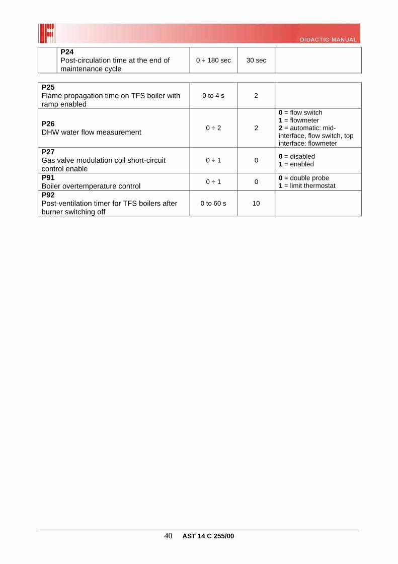
P27 Gas valve modulation coil short-circuit control enable
0 ÷ 1 0 0 = disabled 1 = enabled
P91 Boiler overtemperature control
0 ÷ 1 0 0 = double probe 1 = limit thermostat
P92 Post-ventilation timer for TFS boilers after burner switching off
0 to 60 s 10
________________________________________________________________________________ 41 AST 14 C 255/00
SECT. 5 OPERATING LOGIC 5.1 MAIN GENERAL CHARACTERISTICS
Function priority; Boiler type selection; Automatic flame control; Ignition with ramp or at pre-set output; DHW control; Plate DHW modulation; Boiler DHW modulation; DHW COMFORT function; CH control; Temperature range pre-selection; Ambient thermostat timer (antifast); Adjustable CH maximum output; Heating without ambient probe; Heating with ambient probe; Automatic operation; Heating modulation; Thermoregulation with ambient probe; Thermoregulation with external probe; Presetting for Remote Control; Programmable multifunction relay; Presetting for connection to supplementary boards; Temperature probe integrity check; Anti-shut-down function; Post-ventilation function; Pump post-circulation function; Anti-freeze function; Automatic filling function; Anti-legionella function; Gas proportional modulation coil integrity check; Safety devices and functions;
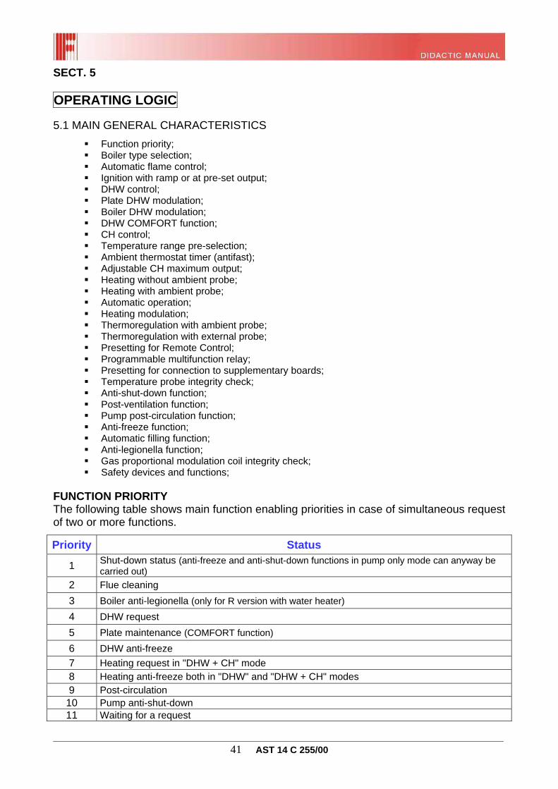
FUNCTION PRIORITY The following table shows main function enabling priorities in case of simultaneous request of two or more functions.
Priority Status
1 Shut-down status (anti-freeze and anti-shut-down functions in pump only mode can anyway be carried out)
2 Flue cleaning
3 Boiler anti-legionella (only for R version with water heater)
4 DHW request
5 Plate maintenance (COMFORT function)
6 DHW anti-freeze
7 Heating request in "DHW + CH" mode 8 Heating anti-freeze both in "DHW" and "DHW + CH" modes 9 Post-circulation
10 Pump anti-shut-down 11 Waiting for a request
________________________________________________________________________________ 42 AST 14 C 255/00
BOILER TYPE SELECTION Boiler type configuration; This board is preset to manage 3 different types of boiler configurations, depending on the setting of parameter P3:
P3 = 1 combi instant plates (model CTFS) P3 = 2 heating only (model RTFS) P3 = 3 with water heater (model RTFS with boiler management) Natural gas or LPG configuration This selection is obtained by setting parameter P0 (see previous section) to select the "current-output" curve to be applied to the gas proportional modulation coil in order to achieve the correct modulation:
24 kW:
24kW GPL TFS 24kW GPL TNCORRENTEMODULATORE[mA]
POTENZA[kW]
A
B
C
CORRENTEMODULATORE[mA]
POTENZA[kW]
A
B
C
D D
28 kW:
28kW GPL TFS 28kW GPL TNCORRENTEMODULATORE[mA]
POTENZA[kW]
A
B
C
CORRENTEMODULATORE[mA]
POTENZA[kW]
A
B
C
D D
32 kW:
32kW GPL TFSCORRENTEMODULATORE[mA]
POTENZA[kW]
A
B
C
D32kW GPL TNCORRENTE
MODULATORE[mA]
POTENZA[kW]
A
B
C
D
Warning: the “current-output” curve can be modified by moving point B through parameter P96 and point C through parameter P95.
LPG
LPG
LPG
Natural gas
Natural gas
Natural gas
________________________________________________________________________________ 43 AST 14 C 255/00
CTFS Configuration (forced draught) The type of boiler (sealed chamber or open chamber) is automatically recognised each time the board is supplied with power. The board attempts to read the inlets dedicated to the air pressure switch. During such phase, “CHA” will appear on the boiler display and upon the following recognition (which must take place within the first two minutes) C (sealed chamber) will be displayed for 5 seconds. No request will be performed during boiler type recognition. In case of wrong self-recognition, see the specific paragraph on page 82. Boiler hydraulic configuration (with P3=3) For heating-only boilers to which a DHW system is combined, the board is able to manage different hydraulic configurations through parameter P28 (default setting is 0) depending on system type. The two configurations allowed are listed below:
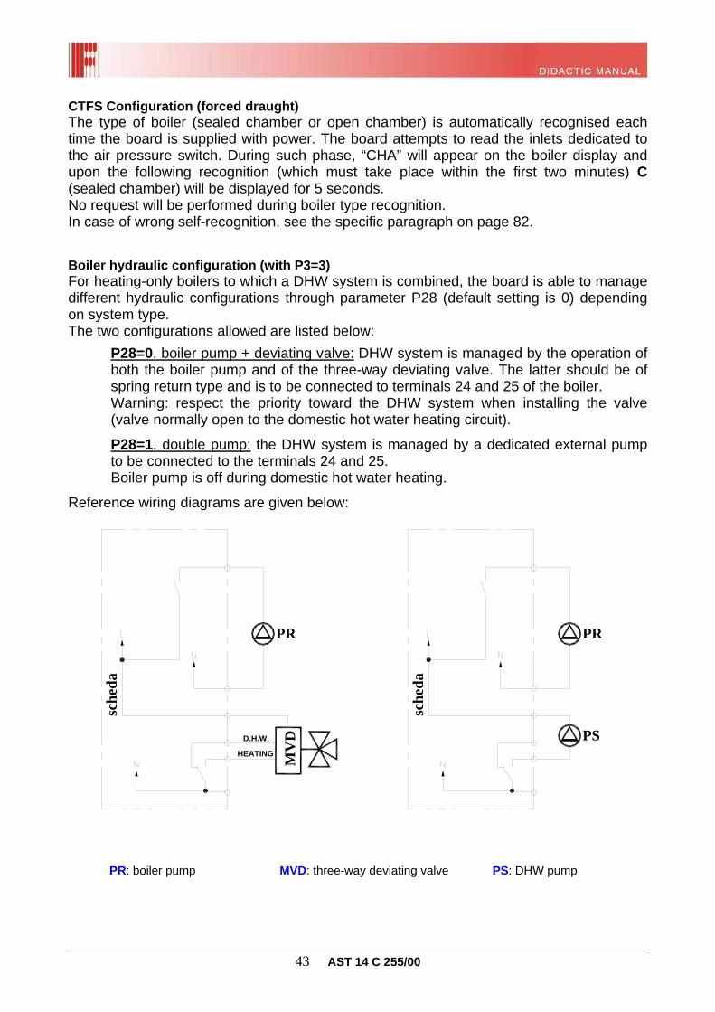
P28=0, boiler pump + deviating valve: DHW system is managed by the operation of both the boiler pump and of the three-way deviating valve. The latter should be of spring return type and is to be connected to terminals 24 and 25 of the boiler. Warning: respect the priority toward the DHW system when installing the valve (valve normally open to the domestic hot water heating circuit).
P28=1, double pump: the DHW system is managed by a dedicated external pump to be connected to the terminals 24 and 25. Boiler pump is off during domestic hot water heating.
________________________________________________________________________________ 44 AST 14 C 255/00
Ventilatore di combustione
ON/OFF
Elettrovalvola
Pressostato ariaTermostato fumi
Accensione
Rilevazione
Blocco
Tempo verifica pressostato ariao termostato fumi
TW tempo di attesa
Accensione del bruciatore
Bruciatore accesofunzionamento normale
Tempo di sicurezza TsBlocco
Funzioni
Tempi
AUTOMATIC FLAME CONTROL
The device is always enabled and constantly performs self-check functions. Upon an operation request, the fan is supplied with power after checking that the air pressure switch (C type) is in rest condition. As soon as the air pressure switch enabling is output, the flame control device starts measuring the waiting time TW (1.5 seconds); after such time, gas valve and igniter will be energised for a maximum safety time TS (10 seconds). If a flame is detected within such time, the gas valve is kept open (energised) and the igniter is cut-out.
Hereinafter is boiler operation logical diagram:
In case no flame is detected during an ignition attempt, the automatic flame control will repeat the ignition sequence, performing up to 5 ignition attempts, with a 10-second ventilation cycle to flush the chamber after each attempt. In case of flame detection, even if just for a moment, only one ignition attempt will be performed.
The flame control shut-down will be activated if no flame is detected within the TS safety time since the last ignition attempt, or if a parasitic flame (while the gas valve is not energised) is detected for over one minute. After 5 seconds, reset the shut-down status by pressing the “reset” key on the boiler board or on the remote control. WARNING: maximum 5 reset attempts are allowed, both from remote control and from the boiler interface. After such attempts, the error E98 or E99 will be displayed (no more shut-down-reset attempts allowed). Alarm counting is reset each time the board detects a flame or its power supply is interrupted.
________________________________________________________________________________ 45 AST 14 C 255/00
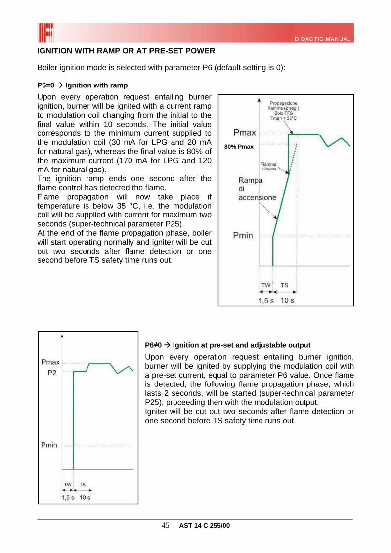
IGNITION WITH RAMP OR AT PRE-SET POWER Boiler ignition mode is selected with parameter P6 (default setting is 0): P6=0 Ignition with ramp
Upon every operation request entailing burner ignition, burner will be ignited with a current ramp to modulation coil changing from the initial to the final value within 10 seconds. The initial value corresponds to the minimum current supplied to the modulation coil (30 mA for LPG and 20 mA for natural gas), whereas the final value is 80% of the maximum current (170 mA for LPG and 120 mA for natural gas). The ignition ramp ends one second after the flame control has detected the flame. Flame propagation will now take place if temperature is below 35 °C, i.e. the modulation coil will be supplied with current for maximum two seconds (super-technical parameter P25). At the end of the flame propagation phase, boiler will start operating normally and igniter will be cut out two seconds after flame detection or one second before TS safety time runs out.
P6≠0 Ignition at pre-set and adjustable output
Upon every operation request entailing burner ignition, burner will be ignited by supplying the modulation coil with a pre-set current, equal to parameter P6 value. Once flame is detected, the following flame propagation phase, which lasts 2 seconds, will be started (super-technical parameter P25), proceeding then with the modulation output. Igniter will be cut out two seconds after flame detection or one second before TS safety time runs out.
80% Pmax
________________________________________________________________________________ 46 AST 14 C 255/00
DHW CONTROL With boiler running in “DHW” or “DHW + CH” mode, a flow rate exceeding 2.5 litres/minute within the flowmeter (CTFS version) or boiler programme enabling (RTFS version with water heater), generates a DHW operation request, thus starting "DHW modulation". The operation request in DHW mode has the priority over all other requests, and finishes when the previously mentioned electric contacts are opened again. WARNING: only for combined instantaneous versions (CTFS), with parameter P15, it is possible to delay the flowmeter reading for the DHW mode (from 0 to 10 seconds). PLATE DHW MODULATION (only for combined version, P3=1) Upon an operation request in plate DHW mode, if the water temperature read by the domestic hot water NTC probe is lower than the set-point value + 3°C (plate DHW thermostat triggering temperature ON), the burner ignition sequence is started with the automatic flame control enabling. Immediately after burner ignition, gas flow rate corresponds to flame modulation value which, thanks to a PID-type action, allows to reach and maintain the set DHW temperature. In case of poor heat output by the plate exchanger due to possible clogging and consequent overtemperature of the primary body, another PID-type setting on the flow line is added to the DHW modulation. Such operation occurs at a flow temperature higher than 81°C and disables when the flow temperature falls below 75°C. In presence of double modulation, the gas flow rate supplied to the burner corresponds to the lowest modulation value.
Modulation with P6=0
80% Pmax
________________________________________________________________________________ 47 AST 14 C 255/00
During DHW modulation, once the min. gas flow rate is reached and with the supplied output above the required one, the burner is switched off when DHW temperature reaches the + 5°C set-point value. After burner switching off, whilst the operation request is still present, burner will be ignited again when the temperature falls below the + 3°C set-point. During the first 20 seconds when the DHW is being drawn, to avoid boiler continuous "switch on/off", the maximum temperature allowed by the DHW probe to switch off the burner is set to 15°C higher than the set-point, whereas to switch it on again the temperature must fall below the + 8°C set-point. During the plate DHW modulation mode, the boiler pump is supplied with power and the deviating valve is in DHW position, whereas the multifunction relay is in the rest condition.
Warning: the burner is switched off also in case the flow probe detects a value of 85°C and then ignited again (with the request still present) only upon reaching 80°C. Plate DHW modulation temperatures:
DHW temperature setting range: 35 °C ÷ 57 °C DHW thermostat triggering temperature OFF = set point + 5°C DHW thermostat triggering temperature ON = set point + 3°C DHW thermostat triggering temp. initial draw (first 20 sec) OFF = set point + 15° C DHW thermostat triggering temp. initial draw (first 20 sec) ON = set point + 8° C Flow water thermostat triggering temperature with plate DHW mode: OFF 85° C Flow water thermostat triggering temperature with plate DHW mode: ON 80° C Flow water PID triggering temperature with DHW mode: 81° C Flow water PID deactivating temperature with DHW mode: 75° C
N.B. In case the boiler is combined with a solar plant with instantaneous-type integration, it is recommended setting parameter P14 to 1. This increases the modulation range, avoiding boiler hunting (start and stop) with inlet temperature very close to the set-point. In such case, the limit temperatures are as follows:
DHW thermostat triggering temp. OFF with instantaneous solar integr.: set-point + 10° C DHW thermostat triggering temp. ON with instantaneous solar integr.: set-point + 9° C
BOILER DHW MODULATION (only for RTFS version with water heater, P3=3) With boiler running in “DHW” or “DHW + CH” mode, the boiler programme enable time generates a request in DHW mode. If the water heater temperature read by the NTC probe is lower than the boiler priority thermostat ON triggering temperature (set-point - 3°C) set either through boiler or through remote control and the flow temperature is lower than 70°C, the burner ignition sequence is started with the automatic flame control section enabling. At the end of this sequence, the power supplied to the burner corresponds to the flame modulation value which, thanks to a PID-type action, allows to reach and maintain the flow modulation temperature in boiler mode. Such temperature is calculated according to the requested boiler temperature and of the current temperature read by the probe, and shall in any way lie within a lower value (corresponding to "requested boiler temperature + 10°C”) and a higher value (85°C). Max. flow modulation occurs when the difference between requested boiler temperature and current boiler temperature is higher or equal to 10°C.
________________________________________________________________________________ 48 AST 14 C 255/00
During boiler heating phase:
- with P28 = 0 (pump and deviating valve), the boiler pump is supplied with power whereas the deviating valve is in DHW position;
- with P28 = 1 (heating pump and DHW pump), the heating pump is off whereas the DHW pump is supplied with power;
while the multifunction relay is in the rest condition. Boiler DHW modulation temperature:
DHW temperature setting range: 35 °C ÷ 65 °C Boiler priority thermostat triggering temperature OFF = set-point + 0 °C Boiler priority thermostat triggering temperature ON = set-point - 3 °C Max. flow modulation temperature in boiler mode = 85° C Minimum temperature difference between requested boiler and flow modulation
temperatures = 10° C Temperature difference between requested and current boiler temperatures for max. flow
modulation = 10° C Temperature difference between requested and current boiler temperatures for min. flow
modulation = 0° C Flow water thermostat triggering temperature in DHW mode - boiler OFF = 86° C Flow water thermostat triggering temperature in DHW mode - boiler ON = 70° C
DHW COMFORT FUNCTION In the CTFS version (combined instantaneous) with P3=1, plate exchanger maintenance function can be enabled and disabled with the "COMFORT-ok” key to achieve the three-star efficiency when the boiler is in DHW mode. When this function is enabled, "COMFORT” will appear on the boiler display and the maintenance cycle described below is limited by the super-technical parameters (from P20 to P25).
Operating logic: maintenance comes into operation only if the temperature read by the DHW probe is lower than the set hot water temperature (Tset_san) minus the value of super-technical parameter P20 (default 14°C) and in case the time elapsed since the last maintenance cycle is longer than the time set by P21 (default 10 min):
Tset_San < (Tset_San – P20st) and Temp_maintenance P21
If this condition occurs, a pump pre-circulation cycle is performed for a time equivalent to P22st (default 30 seconds). After this pre-circulation, the burner will ignite if the temperature read by the flow probe (Tman) is lower than Tset_san + P20st. In case of burner ignition, burner will be switched off as soon as Tman flow temperature exceeds Tset_san + P23st value, with the subsequent pump post-circulation for a time equivalent to P24st (default 30 seconds). For the RTFS versions (heating only fitted with a boiler), the COMFORT function enabled with P3=3 allows to bypass the programming reserved to water heater, thus allowing for domestic hot water heating also outside set time slots. When said function is disabled, the boiler will resume the programme-managed control of water heater.
________________________________________________________________________________ 49 AST 14 C 255/00
CH CONTROL The boiler electronics features a "timer" function for the weekly programming of heating times (automatic operation). This function can be used to manage separately up to two zones and the relevant signals are connected to the boiler board, which features two inputs for the connection of the standard ambient thermostats and one remote control. The interface board features two inputs to manage the climate control of each zone using the specific ambient probes. Use parameter P61 to associate the zone with the relevant climate control device (thermostat or remote control or ambient probe). Use of an ambient probe (even just one) must be enabled with parameter P57 (probe presence). To use two ambient probes, it is necessary to add a zone board (enter the number of supplementary boards present using parameter P60), as the multifunction relay integrated in the board can manage one single circuit. Using parameters P57, P60 and 61 it is therefore possible to manage different solutions, depending on the requirements. In case of wrong parameter configuration, the error E43 will be displayed.
Warning: in case of particularly "complex" zone systems, refer to instruction manual supplied along with the zone board kit. In any case, it is not possible to manage more than four zones (taking into account boiler board and supplementary boards). It should also be pointed out that the automatic programming from the boiler is allowed only for the first two circuits (zones). TEMPERATURE RANGE PRE-SELECTION
With parameter P10, without any external probe, it is possible to set two ranges (standard or reduced) in order to adjust the flow water by means of the boiler keys or the remote control:
P10 < 1 heating temperature reduced range: 35 ÷ 45°C P10 ≥ 1 heating temperature standard range: 35 ÷ 78°C
Using an external probe, instead, such parameter corresponds to the thermoregulation curve selection (see paragraph “Thermoregulation with external probe”). AMBIENT THERMOSTAT TIMER (ANTIFAST)
During modulation in heating mode, after burner switching off, wait 240 sec (parameter P11). After that, if the flow temperature is lower than the “set-point”, the burner is switched on again.
Besides, the heating thermostat timer is reset:
upon a DHW request; at the end of a heating request; selecting the “standby” or “DHW” mode or resetting the boiler; if the flow water temperature value falls below the parameter P27 (40°C with
standard range, or 35°C with reduced range).
________________________________________________________________________________ 50 AST 14 C 255/00
ADJUSTABLE HEATING MAXIMUM OUTPUT
During operation in heating mode, the maximum output supplied to the burner is equal to the one set by parameter P7. This parameter represents the percentage (default 100%) of maximum admissible current supplied to the modulation coil (120 mA for natural gas and 170 mA for LPG). CH WITHOUT AMBIENT PROBES (P57=4)
With the boiler set on the "DHW + CH" or "Heating only" operating mode, the closing up of ambient thermostat electric contact (or the enabling signal from the remote control) will result in a request in the heating mode, making heating modulation start. It is possible either to manage the heating zones with the relevant control devices only (manual operation), or to set the heating times (automatic operation) of zones 1 and 2 directly from the boiler. In the latter case, the "timer" function is logically connected in series with the inputs of the climate control devices.
WARNING: with parameter P16 it is possible to delay the ambient thermostat reading to allow the zone valves (if available) to open before the boiler pump starts (from 0 to 199 seconds). CH WITH AMBIENT PROBES (P57≠4)
To allow for managing the heating zones using the ambient probes, they have to be enabled, i.e. value of parameter P57 must be different from 4. Ambient probe 1 (SA1) is associated with zone 1 and with heating programme 1, whereas ambient probe 2 (SA2) is associated with zone 2 and with heating programme 2.
WARNING: it is possible to connect two ambient probes only if a zone supplementary board is present, otherwise it is not possible to manage ambient probe 2 (SA2). Operating logic
The CH function is enabled only if the boiler is in the "DHW + CH” or “Heating only” mode. The “Ambient set-point” setting is on two levels: daytime temperature and night-time temperature, represented respectively by the symbols and . During manual operation, only the daytime level is taken into account, while in the automatic operation (weekly programming) the levels correspond to the enable/disable times. Ambient probe requests heat when ambient temperature is lower than or equal to “Ambient set-point” minus “triggering differential ON” value (parameter P52 for SA1 and P55 for SA2). Request stops when ambient temperature is higher than or equal to “Ambient set-point” plus “triggering differential OFF” value (parameter P51 for SA1 and P53 for SA2).
Example:
Tset-point SA1=20°C ; P51=0.2; P52=-0.3
Heating is enabled when ambient temperature SA1 ≤ 19.7 Heating is disabled when ambient temperature SA1 ≥ 20.2
________________________________________________________________________________ 51 AST 14 C 255/00
In case of probes not correctly set or installed in an improper position, the ambient probe reading can be corrected with the parameters P53 (for SA1) and P56 (for SA2). Ambient probe value is the result of the value read by ambient probe plus or minus the value of the two parameters given above (from -5°C to +5°C). WARNING: in case the probes are damaged (short-circuit, open circuit or out of range value) error E44 will be displayed for SA1 and error E45 for SA2. Any active heating circuit(s) will be interrupted. In case two ambient probes are used, the setting of daytime and of night-time temperatures must be the same for both probes. To set different temperatures, it is necessary to correct the reading with the specific parameters.
Modulation types with ambient probe
By setting parameter P57, it is possible to use the ambient probes and have the boiler work in CH mode using the type of modulation which is most suitable for the system. The differences are given below, pre-condition being that the two zones must be managed at the same temperature, with ambient probe (zone1) and heating thermostat (zone2) respectively. According to the above described condition, parameters P17, P60 and P61 must be set to 1, 0 and 03 respectively. P57=0 Modulation on-off
In this case, an external probe is not necessary and flow temperature is set with “+/- heating" key at fixed point (35-45°C or 35-78°C) for both circuits. P57=1 Ambient probe modulation
External probe is not necessary. Zone 2 works at a fixed temperature selected with "+/- heating” key (35-45°C or 35-78°C) and follows programme 2. Instead, the set-point requested by zone1 (ambient probe) is calculated according to the temperature detected by the probe, and of the “Sun or moon temperature” selected in the heating programme 1. In case both zones request heat, the flow set-point calculated will be the highest of the two requested. P57=2 External probe modulation
In this case, it is necessary to use the external probe with the relevant thermoregulation curve setting (P10). Zone 2 works at sliding temperature, calculating the set-point as a function of the external temperature, of the set curve and of the "Fictitious ambient temperature" set with “+/- heating” key, according to the specific programme. Instead, the set-point requested by the ambient probe (zone1) is calculated as a function of the external temperature, of the set curve and of the “Day and night temperatures” selected in the heating programme 1. In case both zones request heat, the flow set-point calculated will be the highest of the two requested. P57=3 Ambient probe and external probe modulation
Also in this case, the use of the external probe is necessary,with the relevant setting of the thermoregulation curve (P10).
________________________________________________________________________________ 52 AST 14 C 255/00
Zone 2 works at sliding temperature, calculating the set-point as a function of the external temperature, of the set curve and of the "Fictitious ambient temperature" set with “+/- heating” key, according to the specific programme. Instead, the set-point requested by the probe (zone1) is calculated as a function of the external temperature, of the ambient temperature, of the set curve, of the constant "K" (P58) and of the “Day and night temperatures” selected in the heating programme 1. In case both zones request heat, the flow set-point calculated will be the highest of the two requested.
N.B: For set-point calculation according to modulation of external probe, of ambient probe or of both, refer to the specific paragraphs on page 55 and 56.
Ambient probe configuration errors
In case of a wrong connection of the probes to the relevant inputs and particularly in the case of not allowed configuration between parameters P57, P60 and P61, the fault is signalled with the relevant error code E43, resulting in heating circuit disabling (if operating). The most common errors that can lead to this fault are connected with the use of the supplementary zone board and of the remote control. A summary of the allowed configurations is listed below:
1 0 0 1 configuration not allowed 1 0 1 0 configuration not allowed E43 1 0 1 1 configuration not allowed E43 1 1 0 0 configuration not allowed E43 1 1 0 1 ≠ 4 1 ÷ 4 04 1 1 1 0 configuration not allowed E43 1 1 1 1 configuration not allowed E43
Key: 1 = present 0 = absent
Warning: the use of a supplementary zone board is mandatory when using a double ambient probe or when adding a remote control. AUTOMATIC OPERATION The interface features a weekly hour programming for maintaining the water heater (RTFS version) and for activating the heating at the desired times in association with each single zone: one for the TA1 input and one for the TA2 input.
________________________________________________________________________________ 53 AST 14 C 255/00
The "sun" symbol (with indication of the lit bars) indicates that heating is enabled; whereas the "moon" symbol (bars off) indicates disabling periods. The hour programming is logically in series with the ambient thermostat inputs. This means that the boiler will perform heating only if the TA contact is closed and if the programming is in the enabled periods (sun). Programmes and zones are associated by parameter P61. In presence of the remote control and without supplementary boards, the associated zone is always zone1. When a remote control is connected, the hour programming of the associated zone (and of the water heater if available) will not be shown by the boiler display as it is set directly through remote control.
Programming procedure
To access programme display or editing mode, press “PROG” key repeatedly:
- , press twice to access heating programme for zone 1;
- , press three times to access heating programme for zone 2;
- , press four times (only for RTFS with P3=3) to access the programme for maintaining water heater.
Each time the “PROG” key is pressed, its icon flashes displaying the programme to which access is required (displaying the current operation period). Press the “ok” key to access actual programming. Then select the day(s) of the week to be edited using the “+/- heating” key and confirming as usual with the “ok” key (the icon associated to the day(s) will stop flashing and will remain on steady).
It is now possible to associate the day/night level (by means of the “sun/moon” key) with the desired time, using the “+/- heating” key: In case single days are programmed, when exceeding the 24 h use the “+/- heating" key and the system will automatically switch to the next day without having to repeat the whole sequence. Press the "reset" key to change day or programme immediately. Press it twice repeatedly to quit the programme completely and return to the main page.
________________________________________________________________________________ 54 AST 14 C 255/00
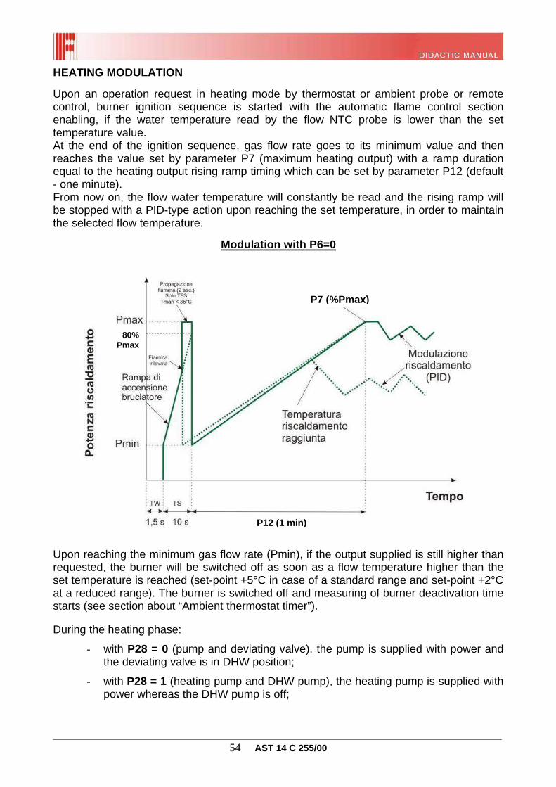
HEATING MODULATION
Upon an operation request in heating mode by thermostat or ambient probe or remote control, burner ignition sequence is started with the automatic flame control section enabling, if the water temperature read by the flow NTC probe is lower than the set temperature value. At the end of the ignition sequence, gas flow rate goes to its minimum value and then reaches the value set by parameter P7 (maximum heating output) with a ramp duration equal to the heating output rising ramp timing which can be set by parameter P12 (default - one minute). From now on, the flow water temperature will constantly be read and the rising ramp will be stopped with a PID-type action upon reaching the set temperature, in order to maintain the selected flow temperature. Upon reaching the minimum gas flow rate (Pmin), if the output supplied is still higher than requested, the burner will be switched off as soon as a flow temperature higher than the set temperature is reached (set-point +5°C in case of a standard range and set-point +2°C at a reduced range). The burner is switched off and measuring of burner deactivation time starts (see section about “Ambient thermostat timer”). During the heating phase:
- with P28 = 0 (pump and deviating valve), the pump is supplied with power and the deviating valve is in DHW position;
- with P28 = 1 (heating pump and DHW pump), the heating pump is supplied with power whereas the DHW pump is off;
Modulation with P6=0
P7 (%Pmax)
P12 (1 min)
80% Pmax
________________________________________________________________________________ 55 AST 14 C 255/00
- with P17 = 1 (multifunction relay in remote relay/TA1), the relay is energised in response to a request from the remote control or from TA1 and returns to the rest condition upon a DHW request or in case the boiler is switched OFF or to DHW ONLY mode;
- with P17 = 3 (multifunction relay in TA2 request), the relay is energised in response to a request from TA2 and returns to the rest condition upon a DHW request or in case the boiler is switched OFF or put into DHW ONLY mode;
During the operation in heating mode, upon any DHW request, the latter has higher priority and forces the interruption of the function in progress. CH modulation temperature - standard range (P10≥1):
CH temperature setting range: 35÷78°C CH thermostat triggering temperature OFF = set-point + 5° C CH thermostat triggering temperature ON = set-point + 0° C Heating thermostat timer (antifast) - can be set through P11: 0÷10 min, default 4 min with
Tflow > P27 CH thermostat timer reset temperature through parameter P27: 35÷78°C, default 40°C Heating output rising ramp timing by means of parameter P12: 0÷10 min, default 1 min
Heating modulation temperature reduced range (P10<1):
Heating temperature setting reduced range: 35÷45°C Reduced CH thermostat triggering temperature OFF = set-point + 2° C Reduced CH thermostat triggering temperature ON = set-point - 2° C Heating thermostat timer (antifast) - can be set through P11: 0÷10 min, default 4 min with
Tflow > P27 CH thermostat timer reset temperature through parameter P27: 35°C fixed Heating output rising ramp timing by means of parameter P12: 0÷10 min, default 1 min
The set-point depends on the setting of the heating temperature through the boiler keys or the temperature set through remote control. THERMOREGULATION WITH AMBIENT PROBE Flow water temperature value is set differently depending on the type of ambient modulation to be set
With P57=0 (on - off-type modulation) flow set-point is set with the “+/- heating” keys; With P57=1 (ambient probe modulation) flow set-point is calculated according to parameter P10 according to the following formula:
With P57=2 (external probe modulation) refer to next section;
________________________________________________________________________________ 56 AST 14 C 255/00
With P57=3 (ambient probe and external probe modulation) flow set-point value is calculated according to the external probe and to the selected curve (as with P57=2), plus the following value:
∆Tflow = Curve*K*∆Tambient where,
∆Tflow = value to be added to the calculation of flow with external probe; Curve = curve set value (P10) K = constant indicating ambient probe weight given by parameter P58 (default 8) ∆Tambient = difference between set temperature and temperature read by the ambient probe.
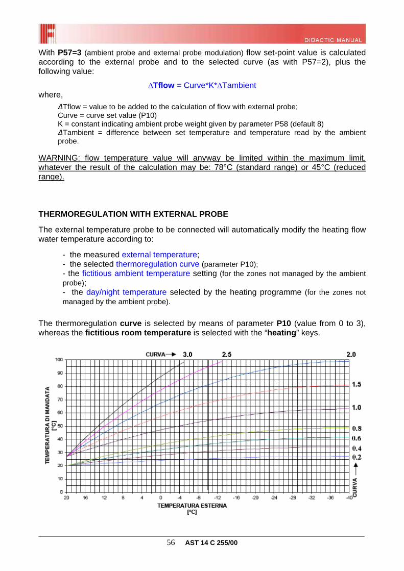
WARNING: flow temperature value will anyway be limited within the maximum limit, whatever the result of the calculation may be: 78°C (standard range) or 45°C (reduced range). THERMOREGULATION WITH EXTERNAL PROBE
The external temperature probe to be connected will automatically modify the heating flow water temperature according to:
- the measured external temperature; - the selected thermoregulation curve (parameter P10); - the fictitious ambient temperature setting (for the zones not managed by the ambient
probe); - the day/night temperature selected by the heating programme (for the zones not
managed by the ambient probe).
The thermoregulation curve is selected by means of parameter P10 (value from 0 to 3), whereas the fictitious room temperature is selected with the “heating” keys.
________________________________________________________________________________ 57 AST 14 C 255/00
The board independently detects the presence of the external temperature probe and enables the thermoregulation function, by keeping the flow temperature within the heating temperature pre-selection range (35 °C ÷ 78 °C or 35 °C ÷ 45 °C).
If both the external probe and the remote control are present, assuming that the remote control is able to set and carry out its own thermoregulation, the modulation board transmits the external temperature value to the remote control, and if the heating request is determined by the same control, this will determine the flow temperature according to its thermoregulation curve and to the room temperature previously set. Otherwise, if the heating request comes simultaneously from the remote control and the amb. T. contact closing on the board, both the remote control and the modulation board independently calculate the flow temperature according to relevant thermoregulation curves and set ambient temperatures. The highest of the two flow temperature values will be used. Thermoregulation curve setting
To access the parameter setting mode, press “reset” and “boiler status” keys simultaneously for three seconds.
Use “+/- heating” keys, to select parameter P10. Press “OK” to confirm that parameter value must be edited (the wrench symbol indicates that parameter value can be edited using keys “+/- heating”):
For high temperature systems, it is recommended to set parameter P10 to a value between 1 and 2.
For low temperature systems, it is recommended to set parameter P10 to a value
between 0.2 and 0.8. Then confirm the modification of the parameter value by pressing the “ok-COMFORT” key and quit programming with the “reset” key.
________________________________________________________________________________ 58 AST 14 C 255/00
The curves given in the above diagram refer to a request of a “fictitious ambient temperature” of 20°C. In case of different fictitious temperature, all curves are shifted in a parallel translation: Example of curve shifting with P10=1.5 and ambient fictitious temperature from 20 to 25°C. Curves can be chosen proceeding either roughly and approximately or using a simple mathematical formula. In either case, it will be necessary to check the temperature changes so as to correct and choose the proper curve accurately.
In the former case you will simply need to take an actual value of external temperature and associate the desired flow value to it. Then choose the closest curve. Example:
at an external temp. of -4°C, a flow of 62°C is required; curve: 1.5
In the latter case use the following formula:
CURVETestmin 20
20 Tmax
Where, Tmax is the maximum flow temperature and Textmin is the minimum external temperature. Example: Low temperature: High temperature:
Tmax = 44°C Tmax = 70°C Text = -10°C Text = -10°C
CURVE (-10) 20
20 44
CURVE (-10) 20
20 70
P10 curve = 0.8 P10 curve = 1.7
+5
-5
________________________________________________________________________________ 59 AST 14 C 255/00
Checking the thermoregulation curve setting
It takes time to choose the best curve. Consider the following suggestions:
if upon external temperature decrease the room temperature increases, it is necessary to set a curve with a lower slope, i.e. a lower curve;
if upon external temperature decrease the room temperature decreases, it is necessary to set a curve with a higher slope, i.e. a higher curve;
Lastly, if the room temperature remains constant upon changing of the external temperature, the curve is correct.
If the room temperature is constant but different from the desired value it is necessary to translate the curve. This occurs automatically by pressing the “+/- heating” keys on the boiler panel. In fact, with an external probe installed, such keys do not adjust the flow temperature as usual but the desired fictitious temperature ranging from 5°C to 30°C. It is recommended to set a value between 20°C and 25°C, or at least similar to the value set by the ambient thermostat. REMOTE CONTROL PRE-SETTING The board is provided with an internal interface that allows the connection of an OpenTherm protocol-based remote control. This latter, besides serving as an ambient thermostat for its zone, allows to set some of the boiler main parameters. Connect the remote control to the board with two non-polarised conductor. When the connection is done, “Con” will appear on the boiler LCD display. Instead of the remote control, an ambient thermostat connection (clean contact) is arranged: when closed for more than 10 seconds, it generates a heating request for the zone managed by the remote control. The request stops when the contact remains open for more than one second. When the remote control is not connected and/or does not communicate, all settings are made from the boiler. Board and remote control communicate in each operating mode: DHW, DHW+CH, CH or STANDBY. A communication loss will entail the continuous attempt to restore it but, after 1 minute, the board will resume operation in local mode until connection is restored. In this case the system temporarily ignores the heating request that could be generated by a possible contact connected on opentherm. When the connection is active, remote control has a priority over boiler switch, and it enables/disables DHW and CH functions. The remote control can request the boiler and display the flow, DHW, external probe temperatures, the temperatures set for DHW and heating, the current modulation level, as well as the error code. It can also display the different operation states (DHW, heating, flame lighting, fault presence or shut-down) and it can reset the boiler after a shut-down for a limited number of times and period (no more than 3 times in 24 hours). Warning: the remote control allows access only to the first 29 parameters.
________________________________________________________________________________ 60 AST 14 C 255/00
PROGRAMMABLE MULTIFUNCTION RELAY The boiler is fitted with a multifunction relay (230 Vac, 10A cos1) which can be associated to a different function by setting parameter P17:
P17=0 Alarm reference
Upon each shut-down or fault the relay is energised:
Electrical connections:
P17=1 Remote control reference
Upon each request from the remote control (or TA1), the relay is energised:
Electrical connections:
P17=3 Ambient thermostat reference
Upon each request from the ambient thermostat TA2, the relay is energised:
Electrical connections:
21 22 23 21 22 23
21 22 23
21 22 23
________________________________________________________________________________ 61 AST 14 C 255/00
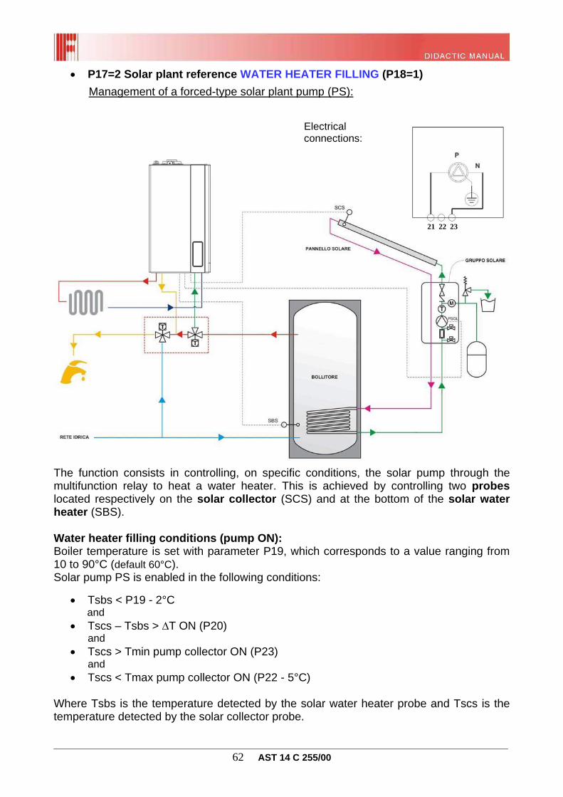
P17=2 Solar plant reference: BOILER INTEGRATION (P18=0) only for CTFS
Management of a solar plant deviating valve (VM):
The function consists in properly controlling the motorised valve VM by means of
the multifunction relay and in activating the boiler burner only if the solar water heater temperature is sufficient to fulfil the request for operation. This valve is controlled by a solar water heating probe (SBS) located at the water heater output. The VM valve remains in the rest condition (boiler integration) when the temperature detected by the SBS probe is lower than the DHW set-point temperature - 2°C. Instead, it is supplied with power (solar-only mode) when the solar water heating probe temperature reaches the DHW set-point set in the boiler, or in case of probe fault. When the VM valve is in solar-only mode, the boiler will not perform the DHW function.
Warning: said function is active only if either the DHW + CH, or the CH ONLY or DHW ONLY mode is selected in the boiler. With boiler in OFF or ANTI-FREEZE mode, the VM valve is constantly supplied with power. Any probe faults are reported in the boiler interface or on the remote control through the relevant error code (E28).
Electrical connections:
VM
21 22 23 21 22 23
________________________________________________________________________________ 62 AST 14 C 255/00
P17=2 Solar plant reference WATER HEATER FILLING (P18=1)
Management of a forced-type solar plant pump (PS):
The function consists in controlling, on specific conditions, the solar pump through the multifunction relay to heat a water heater. This is achieved by controlling two probes located respectively on the solar collector (SCS) and at the bottom of the solar water heater (SBS). Water heater filling conditions (pump ON): Boiler temperature is set with parameter P19, which corresponds to a value ranging from 10 to 90°C (default 60°C). Solar pump PS is enabled in the following conditions:
Tsbs < P19 - 2°C and
Tscs – Tsbs > ∆T ON (P20) and
Tscs > Tmin pump collector ON (P23) and
Tscs < Tmax pump collector ON (P22 - 5°C) Where Tsbs is the temperature detected by the solar water heater probe and Tscs is the temperature detected by the solar collector probe.
Electrical connections:
PS
PS
21 22 23
________________________________________________________________________________ 63 AST 14 C 255/00
Water heater filling condition (pump OFF): Solar pump PS is disabled in the following conditions:
Tsbs > P19 or
Tscs – Tsbs < ∆T OFF (P21) or
Tscs < Tmin solar collector OFF (P23 - 5°C) or
Tscs > Tmax solar collector OFF (P22) Where Tsbs is the temperature detected by the solar water heater probe and Tscs is the temperature detected by the solar collector probe. Special solar function (only for water heater filling with P17=2 and P18=1) Collector heat transfer function
This function prevents solar collectors from remaining in a stagnation state for a long time, which would expose them to high risk of thermal stress, when solar water heater temperature is reached. For this reason solar pump PS is reactivated according to the following logic:
Tscs > (P22 - 10°C) and
Tsbs ≤ 93°C and
Tscs ≤ (P22 - 5°C)
The function stops when the PS is switched off at the following conditions:
Tscs ≤ (P22 -12°C) or
Tsbs > 95°C or
Tscs > (P22) Water heater cooling function
This function consists in cooling water heater down to the set-point value by transferring excess heat from the boiler to the solar collector. This occurs only if the solar water heater exceeds the set-point temperature following the activation of the "collector heat transfer” function. If the remote control is not connected, the "water heater cooling” function is always enabled, otherwise it is enabled only from 00.00 to 6.00. Solar pump (PS) enabling condition for water heater cooling:
Tsbs > P19 + 2°C and
Tscs < Tsbs - ∆T ON (P20) The function stops when the PS is switched off at the following conditions:
________________________________________________________________________________ 64 AST 14 C 255/00
Tsbs < P19 or
Tscs > Tsbs - ∆T OFF (P21) If solar water heater temperature probe (SBS) is faulty, the function is not performed.
WARNING: the water heater cooling function is normally disabled. Set parameter P26 to 1 to enable it. Besides it is enabled only if either the “DHW ONLY”, or the “DHW + CH” or the “CH ONLY” mode is selected in the boiler.
Solar collector anti-freeze
When the temperature read by the collector probe is lower than 4°C, the solar pump PS is activated until the temperature reaches 5°C.
WARNING: the collector anti-freeze function is enabled only if parameter P24 is set to 1, whereas the boiler mode has no impact over said function.
Solar plant characteristics with P17=2 and P18=1 Each time the solar pump becomes operational, its active state will be signalled by the icon on the boiler display. In case of fault of the solar water heating probe (SBS) or of the solar collector probe (SCS), the solar pump is immediately switched off and the fault is reported through the boiler board interface and the remote control (if connected) with the relevant error codes (E28 and E24 respectively). It is moreover possible to force solar charge during maintenance by setting parameter P25 to 1. In this way, the multifunction relay is energised until such parameter is restored. PRESETTING FOR CONNECTION TO SUPPLEMENTARY BOARDS One or more supplementary board(s) (max 4) can be connected to the boiler board for the management of a zone system and of a solar plant. In particular, besides the multifunction relay that can control the high temperature direct zone (TA1), it is possible to install up to three supplementary boards for controlling the equivalent number of mixed zones and one more board for managing a solar plant (available in two configurations). WARNING: the electric panel of the boiler is preset for housing up to two supplementary boards (management of max. a three-zone system, or of a two-zone system plus a solar plant). In the case of complex plants, where several boards need to be installed, these must be located outside the boiler, arranging a special electric panel.
________________________________________________________________________________ 65 AST 14 C 255/00
Jumper
Dip switch
RS 485 Connection and setting
Regardless of the number of boards used, each of them must be connected to the boiler board in a cascade-type connection through a RS485 connection as shown in the image on the side: Both boiler board and relevant supplementary boards are fitted with a jumper whose function is to close the RS 485 communication line in case of problems in the transmission of data between the boards due to very long connection lines or to electromagnetic disturbances. Leave only the jumper on the last board in the cascade. All the other jumpers must be removed, including the jumper on the boiler board.
Each supplementary board must be addressed with dip switches on it, so as to associate the supplementary board to the relevant zone or solar plant to be managed. Of the three dip switches, only the first two are used for the setting (the third one must be left "down", i.e. OFF):
BOILER
BOARD
________________________________________________________________________________ 66 AST 14 C 255/00
Wiring diagrams
The heating zones 1 and 2 can be controlled by remote control (TA1) or ambient thermostat (TA2) that can be connected to the boiler boards, whereas zones 3 and 4 are activated by the ambient thermostat directly connected to the relevant zone board. Zones 3 and 4 can not manage the safety thermostat on flow line (TSM) which therefore is to be connected in series to the pump power supply and cannot be signalled as a fault. Whereas, as far as solar plant connections are concerned, the solar collector probe (SCS) and the solar water heater probe (SBS) are on the boiler board, while the connection of the solar valve probe (SVS) is on the supplementary board.
Zone 2
Zone 3 and 4
Solar
MAX 100m
________________________________________________________________________________ 67 AST 14 C 255/00
The zone board is further supplied with a bi-colour LED with the following indications:
- Green steady pump enabled; - Red quick flashing valve opening; - Red slow flashing valve closing; - Green flashing boards with no request; - Red flashing slow-slow (1s on, 1s off) faulty communication with boiler board; - Red steady zone 2 safety thermostat open; - Red steady + green steady flow probe fault with error E36 on the boiler display;
Zone setting The zones are set with the relevant zone configuration by means of the dip switches on the zone board (see previous paragraph), and then indicating on the boiler board how many supplementary boards are connected through parameter P60 setting (max. 4). In case of zone 1 and 2 management different than the standard one (remote control associated with zone 2 and ambient thermostat with zone 1), change the coupling using parameter P61.
It is now possible to access the parameter programming for each single zone:
Zone 1: parameter P10 setting to set the thermoregulation curve (with external probe) or the operation range (without external probe). Adjustment, through heating key, of the fictitious ambient temperature (with external probe) or of the flow value at fixed point (without external probe) according to the selected range. Parameter P32 displays the calculated flow temperature, whereas parameter P31 the current one detected by the boiler probe.
Zone 2: parameter P62 setting to set the thermoregulation curve (with external probe) or the operation range (without external probe). Adjustment through parameter P63 of the fictitious room temperature (with external probe) or of the flow value at fixed point (without external probe) according to the selected range. Parameter P33 displays the calculated flow temperature, whereas parameter P34 the current one detected by the boiler probe.
Warning: with remote control for managing zones 1 or 2, the boiler board communicates to the remote control the minimum and maximum flow limit according to the curve set by the relevant parameter (reduced or standard range), whereas the setting at fixed point (without external probe) or of the fictitious temperature (with external probe) must be carried out with the remote control.
Zone 3: parameter P66 setting to set the thermoregulation curve (with external probe) or the operation range (without external probe). Adjustment through parameter P67 of the fictitious ambient temperature (with external probe) or of the flow value at fixed point (without external probe) according to the selected range. Parameter P36 displays the calculated flow temperature, whereas parameter P37 the current one detected by the boiler probe.
Zone 4: parameter P70 setting to set the thermoregulation curve (with external probe) or the operation range (without external probe). Adjustment through parameter P71 of the fictitious ambient temperature (with external probe) or of the flow value at fixed point
________________________________________________________________________________ 68 AST 14 C 255/00
(without external probe) according to the selected range. Parameter P39 displays the calculated flow temperature, whereas parameter P40 the current one detected by the boiler probe.
NB: with heat requests from different zones at the same time, the boiler flow set-point corresponds to the highest of the calculated values. The flow set-point required by the mixed zones is equal to the value calculated by the thermoregulation plus the value set by parameter P75 (default 5°C). When domestic hot water is drawn, heating requests are interrupted and then re-activated when domestic hot water draw is finished. Heating functions are disabled when the boiler is in the OFF or SUMMER ONLY modes.
Solar mode programming The solar card allows for managing "complex" solar plants when two solar loads (pump + deviating valve) are to be controlled, or when the multifunction relay is already used for managing one zone of the system.
CONFIGURATION 1: suitable only for “instantaneous”-type boilers (P3=1), where the "complex" solar plant to be managed is designed for heating the solar storage in a forced circulation system through the pump PS and for the instantaneous integration in the boiler for DHW through the deviating valve VM.
Plant diagram is shown below:
________________________________________________________________________________ 69 AST 14 C 255/00
Water heater filling function (pump ON)
Boiler temperature is set with parameter P19, which corresponds to a value ranging from 10 to 90°C (default 60°C). Solar pump PS is enabled in the following conditions:
Tsvs < P19 - 2°C and
Tscs – Tsbs > ∆T ON (P20) and
Tscs > Tmin pump collector ON (P23) and
Tscs < Tmax pump collector ON (P22 - 5°C) Where Tsvs is the temperature detected by the upper solar water heater probe, Tsbs by the lower one, and Tscs is the temperature detected by the solar collector probe.
Water heater filling function (pump OFF)
Solar pump PS is disabled in the following conditions:
Tsvs > P19 or
Tscs – Tsbs < ∆T OFF (P21) or
Tscs < Tmin solar collector OFF (P23 - 5°C) or
Tscs > Tmax solar collector OFF (P22)
Warning: in case of solar valve probe SVS fault, the deviating valve is enabled in solar-only mode, while the water heater filling is managed according to the same logic, taking into account the solar water heating probe SBS instead of the faulty one.
Boiler integration function
The function consists in properly controlling the motorised valve VM and in activating the boiler burner only if the solar water heater temperature is not sufficient to fulfil the request for operation. The VM valve remains in the rest condition (boiler integration) when the temperature detected by the SVS probe is lower than the DHW set-point temperature - 2°C. Instead, it is supplied with power (solar-only mode) when the solar water heating probe temperature reaches the DHW set-point set in the boiler, or in case of probe fault. When the VM valve is in solar-only mode, the boiler will not perform the DHW function.
Warning: said function is active only if either the DHW + CH, or the CH ONLY or DHW ONLY mode is selected in the boiler. With boiler in OFF mode, the VM valve remains constantly supplied with power.
________________________________________________________________________________ 70 AST 14 C 255/00
Collector heat transfer function
This function prevents solar collectors from remaining in a stagnation state for a long time, which would expose them to high risk of thermal stress, when solar water heater temperature is reached. For this reason solar pump PS is reactivated according to the following logic:
Tscs > (P22 - 10°C) and
Tsvs < 95°C
and stopped when one of the following conditions occurs:
Tscs < (P22 -12°C) or
Tsvs ≥ 95°C
Besides, the function is disabled with Tscs > P22 and re-activated with Tscs < P22 minus 5°C.
Warning: said function is active only if either the DHW + CH, or the CH ONLY or DHW ONLY mode is selected in the boiler, whereas it is not active in case of solar valve probe SVS fault.
Water heater cooling function
This function consists in cooling water heater down to the set-point value by transferring excess heat from the boiler to the solar collector. This occurs only if the solar water heater exceeds the set-point temperature following the activation of the "heat transfer” function. If the remote control is not connected, the "water heater cooling” function is always enabled, otherwise it is enabled only from 00.00 to 6.00. Solar pump (PSOL) enabling condition for water heater cooling:
Tsvs > P19 + 2°C and
Tscs < Tsbs - ∆T ON (P20)
The function stops when the PSOL is switched off at the following conditions:
Tsvs < P19 or
Tscs > Tsvs - ∆T OFF (P21)
Warning: said function is active only if either the DHW + CH, or the CH ONLY or DHW ONLY mode is selected in the boiler, whereas it is not active in case of solar valve probe SVS fault. To enable the function, it is moreover necessary to set parameter P26 to 1. Solar collector anti-freeze function
The function is enabled by setting parameter P24 to 1. In this way, when the temperature read by the collector probe is lower than 4°C, the solar pump PSOL is activated until the temperature reaches 5°C.
________________________________________________________________________________ 71 AST 14 C 255/00
CONFIGURATION 2: suitable for boilers with integrated water heater (P3=3), where the "complex" solar plant to be managed is designed for heating the solar storage in a forced circulation system through the pump PS with the option of transferring the excess solar energy to a secondary item through the deviating valve VM.
Plant diagram is shown below:
Water heater filling function (pump ON)
Boiler temperature is set with parameter P19, which corresponds to a value ranging from 10 to 90°C (default 60°C). Solar pump PS is enabled in the following conditions:
Tsbc < P19 - 2°C and
Tscs – Tsbs > ∆T ON (P20) and
Tscs > Tmin pump collector ON (P23) and
Tscs < Tmax pump collector ON (P22 - 5°C)
Where Tsbc is the temperature detected by the upper solar water heater probe, Tsbs by the lower one, and Tscs is the temperature detected by the solar collector probe.
________________________________________________________________________________ 72 AST 14 C 255/00
Water heater filling function (pump OFF)
Solar pump PS is disabled in the following conditions:
Tsbc > P19 or
Tscs – Tsbs < ∆T OFF (P21) or
Tscs < Tmin solar collector OFF (P23 - 5°C) or
Tscs > Tmax solar collector OFF (P22)
Warning: in case of boiler water heater probe SBC fault, the water heater filling is managed according to the same logic, taking into account the solar water heating probe SBS instead of the faulty one.
Collector heat transfer function
This function prevents solar collectors from remaining in a stagnation state for a long time, which would expose them to high risk of thermal stress, when solar water heater temperature is reached. Therefore, the solar pump PS is reactivated (with valve VM in “boiler filling” mode) according to the following logic:
Tscs > (P22 - 10°C) and
Tsbc < 95°C
and stopped when one of the following conditions occurs:
Tscs < (P22 -12°C) or
Tsbc ≥ 95°C
Besides, the function is disabled with Tscs > P22 and re-activated with Tscs < P22 minus 5°C. Warning: said function is active only if either the "DHW ONLY", or the "CH ONLY" or "DHW + CH" mode is selected in the boiler, whereas it is not active in case of boiler water heater probe SBC fault.
Heat discharge function
This function can be enabled only with P76=1. It allows for controlling a solar motorised valve VM in order to discharge the solar energy on a secondary actuator. This occurs only if the collector heat transfer function can no more be enabled since the maximum temperature inside the water heater (95°C) has been reached. The valve VM is supplied with power in the “heat discharge” mode according to the following logic:
Tscs > (P22 - 10°C)
________________________________________________________________________________ 73 AST 14 C 255/00
and Tsbc > 95°C
The solar pump PS (with the VM in “heat discharge” mode) is now supplied with power when:
Tscs > Tsvs
The function stops when the PS is switched off at the following conditions:
Tscs < (P22 -12°C) or Tscs > P22
Warning: the function is not performed in case of boiler water heater probe SBC fault, as well as in case the "CH ONLY" or the "DHW ONLY” or the “DHW + CH” mode is selected. Water heater cooling function
This function consists in cooling water heater down to the set-point value by transferring excess heat from the boiler to the solar collector. This occurs only if the solar water heater exceeds the set-point temperature following the activation of the "heat transfer” function. If the remote control is not connected, the "water heater cooling” function is always enabled, otherwise it is enabled only from 00.00 to 6.00.
Solar pump (PSOL) enabling condition for water heater cooling:
Tsbc > P19 + 2°C and
Tscs < Tsbs - ∆T ON (P20)
The function stops when the PSOL is switched off at the following conditions:
Tsbc < P19 or
Tscs > Tsbs - ∆T OFF (P21)
Warning: said function is active only if either the DHW + CH, or the CH ONLY or DHW ONLY mode is selected in the boiler, whereas it is not active in case of solar valve probe SVS fault. To enable the function, it is moreover necessary to set parameter P26 to 1. Solar collector anti-freeze function
The function is enabled by setting parameter P24 to 1. In this way, when the temperature read by the collector probe is lower than 4°C, the solar pump PSOL is activated until the temperature reaches 5°C.
________________________________________________________________________________ 74 AST 14 C 255/00
Logical diagram of heat transfer / heat discharge operation
HEAT TRANSFER / HEAT DISCHARGE
(P22-10°C) < SCS < P22
Psol = OFF
VM in water heater position
END
SBC > 95°C
HEAT TRANSFER
VM in water heater position
Psol = ON
SCS < (P22-12°C)
SBC > 95°C
SCS > P22
P76 = 1
HEAT DISCHARGE
VM in heat discharge position
SCS > SVS
Psol = ON
SCS < (P22-12°C)
SBC < 95°C
SCS > P22
NO
NO
NO
NO
NO
NO
NO
NO
NO
YE
YE
YE
YE
YENO
YE
YE
YE
YE
YE NB: default, P22=120°C
________________________________________________________________________________ 75 AST 14 C 255/00
Solar functions characteristics Each time the solar pump becomes operational, its active state will be signalled by the icon on the boiler display. In case of fault of the solar water heating probe (SBS) or of the solar collector probe (SCS), the solar pump is immediately switched off and the fault is reported through the boiler board interface and the remote control (if connected) with the relevant error codes (E28 and E24 respectively).
It is moreover possible to force the solar charges during maintenance by setting parameters P90, P91 and P92. In this way, the supplementary board relays are energised until such parameter is restored. Supplementary board characteristics
Power supply 230 Vac -15/+10% 50Hz
Load output 230 Vac, 1° max
Flow probe NTC 10 kOhm @25°C B3435 Max. 3 metres
Solar probe PT1000 Max. 100 metres
Flow probe operation correct range -5°C +120°C
Solar probe operation correct range -40°C +290°C
Mixing valve disabling range for reached set-point Set+1.5°C / Set-2°C
Mixing valve opening total timer From 0 to 300 s (P74)
Initial closing timer with powered board P74 + 40 s
Request end closing timer P74 + 20 s
Post-circulation timer From boiler with P13
Circulation pump anti-shut-down timer 3 s each 24 hours
Anti-freeze function timer 15 min
Anti-freeze triggering temperature < 5 °C
TEMPERATURE PROBE INTEGRITY CHECK
The system checks for any faults in the probes connected to the modulation board, signalling any detected faults with the relevant error code. The failure condition occurs when probe is not supplied with power (except for the external probe), or when it detects a temperature value outside probe correct operating range:
Double flow probe (E05) fault: the burner is immediately switched off whereas the fan is still supplied with power. The pump circulates water until the fault is reset, with deviating valve in heating position, if before the fault a heating, flow-return anti-freeze, flue cleaning request was present, or if the boiler does not feature any request. The pump circulates with deviating valve in DHW position only if before the fault there was a request in DHW or DHW anti-freeze mode.
With P17=1 and P17=3 (multifunction relay), the relay remains energised until the fault is reset in case a heating, flow-return anti-freeze, flue cleaning request, or no requests were present.
________________________________________________________________________________ 76 AST 14 C 255/00
Plate DHW probe (E06): fault: with a request in DHW mode, the burner is not
activated (if it was ON it is switched OFF) and the pump is activated as long as the request persists. At the end of the request, if no other requests are present, the system performs a 30-second post-circulation cycle. This circulation occurs even without operating request. With operating request in heating, flow anti-freeze, or flue cleaning function, the standard management operations of the request are ensured.
If the fault is reset, the system restores the standard operation.
Resistance values (Ω) of NTC flow probe and of plate DHW at the different temperatures:
Correct operating range: from -20 to +120°C, general tolerance: +/- 3°C Solar probe (E24, E27, E28) fault: in case of fault of the solar water heating probe
(SBS) or of the solar collector probe (SCS), the solar pump is immediately switched off. In case of fault of the solar valve probe (SVS), the deviating valve is enabled in “solar-only” mode and the “heat transfer” and “water heater cooling” functions are disabled. In such case, the “boiler filling” function is anyway ensured, taking into consideration the water heating probe SBS. The usual management operations are guaranteed for all requests made, except for requests referring to "solar" operation.
Resistance values (Ω) of the solar probes PT1000 at the different temperatures:
Probe calibration: 1KOhm at 0°C
Temperature °C
Resistance Ω
Temperature °C
Resistance Ω
-20 922 60 1232
-10 961 70 1270
0 1000 80 1309
10 1039 90 1347
20 1078 100 1385
30 1118 110 1422
40 1155 120 1460
50 1194 130 1499
Correct operation range: from -40°C to +290°C, general tolerance: +/- 3°C.
________________________________________________________________________________ 77 AST 14 C 255/00
External probe fault (E23): each operation request in heating mode entailing the burner ignition is carried out ignoring the calculation algorithm: the curve value is used to determine the operation range (standard or reduced) with set-point corresponding to the set one.
Correct operating range: from -40 to +50°C, general tolerance: +/- 3°C.
Ambient probe (E44, E45) fault: each operation request in heating mode entailing
the burner ignition is carried out ignoring the calculation algorithm. Flow set-point is the one available in the configuration with P57=4.
Correct operating range: from -40 to +50°C, general tolerance: +/- 3°C. Warning: if the boiler or the remote control is in "OFF" mode, the fault is only signalled, whereas all the other boiler control elements (gas valve, fan, pumps, three-way valve, multifunction relay) remain in the rest position. ANTI-SHUT-DOWN FUNCTION
Boiler pump, deviating valve, and DHW pump The electronic board calculates the time elapsed since boiler pump disabling; if this time is equal to 24 hours, the pump along with the deviating valve (P28=0) or the DHW pump (P28=1) will be enabled again for 30 seconds. During the pump anti-seizing function the burner remains off and upon each activation of the pump for any request the timer is reset. Any operation request in CH, DHW or anti-freeze mode will have higher priority, and thus the function in progress will be forced to end in order to carry out such request.
Multifunction relay The multifunction relay carries out the anti-shut-down operation as indicated in the previous paragraph only if it is set as pump or valve (P17=1, P17=2 and P17=3). In case it is set to signal faults and errors (P17=0) the relay does not carry out the anti-shut-down operation. POST-VENTILATION FUNCTION.
Upon burner switching off, the fan is still supplied with power for 10 seconds (super-technical parameter P94), regardless of boiler operating mode. Moreover, a post-ventilation cycle is started when the temperature read by the flow probe reaches 95°C and is stopped when the temperature falls below 90°C.
Any operation request during CH, DHW, anti-freeze, flue cleaning functions will have higher priority and thus the ventilation function in progress will be forced to end in order to carry out such request.
________________________________________________________________________________ 78 AST 14 C 255/00
PUMP POST-CIRCULATION FUNCTION
At the end of a heating, anti-freeze or flue cleaning request, the burner (if ON) is immediately switched off, whereas the pump continues to be supplied with power for 30 seconds (time that can be set by means of parameter P13). The same applies to the multifunction relay with P17=1 or P17=3 at the end of each request by the remote control or the associated ambient thermostat. At the end of an operation request in plate DHW mode, the pump is still supplied with power for 30 seconds, with deviating valve switched to DHW mode.
With no operation request, if the water temperature detected by the flow NTC probe is higher than 78 °C, the pump remains supplied with power until the flow temperature falls below such value. In this case the deviating valve is switched to heating mode.
Any operation request during CH, DHW, anti-freeze, flue cleaning mode will have higher priority, and thus the post-circulation function in progress will be forced to end in order to carry out such request. ANTI-FREEZE FUNCTION
Flow water A flow NTC probe measures the water temperature inside the boiler and if it falls below 5°C it generates an operation request in flow anti-freeze mode, resulting in burner ignition. At the end of the ignition sequence, the output rate supplied to burner will be forced to the minimum value. The operation request in flow anti-freeze mode ends when the flow temperature exceeds 30°C or when reaching an operation time of 15 min with flow temperature above 5°C.
Any operation request in heating mode or DHW has higher priority, and forces the interruption of the function in progress.
During a flow anti-freeze operation the boiler pump is activated, whereas the three-way valve switches to heating position. With P17 equal to 1 or 3, also the multifunction relay is energised.
In case of flame control shut-down and impossibility to ignite the burner, the anti-freeze function activates a pump circulation cycle with active multifunction relay (if P17=1 or P17=3).
Warning, the anti-freeze function does not protect the heating system but the boiler only. Summary of operation thresholds:
DESCRIPTION ON OFF
Flow anti-freeze function
5°C
30°C (or after 15' of operation)
Temperature general tolerance ± 3°C
________________________________________________________________________________ 79 AST 14 C 255/00
Plate DHW (only combined instantaneous) The DHW NTC probe measures the DHW temperature and if it falls below 5°C it generates an operation request in DHW anti-freeze mode. The pump is activated and after a 30 sec waiting time, the burner ignites with output forced to the minimum value. During a DHW anti-freeze operation the temperature detected by the flow probe is constantly checked, and in case it reaches 60°C the burner is switched off. The burner ignites again if the operation request in anti-freeze mode is still present and the flow temperature is lower than 60°C. The operation request in DHW anti-freeze mode ends when the DHW temperature exceeds 10°C or when reaching an operation time of 15 min with DHW temperature above 5°C. Any operation request in DHW mode has higher priority, and forces the interruption of the function in progress. During a DHW anti-freeze operation, the pump is supplied with power, the electric deviating valve is in DHW position and the multifunction relay is in rest condition. In case of flame control shut-down and impossibility to ignite the burner, the DHW anti-freeze function will anyway carry out a pump circulation cycle. Boiler (Heating only with water heater) The water heater NTC probe measures the DHW boiler temperature and if it falls below 5°C it generates an operation request in boiler anti-freeze mode. The pump is activated and after a 30 sec waiting time, the burner ignites with output forced to the minimum value. Moreover, during a boiler anti-freeze operation the temperature detected by the flow probe is constantly checked, and in case it reaches 60°C the burner is switched off. The burner is switched on again if the operation request in anti-freeze mode is still present and the flow temperature is lower than 60°C. The operation request in boiler anti-freeze mode ends when the boiler temperature exceeds 10°C or when reaching an operation time of 15 min. Any operation request in heating mode or DHW has higher priority, and forces the interruption of the function in progress. The anti-freeze function is enabled with any boiler setting, besides, in case of flame control shut-down and impossibility to ignite the burner, the anti-freeze function activates a pump circulation cycle with the three-way valve in the DHW position. Room When the boiler is in "off", or "DHW ONLY" mode, and the temperature measured by the probes is below 5°C, a heating request to heat the probe-controlled room is launched. The function ends when the probe ambient temperature reading reaches 6°C. When this function is on, the flow temperature is calculated with the standard thermoregulation set by P57. If supplementary boards are available for the management of zones, also the zones associated with the ambient probes have a heating function.
________________________________________________________________________________ 80 AST 14 C 255/00
AUTOMATIC FILLING FUNCTION Automatic filling is enabled only if parameter P94 is set to 1. When the function is disabled, only the system pressure is controlled (with proper signalling in case the pressure is too low), whereas, when it is enabled, the filling will be carried out according to the following values given in the super-technical parameters:
SUPER-TECHNICAL PARAMETER RANGE DEFAULT VALUE NOTES
P10 Filling pressure ON and low water alarm (E04)
0.4 ÷ 1 Bar 0.4 Bar
P11 Filling pressure OFF
1 ÷ 2 Bar 1 Bar
P12 Filling time
10 ÷ 150 sec 60 sec When this time has elapsed, the boiler triggers E08 alarm
P13 Indicates that pressure is too high (E09)
2 ÷ 4 Bar 2.8 Bar
P14 Alarm E09 reset
1.8 ÷ 3.8 Bar 2.6 Bar
P15 Alarm E04 disappeared
0.6 ÷ 2 Bar 0.8 Bar
P16 Max. number of filling attempts in 24h
1 ÷ 10 3 After successful attempts
Activation condition The function is automatically activated in case the system pressure (as read by the pressure transducer) falls below the threshold set by parameter P10 and at the same time there is no signalling of the errors (respectively E04 and E08) relevant to the max. number of filling attempts reached within the 24 hours (P16) or to the exceeding of the maximum time for each single filling cycle (P12). After checking the activation status, the solenoid valve is supplied with power for a time equal to P12. To avoid disturbances during this operation, the boiler pump (if operating) is stopped and the three-way valve is set to the "DHW" mode. Any request function is left in stand-by mode. Switching off condition The function is completed successfully when the system pressure reaches the pressure set by P11 within the time set by P12. If this is not the case, the "false attempt" is memorised to avoid any further filling and the error E08 will appear on the boiler display. WARNING: when the boiler is in the error E08 condition, the standard operation requests can anyway be fulfilled provided that the system pressure has reached the pressure set by P15. Faults The faults relevant to automatic filling, according to their priority, are listed below: 1) E04: too low pressure (pressure lower than P10 or max. number of filling attempts reached within 24 hours); 2) E08: filling failed (failure to reach the filling pressure in a single attempt); 3) E09: too high system pressure (higher than P13).
________________________________________________________________________________ 81 AST 14 C 255/00
ANTI-LEGIONELLA FUNCTION (only for RTFS with water heater)
The anti-legionella function is available in the boiler-version systems (P3=3) and is always enabled. This function is enabled whenever a time interval of 15 days elapses. Once such this time interval has run out, a boiler heating phase, having a fixed set-point of 65 °C and a maximum duration of 30 minutes, is started. The anti-legionella function has higher priority over any DHW, CH or anti-freeze mode that might be in progress when such function is activated. Warning: this function is performed only using the boiler probe for DHW management. GAS PROPORTIONAL MODULATION COIL INTEGRITY CHECK.
The system checks the gas proportional modulation coil for faults (error E76) in case of modulation coil not being supplied with power or short-circuited. If this fault occurs, all the standard boiler functions are anyway performed with the burner working at minimum output. The faulty modulation coil signal is interrupted when its electric parameters return within the preset limits. SAFETY DEVICES AND FUNCTIONS Double flow probe (E02 shut-down) The overtemperature check is carried out by the double probe placed on the flow pipe in place of the standard safety contact thermostat. When reaching 105°C, the gas valve power supply is immediately interrupted, with consequent indication of error E02 on the display. Use the "reset" key to reset when the flow temperature reaches 90°C.
In case of E02 shut-down: The fan performs a 10 second post-ventilation cycle and the boiler can be reset within that time. The pump performs a post-circulation cycle with deviating valve in heating position if before the shut-down there was a heating, flow-return anti-freeze, or flue cleaning function request. Instead, the post-circulation cycle with deviating valve in DHW mode is performed if a DHW request or a DHW anti-freeze request had been launched before the shut-down. With P17=1 or P17=3, the multifunction relay performs a post-circulation cycle only if it was energised before the shut-down.
________________________________________________________________________________ 82 AST 14 C 255/00
Air pressure switch (E03 shut-down for CTFS version) The air pressure switch, fitted only in the forced draught models, is a normally open contact connected in series with the gas valve, and is directly managed by the automatic flame control. Its function is to detect a proper pressure difference in two different points of the boiler and is directly managed by the electronic board. The pressure switch contact must be open before fan is supplied with power, and closed when it starts working. At the end of the request, when the fan is no more supplied with power, the contact must re-open. Therefore, the board double-checks the contact opening, one check is performed at the initial and one at the final phase. When the pressure switch is open, the gas valve cannot be supplied with power. After 10 seconds since powering the combustion fan, if the pressure switch contact is still open, a volatile shut-down signal is generated. Said signal does not need to be reset. The same shut-down signal is generated if the pressure switch is in a wrong position or in a waiting status. The boiler will enter a non-volatile shut-down mode only if the pressure switch is in a wrong position for more than one minute and must be reset.
Differential pressure switch CTFS 24 kW: 35/45 Pascal Pmax=1500 Pa Differential pressure switch CTFS 28-32 kW: 125/112 Pascal Pmax=1500 Pa
Pressure transducer (shut-down E04 and E09) Its function is to constantly check the system pressure. If pressure is equal to or lower than 0.4 bar, a low pressure signal (error code E04) is generated. Besides, all requests of operation with the pump will be ignored. Pump will be switched off. Also the multifunction relay is de-energised if selection is P17=1 or 3. Signalling will be reset upon reaching 1 bar during the filling phase. The transducer checks as well that the system does not reach a too high pressure. Therefore, if pressure is equal to or higher than 2.8 bar, the E09 fault is signalled without interrupting any functions in progress. The error is reset when pressure is lower than 2.6 bar. WARNING: all pressure limit values can be edited through the super-technical parameters (see parameter list on page 37). Boiler combustion chamber automatic recognition (E72 shut-down) The type of boiler (forced draught or natural draught) is automatically recognised each time the board is supplied with power. The board attempts to read the inputs dedicated to the air pressure switch or to the flue gas thermostat. During such phase, “CHA” will appear on the boiler display and upon the following recognition (which must take place within the first two minutes) the following message will be displayed for 5 seconds:
________________________________________________________________________________ 83 AST 14 C 255/00
If for any reason the board is not able to detect the presence of the air pressure switch, the E72 fault will be signalled. To reset this shut-down status, power off and back on to start a new self-recognition cycle.
Warning: during the boiler type recognition step, no request is performed. 3-bar safety valve This valve is installed on CH water pipe, and checks that pressure does not exceed 3 bar as this condition would entail boiler internal faults. Should valve read a pressure higher than the allowed limit, it will open to discharge water outside.
FORCED DRAUGHT =
________________________________________________________________________________ 84 AST 14 C 255/00
SECT. 6 ELECTRICAL SYSTEM 6.1 ELECTRONIC BOARD Boiler is managed by means of two electronic boards, a main board and an interface board. The former is the boiler hardware in which also the ignition transformer is integrated. The latter enables the user to control the boiler through a touch screen interface and an LCD display. Besides, it allows for controlling the filling solenoid valve and the ambient probes for the management of the heating zones. The communication between the two boards is made through a cable with a RS485 connection and 24V power supply.
Main board characteristics
Operating voltage: from 170Vac to 300 Vac
Power supply frequency: 45 – 66 Hz
Operation ambient temp.: -20°C ÷ +60°C
Protection class: IP00
Max absorpt. in stand-by: 1.2 W
Protection fuse: 5x20 2AF
Ionisation current: 2 µA
Max. multifunct. relay charge: 230VAC 100VA power factor 0.7
Flame detection method: ionisation
Type of detection: non-polarised
Interface board characteristics
Operating voltage: 24 Vdc
Operation ambient temp.: -20°C ÷ +60°C
Type of communication: RS485
Protection class: IP00
No. of LCD digits: 9 (4 + 3 + 2)
Back-lighting: yes
Background: white
Alimentazione
Elettrovalvola
Ingresso RS485
Uscita RS485
Sonde ambiente
________________________________________________________________________________ 85 AST 14 C 255/00
WARNING: removing the plastic front part of the interface board is not allowed (spare part is supplied pre-assembled). 6.2 OUTER TERMINAL BOX ELECTRICAL CONNECTIONS All the electrical connections are ensured through the terminal box located on the back side of the electric panel. The supplementary boards (used to manage the zones or complex solar plants) are housed outside, on the panel back side. A supplementary terminal is housed there as well (only for RTFS version):
Supplementary board
Supplementary board
Electrical Connections
Key to connections:
1-2 ambient thermostat 2 3-4 ambient thermostat 1 or Remote Control (L≤30m) 5-6 external probe (10K Ohm at 25°C B3977 L≤100m) 7-8 cold water inlet probe S3S for CTFS version (already connected) or boiler water
heater probe SBC for RTFS version (10K Ohm at 25°C B3435 L≤3m) 9-10 solar water heating probe SBS (PT1000 L≤3m)
11-12 solar collector probe SCS (PT1000 L≤100m) 13-14 ambient probe SA1 (10K Ohm at 25°C B3977 L≤100m)
15-16 ambient probe SA2 (10K Ohm at 25°C B3977 L≤100m) 17 serial connection GND
18 serial connection 485A 19 serial connection 485B 20 serial connection +5V 21 “normally open” relay phase (NA) 22 “normally closed” relay phase (NC) 23 multifunction relay neutral
24-25 spring return type motorised valve (P28=0) or DHW pump (P28=1) only for RTFS version
Warning: in case of complex solar plants, the solar valve probe (SVS) must be connected to the supplementary board.
Terminal 24-25
________________________________________________________________________________ 86 AST 14 C 255/00
________________________________________________________________________________ 87 AST 14 C 255/00
SECT. 7 VENT DUCTS AND PIPES For intake/flue gas vent lines use only original ducts designed for the specific boiler (as per manufacturer's specifications).
7.1 100/60 CO-AXIAL AIR/VENT DUCTS Dimensions for connection of flue gas duct to co-axial pipes
Type C12 Type C12 horizontal vent The minimum permissible length of horizontal coaxial pipes is 0.5 metres, including the first elbow connected to the boiler. The maximum permissible length of horizontal coaxial pipes is 6 metres for 24 kW models, 7 metres for 28 kW models and 5 metres for 32 kW models, excluding the first elbow connected to the boiler. For each additional 90° elbow, maximum permissible length is to be reduced by 1 metre, whereas for the 45° one by 0.5 metres. The duct is to be tilted down by 1% toward its outlet, to prevent rain water from entering it. Using the diaphragms supplied with the boiler (pic. 1) Flue gas vent diaphragms:
Pipe length [m] Flue gas vent diaphragm diameter [mm]
CTFS 24 CTFS 28 CTFS 32 0.5 ≤ L ≤ 2* 39.8 39 39.8 2 < L ≤ 3* 42
41 41
3 < L ≤ 4* 45 44 4 < L ≤ 5* 49
47 47
5 < L ≤ 6* - Not allowed
6 < L ≤ 7* Not allowed - * Excluding the first elbow
________________________________________________________________________________ 88 AST 14 C 255/00
Type C32 vertical vent Minimum permissible length for vertical coaxial pipes is 1 metre, equal to the length of the chimney. The maximum permissible length of horizontal coaxial pipes is 6 metres for 24 kW models, 7 metres for 28 kW models and 5 metres for 32 kW models, including the chimney. For each additional 90° elbow, maximum permissible length is to be reduced by 1 metre, whereas for the 45° one by 0.5 metres. Roof vent terminal is equivalent to 1.5 metres of pipe.
Flue gas vent diaphragms:
Pipe length [m] Flue gas vent diaphragm diameter [mm]
24 kW 28 kW 32 kW 0.5 ≤ L ≤ 2 39.8 39 39.8 2 < L ≤ 3 42
41 41
3 < L ≤ 4 45 44 4 < L ≤ 5 49
47 47
5 < L ≤ 6 - Not allowed
6 < L ≤ 7 Not allowed -
________________________________________________________________________________ 89 AST 14 C 255/00
7.2 80/80 SPLIT AIR/VENT DUCTS
or C12 Type C12 - C32 - C42 – C52 – C82
24 kW flue gas vent diaphragms:
Pipe length [m] Diaphragm diameter flue gas vent [mm]
1 ≤ L < 3 39.8 3 ≤ L < 14 42
14 ≤ L < 26 45 26 ≤ L < 34 49 34 ≤ L < 42 -
supplied to
28 kW flue gas vent diaphragms:
Pipe length [m] Diaphragm diameter flue gas vent [mm]
1 ≤ L ≤ 18 45 18 < L ≤ 23 47
For
32 kW flue gas vent diaphragms:
Pipe length [m] Diaphragm diameter flue gas vent [mm]
1 ≤ L ≤ 5 44 5 < L ≤ 12 45
12 < L ≤ 19 47 19 < L ≤ 24 49
For WARNING: in the 28 and 32 kW version the 55.5 mm diaphragm (supplied along with the boiler) must always be fitted on the intake
________________________________________________________________________________ 90 AST 14 C 255/00
________________________________________________________________________________ 92 AST 14 C 255/00
TABLE OF TECHNICAL FAULTS
Boiler Status Malfunction Probable cause Solution
Boiler shut-down, picture flashes:
Burner does not ignite
Gas supply fault
Check gas pressure. Check gas supply cock or gas
network safety valve intervention.
Gas valve is disconnected Re-connect it Gas valve is faulty Replace it The board is faulty Replace it
Burner does not ignite: no spark.
Ignition relay is faulty. Replace the electrode.
Ignition transformer faulty. Replace the ignition transformer.
Electronic board does not ignite. It is faulty Replace electronic board.
Burner ignites for a few seconds and
goes off
Electronic board does not detect flame: inverted phase
and neutral
Verify correct neutral and phase connection
sequence. Detection electrode cable
interrupted Re-connect or replace
cable Flame detection electrode is
faulty Replace the electrode.
Electronic board does not detect flame: it is faulty Replace the board
Ignition heat input setting is too low Increase it
Minimum heat input is not set correctly Check burner setting
Boiler shut-down, picture flashes:
Flow double probe check has been
triggered
Water does not flow in the system (thermostatic valves shut, system shut-off cocks
closed) and the by-pass valve
does not trigger
Check system status and by-pass valve
Circulation pump is blocked or faulty Check the circulation pump.
Double flow probe faulty. Check probe values.
Boiler shut-down, picture flashes:
Flue gas pressure switch triggering
(only CTFS)
Combustion air intake is insufficient or flue gas vent
is difficult
Check air intake/flue gas vent ducts: clean or replace
as necessary Flue gas exhaust pressure
switch is faulty Check flue gas pressure switch: replace it if faulty.
Silicone pipe of flue gas pressure switch clogged or
not connected
Connect or clean pipe as necessary
Fan is faulty Replace it
Flue gas thermostat triggering
(only CTN or RTN)
Poor flue draught Check flue draught and suction openings
Flue gas thermostat is faulty Replace it
________________________________________________________________________________ 93 AST 14 C 255/00
Boiler shut-down, picture
flashes:
CH system water pressure is low
Low water inside heating
system
Fill up system
Leaks in the CH system Check system
Boiler shut-down, picture flashes:
Double flow probe fault
One of the two probes is disconnected or in short-
circuit
Reconnect or replace it
The difference between the temperatures detected by the double probe is higher
than 5°C
Replace the probe
Boiler shut-down, picture
flashes:
DHW probe is not working
(only CTFS)
Disconnected or short-circuited probe
Reconnect or replace it
Boiler is not supplying DHW
No triggering of DHW flowmeter
System insufficient pressure or flow rate
Check system Check condition of
flowmeter filter
Flowmeter sensor is faulty or disconnected Connect or replace it
DHW probe does not output enabling
Probe not correctly set Replace the probe
Boiler shut-down, picture
flashes:
Automatic filling failed (filing pressure not
reached within the valve opening time)
Oversized heating system Increase opening time
Too low system pressure Reduce filling threshold
Fouled filling solenoid valve Clean it
Solenoid valve is not working Check coil integrity
The boiler is working but
the image is flashing:
Too high system pressure
System overload Check pressure when
the system is not heated
Expansion tank discharged or faulty
Check pressure when the system is empty
Undersized expansion tank Add a supplementary vessel
Boiler shut-down, picture
flashes:
Boiler probe fault (only for RTFS with water
heater) Disconnected or short-circuited probe
Reconnect or replace it
Cold water inlet probe fault (CTFS)
________________________________________________________________________________ 94 AST 14 C 255/00
Boiler shut-down, picture
flashes:
External probe is not working (error signalling
occurs only when a heating request is active)
Disconnected or faulty probe Reconnect or replace it
Boiler shut-down, picture
flashes:
Solar collector probe
SCS fault (connected to boiler board)
Disconnected or faulty probe
Reconnect or replace it
Probe detects a value lying outside the admissible
range
Make sure the probe is of PT1000 type
Boiler shut-down, picture
flashes:
Solar valve probe SVS
fault (connected to the
supplementary solar card)
Disconnected or faulty probe
Reconnect or replace it
Probe detects a value lying outside the admissible
range
Make sure the probe is of PT1000 type
Boiler shut-down, picture
flashes:
Solar water heating
probe SBS fault (connected to the boiler
board)
Disconnected or faulty probe
Reconnect or replace it
Probe detects a value lying outside the admissible
range
Make sure the probe is of PT1000 type
Boiler shut-down, on remote control picture
flashes:
The boiler does not
communicate with the Remote Control
The connection with the
Remote Control is interrupted.
Check the Remote Control connections (wiring longer than 5
meters must be shielded)
Remote control is faulty Replace the Remote Control
Boiler shut-down, picture
flashes:
Safety thermostat triggering in mixed
zone 2
Faulty or disconnected safety thermostat
Replace it or reconnect cables
Too high flow temperature Check boiler settings
or mixing valve correct operation
Boiler shut-down, picture
flashes:
Flow probe fault in mixed zone
(with indication of the zone number)
Disconnected or faulty
probe
Reconnect or replace it
Probe detects a value lying outside the admissible
range
Make sure the probe is of NTC type
________________________________________________________________________________ 95 AST 14 C 255/00
Boiler shut-down, picture
flashes:
Communication failure between main board and supplementary
boards
The main board does not find all supplementary
boards or finds more than the ones actually connected
Check parameter P60 value. It must
correspond to the number of
supplementary board(s) used
Boiler shut-down, picture
flashes:
Hydraulic configuration not allowed
The main board does not recognise the probes for
correct operation
Check the P3 board configuration parameter.
Boiler shut-down, picture
flashes:
Configuration error between ambient
probe, remote control or supplementary zone
board
The main board does not recognise the settings
matched with the zones
Check the system configuration
parameter values (P60 and P61).
Boiler shut-down, picture
flashes:
Ambient probe 1 (SA1) fault
Disconnected or short-circuited probe Reconnect or replace it
Boiler shut-down, picture flashes:
Ambient probe 2 (SA2) fault
Disconnected or short-circuited probe Reconnect or replace it
Boiler shut-down, picture flashes:
Pressure transducer fault
Faulty transducer
Replace it
Disconnected transducer Connect it
Boiler shut-down, picture flashes:
Communication failure with the interface board
Disconnected communication cable
RS485 Check connections
Interface board or mother board fault Replace faulty board
________________________________________________________________________________ 96 AST 14 C 255/00
Boiler shut-down, picture
flashes:
Safety circuit hardware fault (fan
relay) Replace main board
Boiler shut-down, picture
flashes:
Safety circuit hardware fault (gas
valve relay) Replace main board
Boiler shut-down, picture flashes:
Boiler combustion chamber recognition
failure (to reset the boiler, the power supply must be
cut)
Combustion air intake is insufficient or flue gas vent
is difficult
Check air intake/flue gas vent ducts: clean
or replace as necessary
Flue gas exhaust pressure switch is faulty
Check flue gas pressure switch: replace it if faulty.
Silicone pipe of flue gas pressure switch clogged or
not connected
Connect or clean pipe as necessary
Fan is faulty Replace it Boiler shut-down, picture flashes:
Incompatibility between boiler board and interface board
Boiler board and interface board don't belong to the same type: atmospheric /
condensing
Check boiler board and
interface board type
Boiler shut-down, picture
flashes:
Gas valve modulation coil fault
Connection of electronic board to the gas valve
modulation coil non correct or missing
Check electric connections
Gas valve modulation coil is faulty Replace the gas valve
Boiler shut-down, picture
flashes:
Max. number of reset attempts from
interface reached (to reset the boiler, the power supply must be
cut)
Presence of one error that can not be reset
Work directly on the boiler
________________________________________________________________________________ 97 AST 14 C 255/00
Boiler shut-down, picture
flashes:
Max. number of reset attempts from remote
control reached (to reset the boiler, the power supply must be
cut)
Presence of one error that can not be reset
Work directly on the boiler
IF NONE OF THESE HYPOTHESIS IS VALID, FAILURE IS ORIGINATED BY MAIN ELECTRONIC BOARD. YOU CAN JUST CHECK CONNECTIONS OR CHANGE THE BOARD.
WARNING The touch screen interface performs a keyboard self-calibration each time the boiler is connected to the power supply line. Keyboard sensitivity depends on the pressure detected upon power supply After completing the maintenance operations, it is recommended to power off and on again while the casing is closed, to avoid any key operation failure.
FONDITAL GROUPItaca Technic Manual
Customer Service Department1st edition, January 2013