60
January 2007, Rev. 2 8/2016 ©2007, 2015, 2016 Fluke Corporation All product names are trademarks of their respective companies. MicroScanner 2 Cable Verifier TM Users Manual

January 2007, Rev. 2 8/2016©2007, 2015, 2016 Fluke CorporationAll product names are trademarks of their respective companies.
MicroScanner2
Cable Verifier
TM
Users Manual

LIMITED WARRANTY AND LIMITATION OF LIABILITY
Each Fluke Networks product is warranted to be free from defects in material and workmanship under normal use and service unless stated otherwise herein. The warranty period for the mainframe is one year and begins on the date of purchase. Parts, accessories, product repairs and services are warranted for 90 days, unless otherwise stated. Ni-Cad, Ni-MH and Li-Ion batteries, cables or other peripherals are all considered parts or accessories. The warranty extends only to the original buyer or end user customer of a Fluke Networks authorized reseller, and does not apply to any product which, in Fluke Networks’ opinion, has been misused, abused, altered, neglected, contaminated, or damaged by accident or abnormal conditions of operation or handling. Fluke Networks warrants that software will operate substantially in accordance with its functional specifications for 90 days and that it has been properly recorded on non-defective media. Fluke Networks does not warrant that software will be error free or operate without interruption.Fluke Networks authorized resellers shall extend this warranty on new and unused products to end-user customers only but have no authority to extend a greater or different warranty on behalf of Fluke Networks. Warranty support is available only if product is purchased through a Fluke Networks authorized sales outlet or Buyer has paid the applicable international price. To the extent permitted by law, Fluke Networks reserves the right to invoice Buyer for repair/replacement when a product purchased in one country is submitted for repair in another country.For a list of authorized resellers, visit www.flukenetworks.com/wheretobuy.Fluke Networks warranty obligation is limited, at Fluke Networks option, to refund of the purchase price, free of charge repair, or replacement of a defective product which is returned to a Fluke Networks authorized service center within the warranty period.To obtain warranty service, contact your nearest Fluke Networks authorized service center to obtain return authorization information, then send the product to that service center, with a description of the difficulty, postage and insurance prepaid (FOB destination). Fluke Networks assumes no risk for damage in transit. Following warranty repair, the product will be returned to Buyer, transportation prepaid (FOB destination). If Fluke Networks determines that failure was caused by neglect, misuse, contamination, alteration, accident or abnormal condition of operation or handling, or normal wear and tear of mechanical components, Fluke Networks will provide an estimate of repair costs and obtain authorization before commencing the work. Following repair, the product will be returned to the Buyer transportation prepaid and the Buyer will be billed for the repair and return transportation charges (FOB Shipping point).THIS WARRANTY IS BUYER’S SOLE AND EXCLUSIVE REMEDY AND IS IN LIEU OF ALL OTHER WARRANTIES, EXPRESS OR IMPLIED, INCLUDING BUT NOT LIMITED TO ANY IMPLIED WARRANTY OF MERCHANTABILITY OR FITNESS FOR A PARTICULAR PURPOSE. FLUKE NETWORKS SHALL NOT BE LIABLE FOR ANY SPECIAL, INDIRECT, INCIDENTAL OR CONSEQUENTIAL DAMAGES OR LOSSES, INCLUDING LOSS OF DATA, ARISING FROM ANY CAUSE OR THEORY.Since some countries or states do not allow limitation of the term of an implied warranty, or exclusion or limitation of incidental or consequential damages, the limitations and exclusions of this warranty may not apply to every buyer. If any provision of this Warranty is held invalid or unenforceable by a court or other decision-maker of competent jurisdiction, such holding will not affect the validity or enforceability of any other provision.
4/15
Fluke NetworksPO Box 777Everett, WA 98206-0777USA

Table of Contents
Title PageIntroduction .......................................................................................................................................................................... 1
Registration ........................................................................................................................................................................... 1
Contacting Fluke Networks .................................................................................................................................................. 2
Symbols .................................................................................................................................................................................. 2
Safety Information ......................................................................................................................................................... 3
MicroScanner2 Features ........................................................................................................................................................ 6
Display Features .................................................................................................................................................................... 8
Auto Shutoff ......................................................................................................................................................................... 9
Changing the Length Units .................................................................................................................................................. 9
Using the Wiremap Adapter and Remote ID Locators ....................................................................................................... 10
Testing Twisted Pair Cabling ................................................................................................................................................ 11
Twisted Pair Test Results ............................................................................................................................................... 12
Open on Twisted Pair Cabling ............................................................................................................................... 12
Short on Twisted Pair Cabling ............................................................................................................................... 13
i

MicroScanner2 Cable VerifierUsers Manual
Crossed Wires .......................................................................................................................................................... 13
Crossed Pairs ............................................................................................................................................................ 14
Split Pair .................................................................................................................................................................. 15
Telephone Voltages Detected ................................................................................................................................ 16
Bridge Tap Detected ............................................................................................................................................... 17
Ethernet Port Detected ........................................................................................................................................... 18
Viewing Individual Results ............................................................................................................................................. 20
Using Multiple Remote ID Locators .............................................................................................................................. 22
Connecting to Telephone Networks Wired in Star Topologies ................................................................................... 24
Connecting to Telephone Networks Wired in Bus Topologies ................................................................................... 26
Testing Coaxial Cabling ......................................................................................................................................................... 28
Coaxial Results ................................................................................................................................................................ 29
Open on Coaxial Cabling ........................................................................................................................................ 29
Short on Coaxial Cabling ........................................................................................................................................ 30
Unknown Termination on Coaxial Cabling ........................................................................................................... 30
Detecting Power Over Ethernet ........................................................................................................................................... 31
Using the Toner ..................................................................................................................................................................... 32
Toning in IntelliTone Mode (optional IntelliTone probe required) ............................................................................ 32
Analog Toner Mode (optional tone probe required) .................................................................................................. 35
Using the SmartTone Function ...................................................................................................................................... 36
ii

Table of Contents
Using the IntelliTone Cable Map Function (optional IP200 probe required) .................................................................... 36
Calibrating Length Measurements ...................................................................................................................................... 38
Setting the NVP to a Specified Value ........................................................................................................................... 38
Determining a Cable’s Actual NVP ............................................................................................................................... 38
Maintenance ......................................................................................................................................................................... 39
Cleaning ......................................................................................................................................................................... 40
Battery Life, Status, and Replacement ......................................................................................................................... 40
Checking the Tester’s Version and Serial Number ....................................................................................................... 41
If Something Seems Wrong .................................................................................................................................................. 41
Options and Accessories ....................................................................................................................................................... 42
Specifications ......................................................................................................................................................................... 43
Environmental Specifications ........................................................................................................................................ 43
General Specifications ................................................................................................................................................... 44
Test Modes ..................................................................................................................................................................... 44
Performance Specifications ........................................................................................................................................... 45
Regulatory Information ................................................................................................................................................. 46
Appendix A: Diagnosing Wiremap Faults ........................................................................................................................... 47
Open ............................................................................................................................................................................... 47
Split Pair ......................................................................................................................................................................... 47
Reversed Pairs ................................................................................................................................................................ 47
iii

MicroScanner2 Cable VerifierUsers Manual
Crossed Pairs ................................................................................................................................................................... 47
Short ............................................................................................................................................................................... 48
Index ...................................................................................................................................................................................... 49
iv

List of Figures
Figure Title Page1. High Voltage Display Example ...................................................................................................................... 5
2. MicroScanner2 Features ................................................................................................................................. 6
3. Display Features ............................................................................................................................................. 8
4. Connecting a Remote ID Locator in a Confined Area or to an RJ11 Jack................................................... 10
5. Connecting to Twisted Pair Network Cabling .............................................................................................. 11
6. Open on Twisted Pair Cabling....................................................................................................................... 12
7. Short on Twisted Pair Cabling ....................................................................................................................... 13
8. Crossed Wires ................................................................................................................................................. 13
9. Crossed Pairs ................................................................................................................................................... 14
10. Split Pair .......................................................................................................................................................... 15
11. Telephone Voltages Detected ....................................................................................................................... 16
12. Bridge Tap Detected ...................................................................................................................................... 17
13. Ethernet Port Detected.................................................................................................................................. 19
14. Results Screens for Individual Wire Pairs ...................................................................................................... 21
v

MicroScanner2 Cable VerifierUsers Manual
15. Using Multiple Remote ID Locators............................................................................................................... 23
16. Connecting to a Telephone Network Wired in a Star Topology ................................................................. 25
17. Connecting to a Telephone Network Wired in a Bus Topology.................................................................. 27
18. Connecting to Coaxial Cabling ...................................................................................................................... 28
19. Coaxial Results ................................................................................................................................................ 29
20. Open on Coaxial Cabling ............................................................................................................................... 29
21. Short on Coaxial Cabling................................................................................................................................ 30
22. Unknown Termination on Coaxial Cabling................................................................................................... 30
23. PoE Display...................................................................................................................................................... 31
24. IntelliTone Toner Mode Display .................................................................................................................... 33
25. Using the Toner in IntelliTone Mode ............................................................................................................ 34
26. Analog Toner Mode Display .......................................................................................................................... 35
27. Using the Toner with the IP200 IntelliTone Cable Map Function ............................................................... 37
28. Replacing the Tester’s Batteries..................................................................................................................... 40
vi

MicroScanner2 Cable Verifier
IntroductionThe MicroScanner2 Cable Verifier is a hand-held test instrument that lets you verify and troubleshoot the wiring of twisted pair and coaxial cables and detect network services.
The tester does the following:
Measures length up to 1500 ft (457 m) and detects opens and shorts on twisted pair and coaxial cabling.
Detects split pairs on twisted pair cabling.
Displays wiremap, cable length, proportional distance to opens, and the remote ID number all on one screen.
Detects Ethernet ports on twisted pair cabling and reports the port speed.
Detects PoE (Power over Ethernet) and telephone voltages on twisted pair cabling.
IntelliTone™ function works with an optional Fluke Networks IntelliTone probe to help you locate and isolate cables behind walls, at patch panels, or in bundles. The analog toner works with standard analog probes and includes the SmartTone™ function for positive identification of cables in bundles.
RegistrationRegistering your product with Fluke Networks gives you access to valuable information on product updates, troubleshooting tips, and other support services. To register, fill out the online registration form on the Fluke Networks website at www.flukenetworks.com/registration.
1

MicroScanner2 Cable VerifierUsers Manual
Contacting Fluke Networkswww.flukenetworks.com
+1-425-446-5500
Australia: 61 (2) 8850-3333 or 61 (3) 9329 0244
Beijing: 86 (10) 6512-3435
Brazil: 11 3759 7600
Canada: 1-800-363-5853
Europe: +31-(0) 40 2675 600
Hong Kong: 852 2721-3228
Japan: 03-6714-3117
Korea: 82 2 539-6311
Singapore: +65-6799-5566
Taiwan: (886) 2-227-83199
USA: 1-800-283-5853
Visit our website for a complete list of phone numbers.
SymbolsTable 1 describes the symbols used on the tester and in this manual.
Table 1. Symbols
� Warning or Caution: risk of damage or
destruction to equipment or software. See explanations in the manual.
On the tester’s display this symbol indicates a cable fault or voltage on the cable.
Warning: Risk of electric shock.
This equipment not for connection to public communications networks, such as active telephone systems.
Do not put products containing circuit boards into the garbage. Dispose of circuits boards in accordance with local regulations.
Conformite Europeene. Conforms to the requirements of the European Union and the European Free Trade Association (EFTA).
Certified by CSA Group to North American safety standards.
Conforms to relevant Australian standards.
2
Safety Information
Safety Information
WarningTo avoid possible fire, electric shock, or personal injury:
Read all safety information before you use the Product.
Carefully read all instructions.
Do not open the case. You cannot repair or replace parts in the case.
Do not modify the Product.
Use only replacement parts that are approved by Fluke Networks.
Do not touch voltages > 30 V AC rms, 42 V AC peak, or 60 V DC.
The tester is not intended to be connected to active telephone inputs, systems, or equipment, including ISDN devices. Exposure to the voltages applied by these interfaces may damage the tester and create a potential shock hazard. The tester shows a warning symbol () and the
40 year Environment Friendly Use Period (EFUP) under China Regulation - Administrative Measure on the Control of Pollution Caused by Electronic Information Products. This is the period of time before any of the identified hazardous substances are likely to leak out, causing possible harm to health and the environment.
KCC-REM-FKN-012001001: EMC approval for KoreaClass A Equipment (Industrial Broadcasting & Communication Equipment) This product meets requirements for industrial (Class A) electromagnetic wave equipment and the seller or user should take notice of it. This equipment is intended for use in business environments and is not to be used in homes.
3

MicroScanner2 Cable VerifierUsers Manual
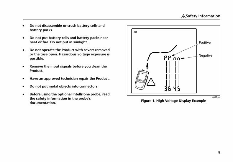
voltage polarities ( ) when it detects high voltage. Disconnect the tester if and appear. Figures 1 and 11 show examples of this display.
Do not use the Product around explosive gas, vapor, or in damp or wet environments.
Use this Product indoors only.
Do not connect the Product to voltages that are higher than the maximum voltage rating for the Product.
For Products that have multiple connectors for different types of tests on copper cabling, disconnect unused test leads from the connectors before you do a test.
Use the Product only as specified, or the protection supplied by the Product can be compromised.
Do not use and disable the Product if it is damaged.
Do not use the Product if it operates incorrectly.
Batteries contain hazardous chemicals that can cause burns or explode. If exposure to chemicals occurs, clean with water and get medical aid.
Remove the batteries if the Product is not used for an extended period of time, or if stored in temperatures above 50 °C. If the batteries are not removed, battery leakage can damage the Product.
The battery door must be closed and locked before you operate the Product.
Repair the Product before use if the battery leaks.
Replace the batteries when the low battery indicator shows to prevent incorrect measurements. (see "Battery Life, Status, and Replacement" on page 40)
Turn off the Product and disconnect all test leads, patch cords, and cables before you replace the battery.
Be sure that the battery polarity is correct to prevent battery leakage.
4
Safety Information
Do not disassemble or crush battery cells and battery packs.
Do not put battery cells and battery packs near heat or fire. Do not put in sunlight.
Do not operate the Product with covers removed or the case open. Hazardous voltage exposure is possible.
Remove the input signals before you clean the Product.
Have an approved technician repair the Product.
Do not put metal objects into connectors.
Before using the optional IntelliTone probe, read the safety information in the probe’s documentation.
egk29.eps
Figure 1. High Voltage Display Example
Positive
Negative
5

MicroScanner2 Cable VerifierUsers Manual
MicroScanner2 Features
egk01.eps
Figure 2. MicroScanner2 Features
6
MicroScanner2 Features
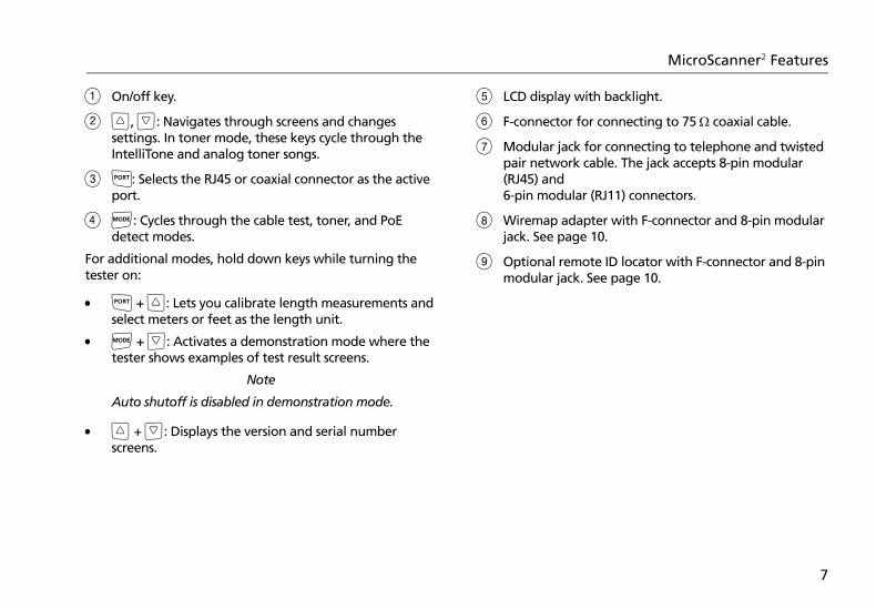
On/off key.
, : Navigates through screens and changes settings. In toner mode, these keys cycle through the IntelliTone and analog toner songs.
: Selects the RJ45 or coaxial connector as the active port.
: Cycles through the cable test, toner, and PoE detect modes.
For additional modes, hold down keys while turning the tester on:
+ : Lets you calibrate length measurements and select meters or feet as the length unit.
+ : Activates a demonstration mode where the tester shows examples of test result screens.
Note
Auto shutoff is disabled in demonstration mode.
+ : Displays the version and serial number screens.
LCD display with backlight.
F-connector for connecting to 75 coaxial cable.
Modular jack for connecting to telephone and twisted pair network cable. The jack accepts 8-pin modular (RJ45) and 6-pin modular (RJ11) connectors.
Wiremap adapter with F-connector and 8-pin modular jack. See page 10.
Optional remote ID locator with F-connector and 8-pin modular jack. See page 10.
7

MicroScanner2 Cable VerifierUsers Manual
Display Features
egk02.eps
Figure 3. Display Features
Tester icon
Detail screen indicator. See page 20.
Indicates which port is active, the RJ45 port () or the coaxial port ().
Tone mode indicator. See page 32.
Power over Ethernet mode indicator. See page 31.
Numeric display with feet/meters indicator.
Test activity indicator, which is animated when a test is running.
IntelliTone appears when the toner is in IntelliTone mode. See pages 32 and 36.
Indicates a short on the cable. See pages 13 and 30.
Telephone voltage indicator. See page 16.
Indicates a wiremap adapter is connected to the far end of the cable.
Low battery indicator. See page 40.
Indicates an ID locator is connected to the far end of the cable and shows the locator’s number.
Ethernet port indicator. See page 18.
O
P
8

Auto Shutoff
Wiremap diagram. For opens, the number of segments lit for the wire pair indicates the approximate distance to the fault. The rightmost segments indicate the shield. See pages 12 through 15.
The Indicates a fault or high voltage on the cable. SPLIT appears when the fault is a split pair. See page 15.
Auto ShutoffThe tester turns off after 10 minutes if no keys are pressed and nothing changes at the tester’s connectors.
Note
Auto shutoff is disabled in toner and demonstration modes.
Changing the Length Units1 Hold down and while turning on the tester.
2 Press to switch between meters and feet.
3 Turn the tester off then on to return to testing mode.
9

MicroScanner2 Cable VerifierUsers Manual
Using the Wiremap Adapter and Remote ID LocatorsTerminating twisted pair cabling with the standard wiremap adapter or optional remote ID locators lets the tester detect all types of wiremap faults. Without this termination, the tester cannot detect crossed wires or crossed pairs. For a wire pair with one wire open, termination is required to detect which wire is open. Without termination, the tester shows both wires as open.
Using multiple remote ID locators helps you identify connections at patch panels. The tester shows the number of the locator connected to the far end of the cabling, as shown on page 23.
To connect a remote ID locator to a modular (RJ) jack in a confined area or to a 4-pin modular jack (RJ11), use the optional universal adapter and a patch cord, as shown in Figure 4.
egk15.eps
Figure 4. Connecting a Remote ID Locator in a Confined Area or to an RJ11 Jack
Universal adapter(8-pin and 4-pin)
Remote ID locator
8-pin or 4-pin modular patch
cord
10

Testing Twisted Pair Cabling
Testing Twisted Pair Cabling1 Turn on the tester.
If the tester is already on and in coaxial test mode (), press to switch to twisted pair test mode ().
2 Connect the tester and wiremap adapter or ID locator to the cabling as shown in Figures 5 through 17.
The test runs continuously until you change modes or turn the tester off.
Notes
You can measure length without connecting a far end adapter; however, an adapter is required for a complete wiremap test.
If the PoE indicator appears, see page 31.
egk03.eps
Figure 5. Connecting to Twisted Pair Network Cabling
Wiremap adapter
Patch panel
RJ45 patch cords
Wall outlet
11
MicroScanner2 Cable VerifierUsers Manual
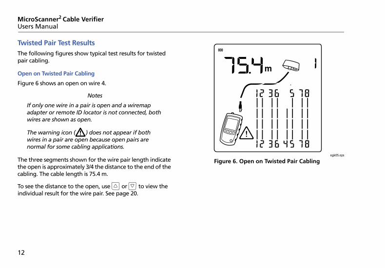
Twisted Pair Test ResultsThe following figures show typical test results for twisted pair cabling.
Open on Twisted Pair Cabling
Figure 6 shows an open on wire 4.
Notes
If only one wire in a pair is open and a wiremap adapter or remote ID locator is not connected, both wires are shown as open.
The warning icon () does not appear if both wires in a pair are open because open pairs are normal for some cabling applications.
The three segments shown for the wire pair length indicate the open is approximately 3/4 the distance to the end of the cabling. The cable length is 75.4 m.
To see the distance to the open, use or to view the individual result for the wire pair. See page 20.
egk05.eps
Figure 6. Open on Twisted Pair Cabling
12

Testing Twisted Pair Cabling
Short on Twisted Pair Cabling
Figure 7 shows a short between wires 5 and 6. The shorted wires flash to indicate the fault. The cable length is 75.4 m.
Note
When there is a short, the far-end adapter and the mapping of the unshorted wires are not shown.
ekg06.eps
Figure 7. Short on Twisted Pair Cabling
Crossed Wires
Figure 8 shows that wires 3 and 4 are crossed. The the pin numbers flash to indicate the fault. Cable length is 53.9 m. The cable is shielded.
Detection of crossed wires requires a far-end adapter.
egk08.eps
Figure 8. Crossed Wires
“Short” icon
Shield indicator
13

MicroScanner2 Cable VerifierUsers Manual
Crossed Pairs
Figure 9 shows that pairs 1,2 and 3,6 are crossed. The pin numbers flash to indicate the fault. This crossed pair is likely caused by mixing 568A and 568B cabling.
Detection of crossed pairs requires a far-end adapter.
egk09.eps
Figure 9. Crossed Pairs
14

Testing Twisted Pair Cabling
Split Pair
Figure 10 shows a split pair on 3,6 and 4,5. The split pair flashes to indicate the fault. The cable length is 75.4 m.
In a split pair, continuity from end to end is correct, but is made with wires from different pairs. Split pairs cause excessive crosstalk that interferes with network operation.
Note
Cables with untwisted pairs, such as telephone cords, typically show split pairs due to excessive crosstalk.
egk10.eps
Figure 10. Split Pair
Split pair icon The split
pair flashes
Split pair wiring
15

MicroScanner2 Cable VerifierUsers Manual
Telephone Voltages Detected
Figure 11 shows that telephone voltage is detected on pair 4,5.
Length is not shown because the voltage interferes with length measurements.
WarningThe tester is not intended to be connected to active telephone inputs, systems, or equipment, including ISDN devices. Prolonged exposure to the voltages applied by these interfaces may damage the tester. Disconnect the tester if and appear.
egk11.eps
Figure 11. Telephone Voltages Detected
Telephone voltage icon
Positive wire (tip)
Negative wire (ring)
16

Testing Twisted Pair Cabling
Bridge Tap Detected
Figure 12 shows a bridge tap detected at about 53.2 m. Only the first bridge tap detected is reported. The distance to a bridge tap is approximate because multiple reflections from the bridge tap interfere with length measurements.
Note
Bridge taps more than 328 ft (100 m) from the tester or taps less than 16 ft (5 m) long may not be detected.
egk12.eps
Figure 12. Bridge Tap Detected
17
MicroScanner2 Cable VerifierUsers Manual
Ethernet Port Detected
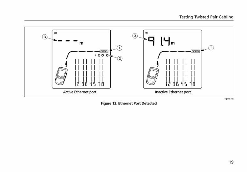
The tester can detect active and inactive Ethernet ports, as shown in Figure 13.
Ethernet port icon.
Port speed for an active 1000 megabit port. The speeds are 10, 100, or 1000 megabits per second. The example shows 1000 megabits per second. If the port supports multiple speeds the number cycles through the speeds.
Cable length. Dashes are shown if the tester cannot measure the length. This can occur if the port does not produce reflections.
Length may fluctuate or be obviously too high if the port’s impedance fluctuates or varies from the cable’s impedance. When in doubt, disconnect the cable from the port to get an accurate length measurement.
18
Testing Twisted Pair Cabling
egk13.eps
Figure 13. Ethernet Port Detected
A
B
C C
A
Active Ethernet port Inactive Ethernet port
19
MicroScanner2 Cable VerifierUsers Manual
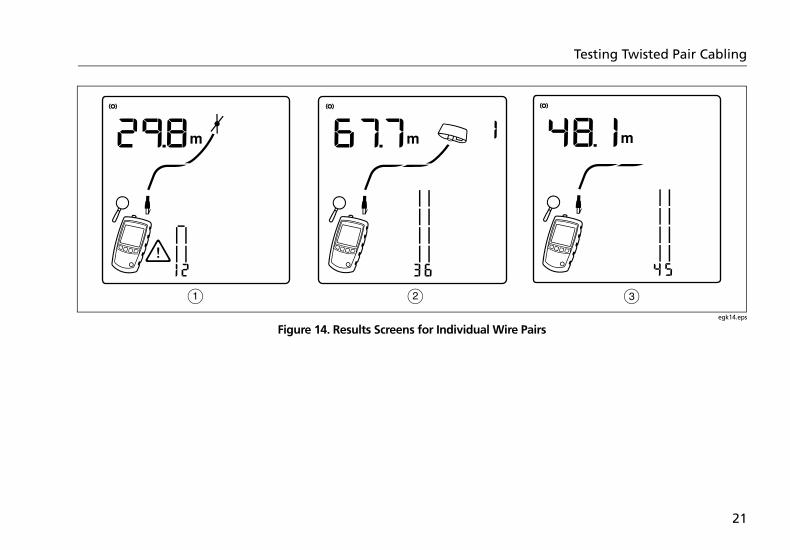
Viewing Individual ResultsTo see individual results for each wire pair, use or ; to move among the screens.
In this mode, the tester continuously tests only the wire pair you are viewing.
Figure 14 shows examples of these screens.
Short on pair 1,2 at 29.8 m.
Notes
On the individual results screens, shorts are shown only when they are between wires in a pair.
When there is a short, the far-end adapter and the mapping of the unshorted wires are not shown.
Pair 3,6 is 67.7 m long and is terminated with the wiremap adapter.
Open on pair 4,5 at 48.1 m. The open could be on one or both wires.
20
Testing Twisted Pair Cabling
egk14.eps
Figure 14. Results Screens for Individual Wire Pairs
21

MicroScanner2 Cable VerifierUsers Manual
Using Multiple Remote ID LocatorsUsing multiple remote ID locators helps you identify multiple network connections at a patch panel, as shown in Figure 15.
The display in Figure 15 shows that the tester is connected to the cable terminated with remote ID locator number 3.
Caution
Do not use multiple far end adapters in star or bus topologies. Doing so causes incorrect wiremap results.
22

Testing Twisted Pair Cabling
egk04.eps
Figure 15. Using Multiple Remote ID Locators
Patch panel
Locator # 2Locator # 3
Locator # 4
Locator # 5
Remote ID locators connected to wall
outlets
23
MicroScanner2 Cable VerifierUsers Manual
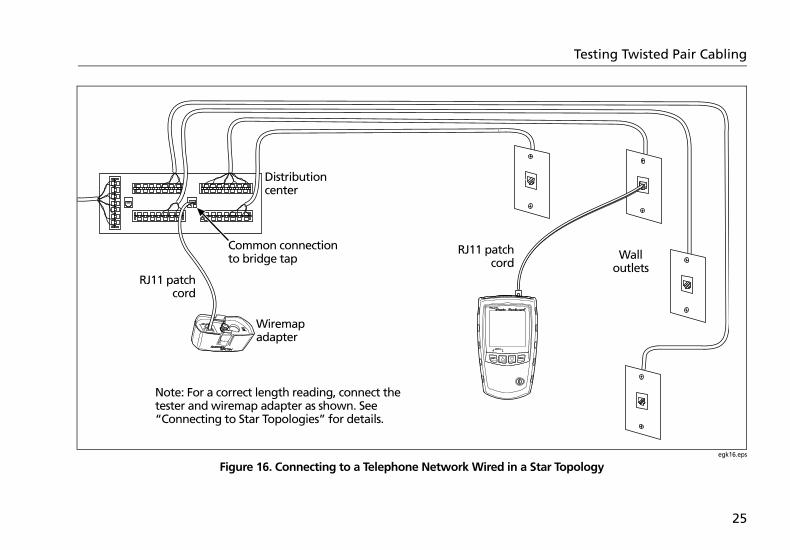
Connecting to Telephone Networks Wired in Star TopologiesTelephone cables wired in a star topology (Figure 16) are connected together at a bridge tap at the distribution center. The bridge tap connects each wire to all other wires of the same number.
The tester detects bridge taps and measures the distance to the bridge tap. To measure the length of each cable connected to the bridge tap, connect the wiremap adapter or remote ID locator to the bridge tap and the tester to the wall outlet.
The tester cannot measure length past the bridge tap because reflections from the bridge tap connections interfere with measurements.
If you connect the tester to the bridge tap, the tester measures the length only to the bridge tap, which is only the patch cord length.
Caution
Do not use multiple far end adapters in star or bus topologies. Doing so causes incorrect wiremap results.
24
Testing Twisted Pair Cabling
egk16.eps
Figure 16. Connecting to a Telephone Network Wired in a Star Topology
Distribution center
Common connection to bridge tap
Wiremap adapter
RJ11 patchcord
Wall outlets
Note: For a correct length reading, connect the tester and wiremap adapter as shown. See “Connecting to Star Topologies” for details.
RJ11 patchcord
25

MicroScanner2 Cable VerifierUsers Manual
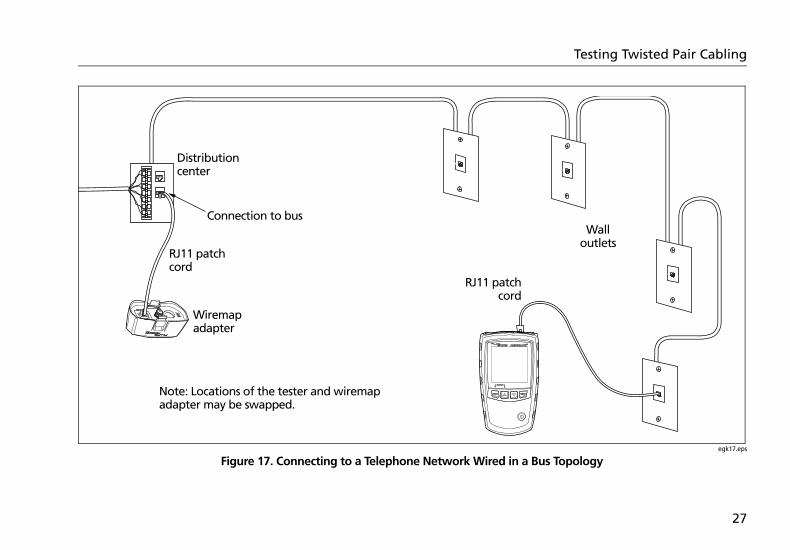
Connecting to Telephone Networks Wired in Bus TopologiesTelephone cables wired in a bus topology (Figure 17) connect the wall outlets in series. In this topology, you measure the length from the last outlet to the wiremap adapter.
If you connect to an outlet in the middle of the series, the tester reports a bridge tap. The length reported is the length to the outlet, which is the patch cord length. The tester cannot measure length past the outlet because reflections from the cables on either side interfere with measurements.
If you are unsure which outlet is the last in the bus, do the following:
1 Connect the wiremap adapter or ID locator to the beginning of the bus at the distribution center.
2 Connect the tester to an outlet and run the twisted pair cable test.
If the tester reports a bridge tap, move to another outlet. The last outlet will not show a bridge tap, and will show the length to the distribution center.
Caution
Do not use multiple far end adapters in star or bus topologies. Doing so causes incorrect wiremap results.
26
Testing Twisted Pair Cabling
egk17.eps
Figure 17. Connecting to a Telephone Network Wired in a Bus Topology
Distribution center
Connection to bus
Wiremap adapter
RJ11 patch cord
Wall outlets
Note: Locations of the tester and wiremap adapter may be swapped.
RJ11 patchcord
27
MicroScanner2 Cable VerifierUsers Manual
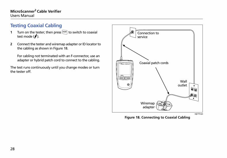
Testing Coaxial Cabling1 Turn on the tester; then press to switch to coaxial
test mode ().
2 Connect the tester and wiremap adapter or ID locator to the cabling as shown in Figure 18.
For cabling not terminated with an F-connector, use an adapter or hybrid patch cord to connect to the cabling.
The test runs continuously until you change modes or turn the tester off.
egk19.eps
Figure 18. Connecting to Coaxial Cabling
Connection to service
Coaxial patch cords
Wiremapadapter
Walloutlet
28
Testing Coaxial Cabling
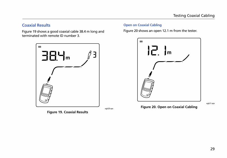
Coaxial ResultsFigure 19 shows a good coaxial cable 38.4 m long and terminated with remote ID number 3.
egk20.eps
Figure 19. Coaxial Results
Open on Coaxial Cabling
Figure 20 shows an open 12.1 m from the tester.
egk21.eps
Figure 20. Open on Coaxial Cabling
29

MicroScanner2 Cable VerifierUsers Manual
Short on Coaxial Cabling
Figure 21 shows a short 12.1 m from the tester.
egk22.eps
Figure 21. Short on Coaxial Cabling
Unknown Termination on Coaxial Cabling
Figure 22 shows a cable connected to a device at the far end, such as a television, CATV service, VCR, DVD player, satellite dish, splitter, or antenna. Dashes shown for length mean the tester cannot measure length because the device does not produce reflections.
egk23.eps
Figure 22. Unknown Termination on Coaxial Cabling
30
Detecting Power Over Ethernet
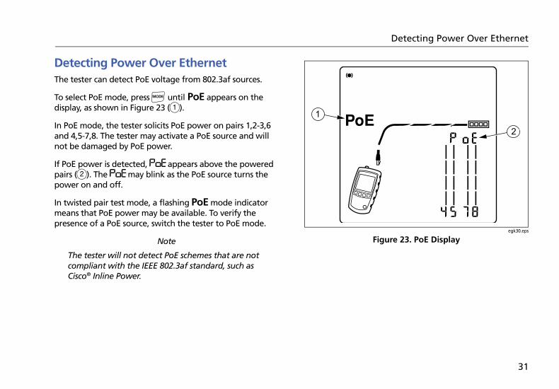
Detecting Power Over EthernetThe tester can detect PoE voltage from 802.3af sources.
To select PoE mode, press until PoE appears on the display, as shown in Figure 23 ().
In PoE mode, the tester solicits PoE power on pairs 1,2-3,6 and 4,5-7,8. The tester may activate a PoE source and will not be damaged by PoE power.
If PoE power is detected, appears above the powered pairs (). The may blink as the PoE source turns the power on and off.
In twisted pair test mode, a flashing PoE mode indicator means that PoE power may be available. To verify the presence of a PoE source, switch the tester to PoE mode.
Note
The tester will not detect PoE schemes that are not compliant with the IEEE 802.3af standard, such as Cisco® Inline Power.
egk30.eps
Figure 23. PoE Display
31

MicroScanner2 Cable VerifierUsers Manual
Using the TonerYou can use the tester with an optional tone probe to locate cables in bundles, at patch panels, or behind walls.
Use the tester’s IntelliTone™ mode with an optional Fluke Networks IP100 or IP200 tone probe. The digital IntelliTone signal is easier to detect at a distance than analog tones, and its frequency and encoding eliminate cable misidentification due to signal bleed and radiated or ambient noise.
The tester’s analog tone mode is compatible with most tone probes.
The analog tone mode features the SmartTone™ function for positive identification of cables in bundles.
Toning in IntelliTone Mode (optional IntelliTone probe required)Refer to Figures 24 and 25.
1 Connect the tester to the cable.
2 Press to select twisted pair () or coaxial () cable.
3 Press until , IntelliTone, and and a scrolling pattern of 1s and 0s appear on the display (, , and in Figure 24).
4 To toggle between the two IntelliTone songs press then . The display shows the song number ().
If you press or repeatedly, the tester cycles through the IntelliTone and analog songs.
5 Turn the probe’s rotary switch to (locate).
6 Use the probe to find the general location of the tone at a cable rack, patch panel, or behind a wall, as shown in Figure 25. The SYNC LED lights up green when the probe is receiving the IntelliTone signal.
The probe’s LEDs light up from 1 to 8 as the signal strength increases. The higher the number, the stronger the signal.
32

Using the Toner
Notes
If you cannot locate the IntelliTone signal on 2-conductor cables, the cable may be shorted. Use the tester to check for shorts. See pages 11 and 13.
7 Turn the probe’s rotary switch to (isolate).
8 Use the probe to isolate the tone source in the cable bundle or at the patch panel. The SYNC LED lights up green when the probe is receiving the IntelliTone signal.
The probe’s LEDs light up from 1 to 8 as the signal strength increases. The higher the number, the stronger the signal.
egk07.eps
Figure 24. IntelliTone Toner Mode Display
33
MicroScanner2 Cable VerifierUsers Manual
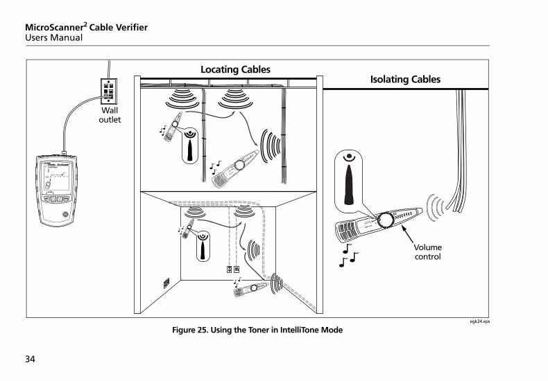
egk24.eps
Figure 25. Using the Toner in IntelliTone Mode
Locating Cables
Volume control
Wall outlet
Isolating Cables
34

Using the Toner
Analog Toner Mode (optional tone probe required)Refer to Figure 26.
1 Connect the tester to the cable.
2 Press to select twisted pair or coaxial cable.
3 Press until appears on the display (); then press to enter analog toner mode. The display shows a scrolling sinewave in analog toner mode ().
4 To change songs, press . The display shows the song number (). The analog toner has four songs.
If you press or repeatedly, the tester cycles through the analog and IntelliTone songs.
5 Use the probe to search for the cable.
egk25.eps
Figure 26. Analog Toner Mode Display
A
B
C
35

MicroScanner2 Cable VerifierUsers Manual
Using the SmartTone FunctionUse the SmartTone™ function when you have trouble locating a cable. This function changes the toner’s song when you short a wire pair in the cable connected to the tester. SmartTone works with the IntelliTone probe and with analog probes.
Note
Use the SmartTone function only on dry pairs of wires that are unterminated at both ends. Do not use this function on powered wires.
1 Press to select twisted pair or coaxial cabling.
2 Press until appears on the display.
3 Press to select the analog toner mode (IntelliTone disappears from the display).
4 At the far end of the cabling, place the probe near the ends of the cables.
5 Momentarily short a wire pair in a cable (twisted pair) or short the conductor and shield in a cable (coaxial). If the song changes when you release the short, you have found the cable connected to the tester.
Using the IntelliTone Cable Map Function (optional IP200 probe required)The tester’s IntelliTone function works with an optional IP200 probe’s cable map function to verify wiring at the far end of the cabling. The probe’s cable map function identifies the most common wiring faults on twisted pair cabling: shorts, opens, and crossed pairs.
1 Press to select twisted pair cabling ().
2 Turn the probe’s rotary switch to CABLE MAP.
3 Connect the tester and probe to the cabling as shown in Figure 27.
4 Press until appears on the display. IntelliTone mode is indicated by IntelliTone and a scrolling pattern of 1s and 0s on the display. See Figure 27.
5 The probe’s LEDs light in sequence to indicate the cable’s wiring. See the probe’s documentation for details.
36

Using the IntelliTone Cable Map Function (optional IP200 probe required)
Note
Normally, the probe’s SYNC LED lights to indicate reception of the IntelliTone signal. You may change the LED’s function to indicate shield continuity. See the probe’s documentation for details.
egk26.eps
Figure 27. Using the Toner with the IP200 IntelliTone Cable Map Function
LEDs show the wiremap. See the IntelliTone manual for details.
37

MicroScanner2 Cable VerifierUsers Manual
Calibrating Length MeasurementsThe tester uses an NVP value (nominal velocity of propagation) and the signal delay through the cable to calculate length. The tester’s default NVP values are usually accurate enough to verify length; however, you can increase the accuracy of length measurements by adjusting the NVP to a specified or actual value.
The default NVP values are 70 % for twisted pair cable and 82 % for coaxial cable.
Note
NVP values can vary among cable types, lots, and manufacturers. In most cases, these differences are minor and may be disregarded.
Setting the NVP to a Specified ValueTo enter the NVP value specified by the manufacturer:
1 Turn on the tester while holding down the and keys.
2 To set the NVP for the coaxial port (), press .
3 Use and to set the NVP value.
4 To save the setting and exit NVP mode, turn the tester off then on again.
Determining a Cable’s Actual NVPYou can determine a cable’s actual NVP by adjusting the measured length to match a known length of cable.
To determine a cable’s NVP:
1 Turn on the tester while holding down the and keys.
2 To set the NVP for the coaxial port (), press .
3 Connect a known length of the cable to be tested to the tester’s twisted pair or coaxial connector.
38
Maintenance
Notes
The cable must be at least 49 ft (15 m) long. If the cable is too short, “---” appears for the length.
For the best accuracy, use a cable between 49 ft (15 m) and 98 ft (30 m) long.
The cable must not be connected to anything.
4 To switch between meters and feet, press .
5 Use and to change the NVP until the measured length matches the actual length of the cable.
6 To save the setting and exit NVP mode, turn the tester off then on again.
Maintenance
WarningTo avoid possible fire, electric shock, personal injury, or damage to the tester:
Do not open the case. No user-serviceable parts are inside.
Replacing electrical parts yourself will void the tester’s warranty and might compromise its safety features.
Use only specified replacement parts for user-replaceable items.
Use only Fluke Networks authorized service centers.
39

MicroScanner2 Cable VerifierUsers Manual
CleaningClean the display with glass cleaner and a soft, lint-free cloth. Clean the case with a soft cloth dampened with water or water and a mild soap.
Caution
To avoid damaging the display or the case, do not use solvents or abrasive cleansers.
Battery Life, Status, and Replacement
WarningTo avoid possible electric shock or personal injury:
Turn off the tester and disconnect all test leads before replacing the battery.
Use only the correct type of batteries, properly installed in the case, to power the tester.
The batteries last for about 20 hours of typical use.
Replace the tester’s batteries when the low battery indicator ( ) appears. See Figure 28.
You can use the following types of AA (IEC LR6) batteries in the tester:
Alkaline
Lithium
Rechargeable nickel-metal hydride (NiMH)
Rechargeable nickel-cadmium batteries (NiCD)
egk28.eps
Figure 28. Replacing the Tester’s Batteries
40

If Something Seems Wrong
Checking the Tester’s Version and Serial NumberTurn the tester on while holding down the and keys.
Use and to scroll through the screens:
: Software version
: Serial number
: Factory test date
To exit this mode, turn the tester off.
If Something Seems WrongIf something seems wrong with the tester, refer to Table 2.
If Table 2 does not help you solve a problem with the tester, contact Fluke Networks for additional help. If possible, have the tester’s version and serial number.
For warranty information, refer to the warranty at the beginning of this manual. If the warranty has lapsed, contact Fluke Networks for repair prices.
Table 2. Troubleshooting the Tester
Symptom Action
The keypad does not respond. Press and hold until the tester turns off; then turn the tester on again.
The tester will not turn on. Replace the batteries, verifying that they are installed correctly. See Figure 28 on page 40.
Length measurements are incorrect. Check the NVP value. See “Calibrating Length Measurements” on page 38.
41

MicroScanner2 Cable VerifierUsers Manual
Options and AccessoriesSee Table 3.
For the latest list of options and accessories visit the Fluke Networks website at www.flukenetworks.com.
Table 3. Options and Accessories
Option or Accessory Fluke Networks Model Number
Remote ID Locator Kit, numbers 2-7 MS2-IDK27
Wiremap adapter MS2-WM
Test lead, 8-pin modular plug (RJ45) to 8 alligator clips CLIP-SET
Coaxial Adapter Kit (F-connector barrel adapter, female-to-female BNC adapter, female-to-female RCA adapter)
CIQ-COAX
Universal adapter, 8-pin/4-pin modular jack to 8-pin/4-pin modular jack CIQ-RJA
Carrying case for MicroScanner2 Professional kit MS2-CPK
Carrying pouch for MicroScanner2 tester MS2-POUCH
42

Specifications
SpecificationsSpecifications apply at 23 oC (73 oF), unless otherwise noted.
Environmental Specifications
Operating temperature 32 °F to 113 °F (0 oC to 45 oC)
Storage temperature -4 °F to +140 °F (-20 oC to +60 oC)
Operating relative humidity(% RH without condensation)
90 % (50 °F to 95 °F; 10 oC to 35 oC)75 % (95 °F to 113 °F; 35 oC to 45 oC)
Shock and Vibration Random, 2 g, 5 Hz-500 Hz (Class 2)1 m drop test with and without wiremap adapter attached
Safety IEC 61010-1 3rd Edition
Altitude 4,000 m; Storage: 12,000 m
EMC IEC 61326-1
43

MicroScanner2 Cable VerifierUsers Manual
General Specifications
Test Modes
Test connectors Shielded 8-pin modular jack accepts 8-pin modular (RJ45) and 4-pin modular (RJ11) plugs.F-connector for coaxial cable.
Power Battery type: 2 AA (NEDA 15A, IEC LR6) alkaline batteriesBattery life: 20 hours of typical useOther compatible battery types: 2 AA photo lithium, NIMH, NICAD
Dimensions and weight(with batteries installed and wiremap adapter attached
3 in x 6.4” x 1.4 in (7.6 cm x 16.3 cm x 3.6 cm)0.8 lb (0.36 kg)
Display Monochrome LCD with backlight
Cable test Measures length, verifies wiremap, identifies remote ID locators, and detects Ethernet ports. Displays results on one screen.
Tone Generates Intellitone™ and normal analog toning signals
PoE Solicits and detects the presence of 802.3af compatible PoE (Power over Ethernet) devices
44
Specifications
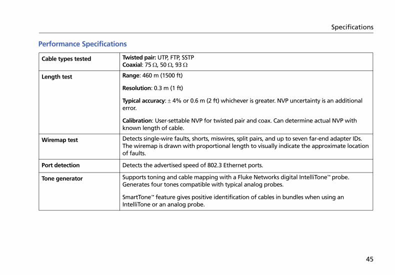
Performance Specifications
Cable types tested Twisted pair: UTP, FTP, SSTPCoaxial: 75 , 50 , 93
Length test Range: 460 m (1500 ft)
Resolution: 0.3 m (1 ft)
Typical accuracy: 4% or 0.6 m (2 ft) whichever is greater. NVP uncertainty is an additional error.
Calibration: User-settable NVP for twisted pair and coax. Can determine actual NVP with known length of cable.
Wiremap test Detects single-wire faults, shorts, miswires, split pairs, and up to seven far-end adapter IDs. The wiremap is drawn with proportional length to visually indicate the approximate location of faults.
Port detection Detects the advertised speed of 802.3 Ethernet ports.
Tone generator Supports toning and cable mapping with a Fluke Networks digital IntelliTone™ probe. Generates four tones compatible with typical analog probes.
SmartTone™ feature gives positive identification of cables in bundles when using an IntelliTone or an analog probe.
45

MicroScanner2 Cable VerifierUsers Manual
Regulatory InformationThis equipment generates, uses, and can radiate radio frequency energy, and, if not installed and used in accordance with the manual, may cause interference to radio communications. It has been tested and found to comply with the limits for a Class A digital device pursuant to Part 15, Subpart J of the FCC rules, which are designed to provide reasonable protection against such interference when operated in a commercial environment. Operation of the equipment in a residential area is likely to cause interference, in which case the user, at his own expense, will be required to take whatever measures may be required to correct the interference.
46

Appendix A: Diagnosing Wiremap Faults
Appendix A lists the typical causes of wiremap failures.
Open Wires connected to wrong pins at connector or
punchdown blocks
Faulty connections
Damaged connector
Damaged cable
Wrong pairs selected in setup
Wrong application for cable
Split PairWires connected to wrong pins at connector or punchdown block.
Reversed PairsWires connected to wrong pins at connector or punchdown block.
Crossed Pairs Wires connected to wrong pins at connector or
punchdown block.
Mix of 568A and 568B wiring standards (12 and 36 crossed).
Crossover cables used where not needed (12 and 36 crossed).
47

MicroScanner2 Cable VerifierUsers Manual
Short Damaged connector
Damaged cable
Conductive material stuck between pins at connector.
Improper connector termination
Wrong application for cable
48

Index
Symbols"?" on coaxial screen, 30
–A–accessories, 42analog toner, 35auto shutoff, 9
–B–batteries, 40bridge tap, 17bus topology, 26
–C–cable map function, 36
cable testscoaxial cabling, 28twisted pair, 11
cleaning, 40coaxial
connections, 28open, 29, 30short, 30unknown termination, 30
connectionscoaxial, 28twisted pair, 11
connectors, 7crossed pairs, 14crossed wires, 13
49
MicroScanner2 Cable VerifierUsers Manual
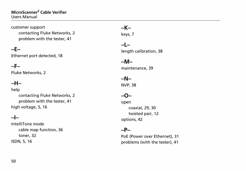
customer supportcontacting Fluke Networks, 2problem with the tester, 41
–E–Ethernet port detected, 18
–F–Fluke Networks, 2
–H–help
contacting Fluke Networks, 2problem with the tester, 41
high voltage, 5, 16
–I–IntelliTone mode
cable map function, 36toner, 32
ISDN, 5, 16
–K–keys, 7
–L–length calibration, 38
–M–maintenance, 39
–N–NVP, 38
–O–open
coaxial, 29, 30twisted pair, 12
options, 42
–P–PoE (Power over Ethernet), 31problems (with the tester), 41
50

Index
–R–registration, 1remote ID locator, 10, 22replacement parts, 42RJ11 jack, 10
–S–safety information, 3, 39serial number, 41service, 41short
coaxial, 30twisted pair, 13
SmartTone function, 35, 36specifications, 43split pair, 15star topology, 24, 27symbols, 2
–T–telephone cord (split pair), 15telephone voltages, 5, 16
testingcoaxial cabling, 28twisted pair cabling, 11
toner, 32analog mode, 35IntelliTone mode, 32SmartTone function, 35, 36
troubleshootingcabling faults, 47the tester, 41
twisted pairbridge tap, 17connections
bus topology, 26network cabling, 11star topology, 24, 27
crossed pairs, 14crossed wires, 13individual results, 20open, 12PoE detection, 18short, 13
51

MicroScanner2 Cable VerifierUsers Manual
split pair, 15telephone voltages, 16
–U–universal adapter, 10
–V–version information, 41voltage detection, 5, 16
–W–wiremap adapter, 10
52


![LLVM MC in Practice · 2019. 10. 30. · _fac: push {r4, r7, lr} ldr! r0, [pc, #20] mov r1, #1 add r7, sp, #4 ldr! r0, [pc, r0] mov! r2, r1 ldr! r0, [r0] b! #0 # 4 bytes of data:.long](https://static.documents.pub/doc/80x56/60c63395503ad85a6a26c0e3/llvm-mc-in-practice-2019-10-30-fac-push-r4-r7-lr-ldr-r0-pc-20-mov.jpg)


