Page 1
© 2017 Cisco and/or its affiliates. All rights reserved. This document is Cisco Public Information. Page 1 of 38
White Paper
Manage Hybrid Clouds with a Cisco CloudCenter, Cisco
Application Centric Infrastructure, and Cisco UCS Director Solution
Page 2
© 2017 Cisco and/or its affiliates. All rights reserved. This document is Cisco Public Information. Page 2 of 38
Contents
Overview ................................................................................................................................................................... 3 What Is Cisco ACI? ............................................................................................................................................... 3 What Is Cisco CloudCenter? ................................................................................................................................. 3 What Is Cisco UCS Director? ................................................................................................................................ 5
Private and Hybrid Cloud Requirements ............................................................................................................... 5 Main Features of the Cisco Solution Suite ............................................................................................................ 6
Reference Design .................................................................................................................................................... 7 Topology ............................................................................................................................................................... 7 Reference Architecture Components .................................................................................................................... 8 Network Topology ............................................................................................................................................... 10 Day-1 Administration Workflow ........................................................................................................................... 10
Prerequisites .................................................................................................................................................. 10 Summary of Cisco UCS Director Workflows .................................................................................................. 11
Cisco CloudCenter Setup and Integration with Cisco ACI .................................................................................. 12 Clouds ............................................................................................................................................................ 12 Cloud Accounts .............................................................................................................................................. 13 Regions .......................................................................................................................................................... 14 Extensions ...................................................................................................................................................... 15 Deployment Environment ............................................................................................................................... 16 Application Profile Creation and Application Deployment ............................................................................... 19
IP Address Management ....................................................................................................................................... 20 Static Provisioning .............................................................................................................................................. 20 DHCP Provisioning ............................................................................................................................................. 23
F5 Load-Balancer Integration ............................................................................................................................... 24
Conclusion ............................................................................................................................................................. 27
For More Information ............................................................................................................................................. 28
Appendix: Cisco UCS Director Workflows .......................................................................................................... 28 Bare-Metal Startup and Association with VMware vCenter ................................................................................. 28 Cisco ACI Pre-Provisioning ................................................................................................................................. 29 Infoblox Provisioning and Integration with Cisco ACI .......................................................................................... 35 F5 Provisioning ................................................................................................................................................... 37
Page 3
© 2017 Cisco and/or its affiliates. All rights reserved. This document is Cisco Public Information. Page 3 of 38
Overview
This document provides an approach to building a cohesive hybrid cloud solution using a suite of Cisco®
technologies including Cisco CloudCenter™
(formerly CliQr CloudCenter), Cisco Application Centric Infrastructure
(Cisco ACI™
), and Cisco UCS® Director products.
What Is Cisco ACI?
With Cisco ACI, data center infrastructure is deployed, monitored, and managed fundamentally to meet the needs
of ever-changing application requirements. Cisco ACI reduces complexity by abstracting much of the networking
infrastructure and implementing a policy-based framework based on the needs of the application, helping the data
center adapt in ways that address the revenue goals of the business.
Cisco ACI works to solve the business problem of slow application deployment due to manual, error-prone
technical network provisioning and change management by enabling rapid deployment of applications to meet
changing business demands. It delivers an integrated approach by providing application-centric, end-to-end
visibility from the software overlay to the physical switching infrastructure. It also accelerates and optimizes Layer 4
through Layer 7 (L4-L7) service insertion to build a system that brings the language of applications to the network,
automated all the way up the stack.
Cisco ACI delivers automation, programmability, and centralized provisioning by allowing the network to be
automated and configured based on business-level application requirements. It supports accelerated, cohesive
deployment of applications across network and L4-L7 infrastructure and provides visibility and management at the
application level. Advanced telemetry for visibility into network health, and simplified day-2 operations also
enhance troubleshooting of the application itself. The diverse and open Cisco ACI ecosystem allows organizations
to work with any upper- or lower-level management or orchestration system and attracts a broad community of
developers through an open, representational state transfer (REST) API. Through integration and automation of
both Cisco and third-party L4-L7 virtual and physical service devices, organizations can use a single tool to
manage the entire application environment.
With Cisco ACI, customers can deploy the network based on application requirements in the form of policies,
removing the need to translate the complexity of current network constraints. Cisco ACI also helps organizations
ensure security and performance while maintaining complete visibility into application health for both virtual and
physical resources.
What Is Cisco CloudCenter?
Cisco CloudCenter is a centralized self-service application portal that securely provisions infrastructure resources
and deploys applications across more than 19 data center, private, and public cloud environments. Cisco
CloudCenter improves IT speed and agility while also reducing complexity by separating and optimizing workloads
for users, who can quickly and easily model, deploy, and manage applications in any environment, and for
administrators, who get visibility and governance control across boundaries of applications, clouds, and users.
Cisco CloudCenter provides a single-platform solution with unique application-centric technology that abstracts the
application from the underlying cloud environment and helps ensure that the infrastructure adapts to meet the
deployment and management needs of each application. Users no longer have to deal with cloud-specific APIs or
configuration. Cisco CloudCenter abstracts away the back-end infrastructure, making the application the focal point
of the user experience.
Page 4
© 2017 Cisco and/or its affiliates. All rights reserved. This document is Cisco Public Information. Page 4 of 38
With Cisco CloudCenter, enterprise IT organizations can migrate and manage applications starting with a single
application on a single cloud, or many applications on multiple clouds. Or organizations can use Cisco CloudCenter
to automate DevOps and continuous-delivery operations, provide dynamic capacity augmentation, or deliver IT as
a service (ITaaS).
The power of Cisco CloudCenter comes from its patented application-centric technology. The solution combines a
cloud-independent application profile, which defines deployment and management requirements for the application
stack. Cisco CloudCenter uses cloud-specific orchestrators that know how to talk to all the supported clouds on the
back end, which deploys both the infrastructure and the application using the best practices for each environment
without user knowledge of the clouds.
Cisco CloudCenter has three major components:
● Cisco CloudCenter Manager is a centralized management portal that allows users to quickly and easily
model, deploy, and manage applications. It gives administrators enterprise-class visibility and governance
control over applications, clouds, and users.
● Cisco CloudCenter Orchestrator is a cloud-specific, multitenant orchestration tier that is transparent to users
and is installed in each data center private cloud or public cloud environment. It securely deploys both the
infrastructure and the application, manages the deployment including run-time policies, and aggregates use
and cost information.
● The Cisco CloudCenter application profile is a user-created model of an application’s deployment and
management requirements in a portable format. Each application profile is easily created with a simple,
visual, drag-and-drop topology modeler using a library of predefined and customized services, images, and
containers.
As shown in Figure 1, Cisco CloudCenter users can create and deploy an application profile to the target cloud
environment. The cloud-specific, multitenant orchestrator natively deploys the application profile in a way that
optimizes security, increases application performance, and maintains application portability. By using cloud-specific
orchestrators, Cisco CloudCenter can abstract away the specifics of the configuration.
Figure 1. Cisco CloudCenter Components
Unlike cloud management solutions that aren’t centered on the needs of applications, Cisco CloudCenter does not
use cloud-specific scripting. It does not require any manual writing of orchestration workflows or modification of
application code. There is no cloud lock-in because Cisco CloudCenter is cloud independent. By using a single
platform, IT doesn’t need to invest in multiple cloud-specific management stacks and teams.
Page 5
© 2017 Cisco and/or its affiliates. All rights reserved. This document is Cisco Public Information. Page 5 of 38
What Is Cisco UCS Director?
Cisco UCS Director delivers unified provisioning and management across enterprises’ computing, network,
storage, and virtualization layers. It significantly accelerates the process of deploying new infrastructure and
launching applications.
Cisco UCS Director is a workflow-based tool that automates and orchestrates processes that implement an
organization’s best practices. It works transparently with a wide range of IT infrastructure, making it easy to
integrate with most enterprises’ existing infrastructure, both physical and virtual.
Cisco UCS Director provides:
● Single-pane infrastructure management: Through a single interface, you can automate and orchestrate IT
infrastructure, including computing, network, and storage infrastructure, with physical and virtual resources
treated equally. This holistic management approach makes provisioning and management processes
consistent and reliable.
● Policy-based infrastructure provisioning: Cisco UCS Director is role and policy based, so your subject-
matter experts can work together to define your policies one time. After the policies are created, any level of
administrator can use the policies to provision resources.
● End-to-end infrastructure process automation: Cisco UCS Director deploys solutions quickly and accurately,
orchestrating the steps to prepare the network, computing, and storage resources needed to support an
application. Deployment time is reduced, shortening time to revenue.
● Complete infrastructure lifecycle management: Cisco UCS Director implements your processes to deliver IT
infrastructure as a service (IaaS), monitor service operation, and decommission the service when it is no
longer required. This process helps you reclaim time and resources to make better use of your IT
investments.
Private and Hybrid Cloud Requirements
Enterprises today are migrating their virtualized and physical infrastructure to the cloud, using both private and
public clouds. In adopting cloud environments, enterprises are seeking to address use cases such as cloud
bursting, management of peak demand, the differing requirements for development and test applications and for
production applications, and the desire for full-fledged ITaaS to emulate all the use cases supported by public
clouds.
Enterprises that are building private and hybrid clouds require a suite of features to enable them to build and
manage the cloud, provide functions to users, and integrate with the enterprise’s systems and processes.
Private and hybrid cloud requirements include the following:
● Infrastructure lifecycle management for converged infrastructure: Lifecycle management is a basic and
important function of a cloud from the cloud administrator’s point of view. Administering clouds requires
transparently managing a large pool of servers and network and storage infrastructure resources and
enabling users to manage the lifecycles of their virtual machines and containers in the cloud.
● Self-service portal: A central management portal is essential from a cloud user’s point of view. This portal
offers features such as the following:
◦ User management, including user login through integration with enterprise single sign-on (SSO) protocols
(Security Assertion Markup Language [SAML], Lightweight Directory Access Protocol [LDAP], etc.), user
inventory, and metering
Page 6
© 2017 Cisco and/or its affiliates. All rights reserved. This document is Cisco Public Information. Page 6 of 38
◦ Image and application profile management, providing users with access to a wide range of virtual
machine and application templates and defining complex application profiles consisting of multiple
individual applications and the application’s networking and storage properties
◦ Lifecycle management of virtual instances
● Application provisioning, elastic scaling, quality of service (QoS), and security: These advanced features
require a tight coupling between the orchestrator and the underlying network and storage infrastructure. Use
cases include setup of automatic configuration of security and policy groups for applications, configuration
of load balancing for elastic scaling, and setup of multiple data stores with different storage service-level
agreements (SLAs) to provide user choice.
● Multicloud management: Multicloud management is becoming an important feature because of the
increased adoption of hybrid clouds and the use of multiple private cloud options. Users need a single pane
that abstracts the configuration of the underlying clouds to operate their virtual instances and applications
transparently and easily.
● Integration with enterprise systems and processes: Cloud resource utilization provisioning cannot be
automated effectively without including the enterprise approval processes, metering the use of resources,
and applying the enterprise’s cost accounting policies for the resources used. This feature is especially
important when public cloud resources are used. Enterprise policies are enforced through integration with
service catalog applications such as ServiceNow for automated approval workflow management, user quota
management, and IT service management.
Main Features of the Cisco Solution Suite
Cisco CloudCenter, Cisco UCS Director, Cisco UCS servers, and Cisco ACI fabric infrastructure together provide
enterprise IT with a solution suite to transparently integrate a private cloud stack and orchestrate multicloud, private
cloud, and hybrid cloud environments. The main features include the following:
● Converged infrastructure lifecycle management: The Cisco CloudCenter solution provides lifecycle
management for Cisco UCS servers, Cisco ACI fabric, industry-standard storage solutions, and VMware
vCenter integrated with Cisco UCS Director.
● User self-service portal: Cisco CloudCenter provides sophisticated workflows that include the following:
◦ Image management: Cisco CloudCenter provides a suite of predefined images and the means to easily
enrich and refine images with a configurable rules engine
◦ SSO integration: Cisco CloudCenter integrates with most popular SSO protocols, including LDAP and
SAML
◦ Complex application profiles: Users can create and maintain multitiered application profiles that can be
provisioned transparently across multiple clouds
◦ Lifecycle management: Cisco CloudCenter provides full lifecycle management for instances and
applications
● Tight integration between application models and the underlying Cisco ACI environment: Cisco CloudCenter
allows organizations to define application groups, enforce security policies between application tiers, and
define elastic scaling tiers. These capabilities are supported through close integration with Cisco ACI fabric
and L4-L7 devices such as load balancers.
● Policy-based network model: The Cisco ACI policy-based framework significantly simplifies day-2 network
provisioning and ongoing management by decoupling the logical and physical network configurations.
Page 7
© 2017 Cisco and/or its affiliates. All rights reserved. This document is Cisco Public Information. Page 7 of 38
Through its multitenant model and capability to segment using objects such as endpoint groups (EPGs),
Cisco ACI abstracts the network properties (routing, security, load balancing, firewalling, QoS, etc.) that
applications or endpoints need and enables holistic provisioning at the application or virtual machine
orchestration layer.
● Integration with enterprise policy and processes: Cisco CloudCenter provides features for metering and
enforcement of quotas and for integration with service catalogs such as ServiceNow to incorporate
enterprise processes.
Reference Design
This section provides a reference design for building, deploying, and managing a private or hybrid cloud.
Topology
This document presents the architecture used to build, deploy, and manage a private or hybrid cloud using Cisco
CloudCenter, Cisco ACI, and Cisco UCS Director (Figure 2).
Figure 2. Cisco CloudCenter Solution Topology
● Cisco UCS Director is used for day-1 infrastructure deployment and for ongoing infrastructure management.
● Cisco CloudCenter is used for day-2 management, including:
◦ Image management
◦ Virtual machine and application provisioning
◦ Configuration of Cisco ACI and load balancers to help ensure application security, policy, and scaling
◦ User onboarding
◦ Multicloud management
◦ Metering, quota enforcement, and integration with ServiceNow for linkage to enterprise processes and IT
service management (ITSM)
Page 8
© 2017 Cisco and/or its affiliates. All rights reserved. This document is Cisco Public Information. Page 8 of 38
● Cisco ACI provides the group- and policy-based network fabric, which provides a model that cleanly
interfaces with the application and tenancy models that cloud orchestrators need. Security policies for a
specific endpoint group or between two endpoint groups are enforced through contracts, and L4-L7
integration is achieved through service chains. Cisco ACI also supports device packs with leading vendors.
These components play the following roles in the reference architecture:
● Cisco UCS Director performs the day-1 configuration of Cisco ACI in this reference design.
● Cisco CloudCenter performs the ongoing application-specific configurations such as creation of EPGs and
contracts for external routing and configuration of load balancers for elastic scaling.
Reference Architecture Components
Table 1 provides an overview of the components used in the reference architecture.
Table 1. Reference Architecture Components
Item Description and Role
Cisco UCS C-Series Rack Servers
The reference architecture uses Cisco UCS C-Series servers with the VMware ESX hypervisor. Each server has two 10-Gbps network interface cards (NICs) bonded on the server side, and each server is connected to two Cisco ACI leaf switches in a virtual port channel (vPC) configuration. The management NIC is connected to an out-of-band (OOB) network and is used for both OOB management and pre-execution environment (PXE) boot.
Linux storage The current design uses Linux server-based storage The underlying storage is exposed through the Network File System (NFS) and attached to vCenter as a data store through the storage network.
Cisco ACI solution A leaf-and-spine fabric with 2 leaf switches and 2 spine switches is used in the setup. The fabric is managed by 3 Cisco Application Policy Infrastructure Controllers (APICs) used in a highly available cluster.
Cisco ACI day-1 configuration is managed using Cisco UCS Director workflows. Ongoing day-2 configurations are managed using Cisco CloudCenter.
Configurations shown as a part of this design are:
● Orchestrated setup of tenants, virtual routing and forwarding (VRF), bridge domains, subnets, Layer 3 outside (L3Out) connectivity, storage networks, and EPGs through Cisco UCS Director and Cisco CloudCenter
● Dynamic Host Configuration Protocol (DHCP) enablement
● Service chaining of F5 load balancer
● vPC configuration of bare-metal connectivity
● Integration with vCenter through a Cisco ACI virtual machine manager (VMM) domain
Cisco UCS Director Cisco UCS Director is used for day-1 setup of servers, storage, and Cisco ACI administration. Configurations illustrated in this design are:
● PXE boot of ESXi hosts using the Cisco UCS Director bare-metal agent (BMA)
● Addition of ESXi hosts and Linux data store to vCenter
● Export of management virtual machines into vCenter:
◦ Cisco CloudCenter virtual machines
◦ Infoblox IPAM virtual machine
◦ F5 load balancer virtual machine
● Cisco ACI initial configuration:
◦ Tenant activation
◦ vPC setup
◦ VMM domain setup
◦ DHCP setup
◦ Provisioning of storage EPG and vzAny contract
◦ L4-L7 setup
Page 9
© 2017 Cisco and/or its affiliates. All rights reserved. This document is Cisco Public Information. Page 9 of 38
Item Description and Role
Cisco CloudCenter solution
Cisco CloudCenter is used as a service portal for application and user management. The main features illustrated in this design are:
● Application modeling, deployment, and management across multiple clouds.
● User onboarding using SSO, metering, and enforcement of user policies and metering.
● Cisco ACI provisioning by creating or mapping of virtual machines or applications with Cisco ACI EPGs.
◦ The user can either map a virtual machine to a previously created EPG or create a new EPG for the virtual machine
Note: Cisco CloudCenter requires tenants to be previously created along with L3Out and storage EPGs.
● Integration with vCenter for virtual machine provisioning.
● Integration with F5 load balancer to configure elastic applications.
VMware vCenter vCenter is managed by Cisco CloudCenter for virtual machine and volume provisioning.
A vCenter instance maps to Cisco CloudCenter as a VMware cloud instance. A cloud instance can be further divided into specific tenant groups within Cisco CloudCenter through its mapping to vCenter clusters, data centers, and data stores.
Virtual machines are associated with specific networks through an interaction among Cisco ACI, VMware vCenter, and Cisco CloudCenter. The main elements of this flow include the following:
● A VMM domain is defined in Cisco ACI and mapped to all the ESXi hosts that need to be managed as part of a group. This process leads to creation of a virtual distributed switch (vDS) for these hosts in vCenter. Any port group that is set up in a vDS is visible to all the hosts that share the vDS.
● Every EPG that is created within Cisco ACI translates to a port group on the vDS. When a virtual machine is attached to a port group, it automatically belongs to the corresponding EPG and inherits all its properties.
Note: Inter-EPG routing decisions are made by Cisco ACI.
● Cisco CloudCenter enables users to define an application and either map the application to an existing EPG or create a new EPG.
Infoblox IP address management (IPAM)
This reference design uses Infoblox for IPAM for IP assignment for virtual machines. Infoblox is provisioned by Cisco UCS Director in the management network.
This design offers two approaches to IPAM integration:
● DHCP relays: DHCP messages are propagated to Infoblox through DHCP relays.
◦ In this approach, Cisco UCS Director is used to provision the necessary DHCP configurations in Cisco ACI
◦ Infoblox can perform DHCP provisioning within one VRF instance or across multiple VRF instances as long as there is no overlapping IP space
◦ Infoblox also performs automatic Domain Name System (DNS) updates
● Infoblox APIs: Cisco CloudCenter provisions static IP addresses for the virtual machines and updates Infoblox using Infoblox APIs.
F5 load balancer F5 is used as a load balancer for this reference design. The F5 load-balancer setup initially requires administrator setup. It also requires ongoing configuration for specific applications at provisioning time. The steps include the following:
● The F5 load balancer instance is provisioned in the Cisco ACI Common tenant using Cisco UCS Director workflows.
● A logical F5 node is created within each EPG in which it needs to be used, and service graphs are set up within Cisco ACI using Cisco UCS Director workflows.
● Cisco CloudCenter is used to provision virtual IP addresses and target IP addresses for a specific application at provisioning time.
Page 10
© 2017 Cisco and/or its affiliates. All rights reserved. This document is Cisco Public Information. Page 10 of 38
Network Topology
Figure 3 shows the network topology used in this reference design.
Figure 3. Network Topology
Day-1 Administration Workflow
This section describes the day-1 administration tasks.
Prerequisites
The reference design requires the following prerequisites to be in place:
● A leaf-and-spine fabric needs to be set up with the required switch images and cabling.
● APICs need to be connected to the fabric. The fabric needs to be discovered by the APIC and be ready for
configuration. By default, Cisco ACI has Common and Infrastructure tenants pre-provisioned.
● The management EPG and L3Out need to be created in the Common tenant.
● The management EPG contains all the management and shared services components. To perform
bootstrapping, the following minimum components need to be in place:
◦ VMware vCenter must be installed
◦ Cisco UCS Director and BMA must be installed. For information about BMA installation, see
bma_install_config_guide
Page 11
© 2017 Cisco and/or its affiliates. All rights reserved. This document is Cisco Public Information. Page 11 of 38
◦ The management EPG and Cisco Integrated Management Controller (IMC) for all the ESX hosts and
storage nodes need to be connected to Cisco ACI. Deploy the management EPG on all the management
and IMC interfaces
◦ Create a storage EPG in the Common tenant and deploy the EPG on the vPC of the storage node
◦ Create a storage client EPG in the Common tenant and create a contract between the storage client EPG
and the storage EPG
● VMware vCenter Server needs to be installed and connected to the OOB network.
● Cisco UCS Director must have the following images:
◦ ESXi image
◦ Red Hat Enterprise Linux (RHEL) image for storage
◦ F5 load-balancer image
◦ Infoblox image
Summary of Cisco UCS Director Workflows
Cisco UCS Director includes existing prebuilt tasks that address most of the infrastructure provisioning
requirements for this design. The user or operator needs to combine the tasks into workflows as needed. Table 2
lists the steps required for provisioning and the corresponding Cisco UCS Director tasks.
Table 2. Cisco UCS Director Workflows
Workflow Steps Link to Cisco UCS Director Workflow
Bare-metal implementation with ESXi and addition of hosts to vCenter
1. Register the Cisco UCS C-Series server with Cisco UCS Director.
2. Initiate PXE boot with ESXi.
3. Wait for PXE boot to complete.
4. Add the ESXi host to vCenter.
5. Add a vNIC on ESX and place it in the port group corresponding to the storage client EPG.
6. Remove PXE boot from the server.
Appendix - Section 4.1
Cisco ACI preprovisioning 1. Configure the VMM domain.
a. Create a dynamic VLAN pool.
b. Create an access entity profile (AEP).
c. Use the previously created VLAN pool and AEP to configure the VMM domain. This will result in creation of a vDS in the connected vCenter.
Appendix - Section 4.2
2. Create a vPC.
a. Create a vPC protection group and interface profile:
● Create the vPC protection group as consecutive.
● Create an interface profile for the vPC.
b. Create a vPC policy group and interface selector:
● Create a vPC policy group.
● Attach the interface selector to the policy group and interface profile created earlier.
● For a given vPC pair, the number of policy groups and interface selectors are the same as the number of hosts that are part of that vPC. Each policy group represents a member of the port channel.
c. Attach the interface profile to a switch profile:
● Create a switch profile.
● Associate the switch selector with the switch profile.
● Associate the previously created interface profile with the switch profile.
Appendix - Section 4.2
Page 12
© 2017 Cisco and/or its affiliates. All rights reserved. This document is Cisco Public Information. Page 12 of 38
Workflow Steps Link to Cisco UCS Director Workflow
3. Create the user tenant and utilities.
a. Create the tenant, VRF instance, and bridge domain.
b. Configure L3Out in the tenant:
● Create the physical domain with a static pool.
● Create the policy group, interface, and switch profile.
● Create an external routed network in the client’s tenant.
Appendix - Section 4.2
Infoblox provisioning and integration with Cisco ACI
1. Create the VRF instance, bridge domain, and DHCP EPG in the Common tenant.
2. Provision the Infoblox virtual machine with 2 vNICs: one in the management network port group, and the other in the DHCP EPG port group.
3. Add the DHCP relay label to the client’s bridge domain.
4. For each user tenant, configure DHCP relays in the bridge domain.
Appendix - Section 4.3
F5 provisioning 1. Deploy the F5 local traffic manager (LTM) ISO image with 2 vNICs. Place network adapter 1 in the management network port group, and network adapter 2 in the quarantine port group.
2. Add the F5 LTM virtual appliance to the Common tenant and configure a service graph template and logical device context in the client’s tenant.
a. Create an L4-L7 device in the Common tenant to deploy the device in one-arm mode.
b. Create an L4-L7 service graph template in the client’s tenant for one-arm deployment using the HTTP virtual server profile.
c. Create a logical device context in the client’s tenant on any contract using the service graph template created in the previous step.
Appendix - Section 4.4
Cisco CloudCenter Setup and Integration with Cisco ACI
Organizations can use Cisco CloudCenter Manager to manage multiple private and public clouds from a single
cloud management system. Internally, Cisco CloudCenter has a hierarchy of cloud constructs that enable definition
of clouds and application templates and association with physical infrastructure and users and role-based access
control (RBAC) policies.
Clouds
The user first defines a logical cloud of type VMware, OpenStack, AWS, Azure, etc. There is no association with a
physical cloud infrastructure at this point.
Page 13
© 2017 Cisco and/or its affiliates. All rights reserved. This document is Cisco Public Information. Page 13 of 38
A cloud has two components: a cloud account and regions. These constructs are at the same hierarchical level and
are mapped to each other when a deployment environment is defined. The user can define multiple cloud accounts
and regions in a cloud.
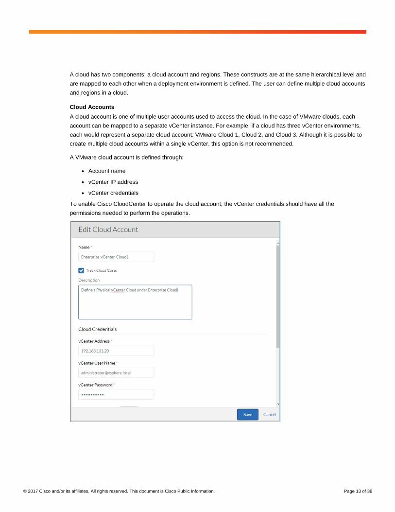
Cloud Accounts
A cloud account is one of multiple user accounts used to access the cloud. In the case of VMware clouds, each
account can be mapped to a separate vCenter instance. For example, if a cloud has three vCenter environments,
each would represent a separate cloud account: VMware Cloud 1, Cloud 2, and Cloud 3. Although it is possible to
create multiple cloud accounts within a single vCenter, this option is not recommended.
A VMware cloud account is defined through:
● Account name
● vCenter IP address
● vCenter credentials
To enable Cisco CloudCenter to operate the cloud account, the vCenter credentials should have all the
permissions needed to perform the operations.
Page 14
© 2017 Cisco and/or its affiliates. All rights reserved. This document is Cisco Public Information. Page 14 of 38
Regions
For public clouds, the definition of the region is obvious and refers to the public cloud region as defined by the
public cloud provider. For VMware clouds, a region is a logical grouping of cloud accounts with common properties
as described here. The linkage between a region and a cloud account is established through a deployment
environment, in which case the deployment environment inherits the properties of the region.
Each region is managed by a separate Cisco CloudCenter Orchestrator.
● Cloud Settings specifies:
◦ Whether the region should use IPAM
◦ The host naming strategy where the user can choose from Default where Cloud Center automatically
generates a host name or through the use of a host name call-out script
◦ Whether instances spawned should be full clones or linked clones
◦ The root disk resize configuration
● Instance Types specifies the instance type associated with a region (small, medium, large, or extra large).
● Image Mappings specifies the image repository associated with each image type published.
Cisco CloudCenter uses scripts to manage the instance provisioning lifecycle. The script repository needs to be
maintained for each region and associated with the region when it is created.
Page 15
© 2017 Cisco and/or its affiliates. All rights reserved. This document is Cisco Public Information. Page 15 of 38
Extensions
For networking, Cisco CloudCenter allows the user to provision an instance’s NIC on a vSwitch port group or a
Cisco ACI EPG and bridge domain. To integrate with Cisco ACI, the user must create an extension, which is a
subset of the Cisco ACI fabric and maps to a VRF instance and bridge domain defined in Cisco ACI. After an
extension is created, it is mapped to a deployment environment. The user needs to specify the following to create
an extension:
● Cisco ACI IP address and credentials.
● Managed Orchestrator: The name of the Cisco CloudCenter Orchestrator that manages the APIC.
● Bridge Domain Templates, adding templates that define the following fields:
◦ VRF; use the existing VRF instance or dynamically create a new VRF instance
◦ List of subnets that belong to the bridge domain
◦ Properties of subnets: private or advertised externally, neighbor discovery or route advertisement, and
prefix or querier IP address
Page 16
© 2017 Cisco and/or its affiliates. All rights reserved. This document is Cisco Public Information. Page 16 of 38
Deployment Environment
The deployment environment is an important building block in Cisco CloudCenter. It binds regions, cloud accounts,
and networks to define a physical cloud that consists of vCenter, data center, cluster, underlying network,
orchestrator, image, repository, and other properties.
A deployment environment is defined by an administrator. After the environment is defined, it can be shared with
individual users, user groups, and tenants with permissions to view, modify, and manage the environment. A user
can view only those deployment environments to which that user has access and can provision applications only in
these environments. The administrator can also limit the configurations that the user can change when that user
deploys an application.
For example, if an enterprise has five vCenter clusters that Cisco CloudCenter needs to manage, the deployment
environments can be segmented as follows:
● The administrator creates a cloud account for each vCenter.
● The administrator creates one region, which is managed through a Cisco CloudCenter Orchestrator, and
defines all the images, repositories, and policies for the region.
● The administrator creates five deployment environments that map one region to each of the five cloud
accounts.
Page 17
© 2017 Cisco and/or its affiliates. All rights reserved. This document is Cisco Public Information. Page 17 of 38
● The administrator shares these deployment environments with users, user groups, or tenants.
● The administrator can restrict a deployment environment to a specific combination of data center, cluster,
target deployment folder, and data store if needed by selecting the appropriate combination for the
environment. The administrator can also lock these settings and make them invisible to the general user,
helping ensure that any deployments in the environment use only the selected vCenter segment.
● The administrator needs to define the network to associate it with the deployment environment. Two
approaches can be used:
◦ VMware networking: In this approach, the administrator specifies the vCenter port group to which the
virtual machine NICs should be mapped. If Cisco ACI is used as the fabric, the administrator creates the
tenants, VRF instances, bridge domains, EPGs, and VMM domains manually and then selects the port
group associated with the EPG to map it to the deployment environment
◦ Cisco ACI networking: If this approach is used, the administrator works directly with the Cisco ACI
constructs:
Specify the Cisco ACI extension to use: This step links the APIC, VRF instance, and bridge domain
to the environment
Choose the VMM domain: The VMM domain is a Cisco ACI construct that groups vCenter hosts that
share a common vDS. Port groups created on the vDS are visible to all the hosts in the same VMM
domain. Whereas the data center or cluster groups the nodes from the computing perspective, the
VMM groups the nodes from the network perspective. For a valid deployment, the administrator
needs to help ensure that both the VMM and the computing cluster contain the same set of nodes
Choose the Cisco ACI tenant and EPG: The administrator can choose an existing tenant and EPG to
associate with the instance’s NIC or create a new EPG
The steps for creating a deployment environment are as follows:
1. Navigate to deployments/view/environments and create a new deployment.
Page 18
© 2017 Cisco and/or its affiliates. All rights reserved. This document is Cisco Public Information. Page 18 of 38
2. Deselect Use Simplified Networks and click Define Default Cloud Settings. Specify settings as follows:
1. The administrator usually should lock the settings for Cloud Settings to make these fields invisible to the
end users.
2. The user can further limit a deployment environment to a specific data center or cluster by selecting
these options.
3. The administrator should select Use ACI Extension and specify the Cisco ACI extension earlier created.
This step links the VRF instance and bridge domain to the deployment environment.
4. The administrator should specify the appropriate VMM to use to map it to the vCenter data center and
clusters.
5. The administrator should choose the tenant and EPGs to map them to the environment.
6. The administrator choose L3Out if this connection is used. If an L3Out connection is specified, a contract
is automatically created between the EPG and the L3Out interface.
Page 19
© 2017 Cisco and/or its affiliates. All rights reserved. This document is Cisco Public Information. Page 19 of 38
3. After a deployment environment has been created, the administrator needs to share the environment with the
users to make the environment visible to the end users. Hover the cursor over the deployment environment
and select Share from the Actions menu.
Application Profile Creation and Application Deployment
Cisco CloudCenter allows the administrator or users to create application profiles that can be deployed in the
deployment environment. For detailed steps, see the following links:
http://docs.cliqr.com/display/CCD40/Model+a+New+Application+Profile
http://docs.cliqr.com/display/CCD42/Deployment+Lifecycle+Scripts
http://docs.cliqr.com/display/CCD42/Deploy+the+Application
http://docs.cliqr.com/display/CCD42/Service+Properties
http://docs.cliqr.com/display/CCD42/Model+a+New+Application+Profile
Page 20
© 2017 Cisco and/or its affiliates. All rights reserved. This document is Cisco Public Information. Page 20 of 38
The steps for creating an application profile are summarized here:
1. Create the application profile in Cisco CloudCenter in either of these two ways:
a. Use a base OS image and install packages and applications over the base image through the lifecycle
actions in the application profile or through service definition (choose Admin > Services).
b. Create an image that contains all the necessary packages and configurations.
2. Upload the image template in vCenter. For VMware clouds, virtual machine images are uploaded to vCenter.
Application profiles can be created either from the image directly or from a snapshot of the image.
3. Define images in Cisco CloudCenter. The user needs to create a new image entity in Infrastructure > Image
and link the entity to the actual image path in vCenter.
4. Define services and link the image to the service. Cisco CloudCenter uses the concept of a service to define a
tier. A service consists of a base OS image plus lifecycle actions and other properties. The user needs to
associate the image template created with the appropriate service.
5. Create a web repository. The user needs to create a web repository to host all the scripts that are needed for
lifecycle actions. The repository needs to be hosted on a web server that is accessible to the Cisco
CloudCenter Orchestrator and Manager. With Linux, the scripts are usually in .sh format. Scripts are
associated with an instance through lifecycle actions in the application profile or through service definition
(Admin > Services). Association through service definition is preferred when the action is globally required
across all application profiles created from the service. Association through a specific application profile is
preferred for configurations that are local to a specific application.
IP Address Management
This section presents approaches to IP address management.
Static Provisioning
Static provisioning is the preferred and recommended option for IP address management. It involves the following
process:
● Cisco CloudCenter Orchestrator leases an IP address from a central enterprise DHCP server.
● The instance is statically provisioned with the IP address.
● Cisco CloudCenter Orchestrator updates the enterprise DNS with the IP address and host name mapping.
This approach is explained at http://docs.cliqr.com/display/CCD42/InfoBlox.
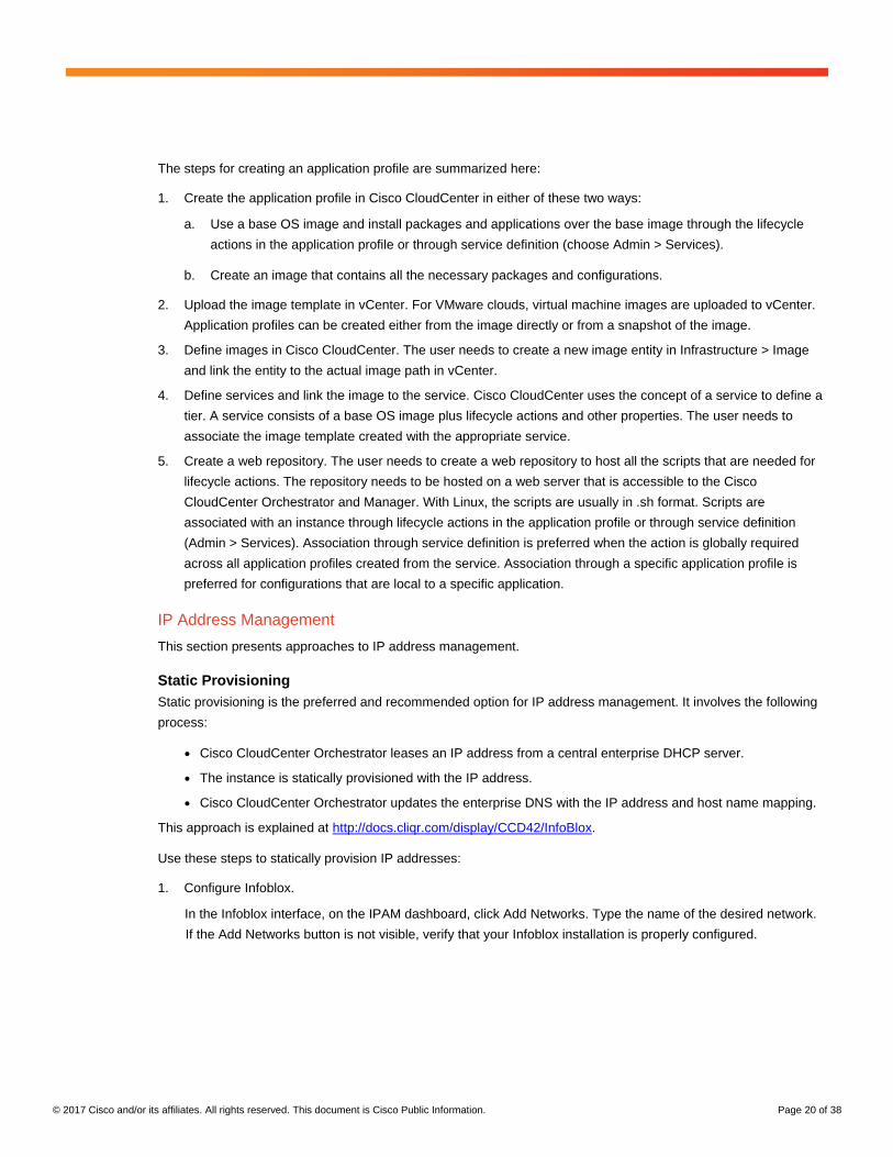
Use these steps to statically provision IP addresses:
1. Configure Infoblox.
In the Infoblox interface, on the IPAM dashboard, click Add Networks. Type the name of the desired network.
If the Add Networks button is not visible, verify that your Infoblox installation is properly configured.
Page 21
© 2017 Cisco and/or its affiliates. All rights reserved. This document is Cisco Public Information. Page 21 of 38
After creating the network, choose Data Management > DHCP and click Grid DHCP Properties. Map the dynamic
DNS (DDNS) to a DNS that you have defined. Refer to the Infoblox documentation for details about setting up a
DNS.
2. Set up Cisco CloudCenter Orchestrator.
● Cisco CloudCenter Orchestrators must have network connectivity to Infoblox Manager.
● The orchestrators must have the Infoblox Python library, along with python-requests, installed. The Infoblox
Python library can be found at https://github.com/Infoblox-Development/Infoblox-API-Python.
● Create the following directory structure on the orchestrators. This structure will be used to deploy the
application profiles.
/usr/local/osmosix/callout/ipam
Page 22
© 2017 Cisco and/or its affiliates. All rights reserved. This document is Cisco Public Information. Page 22 of 38
● Insert the Infoblox library callout.conf and the attendant script file that will be called by callout.conf. The
scripts are described in step 4.
3. Configure Cisco CloudCenter.
This step is necessary only in vCenter environments. In OpenStack and AWS environments, drop-down menus are
available to configure the IPAM settings in the Cisco CloudCenter interface.
Edit Instance IPAM Strategy in the regions in which you want to deploy the application profile to change the setting
to IPAMCallout.
4. Invoke scripts during application deployment.
When an application is deployed, Cisco CloudCenter Manager invokes a set of scripts required to deploy the
application.
Callout.conf is called when the Cisco CloudCenter Orchestrator service starts. The orchestrator maps the script
that needs to be used for a service. For example, in script shown here, createHost.py is mapped to infoblox
callout.
name=infoblox
type=exec
topic=ipam
debug=true
executable=createHost.py
reinject=true
disabled=false
In this example, the Infoblox script createHost.py is invoked when an application is deployed and IPAMCallOut is
enabled. The script chooses the network specified in the user interface and uses the parameter to obtain the IP
address in the subnet from IPAM. The IP address obtained is configured in the host as a static IP address.
#!/usr/bin/env python
import infoblox, sys, os
#Check to see if command line included enough arguments.
'''
if (len(sys.argv) < 3):
print "Usage: createHost.py <fqdn> <network CIDR>"
quit()
'''
Page 23
© 2017 Cisco and/or its affiliates. All rights reserved. This document is Cisco Public Information. Page 23 of 38
#Assign command line arguments to named variables
#fqdn = sys.argv[1] + '.test.local'
#network = sys.argv[2]
fqdn = os.environ['vmName'] + '.test.local'
network = os.environ['IPAMNetwork']
#network = '192.168.130.0/24'
#Setup connection object for Infoblox
iba_api = infoblox.Infoblox('192.168.1.2', 'admin', 'infoblox', '1.6', 'default',
'default', False)
try:
#Create new host record with supplied network and fqdn arguments
ip = iba_api.create_host_record(network, fqdn)
print 'domainName=test.local'
print 'DnsServerList=8.8.8.8'
print 'nicDnsServerList_0=8.8.8.8'
print 'nicGateway_0=192.168.131.1'
print 'nicNetmask_0=255.255.255.0'
print "nicCount=1"
print "nicIP_0=" + ip
print 'hwClockUTC=true'
print 'timeZone=Canada/Eastern'
print 'osHostname=%s' % os.environ['vmName']
except Exception as e:
print e
DHCP Provisioning
The process for configuring DHCP services in Cisco ACI is explained at
https://supportforums.cisco.com/sites/default/files/technote-aci-dhcprelay_v4.pdf.
DHCP configuration requires configuration in Cisco ACI as well as in the Infoblox DHCP server.
In the reference design discussed here, the DHCP server is provisioned centrally in the Common tenant and
provides DHCP to endpoints across multiple tenants and EPGs (Figure 4).
Page 24
© 2017 Cisco and/or its affiliates. All rights reserved. This document is Cisco Public Information. Page 24 of 38
Figure 4. DHCP Server Provisioning
Configure DHCP using the following steps:
1. Create the DHCP EPG in the Common tenant.
2. Define DHCP relay for the EPG. DHCP relay is a logical construct used to associate the DHCP server with the
bridge domains that will consume its services.
3. For each individual bridge domain that requires DHCP services, associate the bridge domain with its target
DHCP server through DHCP relay. A bridge domain can support DHCP requests from only one subnet within
its scope, referred to as the primary subnet. This behavior implies the following:
● An EPG that is associated with a bridge domain subnet other than the primary subnet will not be serviced
by DHCP.
● If a tenant has multiple EPGs that require distinct DHCP subnets, they will need to be associated with
distinct bridge domains. For example, EPG3 in Figure 4 does not support overlapped subnets. For a multi-
VRF design with overlapped subnets, multiple DHCP servers with corresponding relays need to be
provisioned.
● When an application or an instance is provisioned in Cisco CloudCenter, the application needs to be
associated with the correct bridge domain, and the instances will obtain the IP addresses configured in the
bridge domain’s primary subnet.
F5 Load-Balancer Integration
To integrate a load balancer, you initially need to set up the load-balancer instance managed by Cisco UCS
Director in the reference design described here. You also need to specify a deployment-time configuration
managed by Cisco CloudCenter closely integrated with Cisco ACI. Figure 5 summarizes the process.
Page 25
© 2017 Cisco and/or its affiliates. All rights reserved. This document is Cisco Public Information. Page 25 of 38
Figure 5. Load-Balancer Integration Using F5
Follow these steps to integrate the load balancer:
1. Add a device in Cisco ACI.
Page 26
© 2017 Cisco and/or its affiliates. All rights reserved. This document is Cisco Public Information. Page 26 of 38
2. Create a service graph template.
3. Define the load-balancer application template in Cisco CloudCenter.
Page 27
© 2017 Cisco and/or its affiliates. All rights reserved. This document is Cisco Public Information. Page 27 of 38
4. Deploy the application template in Cisco CloudCenter.
Conclusion
Cisco’s product suite comprising CloudCenter, Application Centric Infrastructure and Cisco UCS Director enables
an enterprise to seamlessly build and operate a full-featured hybrid cloud as well as automate the definition,
deployment and lifecycle management of multi-tier applications. Typical enterprise uses cases addressed by this
solution suite include:
● Application or Database-as-a-Service Clouds
● Automation of Dev Test environments
● Single Pane of Glass for Multi-Cloud Management
● Build-up and Management of Sandbox or Demo Environments
While the scope of the reference design outlined in this document is a vCenter based cloud, salient feature of
CloudCenter is its support for multiple clouds such as OpenStack, AWS, Azure, Google etc. Most of the features
outlined in this reference design cannot be supported for these other clouds as well.
Page 28
© 2017 Cisco and/or its affiliates. All rights reserved. This document is Cisco Public Information. Page 28 of 38
For More Information
Cisco Cloud Center: http://www.cisco.com/c/en/us/products/cloud-systems-management/cloudcenter/index.html.
Cisco Application Specific Infrastructure: http://www.cisco.com/c/en/us/solutions/data-center-
virtualization/application-centric-infrastructure/index.html.
Cisco UCS Director: http://www.cisco.com/c/en/us/products/servers-unified-computing/ucs-director/index.html.
Appendix: Cisco UCS Director Workflows
This appendix summarizes the Cisco UCS Director workflows for the reference design discussed in this document.
Bare-Metal Startup and Association with VMware vCenter
1. Register the Cisco UCS C-Series Server with Cisco UCS Director.
2. Initiate PXE boot with the ESX hypervisor.
3. Wait for PXE boot to complete.
4. Add the ESX hypervisor to vCenter.
5. Remove PXE boot from the server.
Page 29
© 2017 Cisco and/or its affiliates. All rights reserved. This document is Cisco Public Information. Page 29 of 38
Cisco ACI Pre-Provisioning
1. Create a VMM domain.
a. Create a dynamic VLAN pool.
b. Create the AEP.
c. Use the previously created VLAN pool and AEP to configure the VMM domain. This process will create
the vDS in the specified vCenter.
2. Create a vPC. Three workflows are created for vPC configuration for modularity. You can combine these
workflows together to create a single workflow if needed.
a. Create a vPC protection group and interface profile.
i. Create the vPC protection group as consecutive.
ii. Create the interface profile for the vPC.
Page 30
© 2017 Cisco and/or its affiliates. All rights reserved. This document is Cisco Public Information. Page 30 of 38
b. Create a vPC policy group and interface selector.
i. Create the vPC policy group.
ii. Attach the interface selector to the policy group and interface profile created earlier.
For a given vPC pair, the number of policy groups and interface selectors are the same as the number of
hosts that are part of that vPC. Each policy group represents a member of the port channel.
Page 31
© 2017 Cisco and/or its affiliates. All rights reserved. This document is Cisco Public Information. Page 31 of 38
c. Attach an interface profile to a switch profile.
i. Create the switch profile.
ii. Associate the switch selector with the switch profile.
iii. Associate the previously created interface profile with the switch profile.
3. Create the user tenant and utilities.
a. Create the tenant, VRF instance, and bridge domains.
Page 32
© 2017 Cisco and/or its affiliates. All rights reserved. This document is Cisco Public Information. Page 32 of 38
b. Configure L3Out within the tenant.
i. Create the physical domain with a static pool.
Page 33
© 2017 Cisco and/or its affiliates. All rights reserved. This document is Cisco Public Information. Page 33 of 38
ii. Create the policy group, interface, and switch profile.
Page 34
© 2017 Cisco and/or its affiliates. All rights reserved. This document is Cisco Public Information. Page 34 of 38
iii. Create the external routed network in the client’s tenant.
Page 35
© 2017 Cisco and/or its affiliates. All rights reserved. This document is Cisco Public Information. Page 35 of 38
Infoblox Provisioning and Integration with Cisco ACI
1. Create the VRF instance, bridge domain, and DHCP EPG in the Common tenant.
2. Provision the Infoblox virtual machine with two vNICs: one in the management network port group and the
other in the DHCP EPG port group.
Page 36
© 2017 Cisco and/or its affiliates. All rights reserved. This document is Cisco Public Information. Page 36 of 38
3. Add the DHCP relay label to the clients’ bridge domain.
4. For each user tenant, configure DHCP relays in the bridge domain.
Page 37
© 2017 Cisco and/or its affiliates. All rights reserved. This document is Cisco Public Information. Page 37 of 38
F5 Provisioning
1. Deploy the F5 LTM ISO image with two vNICs: network adapter 1 in the management network port group and
network adapter 2 in the quarantine port group.
4. Add the F5 LTM virtual appliance to the Common tenant and configure a service graph template and logical
device context in the client’s tenant.
a. Create an L4-L7 device in the Common tenant to deploy the device in one-arm mode.
b. Create an L4-L7 service graph template in the client’s tenant for one-arm deployment using the HTTP
virtual server profile.
c. Create a logical device context in the client’s tenant on any contract using the service graph template
previously created.
Page 38
© 2017 Cisco and/or its affiliates. All rights reserved. This document is Cisco Public Information. Page 38 of 38
Printed in USA C11-738412-00 01/17