Management Framework of Automotive Full Service Supplier in Computer Aided Engineering (CAE) by Hai The Truong Submitted to the System Design and Management Program in Partial Fulfillment of the Requirements for the Degree of Master of Science in Engineering and Business Management at the Massachusetts Institute of Technology May 2001 The author hereby grants MIT permission to reproduce and distribute publicly paper and electronic copies of this thesis document in whole or in part. Signature of Author System Design and Management Program May, 2001 Certified by Daniel Whitney - Senior Resea Scientist Center for Technology, Policy & Industrial Development Thesis Supervisor Accepted by Paul A. Lagace LFM/SDM Co-Director Professor of Aeronautics & Astronautics and Engineering Systems Accepted by Stephen C. Graves LFM/SDM Co-Director Abraham Siegel Professor of Management MASSACHUSETTS INSTITUTE OF TECHNOLOGY AUG 1 20OZ BARKER IBAG LIBRARIES
Transcript
Management Framework of Automotive Full Service
Supplier in Computer Aided Engineering (CAE)
by
Hai The Truong
Submitted to the System Design and Management Program
in Partial Fulfillment of the Requirements for the Degree of
Master of Science in Engineering and Business Management
at the
Massachusetts Institute of Technology
May 2001
The author hereby grants MIT permission to reproduce and distribute publicly paper and electronic copies ofthis thesis document in whole or in part.
Signature of AuthorSystem Design and Management Program
Center for Technology, Policy & Industrial DevelopmentThesis Supervisor
Accepted byPaul A. Lagace
LFM/SDM Co-DirectorProfessor of Aeronautics & Astronautics and Engineering Systems
Accepted byStephen C. Graves
LFM/SDM Co-DirectorAbraham Siegel Professor of Management
MASSACHUSETTS INSTITUTEOF TECHNOLOGY
AUG 1 20OZ BARKERIBAG
LIBRARIES
2
MANAGEMENT FRAMEWORK OF AUTOMOTIVE FULL SERVICE SUPPLIER INCOMPUTER AIDED ENGINEERING (CAE)
By
Hai The Truong
Submitted to the System Design & Management Program in Partial Fulfillment of Requirements of the
Degree of Masters of Science in Engineering and Management
Abstract
Outsourcing design & development works to supplier is a new and aggressive trend in the automotiveindustry. Its purpose are many folds including reducing development & product costs, reducing thecomplexity of supplier management and increasing shareholder value by reducing fixed asset costs andrefocusing the company resource in creating new value. CAE is an important and integral part of design anddevelopment process and often overlooked however in the outsourcing strategy due to its small cost. Thereis a strong tension between two strategies of dealing with CAE outsourcing. The first strategy is keeping allCAE works in house as before and continues to direct supplier on "how" to design its commodity. Thisstrategy could run the risk of a long term lower supplier efficiency and innovation. The second strategy is todelegate to supplier full responsibility of the design and development of its commodity including the use ofCAE. This option will often run into operational problems of potential low quality, reworks and delay due tomany factors like supplier initial CAE learning curve and the immaturity of the vehicle manufacturer's systemengineering target cascading process. There are interfaces in both process and technical that the VehicleManufacture (VM) must understand in order to manage.
Computer Aided Engineering (CAE) technology is widely used throughout the Product Development (PD)process. Instead of the traditional "hardware" approach of "build-break-build" to develop the vehicle, theVM rely on CAE to speed up the "build-break-build" process digitally. With its potential to reduce PD time,reduce cost and improve performance, CAE could be a "core competence". In this thesis a useful frameworkin looking at core competency is used to address the type of CAE outsourcing.
Not all the benefits and pitfalls of outsourcing CAE to supplier are well understood and captured in literatureor in practice. At least in one of the big vehicle manufacturers (the focus of this thesis) low understanding ofCAE outsourcing process is believed to be the additional reason besides cost for low attention to the area of
outsourcing CAE. This thesis takes a closer look at the current practice of CAE outsourcing by usingdifferent analysis frames like Engineering-Design-Analysis (EDA), System Engineering in target cascadingand System Dynamic loop in the managing project dynamics.
3
TABLE OF CONTENTS
C INTRO D U C TIO N ..................................................................................................................... 9
1.5 THEPROBLEM :.................................................................................................................121.6 THE PRINCIPLE.OF VM OUTSOURCING STRATEGY:..............................................................14
1.7 SUMMARY OF FSS SKILL SET EXPECTATION:................................................................... 141.8 THE SCOPE & A IM ............................................................................................................ 151.9 RESEARCH A PPROACH ...................................................................................................... 16
2 TRENDS IN THE ECONOMY / AUTOMOTIVE ............................................................. 17
2.1 TRANSITION TO THE NEW ECONOMY............................................................................ 172.1.1 Globalization (bigger market).................................................................................. 172.1.2 Technology Acceleration (faster market)................................................................... 18
2.2 CURRENT AUTOM OTIVE INDUSTRY TREND ..................................................................... 182.2.1 Shareholder Value........................................................................................................182.2.2 Customer Satisfaction............................................................................................... 192.2.3 Platform D e-proliferation ......................................................................................... 19
3 CAE VALUE IN PRODUCT DEVELOPMENT....................................................................20
3.1 AUTOM OTIVE ENTERPRISE VALUE ................................................................................ 213.2 PRODUCT DEVELOPM ENT VALUE ................................................................................... 21
3.2.1 Five goals ofproduct developm ent:........................................................................... 22
3.3 CAE VALUE ..................................................................................................................... 26
3.3.1 Uniqueness about CAE managem ent ......................................................................... 26
3.3.2 CAE Value Stream ........................................................................................................ 273.3.3 Can CAE be outsourced? .............................................................................................. 28
3.3.4 Barriers to CAE effectiveness................................................................................... 31
4.1 ABOUT OUTSOURCING ................................................................................................. 33
4.1.1 Outsourcing is "re-organization".............................................................................. 33
4.1.2 Outsourcing is about "specialization"....................................................................... 33
4.1.3 O utsourcing is a "strategic" managem ent tool ............................................................ 33
4.2 OUTSOURCING STRATEGY.............................................................................................354.2.1 FSS process - the drive towards modularity.............................................................. 35
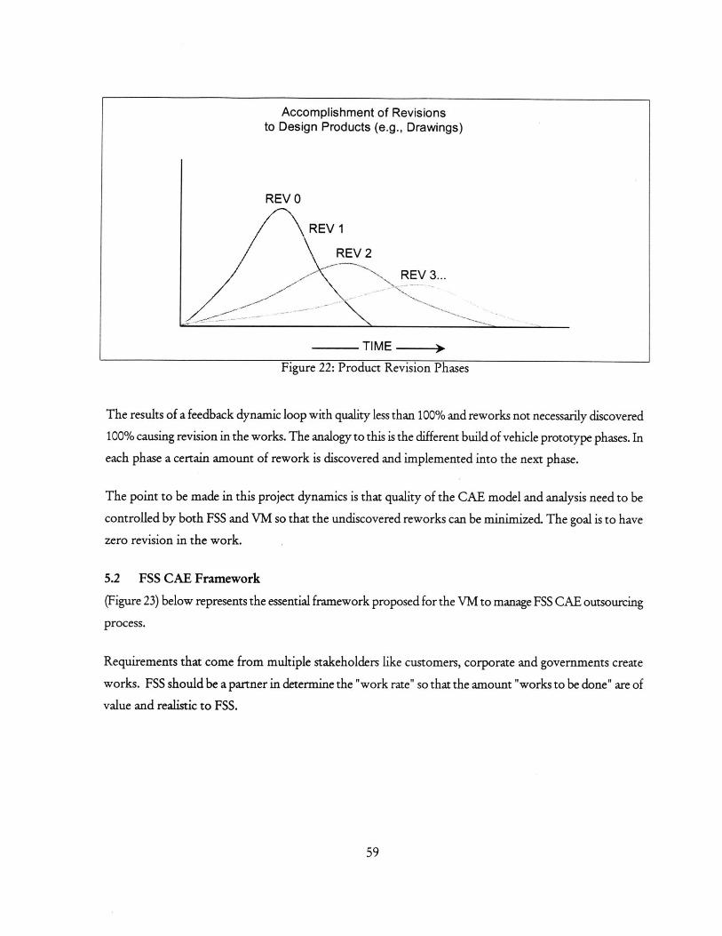
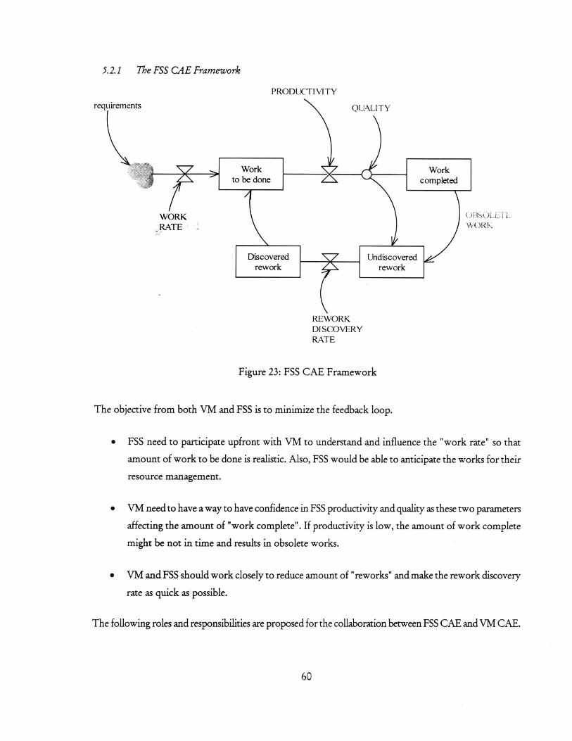
5.2 FSS CAE FRAMEWORK .................................................................... ,...............................595.2.1 The FSS CAE Framework .......................................................................................... 605.2.2 Communication ............................................................................................................ 61
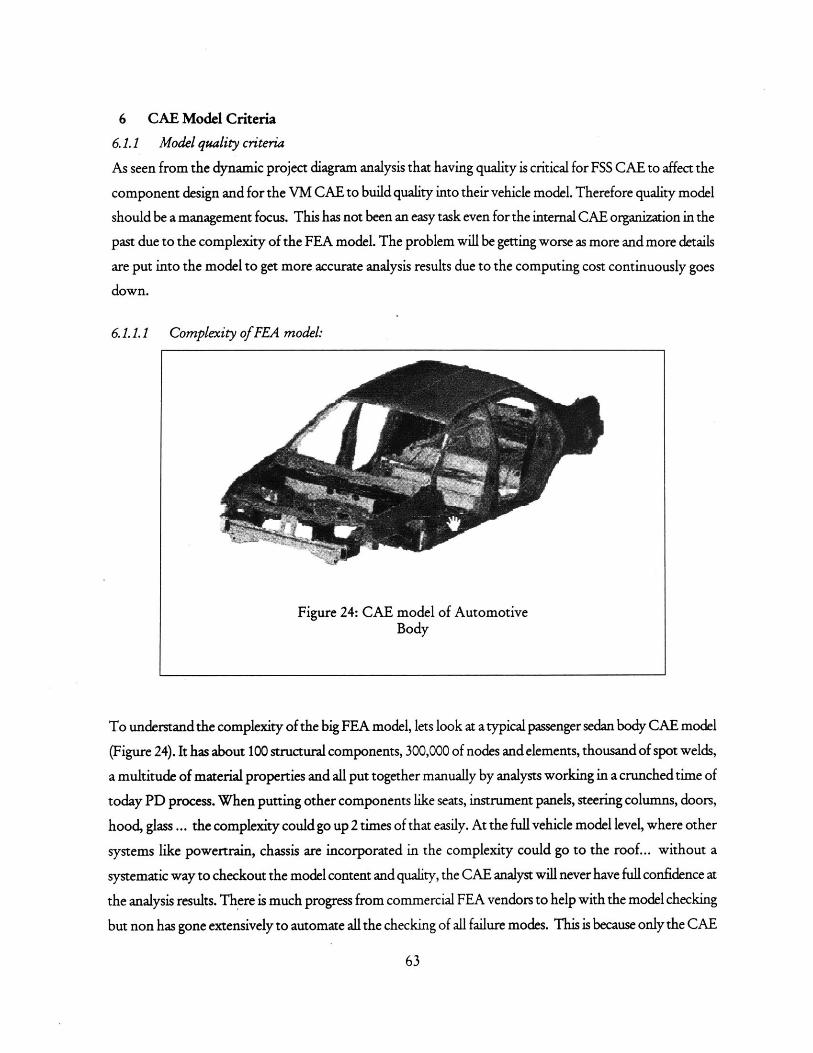
6 CAE M O DEL CRITERIA .................................................................................................. 63
6.1.1 M odel quality criteria ................................................................................................ 63
7 SYNTH ESIS ............................................................................................................................ 67
7.1 FSS CAE~PRINCIPLES ....................................................................................................... 677.1.1 VM CAE is ultimately responsible for all CAE works. .................................................... 677.1.2 Consider Upstream Requirements & Downstream Capability...................677.1.3 Focus on CAE M odel Quality Verification................................................................. 677.1.4 Encourage FSS CAE in pursuing Upfront Analysis .................................................... 677.1.5 Optimization incentive ............................................................................................. 677.1.6 Organize in assisting FSS process .............................................................................. 687.1.7 Knowledge Base CAE:............................................................................................. 68
Number PageFIGURE 1: TYPICAL STEERING COLUM N SYSTEM ............................................................................. 10FIGURE 2: IDEAL CAE PROCESS...................................................................................................I I
FIGURE 3: CURRENT TARGET CASCADE ......................................................................................... 13
FIGURE 4: VALUES ............................................................................................................................ 19FIGURE 5: THE BIG PICTURE .............................................................................................................. 21FIGURE 6: GOAL CASCADING.............................................................................................................25FIGURE 7: CAE VALUE STREAM ........................................................................................................ 27
FIGURE 8: MATRIX OF DEPENDENCY AND OUTSOURCING ............................................................... 29
FIGURE 9: UPFRONT CA E .................................................................................................................. 31FIGURE 10: SUPPLIER HIERARCHY ..................................................................................................... 35FIGURE 11: NUM BERS OF REW ORKS ................................................................................................... 40
FIGURE 12: POTENTIAL W ASTES IN CAE........................................................................................ 42FIGURE 13: TRADITIONAL ROLES OF ED A ...................................................................................... 44
FIGURE 14: DIFFERENT W AYS OF ED A INTERACTION..................................................................... 45
FIGURE 15: STEERING COLUM N ......................................................................................................... 48
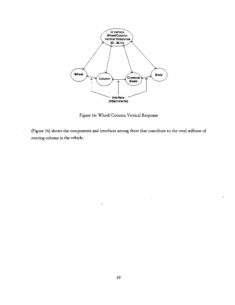
FIGURE 16: W HEEIJCOLUM N VERTICAL RESPONSE ......................................................................... 49
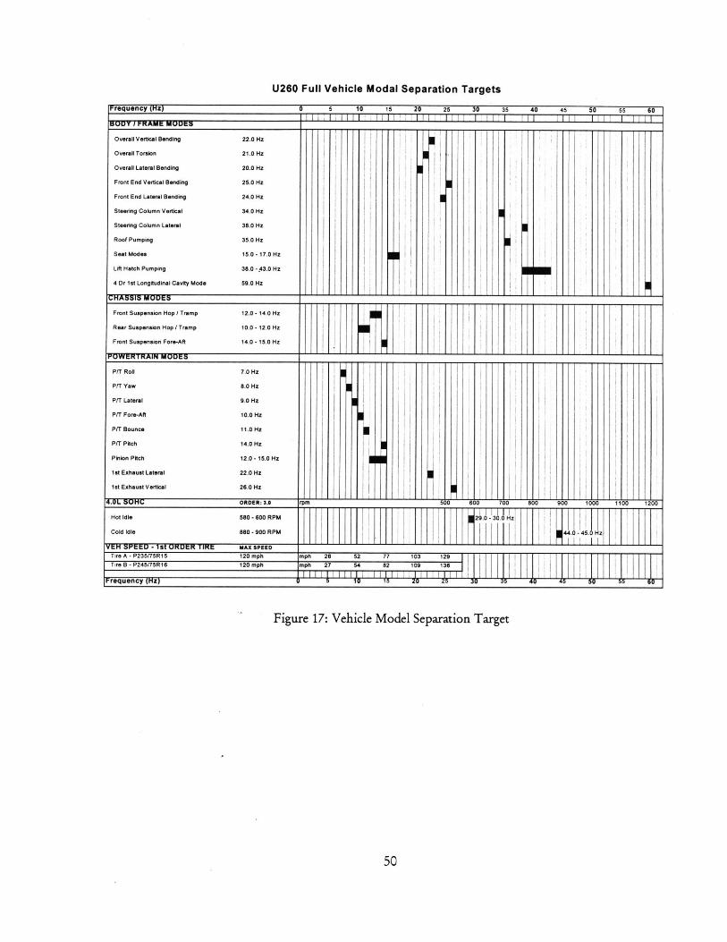
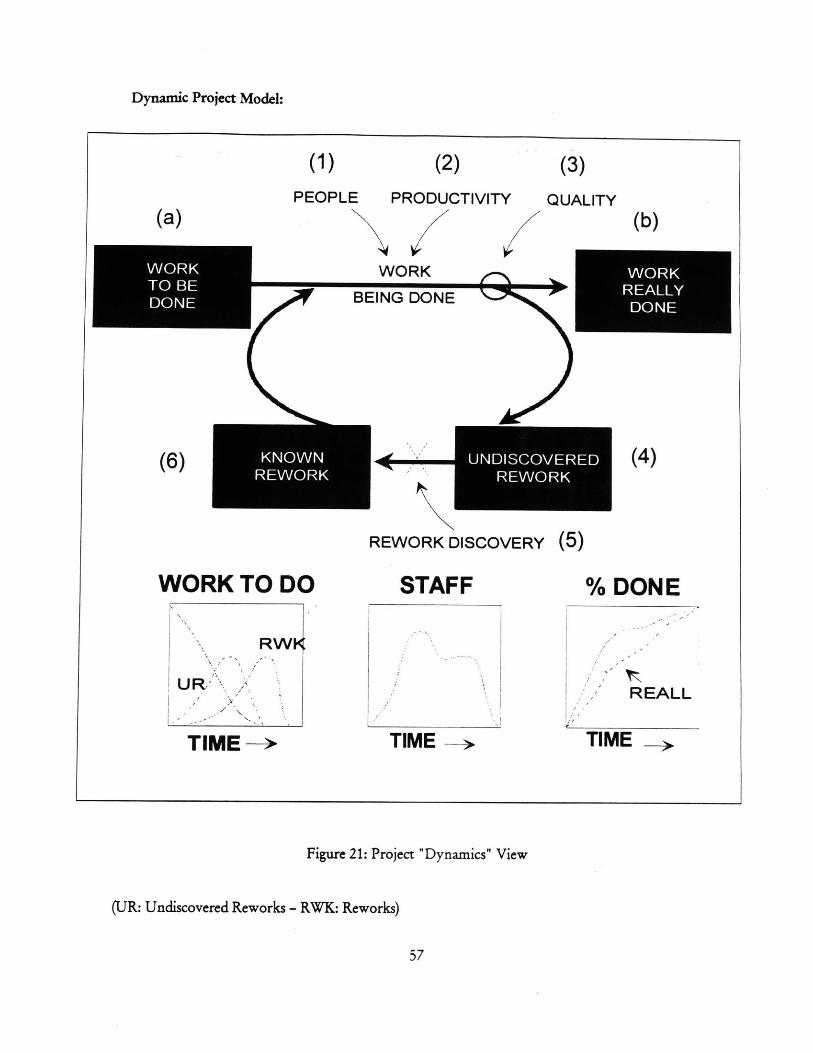
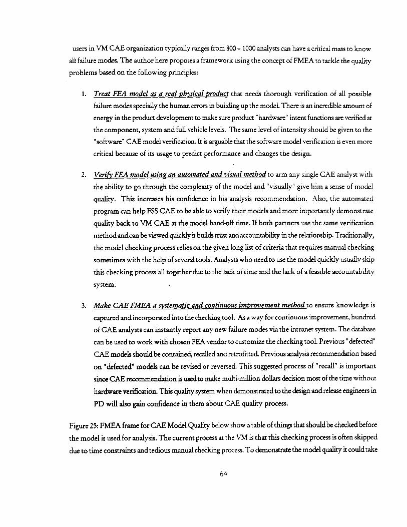
FIGURE 17: VEHICLE M ODEL SEPARATION TARGET......................................................................... 50FIGURE 18: CASCADED FREQUENCY TARGET ................................................................................. 51FIGURE 19: SYSTEM DYNAM IC PROJECT......................................................................................... 54FIGURE 20: PROJECT "STATIC" VIEW ................................................................................................. 55FIGURE 21: PROJECT "DYNAM ICS" VIEW ........................................................................................ 57FIGURE 22: PRODUCT REVISION PHASES ........................................................................................ 59FIGURE 23: FSS CAE FRAM EW ORK ................................................................................................... 60FIGURE 24: CAE MODEL OF AUTOMOTIVE BODY ............................................................................ 63FIGURE 25: FMEA FRAME FOR CAE MODEL QUALITY ................................................................... 66
ACKNOWLEDGMENTS
The author wishes to acknowledge Dr. Daniel Whitney, Senior Research Scientist. Center for Technology,Policy & Industrial Development at MIT for valuable guidance in pursuing this thesis works.
7
GLOSSARY
CAE. Computer Aided Engineering (majority usages from application of finite element method)
Core Commodity. Commodity expertise is exclusive or most efficient or strategically.
Core Competency. Core competency is the collective know-how of an organization that gives it acompetitive advantage. This know how is a result of learning that is driven by business strategy and builtthrough a process of continuous improvement and enhancement that may span a decade or longer. (Grady,Successful Software Process Improvement)
Full Service Supplier: Supplier that has full responsibility in design, develop, test, fix-up and manufacturing.
NVH. Noise, Vibration and Harshness.
Productivity. Work accomplished per hour of effort, regardless of completeness or correctness
Quality. Fraction of work just accomplished that is correct and complete, i.e. will not need rework.
Vehicle Manufacturer (VM). Automotive major companies (GM, Ford, Chrysler)
Waste. Anything that does not add value to the final consumer
8
1 INTRODUCTION
1.1 Introduction
One of the latest areas of product development that a vehicle manufacturer (VM) starts partially outsourcing
is CAE (Computer Aided Engineering). Not long ago, suppliers are limited to just the manufacturing of the
products according to a set of given design specifications. Now most of them are being asked to take on a
full array of additional responsibilities in the development, design & verification process. This so called Full
Service Supplier (FSS) strategy is viewed as a new business model to gain further advantages in 3 areas
1. Maximizing the utilization of supplier expertise
2. Achieving greater product development efficiency
3. Creating competitive processes and products
As the suppliers are "forward integration" insisted by the vehicle manufacturers, new players along with their
processes and tools are brought in and must be matched up with the existing VM PD structure. The
fuzziness nature of the PD "front-end" where information is not in concrete forms creates the complexity of
coordination. The complexity in cascading functional targets from vehicle level down to FSS commodity
level requires more than a written contract since the current product development process is a highly
iterative. While much of literatures have been written to address the outsourcing make and buy decision and
about collaborating framework in general, non has addressed a unique situation of outsourcing CAE in
automotive industry. Not much-practical experiences and lesson learns either exists for management
guidance of the issue. Being a subset of general outsourcing, CAE outsourcing has similar issues and benefits
that will be fully analyzed later in this paper. What new and interesting is the uniqueness of CAE role in PD
process that managing it requires a particular understanding. Where would CAE contributing to the overall
goals of PD? What is the CAE value stream and its core competency? What portion then of CAE is
outsourced? Where is the management attention should be focused to realize the benefits? This is new
paradigm thinking for VM CAE management since many efforts in the past 10 years has been mostly
internally focused in trying to improve the effectiveness of CAE. Now there is anew way, better or worse, of
conducting the CAE business: by outsourcing a portion of it! The emerging issues of managing FSS CAE
should be carefully looked at.
1.2 What are being outsourced?
Examples of typical commodities being outsourced from the ground up of the vehicle includes: tires, wheels,
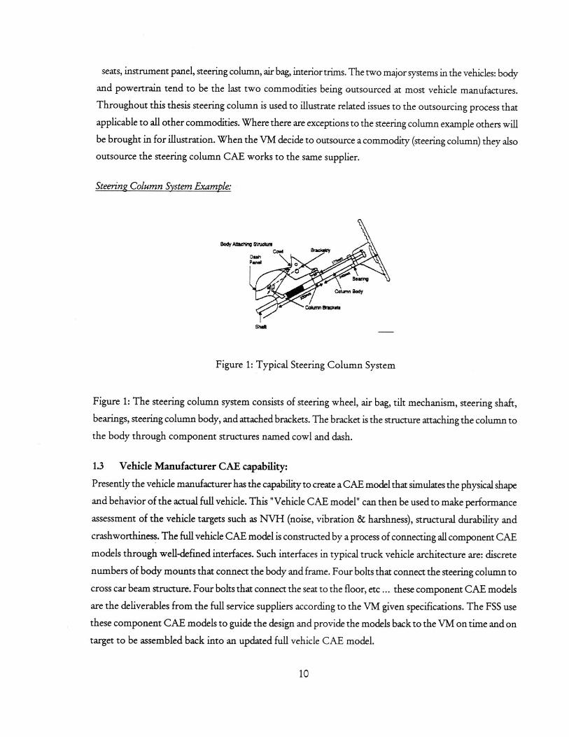
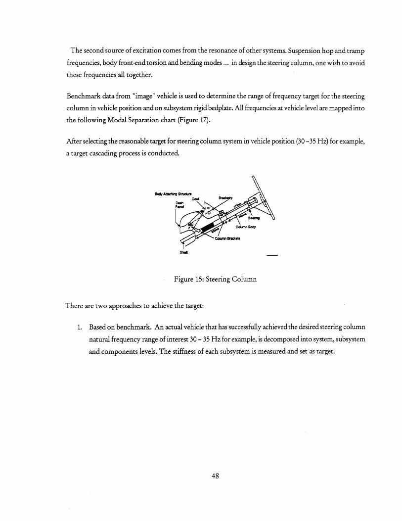
seats, instrument panel, steering column, air bag, interior trims. The two major systems in the vehicles: bodyand powertrain tend to be the last two commodities being outsourced at most vehicle manufactures.Throughout this thesis steering column is used to illustrate related issues to the outsourcing process thatapplicable to all other commodities. Where there are exceptions to the steering column example others willbe brought in for illustration. When the VM decide to outsource a commodity (steering column) they alsooutsource the steering column CAE works to the same supplier.
Steering Column System Example:
eenemaBeen%
CdmBettyg
Figure 1: Typical Steering Column System
Figure 1: The steering column system consists of steering wheel, air bag, tilt mechanism, steering shaft,bearings, steering column body, and attached brackets. The bracket is the structure attaching the column tothe body through component structures named cowl and dash.
1.3 Vehicle Manufacturer CAE capability:
Presently the vehicle manufacturer has the capability to create a CAE model that simulates the physical shape
and behavior of the actual full vehicle. This "Vehicle CAE model" can then be used to make performance
assessment of the vehicle targets such as NVH (noise, vibration & harshness), structural durability and
crashworthiness. The full vehicle CAE model is constructed by a process of connecting all component CAE
models through well-defined interfaces. Such interfaces in typical truck vehicle architecture are: discrete
numbers of body mounts that connect the body and frame. Four bolts that connect the steering column to
cross car beam structure. Four bolts that connect the seat to the floor, etc ... these component CAE models
are the deliverables from the full service suppliers according to the VM given specifications. The FSS use
these component CAE models to guide the design and provide the models back to the VM on time and on
target to be assembled back into an updated full vehicle CAE model.
10
1.4 Target Decomposition Process:
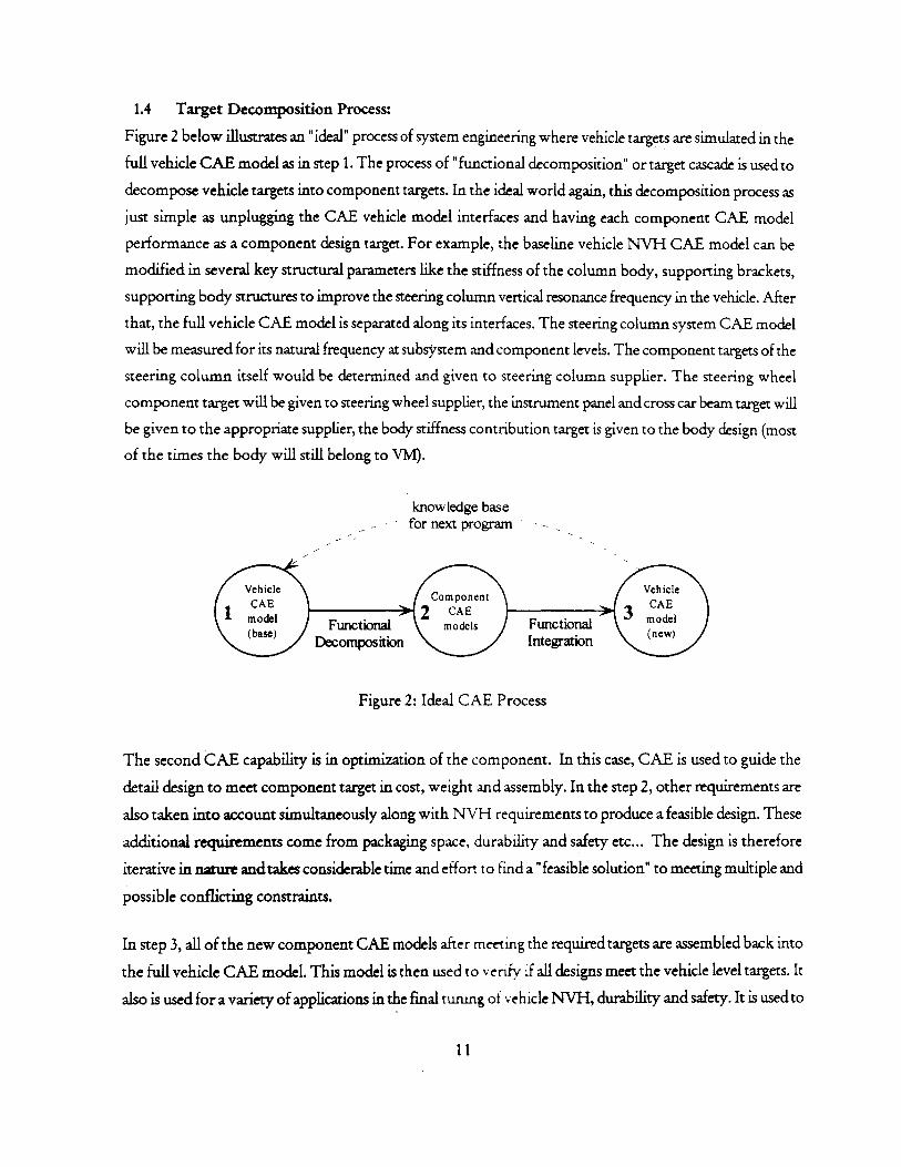
Figure 2 below illustrates an "ideal" process of system engineering where vehicle targets are simulated in the
full vehicle CAE model as in step 1. The process of "functional decomposition" or target cascade is used to
decompose vehicle targets into component targets. In the ideal world again, this decomposition process as
just simple as unplugging the CAE vehicle model interfaces and having each component CAE model
performance as a component design target. For example, the baseline vehicle NVH CAE model can be
modified in several key structural parameters like the stiffness of the column body, supporting brackets,
supporting body structures to improve the steering column vertical resonance frequency in the vehicle. After
that, the full vehicle CAE model is separated along its interfaces. The steering column system CAE model
will be measured for its natural frequency at subsystem and component levels. The component targets of the
steering column itself would be determined and given to steering column supplier. The steering wheel
component target will be given to steering wheel supplier, the instrument panel and cross car beam target will
be given to the appropriate supplier, the body stiffness contribution target is given to the body design (most
of the times the body will still belong to VM).
knowledge basefor next program
Vehicle Component Vehicle
CAE 2 CAE 3 CAE(I Func tio models Functional mode
Decomposition Integration
Figure 2: Ideal CAE Process
The second CAE capability is in optimization of the component. In this case, CAE is used to guide the
detail design to meet component target in cost, weight and assembly. In the step 2, other requirements are
also taken into account simultaneously along with NVH requirements to produce a feasible design. These
additional requirements come from packaging space, durability and safety etc... The design is therefore
iterative in nature and takes considerable time and effort to find a "feasible solution" to meeting multiple and
possible conflicting constraints.
In step 3, all of the new component CAE models after meeting the required targets are assembled back into
the full vehicle CAE model. This model is then used to venify if all designs meet the vehicle level targets. It
also is used for a variety of applications in the final tunng of vehicle NVH, durability and safety. It is used to
11
determine root cause of problem in vehicle level and finally serving as a good baseline model for future
programs.
1.5 The Problem:
Not all vehicle tagets can be decomposed into component targets.
Example of that is the performance of the steering column system in crash test. To meet the requirement of
occupant chest deflection in a vehicle frontal impact there are many parameters involved like the body and
frame crush distance and pattern, the engine movement and intrusion into the body's dash and floor space.
The air bag inflator parameters (inflating rate, volume, venting) mounted on the steering column and wheel.
The steering column stiffness, the collapsible rate of the steering column in impact and many other factors
... Simply there are too many interactions among all mentioned parameters and more that VM often rely on
the engineering experience and incremental change to manage the complexity.
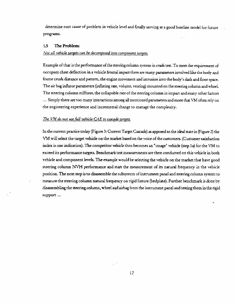
The VM do not use full vehicle CAE to cascade targets.
In the current practice today (Figure 3: Current Target Cascade) as apposed to the ideal state in (Figure 2) the
VM will select the target vehicle on the market based on the voice of the customers. (Customer satisfaction
index is one indication). The competitor vehicle then becomes an "image" vehicle (step 1a) for the VM to
exceed its performance targets. Benchmark test measurements are then conducted on this vehicle in both
vehicle and component levels. The example would be selecting the vehicle on the market that have good
steering column NVH performance and start the measurement of its natural frequency in the vehicle
position. The next step is to disassemble the subsystem of instrument panel and steering column system to
measure the steering column natural frequency on rigid fixture (bedplate). Further benchmark is done by
disassembling the steering column, wheel and airbag from the instrument panel and testing them in the rigid
support ...
12
knowledge basefor next program
Vehicle ComponentVehicleCAE -------- 2 C AoEn CAE(be) models Functional(base) nw
9 Integration
FunctionalDecomposition
image (physical measurement)Svehicle
Figure 3: Current Target Cascade
Vehicle CAE model (step 1) plays a supporting role in that it can provide the baseline data for comparison
with the image vehicle.
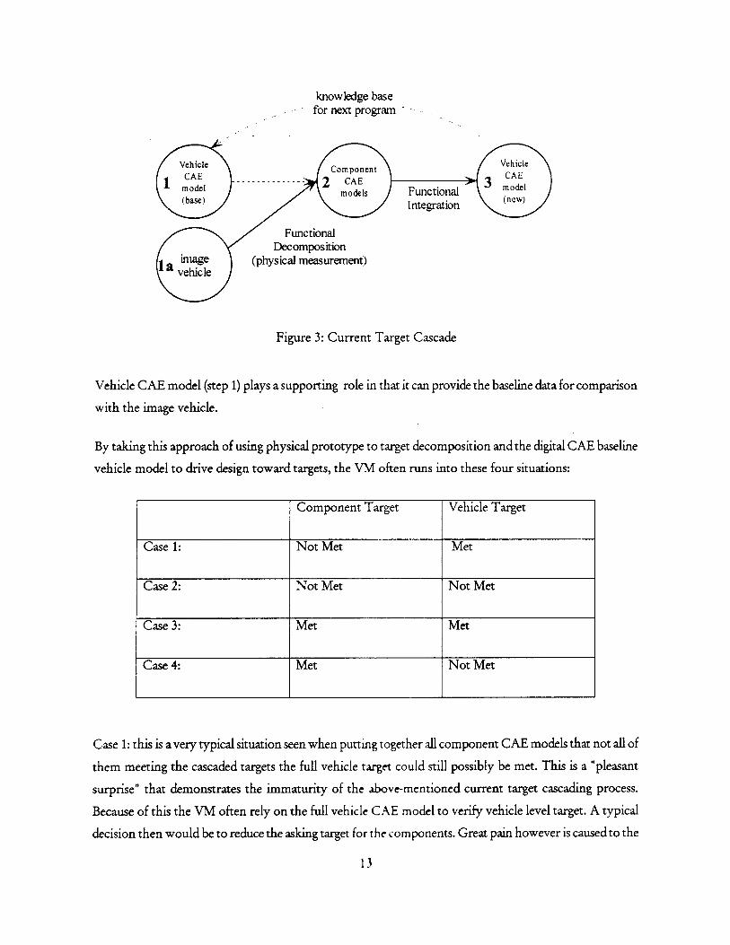
By taking this approach of using physical prototype to target decomposition and the digital CAE baseline
vehicle model to drive design toward targets, the VM often runs into these four situations:
Component Target Vehicle Target
Case 1: Not Met Met
Case 2: Not Met Not Met
Case 3: Met Met
Case 4: Met Not Met
Case 1: this is a very typical situation seen when putting together all component CAE models that not all of
them meeting the cascaded targets the full vehicle target could still possibly be met. This is a "pleasant
surprise" that demonstrates the immaturity of the above-mentioned current target cascading process.
Because of this the VM often rely on the full vehicle CAE model to verify vehicle level target. A typical
decision then would be to reduce the asking target for the components. Great pain however is caused to the
13
suppliers involved. They could have spent great amount of efforts to achieve the component targets that
proved to be not so critical for system level performance.
Case 2 / 3 demonstrated the target cascading is appropriate.
Case 4 is an "un-pleasant surprise" and this problem is difficult to deal with. Suppliers are usually not so
happy to revise their targets upward and spending more time and money to meet new targets late in the
product development process.
The challenge of management step 2 and 3 when commodity is outsourced-
The difficulty in target decomposition and the continuing of selecting the physical test as benchmarks
mentioned above creates challenge in managing the commodity outsourcing. Suppliers are now given targets
cascaded from different functional attributes (NYH, safety, durability) that may be of conflict of each other
and also may in conflict with traditional design targets like package, assembly and cost. The conflict can only
be known and resolved after the intensive study and CAE component analysis. Cascaded targets then could
be re-negotiated and trade-offs process can be conducted. Target negotiation and trade-offs are harder to do
than before if involved commodities belong to different suppliers. The long-term remedy for this problem is
to have bigger and bigger supplier so that the single mega supplier could perform the trade-off. The co-
location of all suppliers together in one development center is also a solution for fast trade-off process.
1.6 The principle of VM outsourcing strategy:
The principle of outsourcing the component to supplier is that supplier design engineer will replace the "VM
component design engineer". In this way the FSS component design engineer has one advantage in that there is a
strong tie back into manufacturing. When a design is proposed by him most likely all manufacturing and cost
issues already worked out in advance. There are two modes of communication between VM and FSS. To
ensure smooth communication with VM PD structure, FSS component engineer is requiredto be on-board
collocated in the VM facility if it is judged that the amount of communication with VM activities is daily. If
needed communication is judged only occasional FSS component engineer presentation at the regular
meetings at VM will be enough. FSS CAE communication with VM CAE has been in this ladder mode
partially because FSS CAE would like to centralize their CAE capability at their home office.
1.7 Summary of FSS skill set expectation:
0 Project Management: FSS is expected to be a design leader that owns the design process. FSS should
understand the VM product structure in order to interface effectively. FSS is responsible to design
to cost target and has capability in project management.
14
* Product: FSS is expected to be the expert in customer wants as they apply to the supplier's
commodity. FSS conducts competitive benchmarking. FSS must understand how to translate
customer wants into effective design solution. They must also have expertise in developing design
specification to effectively deliver the functional requirements of the FSS commodity.
0 Core Design: FSS is expected to have skills in quality/ reliability, system engineering, prototype build
and launch, craftsmanship and analytical capability (CAE).
This principle when applied to the CAE will often cause operational problem. One FSS CAE analyst could not
be assumed to equal to one VM CAE analyst.
1.8 The Scope & Aim
This thesis will not address the entire problem of automotive outsourcing. It rather focuses on the business
of outsourcing CAE. However, there will be considerable business analysis upfront that will demonstrate the
benefits of outsourcing the design and development to FSS and thus making the case for outsourcing CAE
works to them as well.
The thesis is not advocating for the transferring of CAE works entirely to the FSS and thus "reducing" the
CAE workforce. It is not definitely about "downsizing" by getting rid of in-house works and go
"contracting". It is about "re-organizing" the boundary of responsibility and expanding the business by
applying existing CAE resource somewhere else in the value stream that could be a competitive advantage
for the VM. It is about how to manage the supplier component CAE (the target inputs and design
optimization) and the integration back into the full vehicle CAE with intended quality and timing. The VM
CAE resource should then be redeployed to make the vehicle CAE model more predictable to increase its
usefulness more in the target cascading process and in the later verification phase.
15
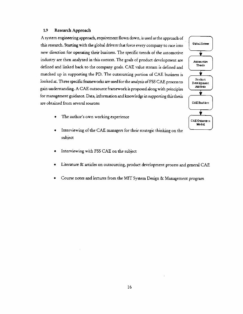
1.9 Research Approach
A system engineering approach, requirement flown down, is used as the approach of
this research. Starting with the global drivers that force every company to race into
new direction for operating their business. The specific trends of the automotive
industry are then analyzed in this context. The goals of product development are
defined and linked back to the company goals. CAE value stream is defined and
matched up in supporting the PD. The outsourcing portion of CAE business is
looked at. Three specific frameworks are used for the analysis of FSS CAE process to
gain understanding. A CAE outsource framework is proposed along with principles
for management guidance. Data, information and knowledge in supporting this thesis
are obtained from several sources:
* The author's own working experience
* Interviewing of the CAE managers for their strategic thinking on the
subject
" Interviewing with FSS CAE on the subject
* Literature & articles on outsourcing, product development process and general CAE
* Course notes and lectures from the MIT System Design & Management program
16
ObbtDrivar
Au~cotireTrads
ProdactDmbme
CAE Rablrs
CAE Oitsourc eModel
2 TRENDS IN THE ECONOMY / AUTOMOTIVE
2.1 Transition to The New Economy
Automotive industry has been known as the flagship of the old industry economy where investors measured
its values through quantifiable physical assets owned by the company: lands, manufacturing facilities, raw
materials and inventory. In the new information economy of today, values are measured very differently.
They are based on human capital, R&D, innovation and networks. Understanding these intangibles is
important in the effort of improving company total market value. Existing measures today however are
insufficient at expressing the value of the new industry even for the financial measurement. As one senior
portfolio manager said "Financial performance tells me what a company has already done, Non-financial
performance tells me what it is likely to do." The asset of today economy is knowledge that resides in
people, product and organization. The two biggest drivers are the globalization and the accelerated
technological growth. Together they create an information age that information is ubiquitously available.
The production of information instead of physical things requires different skill sets from the workers. It
requires knowledge. It changes the behaviors of the consumers, the investors and the competitions.
2.1.1 Globalization (bigger market)
Throughout history, industry revolution comes as people are connected together. The railroad system that
connected American towns together brought local competition into a national scene sparking a new
industrial revolution. Similarly, world peace today opens up country borders to physically connect people
from all over the world. The national market transforms into a bigger global market. Although international
business existed at the time of the Cold War, but political stability of world today gives focus and confidence
for developed and developing countries to adapt free trade has made automotive in particular a truly global
industry. In short, the bigger market gives the followings:
" More invatorswith higher expectation for their return on investment (ROI) will make capital mobility
increases. Automotive industry will have to change business process to compete not only with each
other in the same field but with other newly created information industries for investor's capitals.
With the historical heavy asset dependent, the VM must transform its business model to re-deploy
asset throughout its value chain. Outsourcing to FSS is one of the strategic management tools to
accomplish this.
* More consumers with higher purchasing power due to the converging of standard living around the
world. This puts the consumers in control and poise to change a historical "push" industry to a17
consumer "pull" industry. It is about time the VM will have to build to order specified from those
sophisticated consumer needs.
* More competitions with similar access to technology will create even a more competitive environment
for survival.
2.1.2 Technology Acceleration (faster market)
If globalization gives a bigger market, accelerated technology growth gives the market a speed! Digitalization
creates and transforms information at the speed of light. While the invention of the telephone mechanized
the business, the existence of the Internet today brings richer medium of exchanging information that
enables business to be anywhere and any time. The new way of doing business like E-Commerce promises to
drastically reduce the business friction.
If the automotive industry was a fantastic industry of the last century, it anticipates having an extraordinary
potential in this century because it has become global. As Ford CEO Jac Nasser said, "when a new country is
formed, first it designs a flag, then a national anthem and then a car company." There are still plenty of
countries with enormous number of people ready to enjoy the personal freedom of being on wheel.
2.2 Current Automotive Industry Trend
As more investors are expecting higher and consistent return of their investment, meeting their expectation
is a financially competitive advantage. As customers are in command, what a car will do is to support their
lifestyles. This creates a potential for the VM to be the providers of "transportation" and other lifestyle
services rather than just the facilitators of "vehicle ownership". Customer satisfaction becomes the highest
objective of the consumer focus company. And finally, as there are more competitions, the VM must find a
way to leverage the economy of scales to further reduce the cost structure. The drive to modularity to
achieve platform de-proliferation will enable the VM to do that.
2.2.1 Shareholder Value
The first challenge in automotive industry is increasing "shareholder value". On this, the VM still rely on an
economy of scale strategy. To gain incremental volume the VM embrace furiously a strategy of globalization,
consolidation and platform de-proliferation 1. There is however high barrier to entry cost to the emerging
market like the required plant co-location that VM must meet to be able to extend their global footing.
Organization boundaries are more permeable, roles and responsibility shift in the new product development
process. Speed of product development increases fast as new technology (E-commerce) reduces business
transaction frictions and brings competition from around the world.
18
2.22 Customer Satisfaction
The second challenge to sustain the consumer base is the renew effort towards mastering the consumer
satisfaction. Consumer satisfaction is the key determinant of additional product and service sales. Retail
environment illustration of this point indicates that a consumer will leave the sore if he or she doesn't find
the first product they are looking for with a reasonable amount of time. Conversely, if they do find it, they
will not only stay, but will also add further five or six items to their list of purchases. In a similar vein, a
satisfied customer can lead to an average of between 9 to 11 referrals. There are two distinctive consumer
demands that global VM must satisfy. For the established market, the products are replacement products and
will serve to fit the customer's lifestyle. For the emerging market the vehicles remain basic transportation
needs and personal freedom. There is a challenge-for the new product development processes on the global
scale that can meeting both.
2.2.3 Platform De-proliferation
Platform architecture is the answer the VM rely on to implement economy of scales. It enables the reduction
in cost. It gives the flexibility to tailor to the needs of different consumers markets and the speed to market.
Growing trend in the industry is that suppliers will become bigger and will
take on the role of a module supplier. CMETriVALUS
It is useful to think of any business as about providing value to the final
customers. There are three components: creating values, capturing values VU DELER
and delivering values to the customers (Figure 4). In the vertical integrated
company, all three value components often handled by it. Today, the
scarcity of resource and asset force the company to rethink its strategic Figure 4: Values
position in making choices and focus. The observation from today
automotive trend is that there is a movement toward the two components
of creating values and capturing it. The VM rely more and more on mega supplier to deliver value through
their acquired capability.
19
3 CAE VALUE IN PRODUCT DEVELOPMENT
CAE is "process engineering". It uses information to generate useful information to support design decision.
The value of CAE contribution must therefore add to the product development value. It is hard to measure
directly in dollar terms how much value CAE could bring into product development just as it is as hard to
estimate the value of product development to the overall product life cycle. The VM however needs to
appreciate the value of the PD and CAE to be able to use them effectively. One way to do that is to see
where they play a role in the process. The PD has the following characteristics:
Indirect Nature ofPD Value: Value for PD could be defined as the right information products delivered at the
right time, to downstream processes and customers. One useful framework to deal with "information
transformation" business like PD and CAE is the use of four broad metrics "Form, Fit, Function and
Timeliness" or FFFT [4]. Value within the PD process, which is based on information, is a function of the
FFFT.
o Form: Information must be in concrete form, explicitly stored
o Fit: Information must be in a form that is (seamlessly) useful to downstream processes
o Function - Information (design) must satisfy end-user and downstream process needs.
Have an acceptable probability of working (risk). Satisfy direct customer requirements for
documentation
o Timeliness: Right information, right time
This FFFT framework is useful when analyzing the problem of collaborating with FSS CAE to avoid
operational problem. This issue will be addressed later in this thesis.
20
ProductLife-cycle
ValueMarket Deployment
Development & SupportStream Stream
ProductRealizationDevelopment
StreamStream
EnterpriseProfitValue
Figure 5: The Big Picture
3.1 Automotive Enterprise Value
The value stream of the automotive industry in the biggest picture could be seen as a series of 4 steps (Figure
5: The Big Picture) Market Development stream, Product Development stream, Realization stream and
Deployment and Supports stream. All streams support the product life-cycle value. Today trend shows that
there are 2 significant strategic moves occurring in the automotive industry. The first is the shifting of the
VM management resource towards the Market Development as VM are transforming the company towards
being a more consumer focus. This first driver leads to the second strategic move in the value stream, the
suppliers that have been responsible for manufacturing now stepping forward to design and develop all
aspects of their products. They also begin to replace the role of the VM in managing other sub-tier
downstream. Generally, focusing on the Market Development stream creates value due to its upstream
leveraging position.
3.2 Product Development Value
Product development, the focus of this research, also possesses a very high leverage to the product life cycle.
It was determined that up to 75% of the manufacturing costs are determined in the development stage. It is
however hard to measure exactly the value of it. The product development has the following characteristics:
21
-__ - -4.0
* PD is imbedded in the product life-cycle value stream, in supplier chain and lean enterprise.
* PD delivers value indirectly. These values must pass through manufacturing, upgrades, before being
realized by end user.
3.2.1 Five goals ofproduct development:
Since CAE is a small portion of product development process, the major goals of PD must be clearly
understood first before analyzing CAE contribution to the PD process. There are five main goals of PD:
increase quality, reduce cost, increase speed, reduce risk and manage knowledge. Each will be analyzed
below:
3.2.1.1 Quality
The sophisticated consumers today have unprecedented information and product options to make their
purchase decision. Consumer choices are about optimizing for their lifestyle. Thus the product must go
beyond meeting expected traditional quality like numbers of things go wrong (TGW).... It must excite
consumers. This goal of PD is to support the VM strategy in being closer to consumer to achieve customer
satisfaction and loyalty.
CAE is capable of predicting a variety of structural failure modes which if not captured early will show up as
things go wrong to the consumers. Beyond quality, CAE is used to exceed structural performance targets of
vehicle in the most cost efficient way. This strategy could be used to produce customer delight (exceeding
their expectation) and retaining customer's loyalty.
3.2.1.2 Cost
Exceeding the customer expectation in quality and emotional performance with an advantage of a low cost
producer is a great challenge but nevertheless a "must" goal of PD. It can ensure value to investors. It is
about reducing cost of the final product, the cost of developing the product and cost of supporting it. PD
has a tremendous potential to reduce all of these types of cost. Being a matured industry, the automotive
"dominant design" has long been established. The competitive advantage for the VM is therefore to compete
on the "way" to bring lower cost. E-commerce can serve as a means to take waste out of the system by
making supply market transaction more direct. A great way to buffer against economic downturn is
capability in reducing cost.
CAE is a great tool in cost reduction especially for the minor scale vehicle programs that come after a major
one. CAE in this case has the benefit of actual test data tor model correlation. Parts that survived a rigorous
structural test are candidates for further optimization like down gage or changing materials. CAE analyses
are used in A to B comparison to make engineering assessment.
3.2.1.3 Speed
Consumers are getting richer and more flickering in their tastes and choices, identifying the latent needs to
satisfy them first before any competitors can is the advantage. This is the goal of Market Development Phase
preceding PD phase. However, the speed of the PD is essential to bring the idea about consumer need from
concept into concrete form for production. Being first on market gain so much competitive advantages. The
major benefits from a fast development process are listed below [2]
* Increase sale: Early introduction of product brings benefits from a larger sales life and from a large
market share. This supporting the automotive strategic move about "economy of scales".
* Beat competition to market
" Be responsible to changing markets, styles and technologies Maintaining a market leadership position
CAE can deliver impressive speed to product development. Instead of the traditional process of build-
break-build in hardware which is time consuming. CAE can provide a quicker way to understand
interactions among different variables.
3.2.1.4 Risk
Risk is a goal of PD that is not obvious to the final consumer. To the VM, however it is major undertaking
evidence in the product development process that fills with gateway or stage gate reviews. Each review has
risk metric to measure the performance of component and system designs. Managing risk is critical to deliver
"consistent" return on investment (RO) to today demanded investors.
Due to its predictive capability, CAE is constantly used during the product development process by vehicle
engineering as an overall indication of program health, to see target gap and feasible road map to get back to
target. The role of CAE in management of risk would not change in contracting out a component CAE to
FSS.
3.2.1.5 Knowledge
Another product development goal that is not apparent either to the final customers but it is very critical to
future success of the VM is knowledge. With knowledge, VM can ensure continuous growth and retains its
competitive advantage.
23
CAE is particular important in this aspect. In CAE engineering data are captured in the form of computer
inputs. The vehicle is modeled and loaded to simulate different load conditions. CAE can be used to conduct
design of experiments to understand critical factors and their interactions. Knowledge like these can be
generated quickly and more reliably.
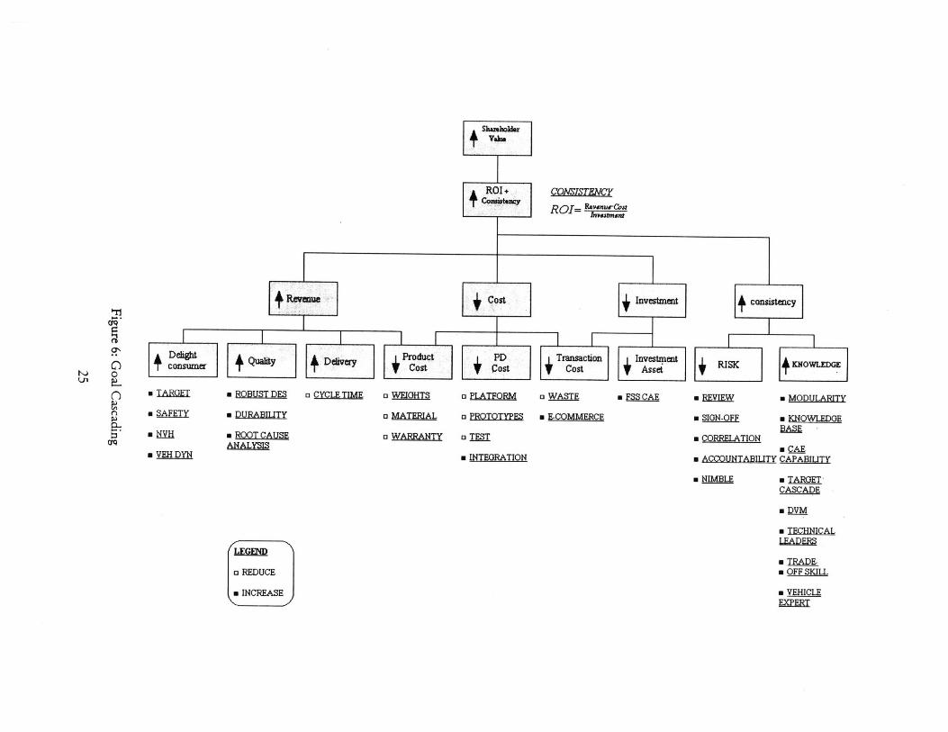
Figure 6 below depicts a goal cascading process and CAE contribution. The ultimate goal of the vehicle
manufacturers is to increase shareholder value over time. This in turns means increasing the return on
investment (ROI) consistently. Consistency is important to long term shareholder and it can be achieved by
having a process to reduce the risk and increasing knowledge. To increase (ROI), the VM needs to increase
revenue, reduce cost and reduce investment. Further cascading down in the diagram in order to increase
revenue, the VM need to increase customer delight, quality, delivery and reduce cost. To reduce cost, the VM
needs to reduce product cost, development cost and transaction cost in conducting outsourcing. To reduce
investment, the VM could reduce investment asset along with transaction cost.
In outsourcing a commodity, the VM are focusing on reducing cost and reducing investment by having the
suppliers spending their capital dollars in tooling, design and development. These costs are to be rolled up in
variable piece cost. By setting up this way, suppliers will share the risk on market share. The lower the
product market share the higher the risk suppliers will not have enough product volume to recover fixed
investment. This is an emerging issue in automotive supplier chain management.
24
+ROIROI= Revanu-Can
consistzncy
RIPSK KOWLEDGE
* REVIEW . MODULARITY
" SIGN-OFF * KNOWLEDGE
" CORRELATIONm CAE
* ACCOUNTABILITY CAPABILJTY
* NIMBLE m TARGET-CASCADE
" DVM
" TECHNICALLEADERS
" TRADE-" OFF SKILL
" VEHICLEEXPERT
C on nvestment
Tnsactn investmnt
Qi PLATFORM a WASTE * FSS CAE
TERIAL a PROTOTYPES E-COMMERCE
AiRRANTY aTES
m INTEGRATION
+eeu~1.
cfQ
'-1
C)k.~ 0ul
C-)C)
a CYCL TIME
+Quaay.
" ROBUST DES
" DURABILITY
" ROOT CAUSEANALYSIS
" TARGET
" SAFETY
m H
LEGEND
a REDUCE
* INCREASE
i
M! i
3.3 CAE Value
3.3.1 Uniqueness about CAE management
An often-raised question when dealing with CAE outsourcing is "what is unique about CAE that
outsourcing it requires special attention?". The followings are review of CAE overall values:
* Value ofCAE is imbedded within the PD therefore it is hard to measure. CAE transforms information.
Management of CAE therefore needs to understand intangible values of CAE and be able to
communicate it with upper management in securing investments so that CAE investment will not
be viewed as additional cost for the design.
* CAE value in managing nsk and knowledge are not a pparent although CAE supports all five goals of
product development: quality, cost, speed, risk and knowledge. These two values however are
unique to CAE. Management of CAE therefore needs to understand these two particular intangible
values of CAE. For example, the difference between CAD and CAE is that CAE deals with
behavior model of the design while CAD deals with the geometry of design. CAE is a living
knowledge while CAD is a "frozen knowledge" model.
" CAE quality verifcation is a unique challenge. Unlike CAD model that could be verified through
dimensionality study, CAE model bears physical properties and constraints that processed by people
upstream (material property, road load, constraints). The potential for modeling error is greater with
CAE model. Also for CAE analysis, since it is done upfront to guide CAD designs, no hardware
available for correlation. The use of CAE therefore needs special management attention in terms of
using appropriate CAE capability and confidence levels to impact design decision effectively.
.26
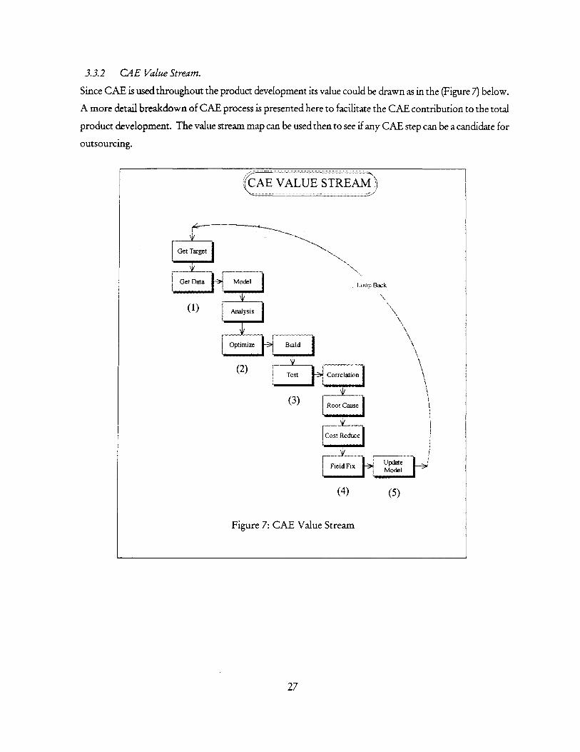
3.3.2 CAE Value Stream.
Since CAE is used throughout the product development its value could be drawn as in the (Figure 7) below.
A more detail breakdown of CAE process is presented here to facilitate the CAE contribution to the total
product development. The value stream map can be used then to see if any CAE step can be a candidate for
outsourcing.
27
CEVALUE STREAM
Get Target
tGet Data Model Loop Back
() Analysis
(1))
(2) s Correlation
(3) Root
(4) (5)
Figure 7: CAE Value Stream
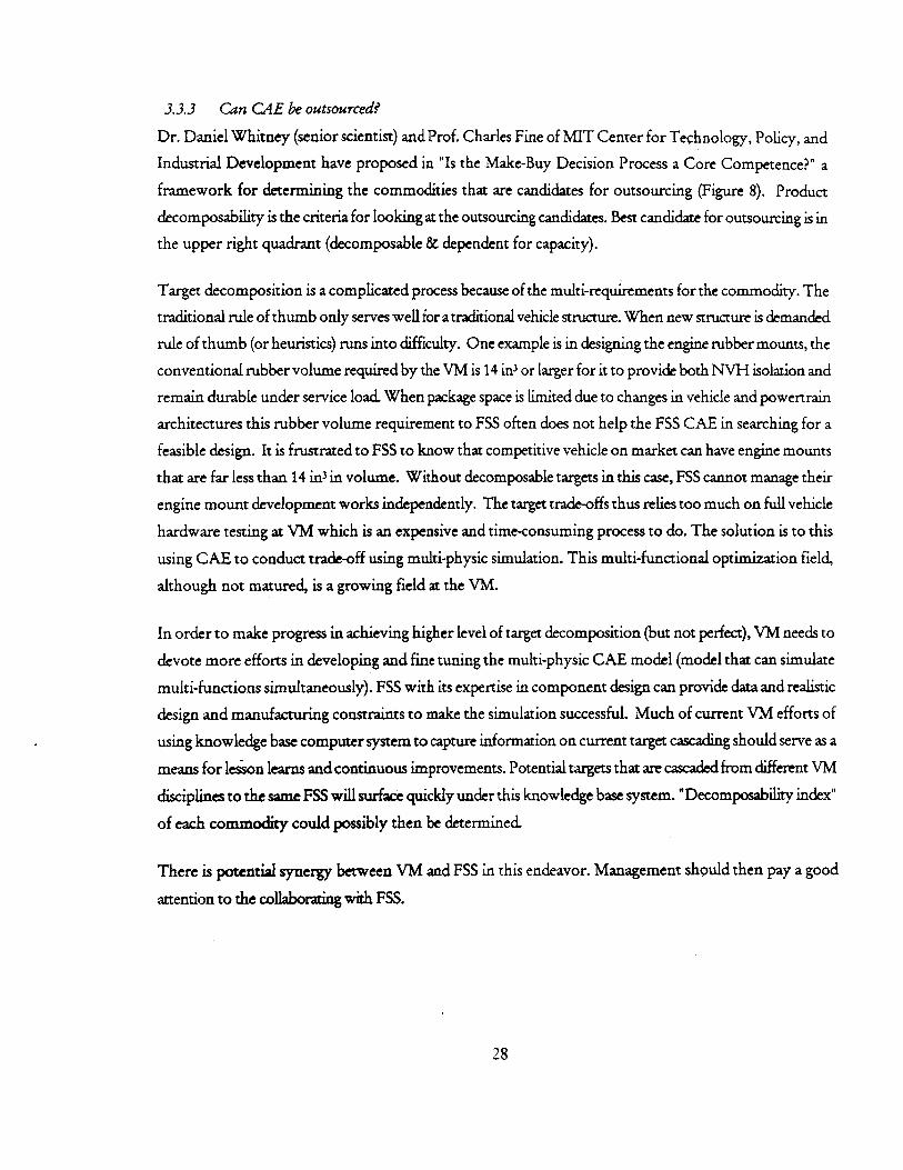
3.3.3 Can CAE be outsourced?
Dr. Daniel Whitney (senior scientist) and Prof. Charles Fine of MIT Center for Technology, Policy, and
Industrial Development have proposed in "Is the Make-Buy Decision Process a Core Competence?" a
framework for determining the commodities that are candidates for outsourcing (Figure 8). Product
decomposability is the criteria for looking at the outsourcing candidates. Best candidate for outsourcing is in
the upper right quadrant (decomposable & dependent for capacity).
Target decomposition is a complicated process because of the multi-requirements for the commodity. The
traditional rule of thumb only serves well for a traditional vehicle structure. When new structure is demanded
rule of thumb (or heuristics) runs into difficulty. One example is in designing the engine rubber mounts, the
conventional rubber volume required by the VM is 14 in3 or larger for it to provide both NVH isolation and
remain durable under service load. When package space is limited due to changes in vehicle and powertrain
architectures this rubber volume requirement to FSS often does not help the FSS CAE in searching for a
feasible design. It is frustrated to FSS to know that competitive vehicle on market can have engine mounts
that are far less than 14 in in volume. Without decomposable targets in this case, FSS cannot manage their
engine mount development works independently. The target trade-offs thus relies too much on full vehicle
hardware testing at VM which is an expensive and time-consuming process to do. The solution is to this
using CAE to conduct trade-off using multi-physic simulation. This multi-functional optimization field,
although not matured, is a growing field at the VM.
In order to make progress in achieving higher level of target decomposition (but not perfect), VM needs to
devote more efforts in developing and fine tuning the multi-physic CAE model (model that can simulate
multi-functions simultaneously). FSS with its expertise in component design can provide data and realistic
design and manufacturing constraints to make the simulation successful. Much of current VM efforts of
using knowledge base computer system to capture information on current target cascading should serve as a
means for lesson learns and continuous improvements. Potential targets that are cascaded from different VM
disciplines to the same FSS will surface quickly under this knowledge base system. "Decomposability index"
of each commodity could possibly then be determined.
There is potential synergy between VM and FSS in this endeavor. Management should then pay a good
attention to the collaborating with FSS.
28
Figure 8: Matrix of Dependency and Outsourcing
DEPENDENT FOR KNOWLEDGE
A POTENTIAL OUTSOURCING
TRAP
YOUR PARTNERS COULD
SUPLLANT YOU. THEY HAVE AS
MUCH OR MORE KNOWLEDGE
AND CAN OBTAIN THE SAME
ELEMENTS YOU CAN
WORST OUTSOURCING SITUATION
YOU DON'T UNDERSTAND WHAT
YOU ARE BUYING OR HOW TO
INTEGRATE IT. THE RESULT
COULD BE FAILURE SINCE YOU
WILL SPEND SO MUCH TIME ON
REWORK OR RETHINKING
DEPENDENT FOR CAPACITY
I BEST OUTSOURCING OPPORTUNITY
YOU UNDERSTAND IT, YOU CAN PLUG
IT INTO YOUR PROCESS OR PRODUCT,
AND IT PROBABLY CAN BE OBTAINED
FROM SEVERAL SOURCES. IT PROBABLY
DOES NOT REPRESENT COMPETITTVE
ADVANTAGE IN AND OF ITSELF.
BUYING IT MEANS YOU SAVE
ATTENTION TO PUT INTO AREAS
WHERE YOU HAVE COMPETITIVE
ADVANTAGE, SUCH AS INTEGRATING
OTHER THINGS
CAN LIVE WITH OUTSOURCING
YOU KNOW HOW TO INTEGRATE THE
ITEM SO YOU MAY RETAIN
COMPETITIVE ADVANTAGE EVEN IF
OTHERS HAVE ACCESS TO THE SAME
ITEM.
The above matrix will be used in the following CAE outsourcing analysis to determine what CAE step is a
candidate and a not candidate of outsourcing.
29
0
U
I0
'
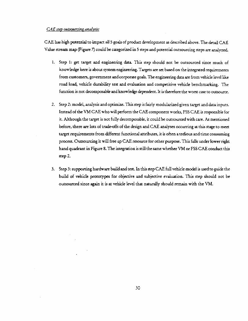
CAE step outsourcing analysis:
CAE has high potential to impact all 5 goals of product development as described above. The detail CAE
Value stream map (Figure 7) could be categorized in 5 steps and potential outsourcing steps are analyzed.
1. Step 1: get target and engineering data. This step should not be outsourced since much of
knowledge here is about system engineering. Targets are set based on the integrated requirements
from customers, government and corporate goals. The engineering data are from vehicle level like
road load, vehicle durability test and evaluation and competitive vehicle benchmarking. The
function is not decomposable and knowledge dependent. It is therefore the worst case to outsource.
2. Step 2: model, analysis and optimize. This step is fairly modularized given target and data inputs.
Instead of the VM CAE who will perform the CAE component works, FSS CAE is responsible for
it. Although the target is not fully decomposable, it could be outsourced with care. As mentioned
before, there are lots of trade-offs of the design and CAE analyses occurring at this stage to meet
target requirements from different functional attributes, it is often a tedious and time consuming
process. Outsourcing it will free up CAE resource for other purpose. This falls under lower right
hand quadrant in Figure 8. The integration is still the same whether VM or FSS CAE conduct this
step 2.
3. Step 3: supporting hardware build and test. In this step CAE full vehicle model is used to guide the
build of vehicle prototypes for objective and subjective evaluation. This step should not be
outsourced since again it is at vehicle level that naturally should remain with the VM.
30
CAE to put out fires
UpstreamCAE to avoid fires
Program Time - ProductionStart
Figure 9: Upfront CAE
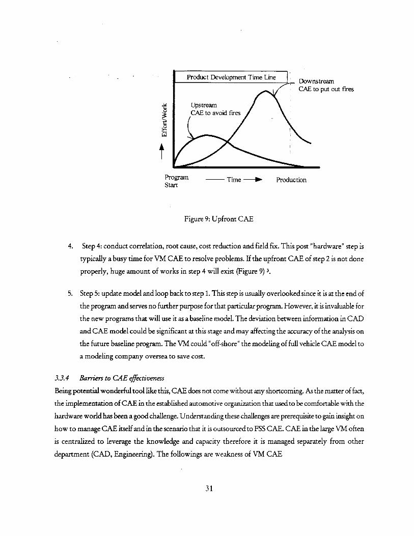
4. Step 4: conduct correlation, root cause, cost reduction and field fix. This post "hardware" step is
typically a busy time for VM CAE to resolve problems. If the upfront CAE of step 2 is not done
properly, huge amount of works in step 4 will exist (Figure 9) 3.
5. Step 5: update model and loop back to step 1. This step is usually overlooked since it is at the end of
the program and serves no further purpose for that particular program. However, it is invaluable for
the new programs that will use it as a baseline model. The deviation between information in CAD
and CAE model could be significant at this stage and may affecting the accuracy of the analysis on
the future baseline program. The VM could "off-shore" the modeling of full vehicle CAE model to
a modeling company oversea to save cost.
3.3.4 Barriers to CAE effectiveness
Being potential wonderful tool like this, CAE does not come without any shortcoming. As the matter of fact,
the implementation of CAE in the established automotive organization that used to be comfortable with the
hardware world has been a good challenge. Understanding these challenges are prerequisite to gain insight on
how to manage CAE itself and in the scenario that it is outsourced to FSS CAE. CAE in the large VM often
is centralized to leverage the knowledge and capacity therefore it is managed separately from other
department (CAD, Engineering). The followings are weakness of VM CAE
31
Product Development Time LineDownstream
1. CAE modeling time isa botteneck. This is aggravated by the interoperability problem between CAD
and CAE. Briefly this is the problem that CAD deliverables information does not 'fit' into the usage
of downstream CAE. This is often due to different organizations that manage CAD and manage
CAE. Outsourcing to FSS, CAE modeling is usually taken care by the same organization. There is a
strong incentive for FSS to make the process works smoothly to minimize cost and delays.
2. CAE acceptance is inconsistent. In the past, VM CAE has been not able to fully integrate into the PD
process. This is due to organization issues similar to the issue of CAD/CAE organization
mentioned above. The inconsistent acceptance of CAE recommendation also stemmed from the
fact that CAE quality is also inconsistent. The complexity of CAE model size sometimes hinders the
rework discovery process. The author therefore proposes a quality modeling check process as a
remedy for problem (see page 63).
3. CAEis not implementedupfrontenough. Too much of "throw over the walls" engineering still occurring
between CAD and CAE. A consistent theme of organization problem is seen again here. Enablers
that tie CAD / CAE together, in the form of integrated CAE/CAD package, are beginning to
emerge that could help bridging the culture gap between designers and analysts. Upfront CAE
values (problem prevention) are harder to be realized than at downstream stage where there are
problems and CAE can be a solution.
4. CAE capabilitycoverage is not complete. There are still a variety of vehicle phenomenathat CAE vehicle
system model does not address. The limit is due to technology and human resource. Therefore, it is
much harder to affect the design with partial solution. This creates difficulties if decomposing the
system target to component target.
32
4 CAE OUTSOURCING
4.1 About Outsourcing
Outsourcing is not just a management fad:
Unlike "instant coffee" management tools of "down sizing" and "re-engineering" that are applied in away
not relevant to the company problem. Outsourcing is a long-term strategic management tool that requires
cares in make/buy decision, determining of core competency and the management of the collaboration
process. The following views are appropriate and applicable to the automotive product development
organization.
4.1.1 Outsourcing is "re-organization"
Outsourcing is the shifting boundaries of organizations
The shifting occurs to take advantage of "specialization" among partners. In outsourcing, organization is "re-
drawn" not reduced. The internal staff becomes external staff and the focus is on the growth of business
instead of maintaining it.
4.1.2 Outsourcing is about "specialization"
Specialization is nothing more than the division of works among the specialists. The VM in this case is the
specialist in integration instead of being a generalist coordinating the tasks. Specialization benefits derived
based on the principle of "relative effectiveness". For example, even though the company can do both two
activities A and B better than anybody else, it still should outsource the lesser value task B to use the time
and resource for producing a more value task A. Before the "re-drawn" boundary of the organization occurs
one needs to know how to determine "core competency" for long term development as a competitive
advantages and which activities will be farmed out. Since outsourcing is about re-organization to ensure its
success, all traditional good principle of management needs to apply: setting goals, monitoring performance,
take corrective actions and creative environment for growth are still applicable to outsourcing however, the
form and format for doing that have changed.
4.1.3 Outsourcing is a "strategic" management tool
Outsourcing is nothing more and nothing less than a management tool. It is used to achieve specific
management objectives. There is no right and wrong, but there is right and wrong within the context of what
the organization is trying to accomplish. Outsourcing is management and not "abdication" and therefore
requires proactive management. The management style however is very different from the style of managing
internal organization.
33
1. It is also important to distinguish between outsourcing and contracting. In outsourcing the company
gives up the control of the "how" and focuses only on the "what" of deliverable. Thus it demands a
new style of management and new skill sets. Dr. Michael Useem of Wharton refers to as leading
laterally as opposed to managing down.
34
4.2 Outsourcing Strategy
4.2.1 FSS process - the drive towards modularity
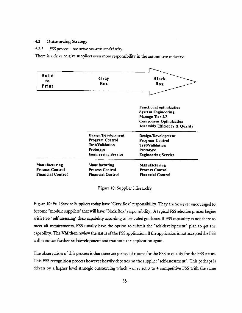
There is a drive to give suppliers even more responsibility in the automotive industry.
Design/Development Design/DevelopmentProgram Control Program ControlTest/Validation Test/ValidationPrototype PrototypeEngineering Service Engineering Service
Manufacturing Manufacturing ManufacturingProcess Control Process Control Process ControlFinancial Control Financial Control Financial Control
Figure 10: Supplier Hierarchy
Figure 10: Full Service Suppliers today have "Gray Box" responsibility. They are however encouraged to
become "module suppliers" that will have "Black Box" responsibility. A typical FSS selection process begins
with FSS "self assessing" their capability according to provided guidance. If FSS capability is not there to
meet all requirements, FSS usually have the option to submit the "self-development" plan to get the
capability. The VM then review the status of the FSS application. If the application is not accepted the FSS
will conduct further self-development and resubmit the application again.
The observation of this process is that there are plenty of rooms for the FSS to qualify for the FSS status.
This FSS recognition process however heavily depends on the supplier "self-assessment". This perhaps is
driven by a higher level strategic outsourcing which will select 3 to 4 competitive FSS with the same
35
commodity to get different outsource contracts for different vehicle programs. The strategy here is to keep
FSS competing with each other to manage risk and reducing cost.
4.2.2 CAE FSS process
VM CAE usually has no inputs into the selection process of FSS. They are informed by the VM engineering
of the selected FSS suppliers and start the writing statement of work process to detail the CAE requirements.
An unstructured collaboration process begins and the results usually are surprises.
4.3 FSS CAE capability
4.3.1 Classification
The FSS CAE capability could be classified as of 3 levels:
1. No capability: These FSS rely on independent CAE consultant companies for CAE services. It is
done mostly to comply with the request from the VM CAE. Their commodity tends to be small like
engine mount, engine mount bracket, knuckles ... The result is that FSS does not engage FEA into
the development process. It usually is done at the end for confirmation. The quality of those
services varies from vendor to vendor. Since there is no direct contact between the VM CAE and
consultant CAE, most of the deliverables do not meet the form, fit, function and time requirements
(FFFT). The results are many surprises and reworks.
2. Developing capability: These FSS have FEA group in house and have scale due to their size of
commodity and they are working for multiple VM. Such commodities are truck frame, instrument
panel, seats ... they tend however to centralize the internal CAE group to leverage the expertise and
productivity among CAE analysts. They are in a growing pain period that develops standard
procedure and CAE structure. This FSS CAE growing period is similar to the long period that most
VM CAE have gone through in the past. Yet there is little attention on a strategic level for CAE
cooperation among the VM CAE and FSS CAE groups. CAE analysts are sitting with their peers
while engineers and designers are together and located at the customer site. There is again problem
with this arrangement because CAE requirements from the VM are still relative new to them.
3. Developed capdbiity These FSS have experiences in FEA and FEA has been part of the business for
sometimes. They are mega suppliers that have volume and a verity of products. In some cases they
are pioneering the re-engineering process of "up-front analysis" one step further than even the VM
CAE.
36
4.3.2 Outsourcing Benefits
Outsourcing a portion of CAE to FSS provides the following immediate benefits
1. CAE modeling time. Historically, CAE component modeling has been a bottleneck in the CAE
process. It is a laborious and time consuming job that hardly appropriate for the level of skills that
typical CAE analysts at the VM who possess Ph.D. and M.S. level in engineering. Hence, by
outsourcing this CAE modeling the VM CAE can better utilize its workforce skill and at the same
time increasing their job satisfaction. Re-organization in the form of outsourcing in this case can
solve a persistent problem of maintaining accountability in quality model within the VM CAE
internal organization. Now there is an exclusive entity, the FSS CAE that is accountable for the
modeling work. The challenge is to give clear specification for model quality and a quick and easier
way for quality verification (see 6.1.1).
2. Better product: It is easier for people in the same organization like the FSS to have incentive to work
together. The VM CAE does not have to push them for the developing of the product design. The
challenge here is to have FSS CAE realizing the dual responsibility of supporting also the VM CAE
in the quest for vehicle system model and analysis.
3. Forcing the VM CAE to be more explicit about the CAE requirements. This task would not be
accomplished easily and seriously in the exclusive VM CAE organization. The reason is that they
can work in the "interactive" mode and see the need to write down requirement as something of
non-value added. There is a great potential of leveraging FSS CAE for their inputs into the writing
of the requirements since FSS is also responsible for testing. The process of CAE correlation by FSS
could help modifying the writing of CAE requirements.
4.3.3 Outsourcing Costs:
Besides the obvious cost could be attributed due to outsourcing, many other un-anticipated often hidden
transaction costs associated with the project
1. Assessment cost: there is time spent to prepare, visit and conducting assessment suppliers. This effort
is perhaps the biggest discouragement for VM CAE to get involved and thus rather leave this work
for the engineering community, which does not have good CAE knowledge. The danger for VM
CAE not involving in this phase is that there will be lots of surprise down the road.
2. Writing requirement statement of work: there is elaborate time spent to prepare and review the
document with FSS and other internal group. There is also a natural tendency for FSS to accept
37
whatever written in SOW to make good impression about FSS capability in hope that it could
develop these skills quickly. The different types of organization also make the gathering of
specification a bit challenging. For example, if the VM CAE is organized according to functions
with different groups in charge of their separate requirement documents it could take sometime to
gather and sort out the conflict. More important and often ignored is that there is a risk associated
with giving out standard and method that have been developed in house with years of investment.
It is arguably that they are non-competitors and working as our extended enterprise. Nevertheless,
almost all suppliers are working for all automotive competitors as part of their business strategy.
3. Collaborating: the cost of shadow engineering is likely evident as the VM cannot let go completely all
CAE related to FSS. This is so for several reasons. For years, no design and analysis works are
given to FSS; a learning curve and resource issue therefore exists in setting up and finding qualified
CAE analysts to work for. Secondly, VM are still responsible to the final consumers as they
continue to build trust through brand management. There is a high degree of interactions of
different functions affecting the design. Some functions are currently only effective at vehicle
evaluation such as safety, vehicle dynamics.
4. Veriwation: since VM retain the final verification task, much of reworks and thus costs are incurred
at this stage, as FSS CAE often under time pressure could possibly deliver unfinished CAE
product to VM.
4.4 Issues in Outsourcing CAE
4.4.1 Reworks
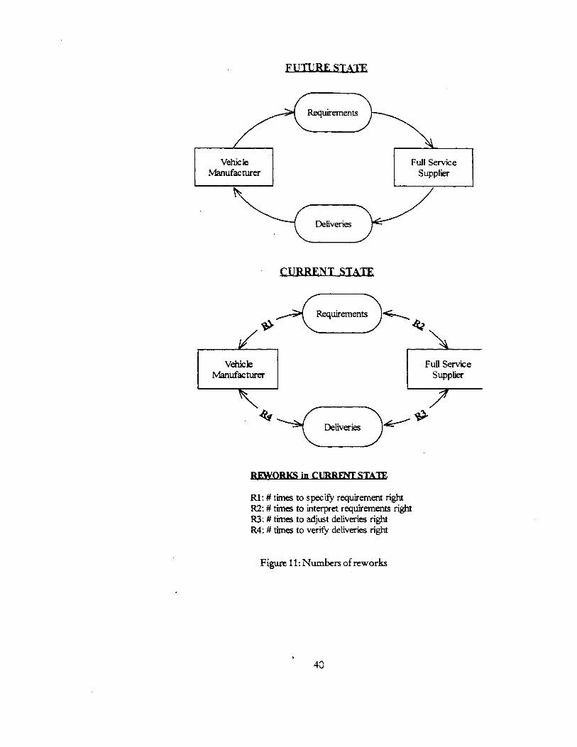
(Figure 11) below shows "Future State" depicting an ideal world of FSS management, the VM will write
requirements, passing them along to FSS. Full Service Suppliers then performs the works and deliver result
back to the VM. The VM verify that they meet the requirement and ending the loop. There is no reworks,
obsolete works, non-quality works.
The Current State however, to be realistic, VM often alter requirements due to unforeseen circumstances
such as government regulation changes or due to the lack of a full ability to cascade down targets. The
requirements when written down could be possibly mis-interpreted by the FSS a few times due to the
unfamiliarity with VM product development system, example of this is that a seat supplier could interpret
seat natural frequency with a rigid boundary condition, while what the VM want is a flexible boundary
condition having the seat mounted on the floor. FSS can take more than one time to deliver the results due
to reworks. Example of this could be that FSS CAE do not have enough and updated information or there is
defection to the execution of their CAE works. The deliverables could be rejected due to VM verification
38
process. Example of this could be that VM and FSS CAE are using two different CAE commercial
programs that give two different results.
Not much information is accumulated as of how many times the reworks are observed. If the situation is out
of control, the VM CAE usually conduct shadow engineering, start checking the model and results from FSS
every time.
39
Requirements
Vehic le FulH ServiceManufacturer Supplier
Deliveries
Requirements <
VehicleManufacturer
Full ServiceSupplier
Deliveries
REWORKS in CURRENT STATE
RI: # times to specify requirement rightR2: # times to interpret requirements rightR3: # times to adjust deliveries rightR4: # times to verify deliveries right
Figure 11: Numbers of reworks
40
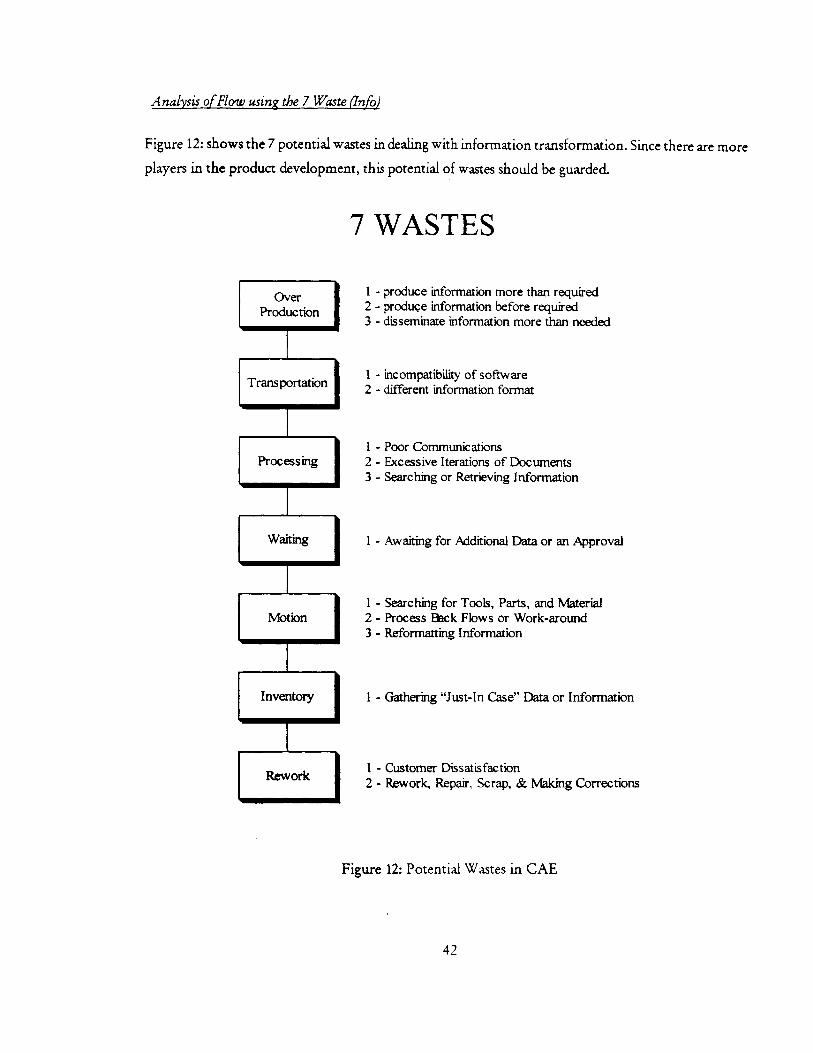
4.4.2 Potential Wastes created
The more players, the more mishaps could occur in the collaborating process. One can view this
collaborating effort with FSS as an optimization of flow 4. Similarly as in the Lean manufacturing process -
the 7 waste principles have been studied and reapplied to product development. It could be used to apply in
CAE outsource management process.
41
A nalysis of Flow using the 7 Waste (Info)
Figure 12: shows the 7 potential wastes in dealing with information transformation. Since there are more
players in the product development, this potential of wastes should be guarded.
7 WASTES
1 -2-3-
OverProduction
Transportation
Processing
Waiting
Motion
Inventory
Rework
produce information more than requiredproduce information before requireddisseminate information more than needed
1 - incompatibility of software2 - different information format
1 -2-3-
Poor CommunicationsExcessive Iterations of DocumentsSearching or Retrieving Information
1 - Awaiting for Additional Data or an Approval
1 -2-3-
Searching for Tools, Parts, and MaterialProcess Back Flows or Work-aroundReformatting Information
Schedule management Packaging study Solve design problem
Customer contact Manufacturing assessment Correlate to test
Supplier management Calibrate computer model
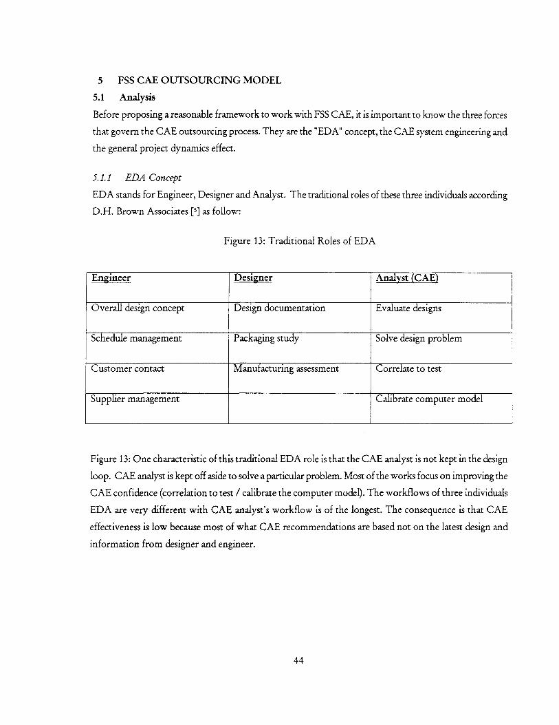
Figure 13: One characteristic of this traditional EDA role is that the CAE analyst is not kept in the design
loop. CAE analyst is kept off aside to solve a particular problem. Most of the works focus on improving the
CAE confidence (correlation to test / calibrate the computer model). The workflows of three individuals
EDA are very different with CAE analyst's workflow is of the longest. The consequence is that CAE
effectiveness is low because most of what CAE recommendations are based not on the latest design and
information from designer and engineer.
44
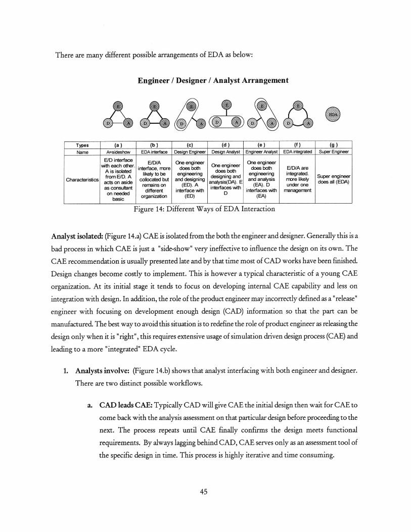
There are many different possible arrangements of EDA as below:
Engineer / Designer / Analyst Arrangement
Types (a ) (b ) (c) (d ) (e ) (f ) (g )Name A=sideshow EDA interface Design Engineer Design Analyst Engineer Aalyst EDA integrated Super Engineer
E/D interface E/D/A One engineer One engineer.each other. interface, more does both One engineer does both E/D/A are
o likely to be engineering des engineering integrated. Su engineerCharacteristics acts on aside collocated but and designing anaigDA). E and analysis rmore likely does all (EeA)
a o remains on (ED). A inre (EA). D under one
on needed different interface wth D interfaces wth management
basic organization (ED) (EA)
Figure 14: Different Ways of EDA Interaction
Analyst isolated: (Figure 14.a) CAE is isolated from the both the engineer and designer. Generally this is a
bad process in which CAE is just a "side-show" very ineffective to influence the design on its own. The
CAE recommendation is usually presented late and by that time most of CAD works have been finished.
Design changes become costly to implement. This is however a typical characteristic of a young CAE
organization. At its initial stage it tends to focus on developing internal CAE capability and less on
integration with design. In addition, the role of the product engineer may incorrectly defined as a "release"
engineer with focusing on development enough design (CAD) information so that the part can be
manufactured. The best way to avoid this situation is to redefine the role of product engineer as releasing the
design only when it is "right", this requires extensive usage of simulation driven design process (CAE) and
leading to a more "integrated" EDA cycle.
1. Analysts involve: (Figure 14.b) shows that analyst interfacing with both engineer and designer.
There are two distinct possible workflows.
a. CAD leads CAE: Typically CAD will give CAE the initial design then wait for CAE to
come back with the analysis assessment on that particular design before proceeding to the
next. The process repeats until CAE finally confirms the design meets functional
requirements. By always lagging behind CAD, CAE serves only as an assessment tool of
the specific design in time. This process is highly iterative and time consuming.
45
b. CAE leads CAD: This is an appropriate way for "form follows function" design. A
higher level of CAE skill and capability are neededto make it work. To precede CAD, CAE
needs to do model without the reliance on detail CAD and still able to produce CAD
specific recommendation. There are currently several strategies in the industry today
2. Dual Roles: (Figure 14.c-e) shows different combinations of two individual functions into one.
These types of arrangements are seen at supplier companies. Among those the type (d) is a new
trend with CAD system starts handling the preliminary CAE works. At those companies the analysis
work is re-categorized into 3 different levels:
i. First Pass Analyses: are those analyses that simple enough for designer to handle
while designing. The tool from Ansys " Design Space" facilitates the process by
allowing designer to perform basic "what if" questions. Such process filters out
bad ideas early before they get through to CAE analyst who will perform the
second level analysis - more complex and time consuming. Loading and boundary
conditions in first pass analysis are simple and directional only. The CAE analysts
help the initial set up.
ii. Sophisticated analyses: are performed by the experience CAE analysts who will
use advance FEA solvers to solve assembly problems and complex loading. At this
stage, the design will be "tuned" instead of throwing back to CAD.
iii. The new problems: are handle by the third level of CAE analysts, the expert
group that set up new methods to increase CAE capability.
Due to its large size of workforce VM have had problem in integrating the three disciplines EDA together.
The VM however can set up a process for EDA engineers to interface among each other (14.b). Unlike VM,
FSS are smaller size and could be able to combine 3 roles into 2 (14.c-e). This reduces the number of
communication links among them. Arrangement 14.f where all EDA are put under one organization
(integrated) is also seen on some of the smaller FSS. The last option of "super EDA" engineer (14.g) simply
is not practical due to the large amount of works required from each individual.
If the engineers and the designers are from FSS as in the full service supplier process, the analyst should be
with FSS as well to keep the EDA cycle as close as possible.
46
The potential problem is that in this arrangement assumption that one CAE analyst from FSS will be equal
to one CAE analyst from the VM is not really true. In the short run this is not the case because VM have a
lot more CAE experience than of the FSS. There is needed shadow engineering to make FSS CAE "smarter"
in getting through the initial learning curve. Therefore, outsourcing CAE requires VM management to pay
attention to the collaboration process and willing to kick in some resource for initial transition. "Spot
contracting" simply would not work.
The long-term benefits of letting FSS performing the CAE analysis are:
" Better communication among EDA cycle since all of them are from the same company they will
have a strong incentive to work together to satisfy their immediate customer (VM) and actively
compete with other suppliers under the free market driver.
* FSS is free to experiment component innovation. Take steering column system commodity for
example, there are multiple design inventions that provide design parameters to achieve NVH
stiffness and safety performance characteristic simultaneously. (Delphi's collapsible steering column
main housing that provides stiffness for NVH. It is constructed with an outer steel tube jacket over
inner stationary steel tube jacket. Sandwiched between the jackets are metal ball bearings. In an
impact, the steering column collapses, the outer jacket slides over the inner one. Ball bearings mark
groves on the jackets to dissipate energy from crash).
5.1.2 System Engineering Concept
The VM is responsible for the target cascading from full vehicle level down to commodity level for FSS.
Regardless if the outsourcing occurs or not, decomposition of target is a necessary condition though my not
be sufficient to effectively improve work efficiency at the component levels. Take steering column system
example, while a majority of NVH targets could be cascaded, safety target may not be able to. The concept
design of the steering column system then has to have "tuning" capability so that design can be changed late
in the design cycle.
Among many ways to cascade NVH targets, NVH modal separation chart is a way to cascade targets. An
example below will illustrate how to cascade NVH target to each supplier.
There are two main sources of NVH vibration excitations into the vehicle that can affect the steering column
vibration (Figure 15). The first is from the powertrain excitation. Engine idle (hot & cold) excitation
frequencies are monitored. For some truck vehicle programs that have multiple powertrain options, the
excitation spectrum is very dense and makes the modal separation effort more difficult.
47
The second source of excitation comes from the resonance of other systems. Suspension hop and tramp
frequencies, body front-end torsion and bending modes ... in design the steering column, one wish to avoid
these frequencies all together.
Benchmark data from "image" vehicle is used to determine the range of frequency target for the steering
column in vehicle position and on subsystem rigid bedplate. All frequencies at vehicle level are mapped into
the following Modal Separation chart (Figure 17).
After selecting the reasonable target for steering column system in vehicle position (30 -35 Hz) for example,
a target cascading process is conducted.
o
Figure 15: Steering Column
There are two approaches to achieve the target:
1. Based on benchmark. An actual vehicle that has successfully achieved the desired steering column
natural frequency range of interest 30 - 35 Hz for example, is decomposed into system, subsystem
and components levels. The stiffness of each subsystem is measured and set as target.
48
I --
In VehicleWhesU/ColumnelVertical Response
30 -36 Hz
Wheel Body., Column :Crosscar,
-- Beam
11nt9rfaCe(Attachments)
Figure 16: Wheel/Column Vertical Response
(Figure 16) shows the components and interfaces among them that contribute to the total stiffness of