79
BRKEWN-2019 Managing the mobile device wave: Best Practices
BRKEWN-2019
Managing the mobile device wave: Best Practices
© 2011 Cisco and/or its affiliates. All rights reserved. Cisco PublicBRKEWN-2019 2
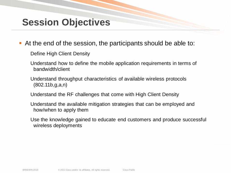
At the end of the session, the participants should be able to:Define High Client Density
Understand how to define the mobile application requirements in terms of bandwidth/client
Understand throughput characteristics of available wireless protocols (802.11b,g,a,n)
Understand the RF challenges that come with High Client Density
Understand the available mitigation strategies that can be employed and how/when to apply them
Use the knowledge gained to educate end customers and produce successful wireless deployments
Session Objectives
© 2011 Cisco and/or its affiliates. All rights reserved. Cisco PublicBRKEWN-2019 3
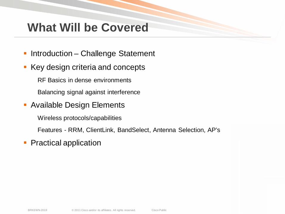
Introduction – Challenge Statement
Key design criteria and conceptsRF Basics in dense environments
Balancing signal against interference
Available Design ElementsWireless protocols/capabilities
Features - RRM, ClientLink, BandSelect, Antenna Selection, AP’s
Practical application
What Will be Covered
© 2011 Cisco and/or its affiliates. All rights reserved. Cisco PublicBRKEWN-2019 4
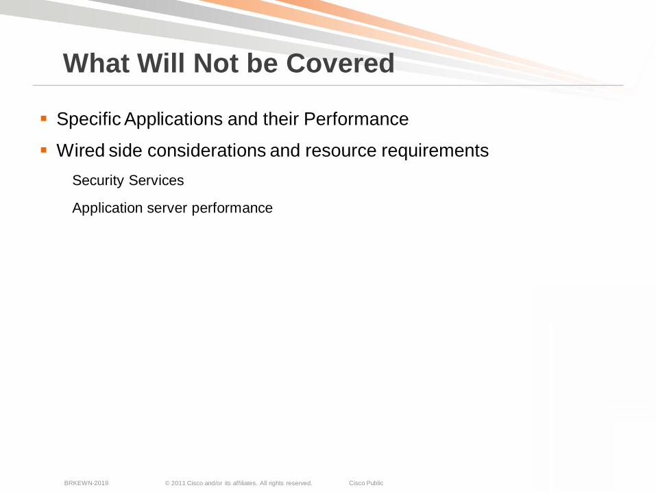
Specific Applications and their Performance
Wired side considerations and resource requirementsSecurity Services
Application server performance
What Will Not be Covered
© 2011 Cisco and/or its affiliates. All rights reserved. Cisco PublicBRKEWN-2019 5
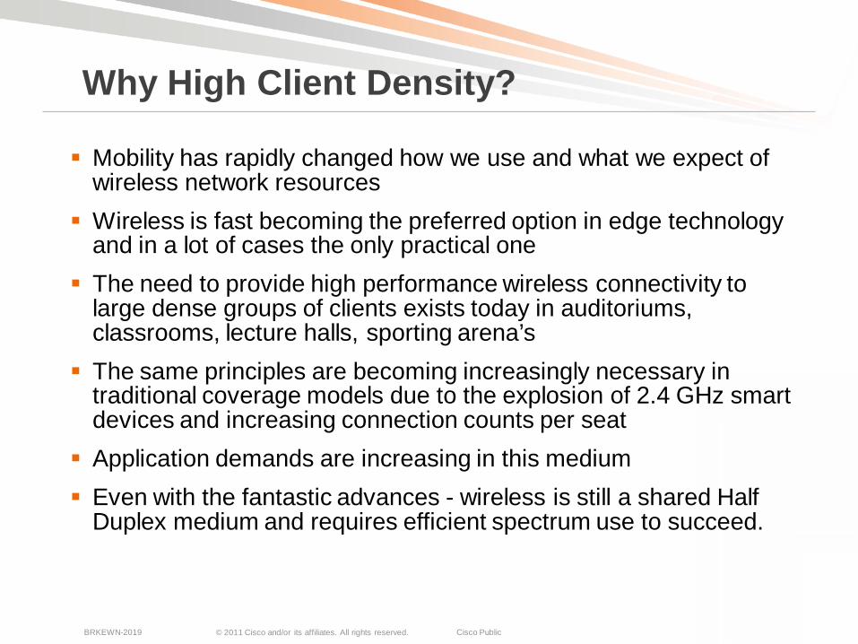
Mobility has rapidly changed how we use and what we expect of wireless network resources
Wireless is fast becoming the preferred option in edge technology and in a lot of cases the only practical one
The need to provide high performance wireless connectivity to large dense groups of clients exists today in auditoriums, classrooms, lecture halls, sporting arena’s
The same principles are becoming increasingly necessary in traditional coverage models due to the explosion of 2.4 GHz smart devices and increasing connection counts per seat
Application demands are increasing in this medium Even with the fantastic advances - wireless is still a shared Half
Duplex medium and requires efficient spectrum use to succeed.
Why High Client Density?
© 2011 Cisco and/or its affiliates. All rights reserved. Cisco PublicBRKEWN-2019 6
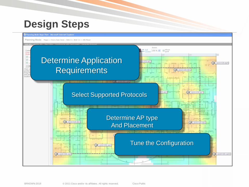
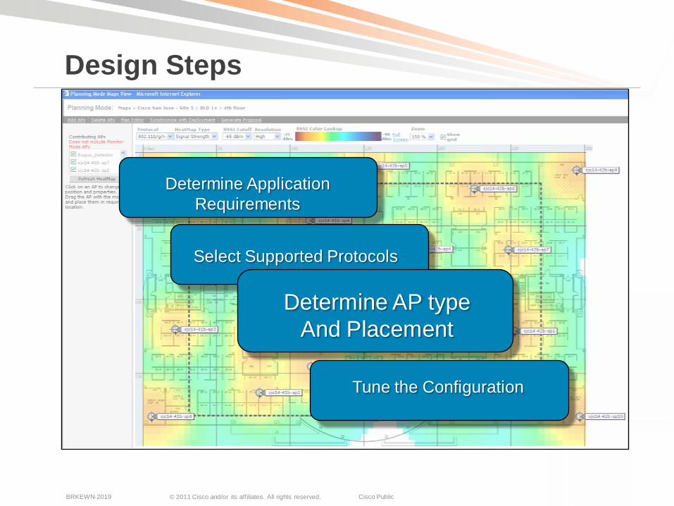
Design Steps
Determine ApplicationRequirements
Select Supported Protocols
Determine AP typeAnd Placement
Tune the Configuration

© 2011 Cisco and/or its affiliates. All rights reserved. Cisco PublicBRKEWN-2019 7
802.11, like Ethernet, is a shared medium
Aggregate throughput is the total bandwidth shared by all users in a cell
Generally, the larger the cell, the more users in the cell
Greater per user throughput means smaller cells and more access points for a given area
How many users per access point?What’s the aggregate throughput of the access point?
On average, what amount of per user throughput do you need to provide?
Aggregate and Per-User Throughput
© 2011 Cisco and/or its affiliates. All rights reserved. Cisco PublicBRKEWN-2019 8
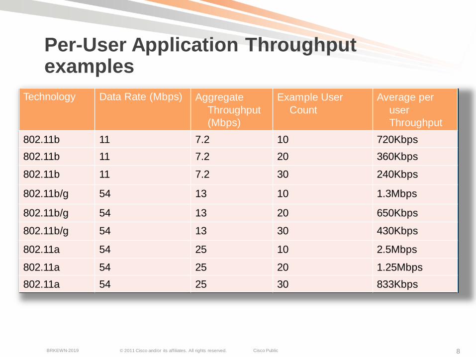
Per-User Application Throughputexamples
Technology Data Rate (Mbps) Aggregate Throughput (Mbps)
Example User Count
Average per user Throughput
802.11b 11 7.2 10 720Kbps802.11b 11 7.2 20 360Kbps
802.11b 11 7.2 30 240Kbps
802.11b/g 54 13 10 1.3Mbps
802.11b/g 54 13 20 650Kbps
802.11b/g 54 13 30 430Kbps
802.11a 54 25 10 2.5Mbps
802.11a 54 25 20 1.25Mbps802.11a 54 25 30 833Kbps

© 2011 Cisco and/or its affiliates. All rights reserved. Cisco PublicBRKEWN-2019 9
What about HT20 rates?
10 15 20 25 30 35 40 45 500
2
4
6
8
10
12
14
Number of clients
Thr
ough
put
of p
er c
lient
, M
bps
Throuput of mixed 11a and 11n clients, with RTS-CTS
100% 11n75% 11n50% 11n25% 11n100% 11a
What is your expected mix of HT20 to legacy clients?
Few have the luxury of establishing and maintaining a fixed ratio – be sure
The delta between 100% 802.11n clients and 100% legacy 802.11a clients is a 312% increase/decrease
A 50/50 mix however drops that advantage to 34% increase
As user density increases the spread narrows

© 2011 Cisco and/or its affiliates. All rights reserved. Cisco PublicBRKEWN-2019 10
Application – by use case
Throughput – Nominal
Web - Casual 500 Kbps
Web - Instructional 1 Mbps
Audio - Casual 100 Kbps
Audio - instructional 1 Mbps
Video - Casual 1 Mbps
Video - Instructional 2-4 Mbps
Printing 1 Mbps
File Sharing - Casual 1 Mbps
File Sharing - Instructional 2-8 Mbps
Online Testing 2-4 Mbps
Device Backups 10-50 Mbps
How Much Bandwidth is Required?Often, less than you’d think
It is most likely that you won’t be supporting just one application
Design for the highest bandwidth demand that you intend to support
What you really need here is the minimum acceptable throughput that the application will require
It is advisable to measure this yourself on multiple platforms -manufacturer/supplier numbers are good – but Trust and Verify is always a better career bet.
Multiply this number by the number of connections/seats that you need to support
This is the aggregate bandwidth you will require in your space
© 2011 Cisco and/or its affiliates. All rights reserved. Cisco PublicBRKEWN-2019 11
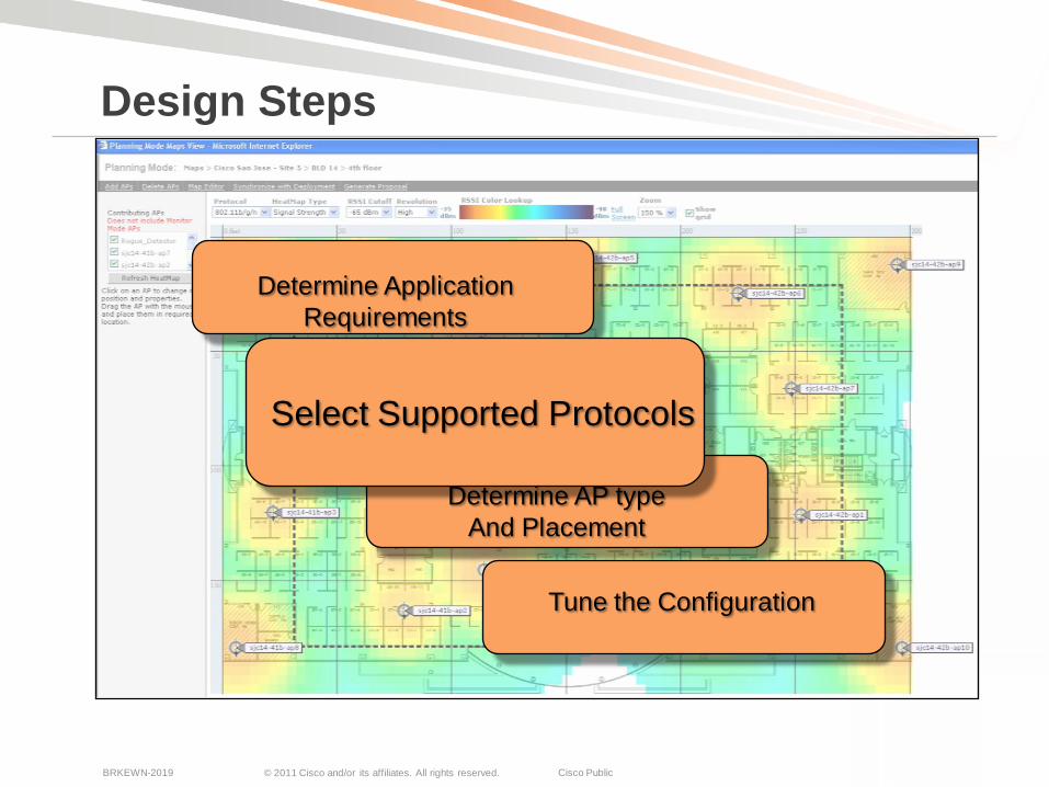
Design Steps
Determine ApplicationRequirements
Determine AP typeAnd Placement
Tune the Configuration
Select Supported Protocols
© 2011 Cisco and/or its affiliates. All rights reserved. Cisco PublicBRKEWN-2019 12
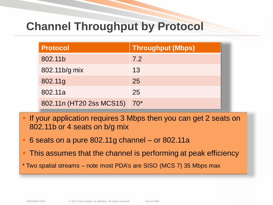
If your application requires 3 Mbps then you can get 2 seats on 802.11b or 4 seats on b/g mix
6 seats on a pure 802.11g channel – or 802.11a
This assumes that the channel is performing at peak efficiency* Two spatial streams – note most PDA’s are SISO (MCS 7) 35 Mbps max
Channel Throughput by Protocol
Protocol Throughput (Mbps)802.11b 7.2 802.11b/g mix 13802.11g 25802.11a 25802.11n (HT20 2ss MCS15) 70*
© 2011 Cisco and/or its affiliates. All rights reserved. Cisco PublicBRKEWN-2019 13
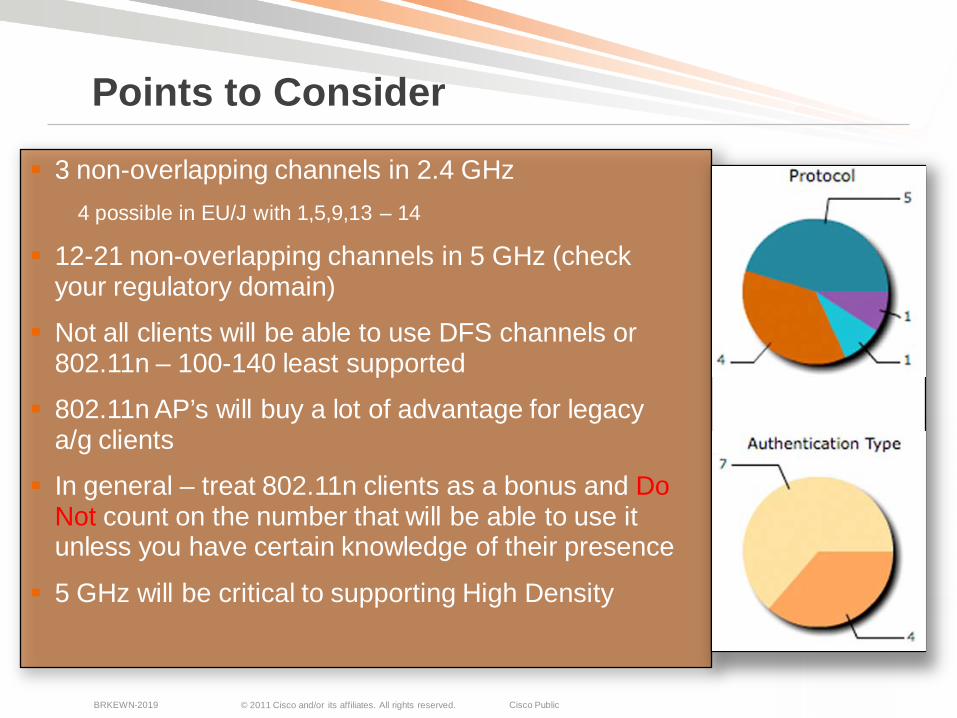
3 non-overlapping channels in 2.4 GHz4 possible in EU/J with 1,5,9,13 – 14
12-21 non-overlapping channels in 5 GHz (check your regulatory domain)
Not all clients will be able to use DFS channels or 802.11n – 100-140 least supported
802.11n AP’s will buy a lot of advantage for legacy a/g clients
In general – treat 802.11n clients as a bonus and Do Not count on the number that will be able to use it unless you have certain knowledge of their presence
5 GHz will be critical to supporting High Density
Points to Consider
© 2011 Cisco and/or its affiliates. All rights reserved. Cisco PublicBRKEWN-2019 14
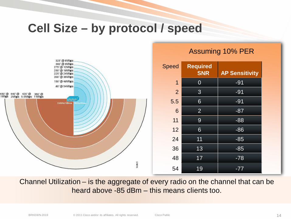
Cell Size – by protocol / speed
Assuming 10% PER
Speed Required SNR AP Sensitivity
1 0 -912 3 -91
5.5 6 -916 2 -87
11 9 -8812 6 -8624 11 -8536 13 -8548 17 -78
54 19 -77
Channel Utilization – is the aggregate of every radio on the channel that can be heard above -85 dBm – this means clients too.
© 2011 Cisco and/or its affiliates. All rights reserved. Cisco PublicBRKEWN-2019 15
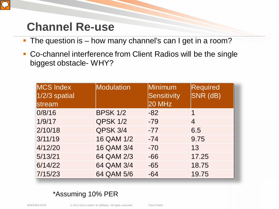
The question is – how many channel’s can I get in a room?
Co-channel interference from Client Radios will be the single biggest obstacle- WHY?
Channel Re-use
MCS Index1/2/3 spatial stream
Modulation Minimum Sensitivity20 MHz
Required SNR (dB)
0/8/16 BPSK 1/2 -82 11/9/17 QPSK 1/2 -79 42/10/18 QPSK 3/4 -77 6.53/11/19 16 QAM 1/2 -74 9.754/12/20 16 QAM 3/4 -70 135/13/21 64 QAM 2/3 -66 17.256/14/22 64 QAM 3/4 -65 18.757/15/23 64 QAM 5/6 -64 19.75
*Assuming 10% PER
© 2011 Cisco and/or its affiliates. All rights reserved. Cisco PublicBRKEWN-2019 16
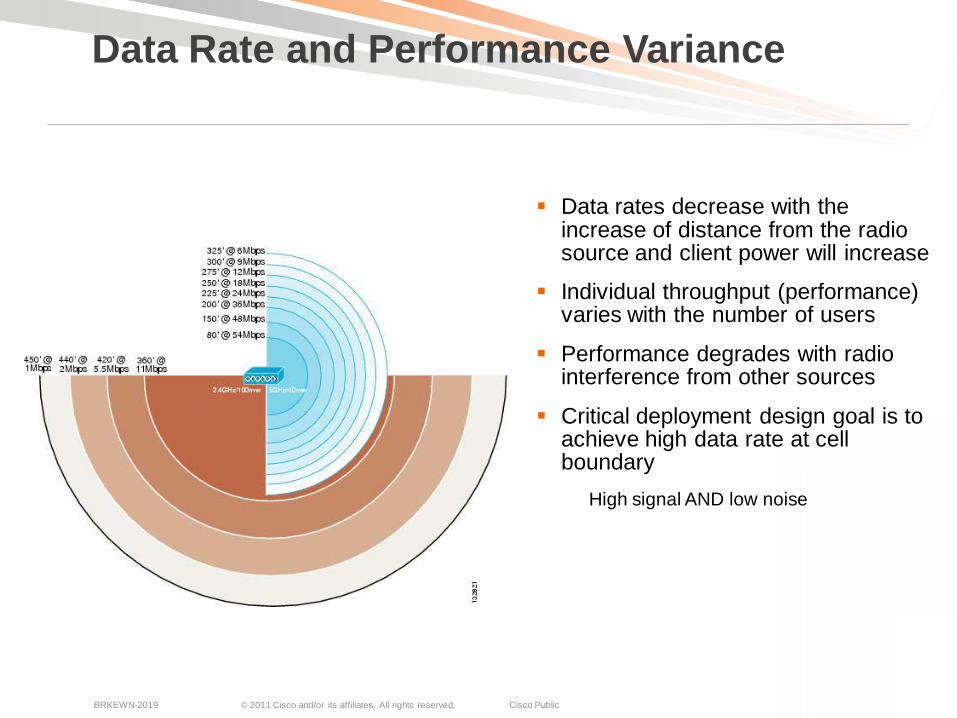
Data rates decrease with the increase of distance from the radio source and client power will increase
Individual throughput (performance) varies with the number of users
Performance degrades with radio interference from other sources
Critical deployment design goal is to achieve high data rate at cell boundary
High signal AND low noise
Data Rate and Performance Variance
© 2011 Cisco and/or its affiliates. All rights reserved. Cisco PublicBRKEWN-2019 17
802.11 is CSMA/CA – collision avoidance
CCA is Clear Channel Assessment – and is the listen before talk component of Collision Avoidance
With 802.11n radios CCA is typically linked to Preamble/Start of packet
Radios are better (mostly)
CCA - is -85 dBm for 802.11b/g/a
If you can hear it above that – you are sharing the spectrum
What is CCA?
© 2011 Cisco and/or its affiliates. All rights reserved. Cisco PublicBRKEWN-2019 18
In a High Density Client environment, the AP’s will have the best view of the room often line of site to the client (in overhead mounting)
Client devices will be embedded with the users and result in a 10-15 dB attenuation. This serves to reduce the overall interference radius of the clients.
Difficult to predict the radio dynamics affecting the client unless direct measurements can be taken when space is filled.
Very possible to focus on the AP and it’s view of the world and improve downlink performance.
The object is to make the network resilient by optimizing every aspect within our control
Cell Isolation

© 2011 Cisco and/or its affiliates. All rights reserved. Cisco PublicBRKEWN-2019 19
Range versus rate is something that we are generally working to maximize in a coverage design - However
In High Density Design, the reverse is actually true – we want to minimize the propagation of a cell
Minimizing the cell size is a function of limiting the propagation, there are 3 ways to do this–
1. Limiting supported rates
2. Managing the power of the radio’s (AP and Client)
3. Using the right antenna’s to shape both Tx and Rx cell size
Properly applied, this will maximize channel re-use in a small space
Channel Efficiency
© 2011 Cisco and/or its affiliates. All rights reserved. Cisco PublicBRKEWN-2019 20
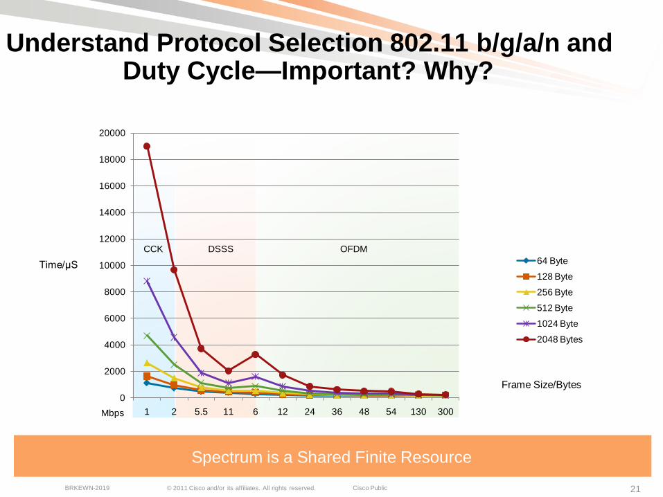
Duty Cycle is the on time of a given transmitter
It is measured as percentage of total time available, this relates directly to channel utilization, but is only part of the story – protocol overhead is the full story
802.11 can only do essentially two things to recover in a challenging RF environment
Retransmit a Frame – Turn the radio on again to send information that has already been sent once = Increased Duty Cycle
Rate shift to a slower speed that can be supported – If retries are excessive, then the link will be rate shifted to a slower speed in an attempt to gain reliability
Both of these will increase Duty Cycle and make the problem worse if it is a dense network
Duty Cycle – and Spectrum Capacity
© 2011 Cisco and/or its affiliates. All rights reserved. Cisco PublicBRKEWN-2019 21
Understand Protocol Selection 802.11 b/g/a/n and Duty Cycle—Important? Why?
Spectrum is a Shared Finite Resource
CCK DSSS OFDM
0
2000
4000
6000
8000
10000
12000
14000
16000
18000
20000
1 2 5.5 11 6 12 24 36 48 54 130 300
64 Byte
128 Byte
256 Byte
512 Byte
1024 Byte
2048 Bytes
Time/μS
Mbps
Frame Size/Bytes
© 2011 Cisco and/or its affiliates. All rights reserved. Cisco PublicBRKEWN-2019 26
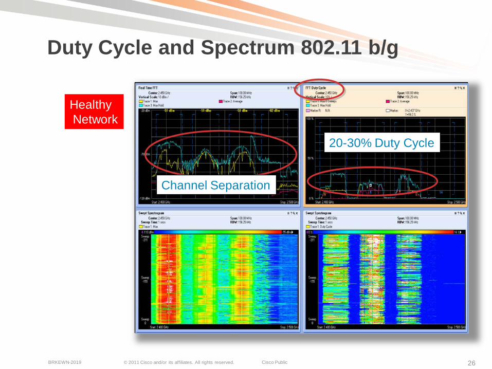
Duty Cycle and Spectrum 802.11 b/g
Channel Separation
20-30% Duty Cycle
HealthyNetwork
© 2011 Cisco and/or its affiliates. All rights reserved. Cisco PublicBRKEWN-2019 27
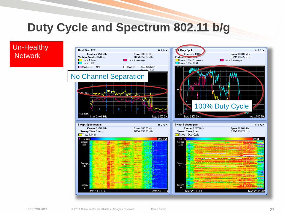
Duty Cycle and Spectrum 802.11 b/g
No Channel Separation
100% Duty Cycle
Un-HealthyNetwork
© 2011 Cisco and/or its affiliates. All rights reserved. Cisco PublicBRKEWN-2019 28
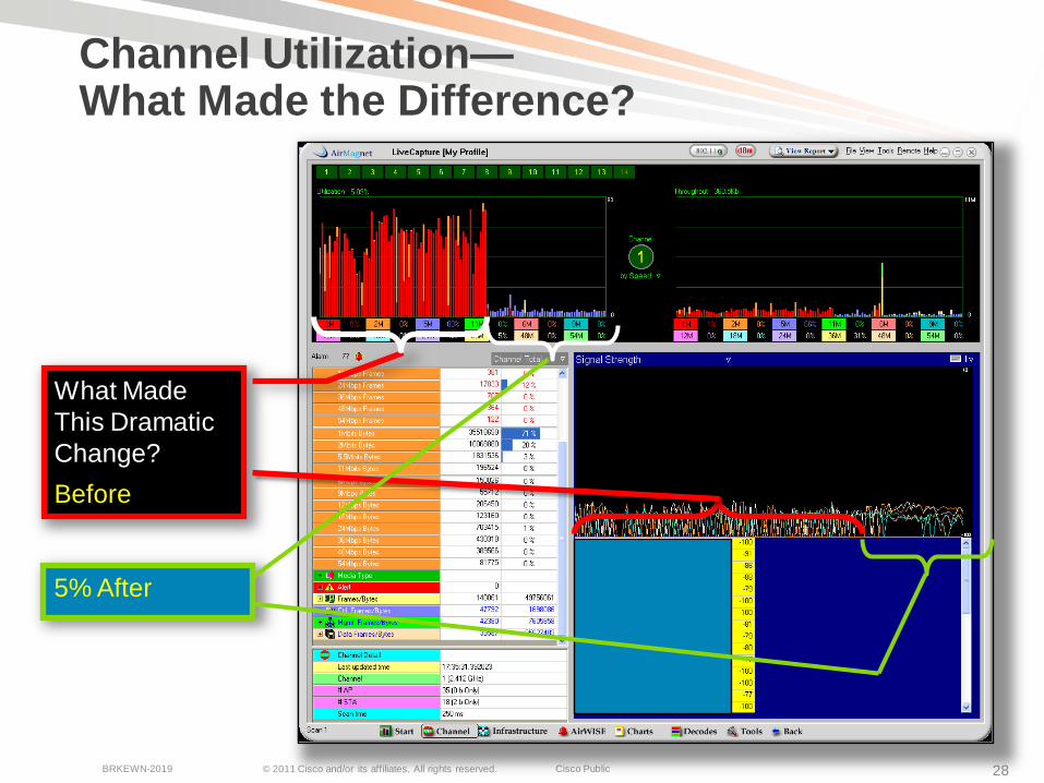
Channel Utilization—What Made the Difference?
What Made This DramaticChange? Before
5% After
© 2011 Cisco and/or its affiliates. All rights reserved. Cisco PublicBRKEWN-2019 29
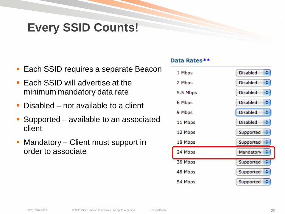
Every SSID Counts!
Each SSID requires a separate Beacon
Each SSID will advertise at the minimum mandatory data rate
Disabled – not available to a client
Supported – available to an associated client
Mandatory – Client must support in order to associate
© 2011 Cisco and/or its affiliates. All rights reserved. Cisco PublicBRKEWN-2019 30
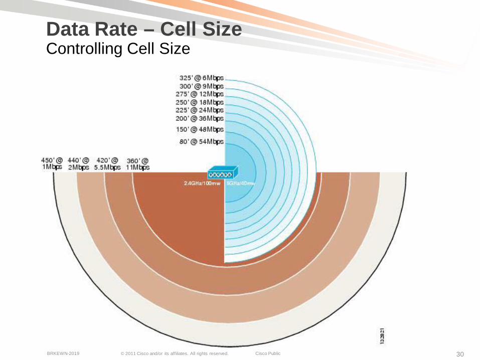
Data Rate – Cell Size Controlling Cell Size
© 2011 Cisco and/or its affiliates. All rights reserved. Cisco PublicBRKEWN-2019 31
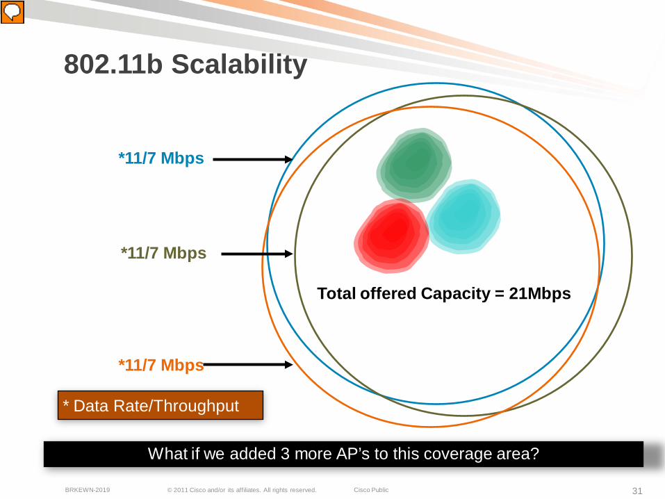
802.11b Scalability
What if we added 3 more AP’s to this coverage area?
*11/7 Mbps
*11/7 Mbps
*11/7 Mbps
Total offered Capacity = 21Mbps
* Data Rate/Throughput
© 2011 Cisco and/or its affiliates. All rights reserved. Cisco PublicBRKEWN-2019 32
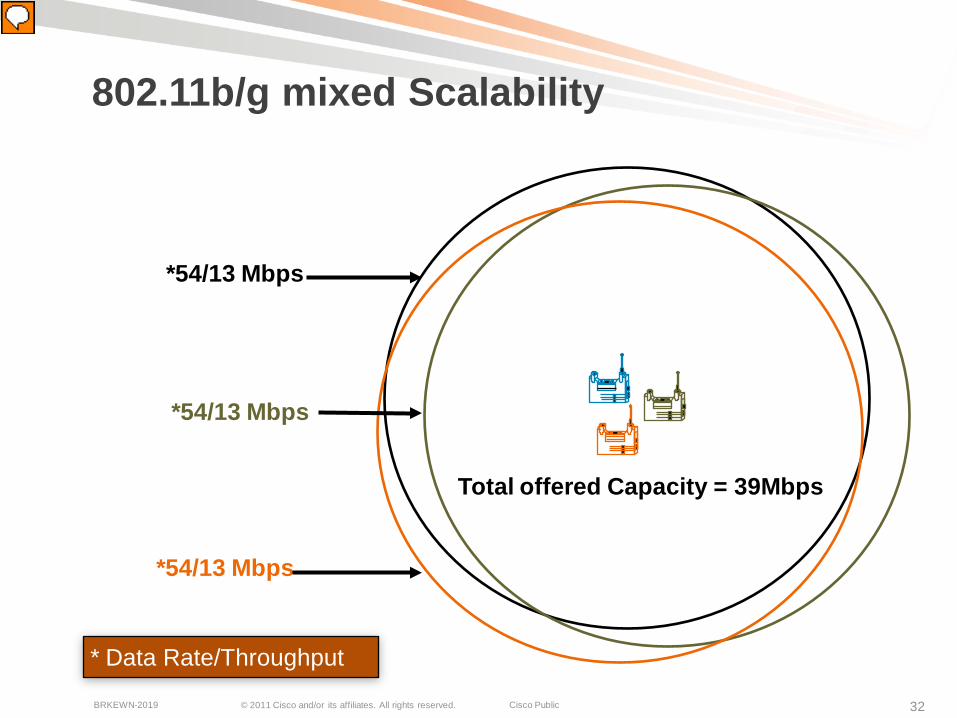
802.11b/g mixed Scalability
*54/13 Mbps
*54/13 Mbps
*54/13 Mbps
Total offered Capacity = 39Mbps
* Data Rate/Throughput

© 2011 Cisco and/or its affiliates. All rights reserved. Cisco PublicBRKEWN-2019 33
What about 11n? 9-bonded channels
802.11a Scalability – US 5 GHz has 21 Indoor Channels
*54/25 Mbps
*54/25 Mbps
*54/25 Mbps
Total offered capacity =500 Mbps!
*54/25 Mbps*54/25 Mbps
*54/25 Mbps
*54/25 Mbps
*54/25 Mbps
*54/25 Mbps
* Data Rate/Throughput
20Channels x25 Mbps
© 2011 Cisco and/or its affiliates. All rights reserved. Cisco PublicBRKEWN-2019 34
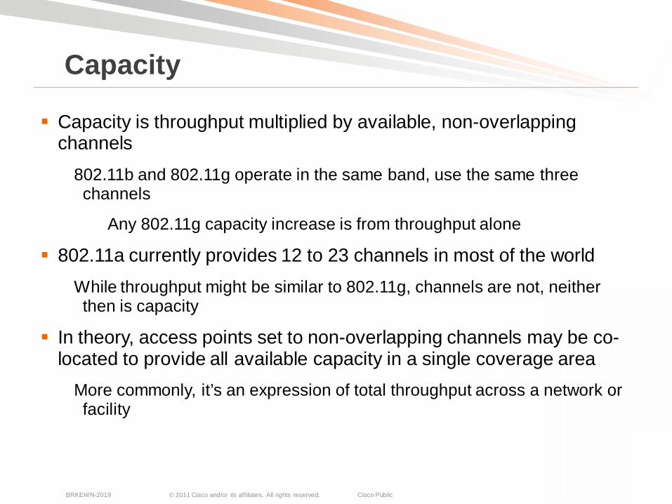
Capacity is throughput multiplied by available, non-overlapping channels
802.11b and 802.11g operate in the same band, use the same three channels
Any 802.11g capacity increase is from throughput alone
802.11a currently provides 12 to 23 channels in most of the worldWhile throughput might be similar to 802.11g, channels are not, neither then is capacity
In theory, access points set to non-overlapping channels may be co-located to provide all available capacity in a single coverage area
More commonly, it’s an expression of total throughput across a network or facility
Capacity
© 2011 Cisco and/or its affiliates. All rights reserved. Cisco PublicBRKEWN-2019 35
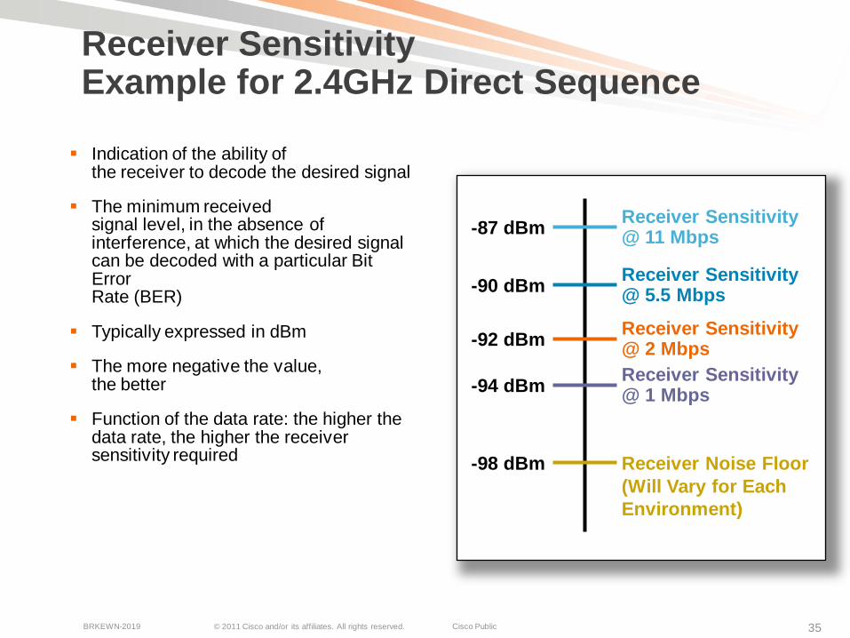
Receiver SensitivityExample for 2.4GHz Direct Sequence
Indication of the ability of the receiver to decode the desired signal
The minimum receivedsignal level, in the absence of interference, at which the desired signal can be decoded with a particular Bit ErrorRate (BER)
Typically expressed in dBm
The more negative the value,the better
Function of the data rate: the higher the data rate, the higher the receiver sensitivity required Receiver Noise Floor
(Will Vary for Each Environment)
-92 dBm Receiver Sensitivity @ 2 MbpsReceiver Sensitivity @ 1 Mbps-94 dBm
-98 dBm
-90 dBm Receiver Sensitivity @ 5.5 Mbps
-87 dBm Receiver Sensitivity @ 11 Mbps
© 2011 Cisco and/or its affiliates. All rights reserved. Cisco PublicBRKEWN-2019 36
52.4
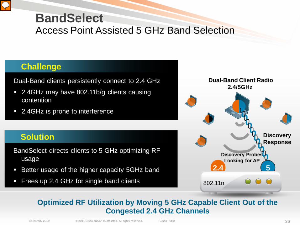
Optimized RF Utilization by Moving 5 GHz Capable Client Out of the Congested 2.4 GHz Channels
802.11n
BandSelectAccess Point Assisted 5 GHz Band Selection
Dual-Band Client Radio2.4/5GHz
Discovery ProbesLooking for AP
Discovery Response
SolutionBandSelect directs clients to 5 GHz optimizing RF
usage
Better usage of the higher capacity 5GHz band
Frees up 2.4 GHz for single band clients
ChallengeDual-Band clients persistently connect to 2.4 GHz
2.4GHz may have 802.11b/g clients causing contention
2.4GHz is prone to interference
© 2011 Cisco and/or its affiliates. All rights reserved. Cisco PublicBRKEWN-2019 37
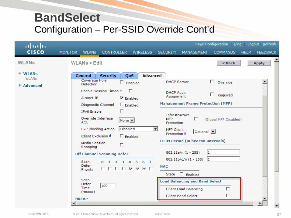
BandSelectConfiguration – Per-SSID Override Cont’d
© 2011 Cisco and/or its affiliates. All rights reserved. Cisco PublicBRKEWN-2019 38
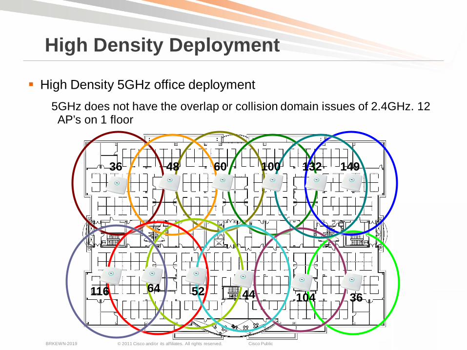
36 48 60 100 132 149
116 64 52 44 104 36
High Density 5GHz office deployment5GHz does not have the overlap or collision domain issues of 2.4GHz. 12 AP’s on 1 floor
High Density Deployment
© 2011 Cisco and/or its affiliates. All rights reserved. Cisco PublicBRKEWN-2019 39
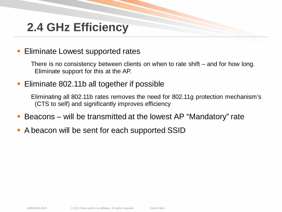
Eliminate Lowest supported ratesThere is no consistency between clients on when to rate shift – and for how long.
Eliminate support for this at the AP.
Eliminate 802.11b all together if possibleEliminating all 802.11b rates removes the need for 802.11g protection mechanism’s
(CTS to self) and significantly improves efficiency
Beacons – will be transmitted at the lowest AP “Mandatory” rate
A beacon will be sent for each supported SSID
2.4 GHz Efficiency
© 2011 Cisco and/or its affiliates. All rights reserved. Cisco PublicBRKEWN-2019 40
Select Supported Protocols
Design Steps
Determine ApplicationRequirements
Determine AP typeAnd Placement
Tune the Configuration

© 2011 Cisco and/or its affiliates. All rights reserved. Cisco PublicBRKEWN-2019 41
The type of AP you select will have a large impact on the amount of data that you successfully deliver
Any AP that you consider should at a minimum have diversity antennae's
802.11n AP’s in general provide improved performance for legacy clients
802.11n Clients get a huge benefit – and relieve a lot of stress on bandwidth for legacy clients (140 mbps connections for 802.11n in 20 MHz)
In all cases – Stock Omni antenna’s are the recommended approach
Selection of AP’s
© 2011 Cisco and/or its affiliates. All rights reserved. Cisco PublicBRKEWN-2019 42
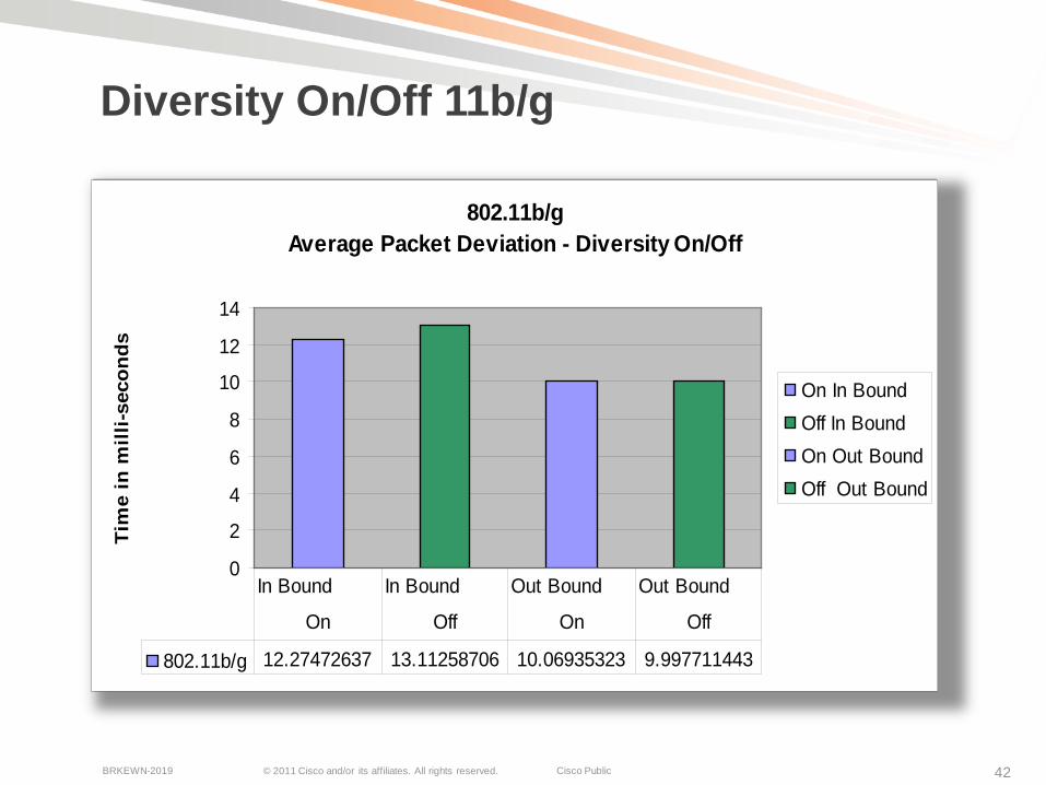
Diversity On/Off 11b/g
802.11b/gAverage Packet Deviation - Diversity On/Off
0
2
4
6
8
10
12
14
Tim
e in
mill
i-sec
onds
On In BoundOff In BoundOn Out BoundOff Out Bound
802.11b/g 12.27472637 13.11258706 10.06935323 9.997711443
In Bound In Bound Out Bound Out Bound
On Off On Off
© 2011 Cisco and/or its affiliates. All rights reserved. Cisco PublicBRKEWN-2019 43
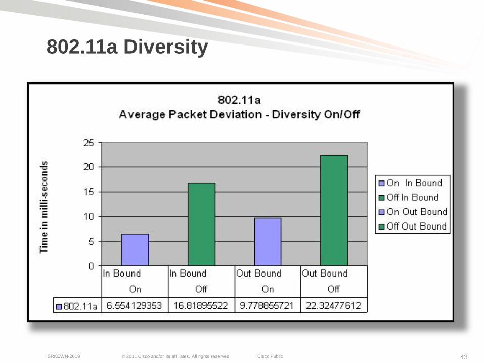
802.11a Diversity

© 2011 Cisco and/or its affiliates. All rights reserved. Cisco PublicBRKEWN-2019 44
Gain
A theoretical isotropic antenna has a perfect 360º vertical and horizontal beamwidth
This is a reference for all antennae Gain is equal in all directions The reception of good signals
and interference is the same in all directions
High Gain Omni-directional Antennae: More coverage area on the
horizontal elevation Energy level directly above
or below the antenna will become lower
Antenna Theory and Antenna Gain
There is no increase in transmitted energy with the higher gain
© 2011 Cisco and/or its affiliates. All rights reserved. Cisco PublicBRKEWN-2019 45
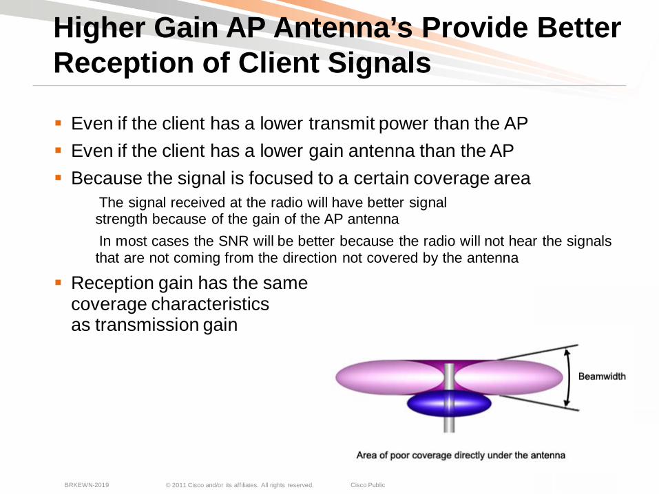
Even if the client has a lower transmit power than the AP Even if the client has a lower gain antenna than the AP Because the signal is focused to a certain coverage area
The signal received at the radio will have better signal strength because of the gain of the AP antennaIn most cases the SNR will be better because the radio will not hear the signals that are not coming from the direction not covered by the antenna
Reception gain has the same coverage characteristics as transmission gain
Higher Gain AP Antenna’s Provide Better Reception of Client Signals
© 2011 Cisco and/or its affiliates. All rights reserved. Cisco PublicBRKEWN-2019 46
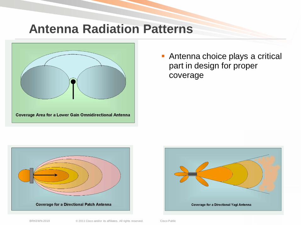
Antenna choice plays a critical part in design for proper coverage
Antenna Radiation Patterns

© 2011 Cisco and/or its affiliates. All rights reserved. Cisco PublicBRKEWN-2019 47
Product ID Description Gain F/B A/E
AIR-ANT2452V-R=2.4 GHz 5.2 dBi Diversity pillar mount ant,RP-TNC Connectors
5.2 dBi N/A Omni
AIR-ANT2451NV-R=2.4 GHz 3 dBi/5 GHz 4 dBi 802.11n dual band omni antenna
3 dbi/4 dBi N/A Omni
AIR-ANT2460NP-R= 2.4 GHz 6 dBi 802.11n directional antenna 6 dBi 10 dB 80/75
AIR-ANT5160NP-R= 5 GHz 6 dBi 802.11n directional antenna 6 dBi >15 dB 65/65
AIR-ANT2422SDW-R= 2.4 GHz 2.2 dBi Short white dipole antenna, Qty 1 2.2 dBi N/A Omni
AIR-ANT5135SDW-R= 5 GHz 3.5 dBi Short white dipole antenna, Qty. 1 3.5 dBi N/A Omni
AIR-ANT2440NV-R= 2.4 GHz 4 dBi 802.11n Omni wall mount antenna 4 dBi N/A Omni
AIR-ANT5140NV-R= 5 GHz 4 dBi 802.11n Omni wall mount antenna 4 dBi N/A Omni
Antenna Options

© 2011 Cisco and/or its affiliates. All rights reserved. Cisco PublicBRKEWN-2019 48
Ruggedized 11n Enterprise AP’s
12603500e1250
© 2011 Cisco and/or its affiliates. All rights reserved. Cisco PublicBRKEWN-2019 49
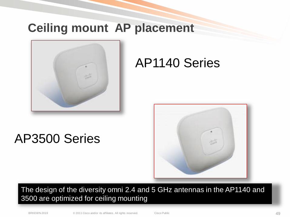
Ceiling mount AP placement
AP3500 Series
AP1140 Series
The design of the diversity omni 2.4 and 5 GHz antennas in the AP1140 and 3500 are optimized for ceiling mounting
© 2011 Cisco and/or its affiliates. All rights reserved. Cisco PublicBRKEWN-2019 50
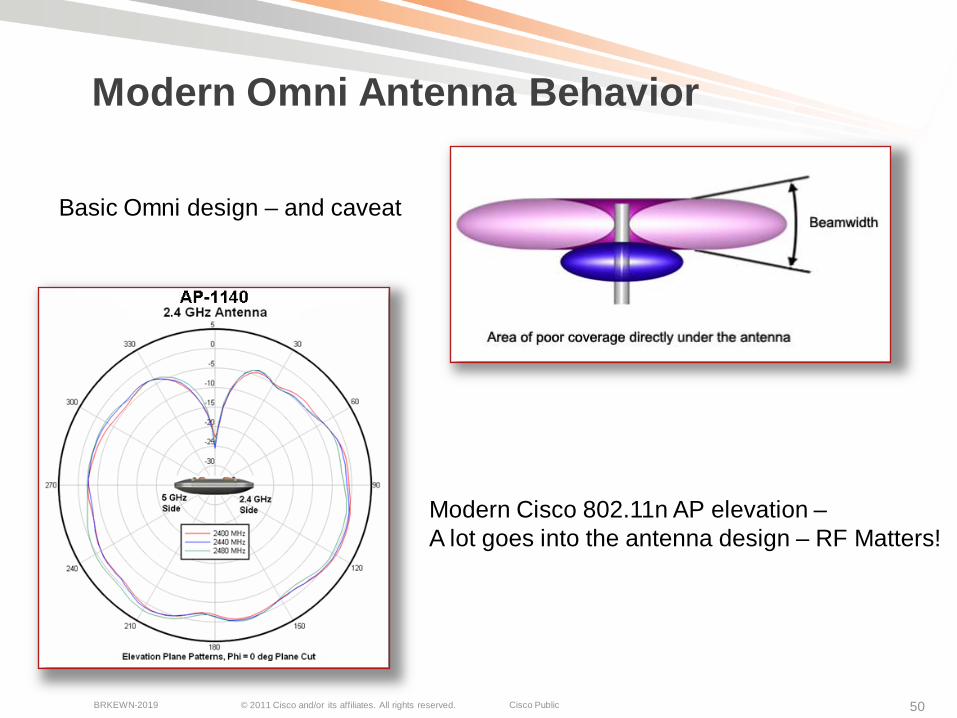
Modern Omni Antenna Behavior
Basic Omni design – and caveat
Modern Cisco 802.11n AP elevation –A lot goes into the antenna design – RF Matters!
© 2011 Cisco and/or its affiliates. All rights reserved. Cisco PublicBRKEWN-2019 51
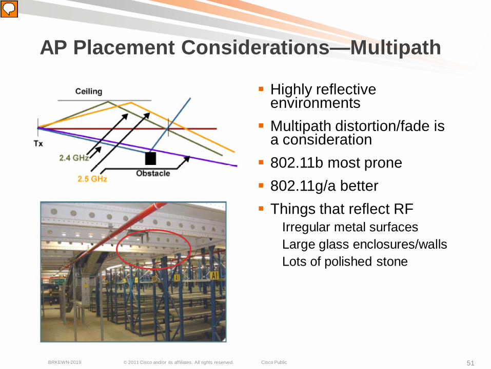
AP Placement Considerations—Multipath
Highly reflective environments Multipath distortion/fade is
a consideration 802.11b most prone 802.11g/a better Things that reflect RF
Irregular metal surfacesLarge glass enclosures/wallsLots of polished stone
© 2011 Cisco and/or its affiliates. All rights reserved. Cisco PublicBRKEWN-2019 52
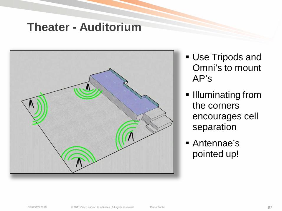
Theater - Auditorium
Use Tripods and Omni’s to mount AP’s
Illuminating from the corners encourages cell separation
Antennae’s pointed up!
© 2011 Cisco and/or its affiliates. All rights reserved. Cisco PublicBRKEWN-2019 53
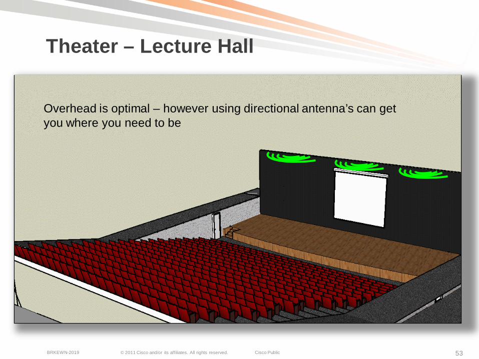
Theater – Lecture Hall
Overhead is optimal – however using directional antenna’s can get you where you need to be

© 2011 Cisco and/or its affiliates. All rights reserved. Cisco PublicBRKEWN-2019 54
Small Sporting Event
Illuminating from the sides focuses energy near users
The center is not likely to need much connectivity
Omni Patch, or wall mounted
© 2011 Cisco and/or its affiliates. All rights reserved. Cisco PublicBRKEWN-2019 55
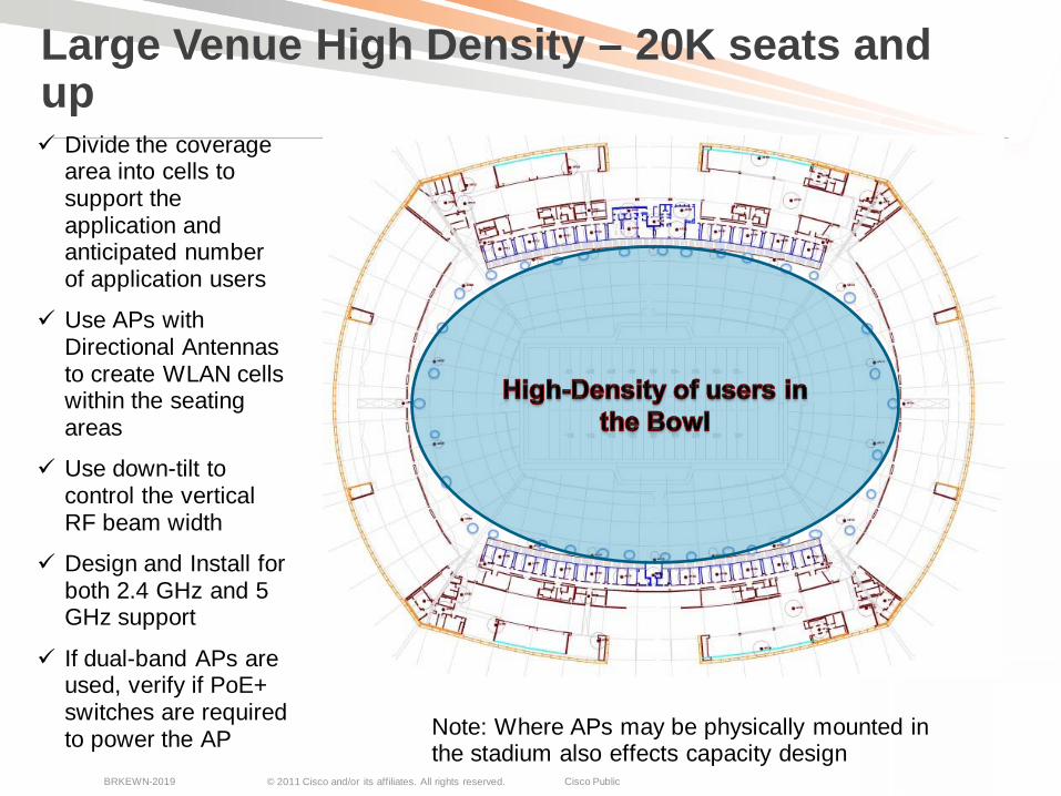
Large Venue High Density – 20K seats and up Divide the coverage
area into cells to support the application and anticipated number of application users
Use APs with Directional Antennas to create WLAN cells within the seating areas
Use down-tilt to control the vertical RF beam width
Design and Install for both 2.4 GHz and 5 GHz support
If dual-band APs are used, verify if PoE+ switches are required to power the AP Note: Where APs may be physically mounted in
the stadium also effects capacity design
© 2011 Cisco and/or its affiliates. All rights reserved. Cisco PublicBRKEWN-2019 56
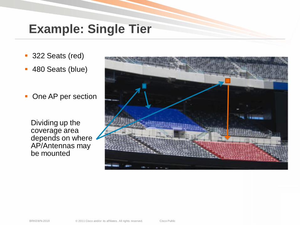
322 Seats (red)
480 Seats (blue)
One AP per section
Example: Single Tier
Dividing up the coverage area depends on where AP/Antennas may be mounted

© 2011 Cisco and/or its affiliates. All rights reserved. Cisco PublicBRKEWN-2019 57
1020 Seats
96’ Deep
47’ Wide
Example: Two-Tiered RF Design
Seating sections in the lower bowl are served by different AP
© 2011 Cisco and/or its affiliates. All rights reserved. Cisco PublicBRKEWN-2019 58
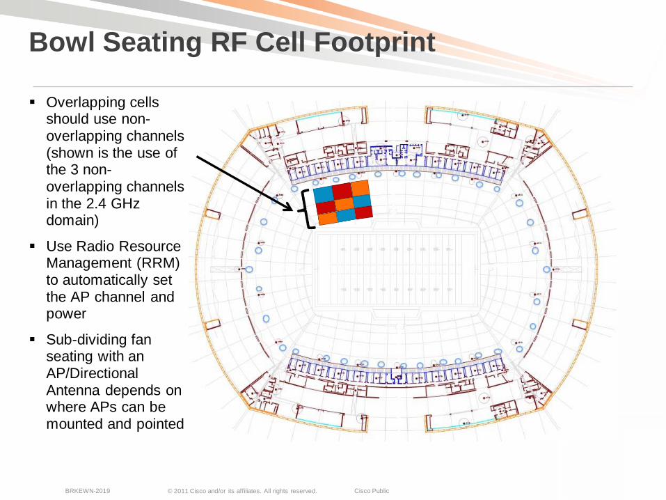
Bowl Seating RF Cell Footprint
Overlapping cellsshould use non-overlapping channels (shown is the use of the 3 non-overlapping channels in the 2.4 GHz domain)
Use Radio Resource Management (RRM) to automatically set the AP channel and power
Sub-dividing fanseating with an AP/Directional Antenna depends on where APs can be mounted and pointed
© 2011 Cisco and/or its affiliates. All rights reserved. Cisco PublicBRKEWN-2019 59
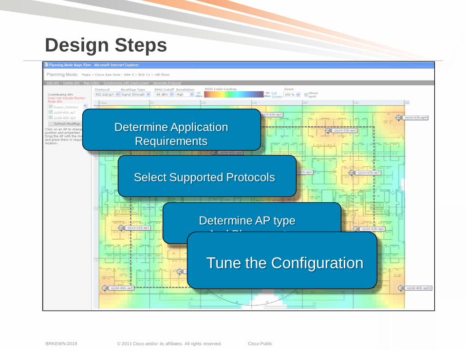
Design Steps
Determine ApplicationRequirements
Select Supported Protocols
Determine AP typeAnd Placement
Tune the ConfigurationTune the Configuration
© 2011 Cisco and/or its affiliates. All rights reserved. Cisco PublicBRKEWN-2019 60
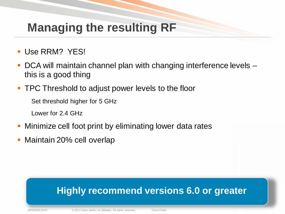
Use RRM? YES!
DCA will maintain channel plan with changing interference levels –this is a good thing
TPC Threshold to adjust power levels to the floorSet threshold higher for 5 GHz
Lower for 2.4 GHz
Minimize cell foot print by eliminating lower data rates
Maintain 20% cell overlap
Managing the resulting RF
Highly recommend versions 6.0 or greater
© 2011 Cisco and/or its affiliates. All rights reserved. Cisco PublicBRKEWN-2019 61
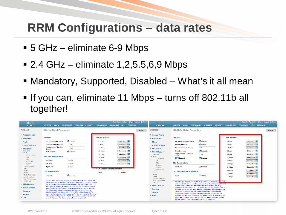
RRM Configurations – data rates 5 GHz – eliminate 6-9 Mbps
2.4 GHz – eliminate 1,2,5.5,6,9 Mbps
Mandatory, Supported, Disabled – What’s it all mean
If you can, eliminate 11 Mbps – turns off 802.11b all together!
© 2011 Cisco and/or its affiliates. All rights reserved. Cisco PublicBRKEWN-2019 62
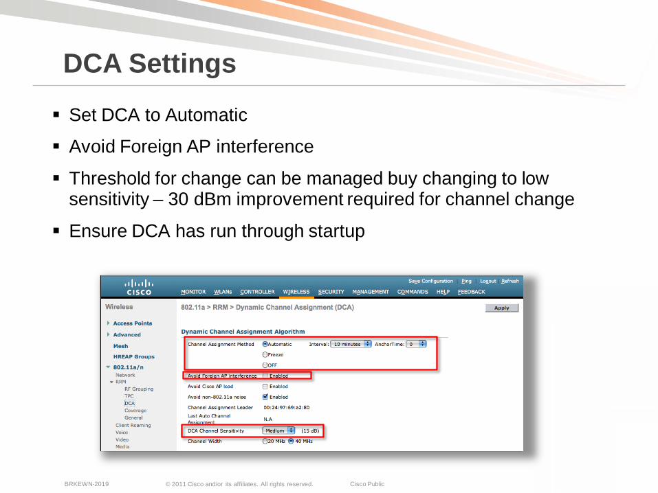
DCA Settings
Set DCA to Automatic
Avoid Foreign AP interference
Threshold for change can be managed buy changing to low sensitivity – 30 dBm improvement required for channel change
Ensure DCA has run through startup
© 2011 Cisco and/or its affiliates. All rights reserved. Cisco PublicBRKEWN-2019 63
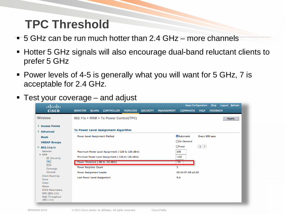
TPC Threshold 5 GHz can be run much hotter than 2.4 GHz – more channels
Hotter 5 GHz signals will also encourage dual-band reluctant clients to prefer 5 GHz
Power levels of 4-5 is generally what you will want for 5 GHz, 7 is acceptable for 2.4 GHz.
Test your coverage – and adjust
© 2011 Cisco and/or its affiliates. All rights reserved. Cisco PublicBRKEWN-2019 64
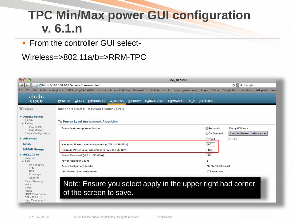
From the controller GUI select-
Wireless=>802.11a/b=>RRM-TPC
TPC Min/Max power GUI configurationv. 6.1.n
Note: Ensure you select apply in the upper right had cornerof the screen to save.
© 2011 Cisco and/or its affiliates. All rights reserved. Cisco PublicBRKEWN-2019 65
802.11a/g
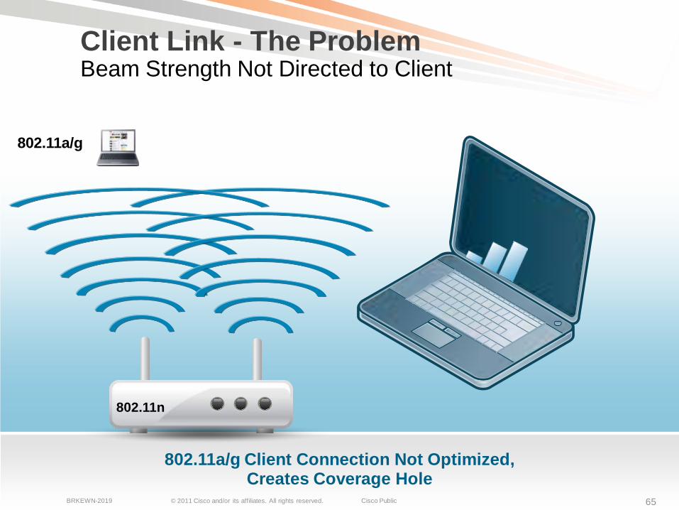
802.11a/g Client Connection Not Optimized, Creates Coverage Hole
802.11n
Client Link - The ProblemBeam Strength Not Directed to Client
© 2011 Cisco and/or its affiliates. All rights reserved. Cisco PublicBRKEWN-2019 66
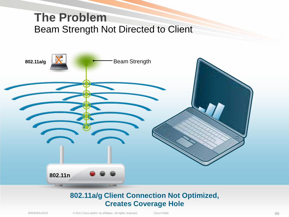
802.11a/g Client Connection Not Optimized, Creates Coverage Hole
The ProblemBeam Strength Not Directed to Client
802.11n
802.11a/g Beam StrengthX
© 2011 Cisco and/or its affiliates. All rights reserved. Cisco PublicBRKEWN-2019 67
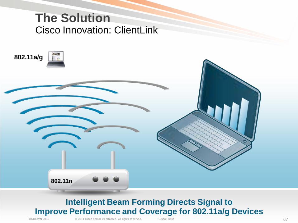
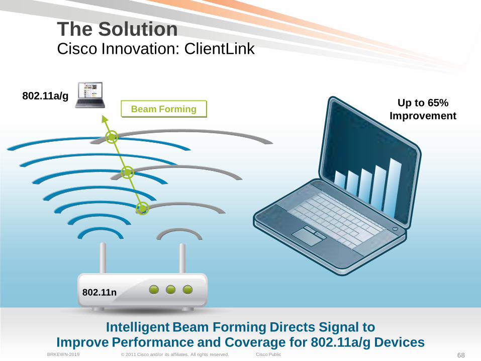
Intelligent Beam Forming Directs Signal to Improve Performance and Coverage for 802.11a/g Devices
802.11a/g
802.11n
The SolutionCisco Innovation: ClientLink
© 2011 Cisco and/or its affiliates. All rights reserved. Cisco PublicBRKEWN-2019 68
Intelligent Beam Forming Directs Signal to Improve Performance and Coverage for 802.11a/g Devices
Beam Forming802.11a/g
802.11n
Up to 65% Improvement
The SolutionCisco Innovation: ClientLink
© 2011 Cisco and/or its affiliates. All rights reserved. Cisco PublicBRKEWN-2019 69
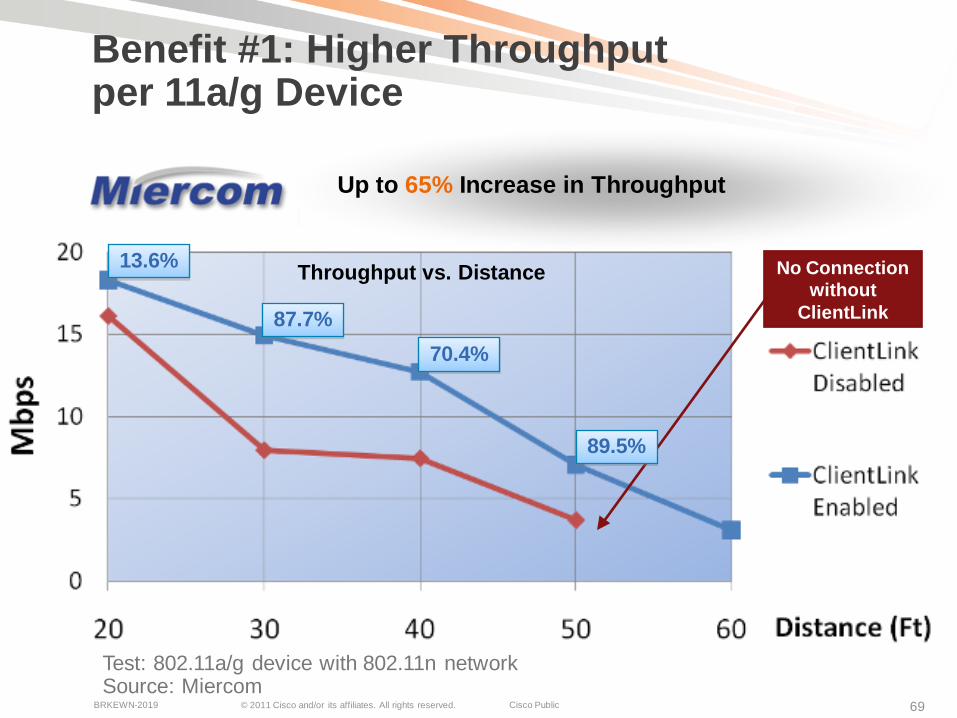
Benefit #1: Higher Throughput per 11a/g Device
No Connection without
ClientLink
Throughput vs. Distance
Test: 802.11a/g device with 802.11n networkSource: Miercom
Up to 65% Increase in Throughput
13.6%
87.7%70.4%
89.5%
© 2011 Cisco and/or its affiliates. All rights reserved. Cisco PublicBRKEWN-2019 70
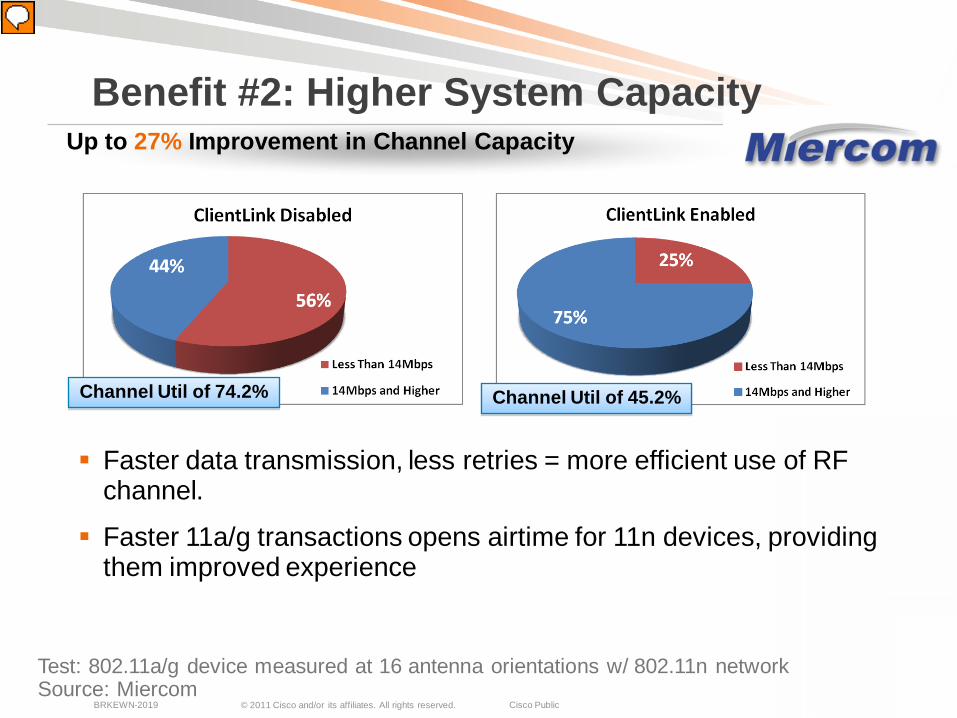
Test: 802.11a/g device measured at 16 antenna orientations w/ 802.11n networkSource: Miercom
Faster data transmission, less retries = more efficient use of RF channel.
Faster 11a/g transactions opens airtime for 11n devices, providing them improved experience
Benefit #2: Higher System CapacityUp to 27% Improvement in Channel Capacity
Channel Util of 74.2% Channel Util of 45.2%
© 2011 Cisco and/or its affiliates. All rights reserved. Cisco PublicBRKEWN-2019 71
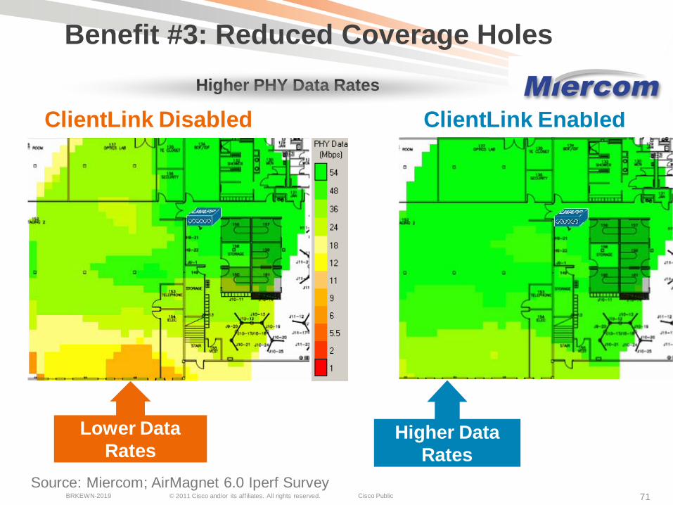
Benefit #3: Reduced Coverage Holes
ClientLink Disabled ClientLink Enabled
Lower Data Rates
Higher Data Rates
Source: Miercom; AirMagnet 6.0 Iperf Survey
Higher PHY Data Rates
© 2011 Cisco and/or its affiliates. All rights reserved. Cisco PublicBRKEWN-2019 72
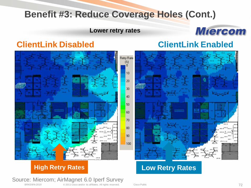
Benefit #3: Reduce Coverage Holes (Cont.)
ClientLink Disabled ClientLink Enabled
High Retry Rates Low Retry RatesSource: Miercom; AirMagnet 6.0 Iperf Survey
Lower retry rates
© 2011 Cisco and/or its affiliates. All rights reserved. Cisco PublicBRKEWN-2019 73
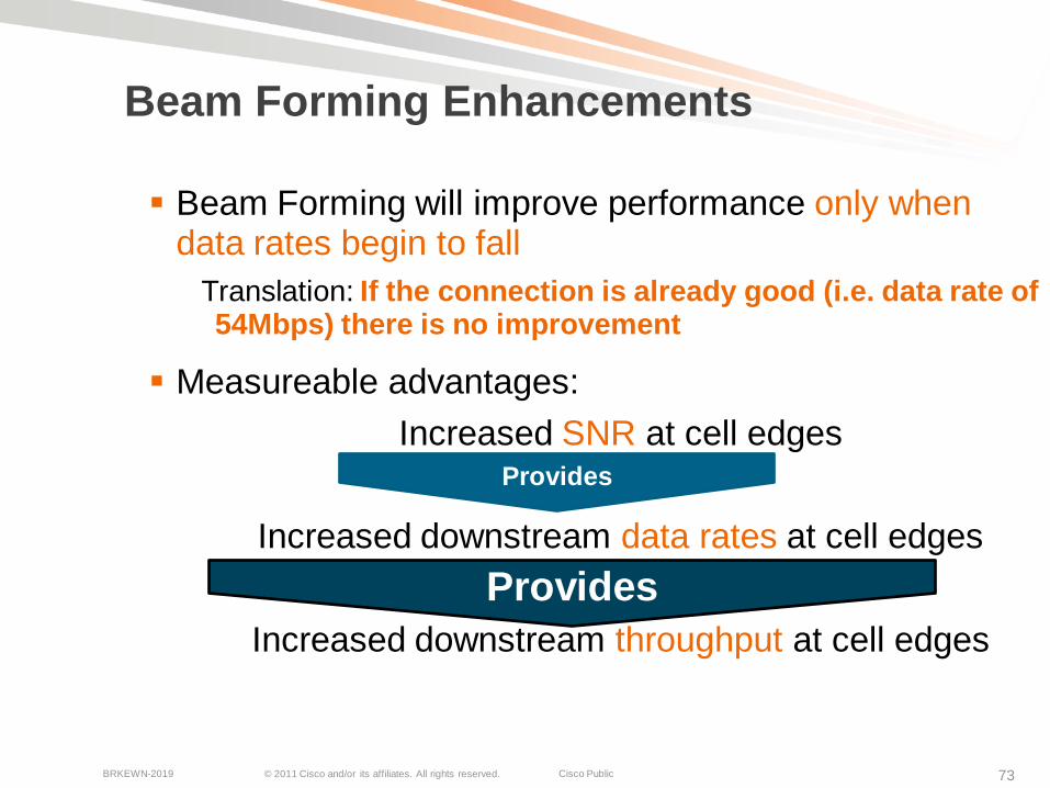
Beam Forming Enhancements
Beam Forming will improve performance only when data rates begin to fall
Translation: If the connection is already good (i.e. data rate of 54Mbps) there is no improvement
Measureable advantages:Increased SNR at cell edges
Increased downstream data rates at cell edges
Increased downstream throughput at cell edges
Provides
Provides
© 2011 Cisco and/or its affiliates. All rights reserved. Cisco PublicBRKEWN-2019 74
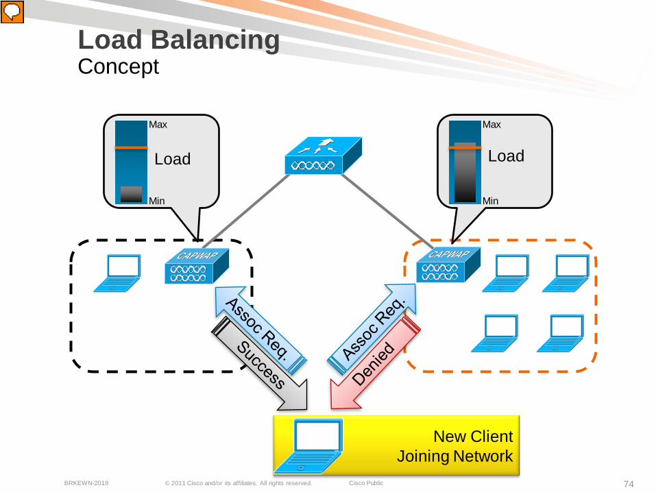
New Client Joining Network
Load BalancingConcept
Load
Min
Max
Load
Min
Max
© 2011 Cisco and/or its affiliates. All rights reserved. Cisco PublicBRKEWN-2019 75
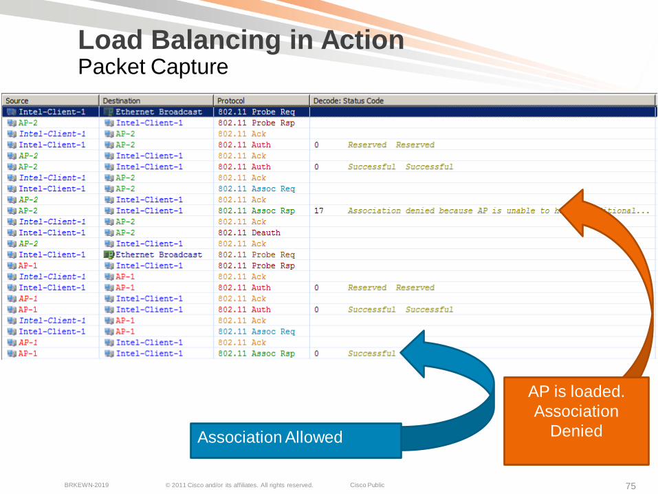
Load Balancing in ActionPacket Capture
AP is loaded.Association
DeniedAssociation Allowed
© 2011 Cisco and/or its affiliates. All rights reserved. Cisco PublicBRKEWN-2019 76
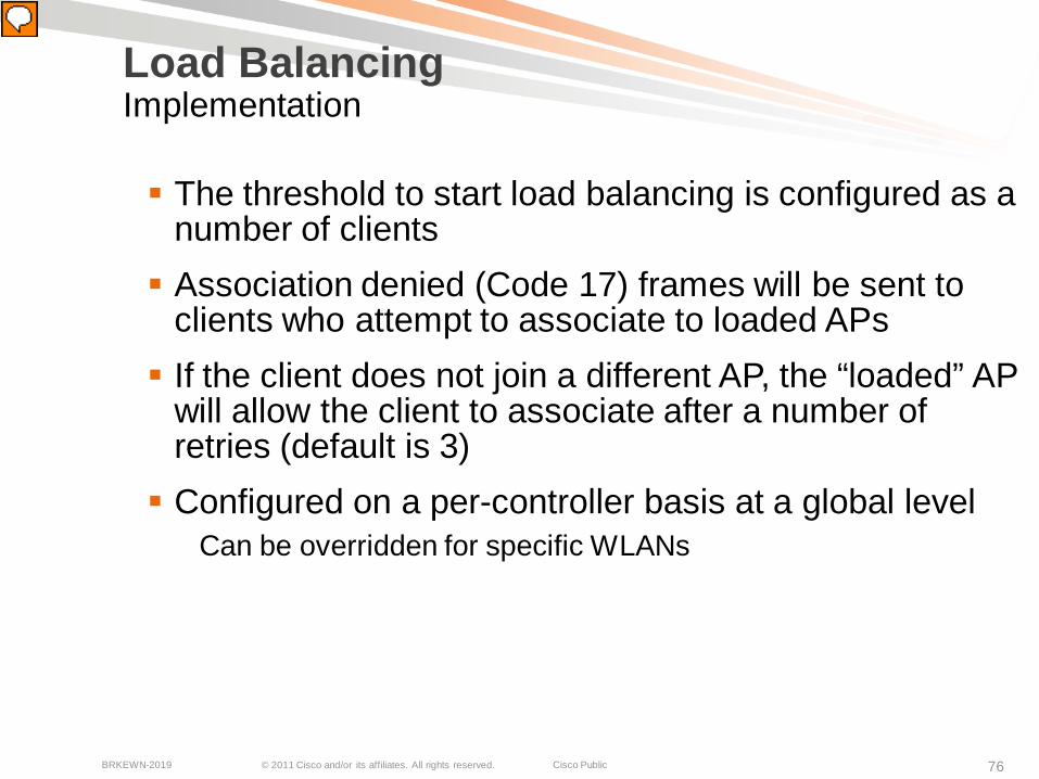
Load BalancingImplementation
The threshold to start load balancing is configured as a number of clients Association denied (Code 17) frames will be sent to
clients who attempt to associate to loaded APs If the client does not join a different AP, the “loaded” AP
will allow the client to associate after a number of retries (default is 3) Configured on a per-controller basis at a global level
Can be overridden for specific WLANs
© 2011 Cisco and/or its affiliates. All rights reserved. Cisco PublicBRKEWN-2019 77
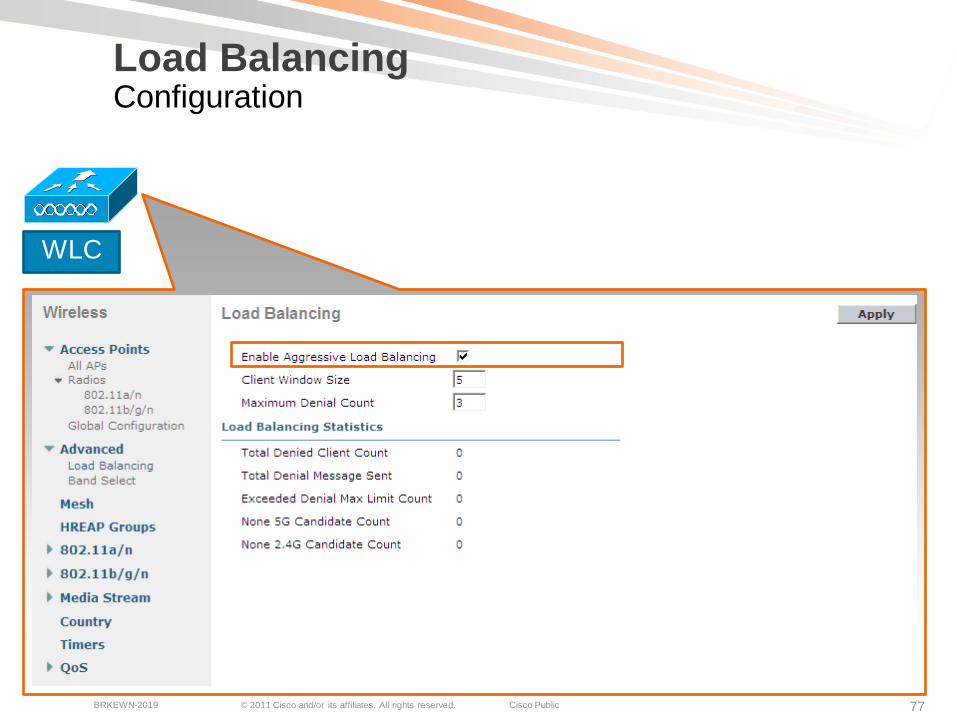
Load Balancing Configuration
(Cisco Controller) >config load-balancing aggressive enable
WARNING: Allowing load balance may impact time sensitive application like VOICEContinue? (y/N)y
(Cisco Controller) >show load-balancing
Aggressive Load Balancing........................ EnabledAggressive Load Balancing Window................. 5 clientsAggressive Load Balancing Denial Count........... 3
StatisticsTotal Denied Count............................... 0 clientsTotal Denial Sent................................ 0 messagesExceeded Denial Max Limit Count.................. 0 timesNone 5G Candidate Count.......................... 0 timesNone 2.4G Candidate Count........................ 0 times
WLC
© 2011 Cisco and/or its affiliates. All rights reserved. Cisco PublicBRKEWN-2019 78
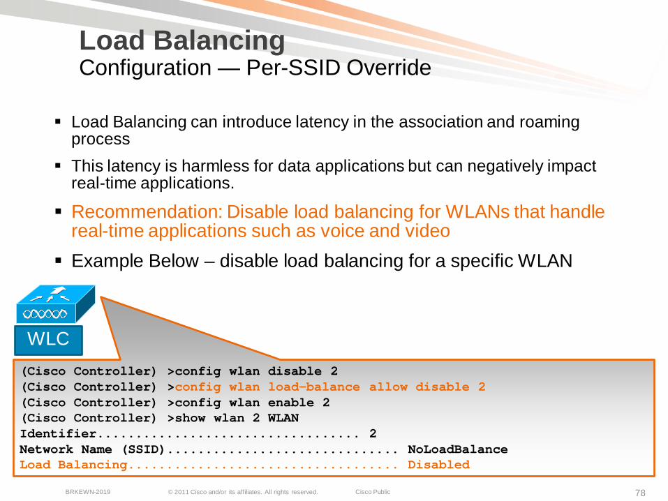
Load BalancingConfiguration — Per-SSID Override
WLC(Cisco Controller) >config wlan disable 2 (Cisco Controller) >config wlan load-balance allow disable 2(Cisco Controller) >config wlan enable 2(Cisco Controller) >show wlan 2 WLAN Identifier.................................. 2 Network Name (SSID).............................. NoLoadBalanceLoad Balancing................................... Disabled
Load Balancing can introduce latency in the association and roaming process
This latency is harmless for data applications but can negatively impact real-time applications.
Recommendation: Disable load balancing for WLANs that handle real-time applications such as voice and video
Example Below – disable load balancing for a specific WLAN
© 2011 Cisco and/or its affiliates. All rights reserved. Cisco PublicBRKEWN-2019 79
Load BalancingCaveats
Load balancing only occurs amongst APs on the same controller Load balancing requires that the client respect the
“Code 17” association response and act accordingly Load Balancing only occurs at initial association, not on
re-association. Some older clients simply ignore the “Code 17”
response and try and associate again. Known clients that load balance correctly:
Intel 4965AGN (with 12.1 or later drivers)Cisco CB-21AG (with 4.2 or later drivers)
© 2011 Cisco and/or its affiliates. All rights reserved. Cisco PublicBRKEWN-2019 80
More Information
Cisco 802.11n Design and Deployment Guidelineshttp://www.cisco.com/en/US/solutions/collateral/ns340/ns394/ns348/ns767/white
_paper_80211n_design_and_deployment_guidelines.html
ClientLink Whitepaper:http://www.cisco.com/en/US/prod/collateral/wireless/ps5678/ps10092/white_paper_c11-516389.html
ClientLink Miercom Report:http://www.cisco.com/en/US/solutions/collateral/ns340/ns394/ns348/ns767/Miercom_Test_Report_Cisco_ClientLink.pdf
© 2011 Cisco and/or its affiliates. All rights reserved. Cisco PublicBRKEWN-2019 81
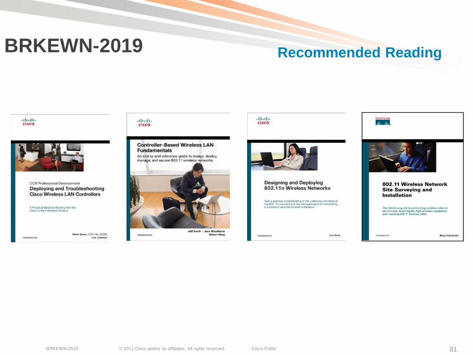
BRKEWN-2019 Recommended Reading
© 2011 Cisco and/or its affiliates. All rights reserved. Cisco PublicBRKEWN-2019 82
Housekeeping
We value your feedback- don't forget to complete your online session evaluations after each session & complete the Overall Conference Evaluation which will be available online from Thursday
Visit the World of Solutions
Please remember this is a 'non-smoking' venue!
Please switch off your mobile phones
Please make use of the recycling bins provided
Please remember to wear your badge at all times

© 2011 Cisco and/or its affiliates. All rights reserved. Cisco PublicBRKEWN-2019 90


![CSMA/CCA: A Modified CSMA/CA Protocol Mitigating the ...cheung/Courses/558/Syllabus/Papers/CSMA … · The medium access control (MAC) ... (MACA) protocol [3], ... MACAW [4]. The](https://static.documents.pub/doc/80x56/5b5b7a167f8b9a302a8e0f8a/csmacca-a-modified-csmaca-protocol-mitigating-the-cheungcourses558syllabuspaperscsma.jpg)


![Carrier-Sense Multiple Access with Transmission Acquisition (CSMA…dl.ifip.org/db/conf/networking/networking2018/5B2... · 2019-02-19 · CSMA/CD [7] implements a CSMA/CA with collision](https://static.documents.pub/doc/80x56/5e66c1cc9513ed7a406c9a73/carrier-sense-multiple-access-with-transmission-acquisition-2019-02-19-csmacd.jpg)


![Throughput optimization in DSRC for collision avoidance€¦ · CSMA/CA, where transmission by communication nodes is done after sensing an idle channel [2]. Collision avoidance attempts](https://static.documents.pub/doc/80x56/5f7b7c29fd3d4056f724da89/throughput-optimization-in-dsrc-for-collision-avoidance-csmaca-where-transmission.jpg)

![Performance Analysis of IEEE 802.15.6-Based Coexisting ... · Carrier Sense Multiple Access with Collision Avoidance (CSMA/CA) protocol [15] is employed rather than the scheduled](https://static.documents.pub/doc/80x56/5f11a882774cd617e21df580/performance-analysis-of-ieee-802156-based-coexisting-carrier-sense-multiple.jpg)