Page 1
8/11/2019 Manganese Oxide-based Materials as Electrochemical_Wei
http://slidepdf.com/reader/full/manganese-oxide-based-materials-as-electrochemicalwei 1/25
This journal is c The Royal Society of Chemistry 2011 Chem. Soc. Rev., 2011, 40, 1697–1721 1697
Cite this: Chem. Soc. Rev ., 2011, 40, 1697–1721
Manganese oxide-based materials as electrochemical
supercapacitor electrodes
Weifeng Wei,ab Xinwei Cui,a Weixing Chena and Douglas G. Ivey*a
Received 28th September 2010
DOI: 10.1039/c0cs00127a
Electrochemical supercapacitors (ECs), characteristic of high power and reasonably high
energy densities, have become a versatile solution to various emerging energy applications.
This critical review describes some materials science aspects on manganese oxide-based materials
for these applications, primarily including the strategic design and fabrication of these electrode
materials. Nanostructurization, chemical modification and incorporation with high surface
area, conductive nanoarchitectures are the three major strategies in the development of high-performance manganese oxide-based electrodes for EC applications. Numerous works
reviewed herein have shown enhanced electrochemical performance in the manganese oxide-based
electrode materials. However, many fundamental questions remain unanswered, particularly with
respect to characterization and understanding of electron transfer and atomic transport of the
electrochemical interface processes within the manganese oxide-based electrodes. In order to fully
exploit the potential of manganese oxide-based electrode materials, an unambiguous appreciation
of these basic questions and optimization of synthesis parameters and material properties are
critical for the further development of EC devices (233 references).
1. Introduction
Sustainable and renewable energy resources are being intensively
pursued owing to the diminishing supply of fossil fuels and
climate change. Consequently, rapid growth in renewable
energy production from sun and wind, as well as the develop-
ment of electric vehicles (EVs) or hybrid electric vehicles
(HEVs) with low CO2 emissions, is occurring. Since renewable
sources from sun and wind generally have on-peak and off-peakload variations and EVs/HEVs have a driving range of
150–200 miles before charging is required, electrochemical
energy storage systems such as rechargeable batteries and electro-
chemical capacitors (ECs) are receiving increasing consideration.1
A Ragone plot (Fig. 1) illustrates power density against
energy density for the most important electrochemical energy
storage systems.2,3 ECs, with a combination of high power and
a Department of Chemical and Materials Engineering,University of Alberta Edmonton, Alberta, Canada T6G 2G6.E-mail: [email protected] ; Fax: +1 780-492-2881;Tel: +1 780-492-2957
b Department of Materials Science and Engineering,Massachusetts Institute of Technology, Cambridge, MA 02139, USA
Weifeng Wei
Weifeng Wei is currently a
postdoctoral researcher in
the Department of Materials
Science and Engineeringat the Massachusetts Institute
of Technology (MIT). He
received his PhD in Materials
Engineering from the University
of Alberta (2009). His research
interests include materials
development for electro-
chemical energy storage devices
(rechargeable batteries and
supercapacitors).
Xinwei Cui
Xinwei Cui received a Bachelor
of Science degree in Materials
Engineering from the Univer-
sity Science and TechnologyBeijing in 2005 and a PhD in
Materials Engineering from
the University of Alberta in
2010. He is currently a research
associate in the Department of
Chemical and Materials
Engineering at the University
of Alberta. His research
focuses on nanostructured
materials, particularly carbon
nanomaterials for applica-
tions in electrochemical energy
storage and conversion.
Chem Soc Rev Dynamic Article Links
www.rsc.org/csr CRITICAL REVIEW
View Article Online / Journal Homepage / Table of Contents for this issue
Page 2
8/11/2019 Manganese Oxide-based Materials as Electrochemical_Wei
http://slidepdf.com/reader/full/manganese-oxide-based-materials-as-electrochemicalwei 2/25
1698 Chem. Soc. Rev., 2011, 40, 1697–1721 This journal is c The Royal Society of Chemistry 2011
reasonably high energy density, are a versatile solution to a
variety of emerging energy applications. The energy stored in
the ECs is either capacitive or pseudocapacitive in nature. The
capacitive (non-Faradaic) process is based on charge separa-
tion at the electrode/electrolyte interface, while the pseudo-
capacitive (Faradaic) process relies on redox reactions that
occur in the electrode materials. The most widely used active
electrode materials are carbon, conducting polymers and
transition metal oxides.4–14 Among these electrode materials,manganese oxides, characterized by high specific capacitance
and their low-cost, abundance and environmentally friendly
nature, have attracted significant interest as active electrode
materials for ECs.
The pioneering work on the pseudocapacitive behavior of
manganese oxide in an aqueous solution was published in 1999
by Lee and Goodenough.13,14 This was followed by several
studies to establish the charge storage mechanism in manganese
oxide electrodes. Pseudocapacitive (Faradic) reactions
occurring on the surface and in the bulk of the electrode are
the major charge storage mechanisms for manganese oxides.
The surface Faradaic reaction involves the surface adsorption
of electrolyte cations (C+ = H+, Li+, Na+ and K+) on the
manganese oxide:15,16
(MnO2)surface + C+ + e2 (MnOOC)surface (1)
The bulk Faradaic reaction relies on the intercalation or
deintercalation of electrolyte cations in the bulk of the
manganese oxide:15,16
MnO2 + C+ + e2 MnOOC (2)
It is noted that, in both charge storage mechanisms, a redox
reaction between the III and IV oxidation states of Mn ions
occurs. In general, hydrated manganese oxides exhibit specific
capacitances within the 100–200 F g1 range in alkali saltsolutions, which are much lower than those for RuO2 ECs.
Thus far, further advancements in current MnO2-based super-
capacitors are constrained by MnO2 electrode material limita-
tions with limited specific capacitance (low energy density),
lack of structural stability and long-term cyclability, and low
rate-capacity.
The improvement pursued in active materials mainly concerns
high reversible capacitance, structural flexibility and stability,
fast cation diffusion under high charge–discharge rates,
and environmental friendliness. As a transition metal
element, manganese can exist as a variety of stable oxides
(MnO, Mn3O4, Mn2O3, MnO2)17,18 and crystallize in various
types of crystal structures, as shown in Fig. 2 and Table 1.19–29
Associated with a wide diversity of crystal forms, defect
chemistry, morphology, porosity and textures, manganese
oxides exhibit a variety of distinct electrochemical properties.
These structural parameters play a crucial role in determining
Fig. 1 Ragone plot (specific power vs. specific energy) for variouselectrochemical energy storage devices. (Reproduced from ref. 2;
reprinted with permission. Copyright 2008, Macmillan Publishers
Limited.)
Weixing Chen
Weixing Chen is an associate
professor in the Department
of Chemical and Materials
Engineering at the University
of Alberta. He is interested in
fabricating carbon nanotube
arrays and their applications,in addition to corrosion and/
or environmentally induced
cracking of materials used in
energy and petrochemical
processing industries.
Douglas G. Ivey
Douglas Ivey is a professor in
the Department of Chemical
and Materials Engineering at
the University of Alberta and
director of the Alberta Centre
for Surface Engineering and
Science (ACSES). He received his PhD in Engineering Mate-
rials from the University of
Windsor (Canada) in 1985.
His research focuses on
applying high resolution micro-
structural characterization
techniques to understanding
the relationships between
materials structure, properties
and processing. Recent work has focused on developing electro-
chemical techniques to deposit thin films and thicker coatings for
a wide range of potential applications, from microelectronics to
MEMS to fuel cells to supercapacitors.
View Article Online
Page 3
8/11/2019 Manganese Oxide-based Materials as Electrochemical_Wei
http://slidepdf.com/reader/full/manganese-oxide-based-materials-as-electrochemicalwei 3/25
This journal is c The Royal Society of Chemistry 2011 Chem. Soc. Rev., 2011, 40, 1697–1721 1699
and optimizing the electrochemical properties when manganese
oxides are applied as electrode materials. Investigation of the
influence on these characteristics of manganese oxides on
capacitor performance is the basis of a rational design of improved
electrode materials. Extensive efforts have been dedicated to adjust
synthesis conditions to obtain manganese oxides with desirable
morphologies, defect chemistry (cation distributions and oxida-
tion states) and crystal structures to improve the subsequent
capacitance and power characteristics.30–37
The capacitance of thick MnO2 electrodes is ultimately
limited by the poor electrical conductivity of MnO2. On the
other hand, EC device performance using a planar ultrathin
configuration is restricted because of low mass loading. In
this case, incorporation of other metal elements into MnO2
compounds has also been extensively studied in recent years
to enhance their electrical conductivity and charge-storage
capability. The chemical modification of MnO2 electrodes
can be generally divided into two categories: one is mixed
oxide electrodes containing other transition metal elements,
such as Ni, Cu, Fe, V, Co, Mo and Ru.11,38–43 The other type
of a modified MnO2 electrode was realized through doping
with small amounts of other metallic elements such as
Al, Sn and Pb.44–46 The corresponding electrochemical
properties indicate that the manipulation of defect chemistry
by chemical modification has significant influence on the
electronic conductivity and, in turn, on the specific capacitance
and rate capacity.
Another method to compensate for the poor electrical
conductivity of thick MnO2 electrodes is to deposit a thin
MnO2 layer on the surface of a porous, high surface area, and
electronically conducting structure, which can provide good
electrochemical performance with high mass-loading of the
Fig. 2 Schematic representation of the crystal structure of manganese oxides. (a) Rock salt; (b) spinel (Mn3O4); (c) bixbyite (Mn2O3);
(d) pyrolusite b-MnO2 (rutile-type) (note the single chains of edge-sharing octahedra); (e) ramsdellite (diaspore-type) ([MnO6] octahedra form
infinite double layers); (f) phyllomanganate (birnessite–buserite family of layered MnO2). In this idealized representation there are alternate layers
of full and empty octahedral sites. (2d–f, adapted from ref. 36, reprinted with permission. Copyright 2006, The Electrochemical Society.)
Table 1 Crystal structure of manganese oxides19–29
Type Crystal structure Description
MnO19 Rock salt, Fm3m Face centered cubic (FCC) lattice with a 6 : 6 octahedral coordination.Mn3O4
20 Tetragonal spinel, I 41/amd Metal cations occupy 1/8 of the tetrahedral sites and 1/2 of theoctahedral sites and there are 32 oxygen anions in the FCC unit cell.
Mn2O321 (bixbyite) Body-centered cubic, Ia3 Body-centered cubic (BCC) unit cell with 16 formula units per unit cell
a-MnO222 (psilomelane) Monoclinic, A2/m Cross-linking of double or triple chains of the [MnO6] octahedra,
resulting in two-dimensional tunnels within the lattice.b-MnO2
23 (pyrolusite) Rutile structure, P42/mnm Rutile structure with an infinite chain of [MnO6] octahedra sharing
opposite edges; each chain is corner-linked with four similar chains.b-MnO2
24 (ramsdellite) Pbnm Closely related to rutile except that the single chains of edge-sharingoctahedra are replaced by double chains.
g-MnO225,26 (nsutite) An irregular intergrowth of layers of pyrolusite and ramsdellite.
Z-MnO2 Different from g-MnO2 only in crystallite size and the concentrationof microdomains of pyrolusite within the ramsdellite matrix.
d-MnO227,28 (phyllomanganate) Birnessite, R3m Layered structure, containing infinite two-dimensional sheets
of edge-shared [MnO6] octahedra.e-MnO2
29 Defective NiAs, P63/mmc Hexagonal close packing of anions, with Mn4+ statistically distributedover half the available octahedral interstices.
View Article Online
Page 4
8/11/2019 Manganese Oxide-based Materials as Electrochemical_Wei
http://slidepdf.com/reader/full/manganese-oxide-based-materials-as-electrochemicalwei 4/25
1700 Chem. Soc. Rev., 2011, 40, 1697–1721 This journal is c The Royal Society of Chemistry 2011
MnO2 phase. The porous architectures could be carbon
nanofoams, templated mesoporous carbon, nanographite,
and nanotube assemblies. In such a hybrid electrode configu-
ration, the carbon substrates act as highly conductive current
collectors, the interconnected porosity serves as a continuous
pathway for electrolyte diffusion, and the nanoscopic active
MnO2 phase shortens solid-state transport distances for ions
into the oxide materials.47 Recent efforts to integrate carbon
and MnO2 have primarily focused on depositing nano-
scale MnO2 onto carbon nanotubes by using a variety of
approaches, including physical mixing of the components,48
thermal decomposition,49 chemical deposition using precursors
such as permanganate,50,51 and electrochemical deposition.52,53
In addition to their poor electrical conductivity, mechanical
issues such as low structural stability and flexibility and
electrochemical dissolution of active materials exist for
MnO2 electrodes, resulting in degraded long-term electro-
chemical cyclability. To address electrochemical dissolution,
a self-limited growth process based on the electropolymeriza-
tion of o-phenylenediamine has been developed.54,55
The
resulting polymer conformally coats the oxide nanoscale net-
work, serving as an effective barrier to the electrolyte thereby
protecting the underlying MnO2 nanoarchitecture from chemical
dissolution. The underlying metal oxide remains electro-
chemically accessible but significant reduction in conductivity is
observed.55 Many efforts have also been attempted to incorporate
conductive polymers (polyaniline, polypyrrole and polythiophene)
and their derivatives to get mixed MnO2 –polymer composite
electrodes with desirable morphologies.56–59 The excellent
electronic conductivity, high stability, and mechanical flexibility
of applied conductive polymers enable improved electro-
chemical and mechanical properties for MnO2 –polymer com-
posite electrodes for ECs.59
Manganese oxide-based electrodes, either fabricated as a
single nanostructured component with desirable physicochemical
features or assembled with conductive polymers and porous
carbon architectures, open new possibilities for the develop-
ment of advanced ECs. The strategies can be generalized as the
following options:
1. Chemical and structural modification of manganese oxide
materials to introduce more electrochemically active sites for
the redox reaction between the Mn(III) and Mn(IV).
2. Shortening of the transport path length for both
electrons and cations by using porous, high surface area,
and electronically conducting carbon architectures.
3. Addressing of the low structural stability and flexibility
and electrochemical dissolution of active materials through
application of conductive polymers in manganese oxide
materials.
There are some reviews that cover different topics in
the development of ECs;3,60–66
however, to the best of our
knowledge, none are dedicated to the development of
manganese oxide-based electrochemical supercapacitors. This
paper categorizes and reviews the most important related
works and achievements for manganese oxide-based ECs
published in the last ten years. Current challenges and future
strategies will be discussed. Herein, we focus on the materials
science of manganese oxides and manganese oxide-based
composites used as electrodes in ECs. Some other important
aspects such as device engineering or electrolyte development
are not included in this work.
2. Manganese oxide electrodes
2.1 Powder electrodes
2.1.1 Amorphous MnO2 powder electrodes. In the first
study on the capacitive behavior of manganese dioxide publishedin 1999 by Lee and Goodenough, amorphous hydrated
manganese dioxide powders were prepared by reacting
KMnO4 with Mn(CH3COO)2 in water through the following
reaction:13,14
Mn(VII) + 3/2Mn(II) - 5/2Mn(IV) (3)
It was found that the amorphous hydrated MnO2 powder
electrodes exhibited ideally capacitive behavior in KCl, NaCl,
and LiCl aqueous solutions. This was followed by several
studies that used similar KMnO4 reducing procedures with
different reducing agents, including MnSO4,15,30,67 potassium
borohydride,68 sodium dithionite,68 sodium hypophosphite
and hydrochloric acid,68 aniline,69 and ethylene glycol32 to
make hydrated MnO2 powders. In addition to water-based
procedures, organic solvent-assisted reduction of KMnO4
was investigated. Typical cases are reduction of KMnO4 in
an AOT/iso-octane solution,70 a H2O/CCl4 interface, and a
ferrocene/chloroform solution.31,71 In the first case, surfactant
sodium bis(2-ethylhexyl)sulfosuccinate (AOT) was used as
both the dispersant and reducing agent. KMnO4 aqueous
solution was dispersed in iso-octane by AOT to form nano
droplets of the water phase, and then KMnO4 was reduced by
AOT.70 The other two processes involved interfacial reactions
occurring at the aqueous/organic interface. The formation
of MnO2
at the interface of aqueous KMnO4
/ferrocene in
chloroform can be described as follows. With the presence of
sodium dodecylsulfate (SDS), the micelles containing KMnO4
were formed and arranged at the aqueous/organic interface.
Ferrocene molecules contacted the permanganate at the core
of the micelles and redox took place at the interface to form
MnO2 particles in the micelles.31
The as-prepared hydrated MnO2 powders are generally
amorphous or poorly crystalline in nature. A representative
X-ray diffraction (XRD) pattern for as-prepared hydrated
MnO2 powders is depicted in Fig. 3a.32,69 The hydrated
MnO2 powders maintain their amorphous characteristics up
to 300 1C (Fig. 3b and c), whereas a-MnO2 with a tunnel
structure matching JCPDS 44-0141 appears for samples
heat treated at temperatures higher than 400 1C f o r 3 h
(Fig. 3d–f).69 Similar structural evolutions during heat treat-
ment were also observed in other studies. For instance,
Belanger et al. demonstrated decomposition of a-MnO2 into
a-Mn2O3 (bixbyite-C, Ia3 space group) at 400 1C, with the
well-crystallized a-Mn2O3 becoming the main phase at
600 1C.30 Devaraj and Munichandraiah also showed the struc-
tural evolution from a-MnO2 (as-prepared at B400 1C) to
a-Mn2O3 (500–800 1C) and then to Mn3O4 (900 1C).72
Along with the structural evolution occurring during heat
treatment, the morphology and chemistry of the hydrated
MnO2 powders change significantly. Fig. 4 shows SEM images
View Article Online
Page 5
8/11/2019 Manganese Oxide-based Materials as Electrochemical_Wei
http://slidepdf.com/reader/full/manganese-oxide-based-materials-as-electrochemicalwei 5/25
This journal is c The Royal Society of Chemistry 2011 Chem. Soc. Rev., 2011, 40, 1697–1721 1701
of the morphology of MnO2 annealed at different temperatures.69
Amorphous MnO2 exhibits highly clustered granules of
varying size between five and tens of nanometres, as shown
in Fig. 4a. As the annealing temperature is increased to 300 1C,
gradual growth of nanorods begins (Fig. 4c and d). Upon
further heating to 500 and 600 1C, well-defined nanorods of length
500–750 nm and diameter 50–100 nm are seen (Fig. 4e and f).32,69
Note that the morphological change from particles to nanorods is
also evident in the hydrated MnO2 powders prepared through
a microemulsion method.72 Through X-ray photoelectron
spectroscopy (XPS) analysis, it has been well established that
the as-prepared MnO2 powders contain a significant amount
of hydrated content (hydrated trivalent MnOOH and residual
structural water).15,32 The hydrated content in the MnO2
powders was reduced considerably by increasing the annealing
temperature.32 At the same time, the specific surface area of
the MnO2 powders declines dramatically with increasing
annealing temperature and holding time, as shown in
Table 2.32,72
The electrochemical properties of the hydrated MnO2
powder electrodes are evaluated using cyclic voltammetry
(CV), galvanostatic charge–discharge, and electrochemical
impedance spectroscopy (EIS). The specific capacitance C
(F g1) of the MnO2 powder electrodes is determined by
obtaining the voltammetric charge (Q) from the cyclic voltammo-
grams or the galvanostatic charge–discharge curves. Then Q is
divided by the mass of the active materials in the electrodes (m)
and the width of the potential window DE .
C = Q/(mDE ) (4)
The specific capacitance of the hydrated MnO2
powder electrodes is rather sensitive to their microstructure
(surface area) and hydrated content. An increase in the surface
area will enhance the specific capacitance of the amorphous
MnO2 powder electrodes.15 As illustrated in Table 2, it was
found that the surface area and specific capacitance decreased
slightly when heated to 300 1C.32,72 For MnO2 powders
prepared through a microemulsion method, a dramatic
decrease in the surface area and specific capacitance occurred
for samples annealed at 300 and 400 1C, together with a
structural change.32,72 For MnO2 powders prepared through
reduction with ethylene glycol, however, a rapid reduction insurface area and specific capacitance occurred at 500 1C, which
was associated with an a-MnO2 to Mn2O3 phase transforma-
tion. Assuming that specific capacitance is closely related to
surface area, secondary pores, and water content, which
supports the proposed surface effect for the operating mecha-
nisms of an electrode material for supercapacitors, these
properties decrease with increasing temperature.
2.1.2 Crystalline MnO2 powder electrodes. As described
above, there are many types of crystal structures occurring in
manganese oxides, whose structural frameworks consist of
MnO6 octahedra sharing vertices and edges. The stacking of
the MnO6
octahedra enables the building of 1D, 2D, or 3D
tunnel structures, which can be seen in Fig. 2. The different
crystal structures can be described by the size of the tunnel
determined by the number of octahedra subunits (n m), as
indicated in Fig. 2. The tunnels can be filled with either water
molecules or cations such as Li+, Na+, K+, and Mg2+, so the
crystalline manganese oxides are expected to demonstrate
interesting electrochemical properties in a mild aqueous
electrolyte.
The first systematic study comparing the capacitive properties
of MnO2 powders with various crystal structures was published
by Brousse et al. in 2006.36 The MnO2 powders were prepared
through co-precipitation and sol–gel techniques under
Fig. 3 XRD patterns of as-prepared and annealed MnO2 samples.
(a) Dried in air and annealed at 50 1C, (b) 200 1C, (c) 300 1C,
(d) 400 1C, (e) 500 1C, and (f) 600 1C for 3 h in air. (Reproduced
from ref. 69, reprinted with permission. Copyright 2008, The Electro-
chemical Society.)
Fig. 4 SEM images of MnO2 (a) as prepared and dried at 50 1C in
air (inset shows energy-dispersive X-ray spectrum) and annealed at
(b) 200 1C, (c) 300 1C, (d) 400 1C, (e) 500 1C, and (f) 600 1C for 3 h inair. Arrows in (c) indicate initiation of nanorods. (Reproduced from
ref. 69, reprinted with permission. Copyright 2008, The Electro-
chemical Society.)
View Article Online
Page 6
8/11/2019 Manganese Oxide-based Materials as Electrochemical_Wei
http://slidepdf.com/reader/full/manganese-oxide-based-materials-as-electrochemicalwei 6/25
1702 Chem. Soc. Rev., 2011, 40, 1697–1721 This journal is c The Royal Society of Chemistry 2011
different synthesis conditions to achieve a variety of crystal
structures such as a-, b-, d-, g-, and l-type crystal structures.
The relationship between the crystal structure, BET surface
area and specific capacitance can be seen in Table 3.36 It was
revealed that the capacitance of the different materials depends
strongly on the crystalline structure, i.e., the size of the tunnels
that limits the intercalation of cations.36 Birnessite d-MnO2
with a 2D tunnel structure doped with potassium has relatively
high specific capacitance values (110 F g1) even with moderate
BET surface area (17 m2 g1). 1D tunnel structures, such as
b- or g-MnO2, provide only a pseudoFaradaic surface
capacitance that is closely related to the BET surface area of
the crystalline materials. 3D tunnel structures containing
l-MnO2 show intermediate electrochemical performance
between birnessite and 1D tunnel structures.36
More recently, another systematic study dealing with the
effects of crystallographic forms of MnO2 on the electro-
chemical performance was conducted by Ghodbane et al.37
A series of MnO2 allotropic phases were prepared. The 1D
structures included pyrolusite, ramsdellite, cryptomelane,
Ni-doped todorokite (Ni–todorokite), and OMS-5. The 2D
and 3D structures were birnessite and spinel, respectively.37
Fig. 5 illustrates the relationship between the crystal structure,
BET surface area, and specific capacitance.37 It was discovered
that the 3D-type spinel showed the highest capacitance, followed
by the 2D layer birnessite sample. For the 1D tunnel group, a
larger cavity corresponded to a larger capacity.37 The com-
parison of the BET surface area and electrochemical results
also showed that the specific surface area has a limited impact
on the capacitance of MnO2 electrodes. Charge storage in
prepared MnO2 materials is mainly Faradaic.37 The specific
capacitance correlates with the ionic conductivity of the MnO2
powder, which is clearly related to the crystallographic
microstructure.37
Hydrothermal or solvothermal synthesis is an interesting
technique to prepare materials with different nanoarchitectures
including nanoparticles, nanorods, nanowires, nano-urchins,
and nanotubes by properly choosing the reaction temperature
or time, or the active fill level or solvent used for the reaction.
For instance, Subramanian et al. reported a hydrothermal route
based on aqueous solutions of MnSO4H2O and KMnO4.73,74
Through varying the hydrothermal time, evolution from a
distinct plate-like morphology to nanorods was observed in
as-prepared MnO2 nanocrystals, as shown in Fig. 6a and b.73
Xu et al. reported another simple hydrothermal process, based
on KMnO4, sulfuric acid and Cu scraps, for preparing
a-MnO2 hollow spheres and hollow urchins.75 The hollow
Table 2 Structure type, surface area (m2 g1), and specific capacitance (F g1) for MnO2 at different temperatures32,72
MnO2 (microemulsion) MnO2 (reducing with ethylene glycol)
StructureSurface area,S BET
a/m2 g1 Capacitance/F g1 StructureSurface area,S BET
a/m2 g1 Capacitance/F g1
As-prepared d-MnO2 230 250 a-MnO2 145 300200 1C d-MnO2 212 225 a-MnO2 146 260300 1C d-MnO2 194 207 a-MnO2 119 254
400 1C a-MnO2 36 85 a-MnO2 16 245500 1C a-MnO2 34 73 Mn2O3 8 70600 1C a-MnO2 22 61 Mn2O3 1 40
a The surface area of MnO2 powders was measured using Brunauer–Emmett–Teller (BET) technique.
Table 3 Relationship between the crystal structure, BET surface area, and specific capacitance36
Compound Structure S BET/m2 g1 C /F g1 Scan rate/mV s1 Electrolyte
co-MnO2 a-MnO2 200 150 5 0.1 M K2SO4
Ambigel H2SO4 a-MnO2 208 150 5 0.1 M K2SO4
Ambigel H2O a-MnO2 8 125 5 0.1 M K2SO4
l-MnO2 l-MnO2 35 70 5 0.1 M K2SO4
g-MnO2 g-MnO2 41 30 5 0.1 M K2SO4
b-MnO2 b-MnO2 1 5 5 0.1 M K2SO4
Birnessite H2O Birnessite d-MnO2 17 110 5 0.1 M K2SO4
Birnessite H2SO4 Birnessite d-MnO2 89 105 5 0.1 M K2SO4
Birnessite Birnessite d-MnO2 3 80 5 0.1 M K2SO4
Fig. 5 Comparison of the specific capacitance, ionic conductivity and
BET surface area of various MnO2 structures. (Reproduced from
ref. 37, reprinted with permission, copyright 2009, American Chemical
Society.)
View Article Online
Page 7
8/11/2019 Manganese Oxide-based Materials as Electrochemical_Wei
http://slidepdf.com/reader/full/manganese-oxide-based-materials-as-electrochemicalwei 7/25
This journal is c The Royal Society of Chemistry 2011 Chem. Soc. Rev., 2011, 40, 1697–1721 1703
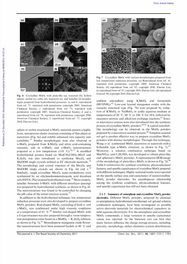
sphere or urchin structured a-MnO2 materials possess a highly
loose, mesoporous cluster structure consisting of thin plates or
nanowires (Fig. 6c) and exhibit enhanced rate capacity and
cyclability.75 Similar morphologies were also observed in
a-MnO2 prepared from KMnO4 and nitric acid-containing
reactants, and in a-MnO2 and e-MnO2 nanostructures
prepared at a low temperature (110 1C).76,77 A modified
hydrothermal process based on Mn(CH3COO)24H2O and
K2S2O8 was also introduced to synthesize Mn3O4 and
MnOOH single crystals utilized as EC electrode materials.78
The morphology and crystal structure of the Mn3O4 and
MnOOH single crystals are shown in Fig. 6d and e.78
Similarly, single crystalline Mn3O4 nano-octahedrons were
synthesized by an ethylenediaminetetraacetic acid disodium
salt (EDTA-2Na) assisted hydrothermal route.79 More recently,
lamellar birnessite d-MnO2
with different interlayer spacings
was prepared by hydrothermal synthesis, as shown in Fig. 6f.
The microstructure was found to be controlled by changing
the pH value of the initial reaction system.77
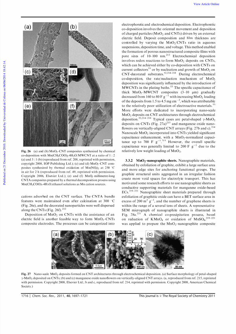
In addition to the hydrothermal technique, low temperature
reduction processes were also developed to prepare crystalline
MnO2 powders. Rod-shaped MnO2, consisting of both a- and
g-MnO2, was synthesized under high viscosity conditions
at a temperature of 65 1C.80 Similar rod-shaped MnO2 with
a d-type structure was also prepared through a room tempera-
ture precipitation route based on a MnSO4 + K2S2O8 solution,
as shown in Fig. 7a.81 Monodisperse manganese oxide flower-
like nanostructures have been prepared facilely at 40 1C and
ambient atmosphere using KMnO4 and formamide
(HCONH2).82 Low-cost layered manganese oxides with the
rancieite structural type (Fig. 7b) were prepared by reduc-
tion of KMnO4 or NaMnO4 in acidic aqueous medium at
temperatures of 20 1C, 60 1C or 100 1C for 10 h, followed by
successive proton- and alkali-ion exchange reactions.83 Sono-
or microwave sources were also introduced into the synthesis
process of crystalline MnO2 powders.84,85 A typical nanobelt-
like morphology can be observed in the MnO2 powders
prepared by a microwave-assisted process.86 Template-assisted
sol–gel is another effective way to prepare crystalline MnO2
powders with distinct morphologies. Through this technique,
Wang et al. synthesized MnO2 nanowires or nanorods with a
hollandite type a-MnO2 structure, as shown in Fig. 7c.87
Moreover, a solution combustion technique based on
Mn(NO3)2 and C2H5NO2 was developed to obtain plate-like
and spherical e-MnO2 particles. A representative SEM image
of the morphology of plate-like e-MnO2 is shown in Fig. 7d.86
Table 4 summarizes the synthesis conditions, physicochemical
features, and specific capacitances of crystalline MnO2 prepared
with different techniques. Highly scattered results were reported
on the specific surface area and capacitance of nanocrystalline
MnO2 powder electrodes. An unambiguous relationship
among the synthesis conditions, physicochemical features,
and specific capacitance has still not been obtained.
2.1.3 Summary of amorphous and crystalline MnO2 powder
electrodes. Different MnO2 powders, prepared by chemical
co-precipitation, hydrothermal/sonothermal, sol–gel and solution
combustion techniques, have been investigated as possible
active electrode materials for electrochemical capacitors in
mild aqueous electrolytes. For the amorphous and crystalline
MnO2 compounds, a large variation in specific capacitance
values was reported. In the literature one can find that
many factors influence the charge storage process, including
porosity, morphology, defect chemistry (cation distributions
Fig. 6 Crystalline MnO2 with plate-like (a), nanorod (b), hollow
sphere, urchin (c), cubic (d), nanowire (e), and lamellar (f) morpho-
logies prepared from hydrothermal processes. (a and b, reproduced
from ref. 73, reprinted with permission, copyright 2005, American
Chemical Society; c reproduced from ref. 75, reprinted with
permission, copyright 2007, American Chemical Society; d and e,
reproduced from ref. 78, reprinted with permission, copyright 2008,
American Chemical Society; f, reproduced from ref. 77, copyright
2010, Elsevier Ltd.)
Fig. 7 Crystalline MnO2 with various morphologies prepared from
low temperature reduction processes. (a) Reproduced from ref. 81,
reprinted with permission, copyright 2009, American Chemical
Society; (b) reproduced from ref. 83, copyright 2010, Elsevier Ltd.;
(c) reproduced from ref. 87, copyright 2010, Elsevier Ltd.; (d) reproduced
from ref. 86, copyright 2010, Elsevier Ltd.
View Article Online
Page 8
8/11/2019 Manganese Oxide-based Materials as Electrochemical_Wei
http://slidepdf.com/reader/full/manganese-oxide-based-materials-as-electrochemicalwei 8/25
1704 Chem. Soc. Rev., 2011, 40, 1697–1721 This journal is c The Royal Society of Chemistry 2011
and oxidation states), crystal structure, and residual water
content. It should be pointed out that there is still no standard
uniform structure and morphology available for MnO2
materials. A comparison between electrodes consisting of
various kinds of MnO2 powders is rather difficult since
MnO2 powders produced under different conditions exhibit
different structures and properties. It is believed that both
surface and bulk (crystal structure and microstructure) pheno-
mena are actively involved in the charge storage process. A
rational design to maximize the electrochemically active sites
for redox reactions through increasing BET surface area and
obtaining ‘‘opened’’ structures is important to further increase
the energy storage density of MnO2 powders.
A major disadvantage of packing MnO2 powders is the low
electronic conductivity to sustain high rate charge–discharge
processes. Hence, in a typical MnO2 powder electrode, an
electrically conductive enhancer, most commonly a high
surface area graphitic carbon, must be incorporated into the
powder electrode to improve its performance and a polymeric
binder for mechanical stability. The total amount of carbon
and organic binder (‘‘inactive’’ components) ranges from 15 to
35% in weight and up to 70% of the total electrode volume,
which will undoubtedly sacrifice the gravimetric and volumetric
energy densities of the MnO2 powder electrode. The
volumetric capacity is of interest for manufacturers as those
materials are studied with the aim of compact applications.
2.2 Thin-film MnO2 electrodes
Because of the interest for more fundamental studies and
potential applications as micro-scale energy storage systems
such as integrated devices, thin film or MnO2 coating electrodes
have been intensively explored recently. In this case, a
manganese oxide thin layer with desirable physical features
is directly assembled on a current collector through a variety
of techniques, including sol–gel dip-coating,16,33 anodic/cathodic
electrodeposition,90–92 electrophoresis,93–96 electrochemical
formation of manganese, and sputtering-electrochemical
oxidation.34
2.2.1 Sol–gel coating. Pang et al. conducted the first
research on sol–gel processing of thin film MnO2 electrodes
for EC application in 2000.16,33 Stable colloidal MnO2 was
prepared by reducing Mn(VII) (potassium permanganate)
with Mn(II) (manganous perchlorate) in an alkaline aqueous
medium,16,33 reducing tetrapropylammonium permanganate
with 2-butanol or97 adding solid fumaric acid to 0.2 M
NaMnO4,98 mixing manganese acetate with a citric acid
containing n-propyl alcohol at room temperature,99 reacting
KMnO4 with H2SO4 solutions,100,101 or reducing KMnO4 with
polyacrylamide (PAM) and polyvinyl alcohol (PVA).90
Sol–gel-derived nanoparticulate MnO2 thin films were then
formed by either dip-coating or ‘‘drop-coating’’ colloidal
MnO2 directly onto conductive substrates, followed by
calcination at various temperatures.
The calcination temperature was found to have significant
influence on the surface morphology, specific surface area, and
specific capacitance of sol–gel derived MnO2
thin films. The
highest surface areas and specific capacitances were normally
achieved by calcinating the MnO2 thin films at temperatures
ranging from 200 to 300 1C.90 The possible reason is that
calcination at proper temperatures can generate high porosity
and a well-defined pore size distribution through evaporation
of the adsorbed water, solvent, and organic molecules, but
without further densification occurring at higher temperatures.
The specific capacitance of the sol–gel derived MnO2 thin films
is also sensitive to thin film thickness. For instance, the
ultrathin MnO2 deposits (tens to hundreds of nanometres
thick) deliver specific capacitances as high as 700 F g1.90
The specific capacitance for thicker MnO2 films, i.e., higher
Table 4 Synthesis conditions, physicochemical features, and subsequent specific capacitance of crystalline MnO2
Technique Synthesis conditions Morphology Structure S BET/m2 g1 C /F g1
Hydrothermal MnSO4H2O+ KMnO4,140 1C73,74
Plate-like, nanorods a-MnO2 100–150 72 to 168(200 mA g1)
Hydrothermal KMnO4 + sulfuric acid andCu scraps, 110 1C75
Hollow spheres,hollow urchins
a-MnO2 52–108 147 (5 mV s1)
Hydrothermal KMnO4 + nitric acid, 110 1C76 Urchin-like a-MnO2 80–119 86–152 (5 mV s1)Hydrothermal MnSO4 + K2S2O8 + sulfuric acid,
110 1C88
Urchin-like, clew-like a-MnO2, e-MnO2 — 46–120 (5 mV s1)
Hydrothermal Mn(CH3COO)2 + K2S2O8, 120 1C78 Cubes and nanowires Mn3O4, MnOOH — B170 (500 mV s1)Hydrothermal a-NaMnO2 + nitric acid, 120 1C77 Lamellar d-MnO2 — 241 (2 mA cm2)High viscosityprocess
KMnO4 + MnCl2 + PG + PAM,65 1C80
Rod-shaped a-MnO2, g-MnO2 — 389 (10 mV s1)
Room temperatureprecipitation
MnSO4 + K2S2O881 Rod-shaped d-MnO2 — 201
Low temperaturereduction
KMnO4 + formamide, 40 1C82 Nanoflower Cubic MnO2 (Fd 3m) 225.9 121.5 (1000 mA g1)
Low temperaturereduction
KMnO4 or NaMnO4 in acidsat 20–100 1C83
Layered Rancieite structure 11–206 17–112 (2 mV s1)
So noc hemistry KB rO3 + MnSO4 + 24 kHzultrasound84,85
Spherical particles g-MnO2 — 118–344
Microwave-assistedemulsion
KMnO4 + oleic acid + microwave88 Belt-like d-MnO2 — 277 (0.2 mA cm2)
Sol–gel process Manganese acetate + citric acid,80 1C89
Nanorods g-MnO2 — 317 (100 mA g1)
Solution combustion Mn(NO3)2 + C2H5NO286 Plate-like e-MnO2 23–43 71–123
(1000 mA g1)
View Article Online
Page 9
8/11/2019 Manganese Oxide-based Materials as Electrochemical_Wei
http://slidepdf.com/reader/full/manganese-oxide-based-materials-as-electrochemicalwei 9/25
This journal is c The Royal Society of Chemistry 2011 Chem. Soc. Rev., 2011, 40, 1697–1721 1705
mass loading, is generally limited to 100–200 F g1, which
confirms that only a thin layer of MnO2, an electrochemically
active layer, is involved in the redox process.90
2.2.2 Anodic electrodeposition. Anodic electrodeposition
involves oriented diffusion of charged reactive species through
an electrolyte when an electric field is applied, and oxidation of
the charged species on the deposition surface that also serves
as an electrode. For the anodic electrodeposition of thin film
MnO2, the electro-oxidation of Mn(II) species occurs on the
anode surfaces, shown as follows:
Mn2+ + 2H2O - MnO2 + 4H+ + 2e (5)
Pang et al. potentiostatically prepared the first electro-
deposited thin film MnO2 electrode for ECs in 2000.90 This
was followed by more than 30 papers dealing with anodic
electrodeposition of manganese dioxide thin film electrodes used
in ECs.35,91,92,102–143 Most of these studies focused on varying
the deposition parameters to obtain MnO2 thin films with a wide
range of water contents, oxidation states, and Brunauer–
Emmett–Teller (BET) surface areas and, in turn, to achieveenhanced electrochemical performance, e.g., high capacitance,
long-term cycling behavior, and fast charge/discharge rates.
Electrode materials with three-dimensional (3D), meso-
porous and ordered/periodic architectures are desirable for
the penetration of electrolyte and reactants into the entire
electrode matrix. Among the efforts, therefore, morphology-
controlled growth has attracted much interest to obtain
more accessible electroactive sites and shorter cation
diffusion lengths in MnO2 electrodes. Morphology-controlled
growth is generally achieved through controlling the
deposition parameters, filling template membranes, or using
etched, nanoporous substrates. In the first case, the most
common surface morphology in MnO2 electrodes throughgalvanostatic or potentiostatic modes is a porous, three-
dimensional (3D) fibrous network, as shown in
Fig. 8a.33,102,108,110,115,116,118,119,125,128,130–132 Another type of
surface morphology through a template-free process is free-
standing micro- and nano-scale fibers, rods and interconnected
nanosheets prepared either by using a dilute electrolyte
(Fig. 8b–d)134,135 or applying cyclic voltammetry (Fig. 8e
and f).35,108,118 In the second case, anodic Al oxide (AAO)
templates or lyotropic liquid crystalline (LLC) phases are
applied to direct the MnO2 deposition.120,129,133,136 MnO2
electrodes with oriented nanofibrous, nanotubular and
mesoporous ravine-like morphologies are attained, as shown
in Fig. 9.
120,129,133,136
For electrodeposition on etched, nano-porous substrates, selective dissolution of copper (Cu) from a
Ni–Cu alloy layer is conducted to obtain a nanoporous Ni
substrate, followed by anodic electrodeposition of MnO2.138
Schematic illustrations for preparing a high-porosity Mn oxide
electrode are depicted in Fig. 10a.138 Fig. 10b–d show SEM
micrographs of the as-deposited Ni–Cu alloy film, the nano-
porous Ni film, and the high-porosity Mn oxide electrode.138
This idea was also applied to obtain high-porosity Mn oxide
deposits based on micro-etched duplex stainless steel (DSS).139
2.2.3 Cathodic electrodeposition. Cathodic deposition of
manganese oxide thin films can be realized through two
electrochemical processes, depending on the reactions taking
place at the cathode surfaces. One method is electrogenera-
tion of the base, including reactions that consume H+
ions
Fig. 8 Typical surface morphologies for MnO2 electrodes prepared
through template-free anodic electrodeposition processes. (a) Reproduced
from ref. 106, reprinted with permission. Copyright 2003, The
Electrochemical Society; (b) reproduced from ref. 134, reprinted with
permission. Copyright 2010, Elsevier Ltd.; (c) and (d) reproduced from
ref. 135, reprinted with permission. Copyright 2010, Elsevier Ltd.;
(e) reproduced from ref. 118, reprinted with permission. Copyright
2007, Elsevier Ltd.; (f) reproduced from ref. 35, reprinted with
permission. Copyright 2005, American Institute of Physics.
Fig. 9 MnO2 nanostructures prepared by template-assisted
anodic electrodeposition. (a) Reproduced from ref. 133, reprinted
with permission. Copyright 2009, The Royal Society of Chemistry;
(b) reproduced from ref. 120, reprinted with permission. Copyright
2006, Elsevier Ltd.; (c) reproduced from ref. 136, reprinted with
permission. Copyright 2010, Elsevier Ltd.; (d) reproduced from
ref. 129, reprinted with permission. Copyright 2008, Elsevier Ltd.
View Article Online
Page 10
8/11/2019 Manganese Oxide-based Materials as Electrochemical_Wei
http://slidepdf.com/reader/full/manganese-oxide-based-materials-as-electrochemicalwei 10/25
1706 Chem. Soc. Rev., 2011, 40, 1697–1721 This journal is c The Royal Society of Chemistry 2011
or electrolysis of water. These reduction reactions cause an
increase in the pH of the electrolyte adjacent to the cathode,
either by the consumption of H+ ions or the generation of
OH ions, which compete with the metal ion reduction reac-
tion and become the overriding reactions. As a result, metal
deposition does not take place; instead the metal ion deposits
in the form of a hydroxide on the cathode as:
Mn2+ + 2(OH) = Mn(OH)2k (6)
Subsequent thermal annealing will convert the manganesehydroxide into stable manganese oxides by a dehydration
process. Zhitomirsky et al. fabricated very smooth and amorphous
MnOx films for electrochemical supercapacitors from poly-
ethylenimine (PEI)– or chitosan–MnCl2 solutions, as shown in
Fig. 11a.91,92 A similar cathodic process based on manganese
acetate-containing solutions was developed to prepare Mn3O4
films with a porous/nanoflake hierarchical architecture
(Fig. 11b).140
The other cathodic process involves electro-reduction of
Mn(VII) species occurring on the cathode surfaces as
MnO4 + 2H2O + 3e- MnO2 + 4OH (7)
This reaction was employed for the fabrication of nano-
structured manganese dioxide films by galvanostatic, pulse,
and reverse pulse electrodeposition.141–145 The deposition rate,
composition, and microstructure of the deposits are dependent
on the concentration of active MnO4 species. Electrodeposition
from a relatively dilute solution containing 0.02 M NaMnO4
resulted in the formation of fibrous films with a birnessite-
type crystal structure, while smoother and amorphous
films were obtained using 0.1 M NaMnO4 solutions.141–145
Typical surface morphologies of electrodeposited MnO2
films prepared under different conditions are compared in
Fig. 11c and d.143
2.2.4 Electrochemical oxidation of Mn films. Broughton
et al. developed a new procedure making use of physical vapor
deposition (PVD) with a glancing vapor incidence angle
(GLAD) in order to produce a chevron-type porous Mn
metallic structure, which was then electrochemically oxidized
to produce a manganese oxide electrode for ECs.34,146–150
The
primary concept of thin-film structural control using GLAD
deposition relies on self-shadowed columnar growth that is
manipulated by angular and rotational control of the substrate
with respect to the evaporation source during the deposition.34
Metallic manganese films were deposited using the GLAD
deposition apparatus, as shown schematically in Fig. 12a.34
Fig. 12b and c show the typical as-deposited chevron-type Mn
metallic film (Fig. 12b)147 and electrochemically oxidized
petal-shaped MnO2 (Fig. 12c).149 The porous chevron-type
structure has been converted into thin sheet-like, hydrated
MnO2. In addition to the electrochemical oxidation process,
the chevron-type Mn metallic films were also thermally
oxidized in air to obtain manganese oxide layers. In this case,
the zig-zag architecture was replaced by a porous oxide
structure with little zigzag texture remaining, as shown in
Fig. 12d.147 The specific capacitance obtained from the
electrochemically oxidized manganese films was generally
higher than that from thermally oxidized samples, which
further confirms that the electrochemically active sites in
manganese oxide are closely related to a hydrated and porous
structure.148
In addition to the GLAD deposition process, an electro-
chemical deposition process was also developed to deposit metallic
manganese films from a BMP–NTf 2 ionic liquid.151–153 The
electrodeposited Mn films (Fig. 13a) were anodized in Na2SO4
aqueous solution by various electrochemical methods such
as potentiostatic, galvanostatic, and cyclic voltammetry (CV),
and transformed to Mn oxides with different physical charac-
teristics, as shown in Fig. 13b–d.151 The Mn oxide anodized
Fig. 10 (a) Schematic for preparing a high-porosity Mn oxide
electrode based on micro-etched conductive substrates, (b)–(d) SEM
micrographs of the as-deposited Ni–Cu alloy film, nanoporous Ni
film, and high-porosity Mn oxide electrode. (Reproduced from
ref. 138, reprinted with permission. Copyright 2008, Elsevier Ltd.)
Fig. 11 Cathodic deposition of manganese oxide thin films based on
different cathodic reactions. (a) and (b) Electrogeneration of base;
(c) and (d) electro-reduction of Mn(VII) species. (a, reproduced from
ref. 91, reprinted with permission. Copyright 2006, Elsevier Ltd.; b,
adapted from ref. 140, reprinted with permission. Copyright 2009, The
Electrochemical Society; c and d, reproduced from ref. 143, reprintedwith permission. Copyright 2008, Institute of Materials, Minerals and
Mining.)
View Article Online
Page 11
8/11/2019 Manganese Oxide-based Materials as Electrochemical_Wei
http://slidepdf.com/reader/full/manganese-oxide-based-materials-as-electrochemicalwei 11/25
This journal is c The Royal Society of Chemistry 2011 Chem. Soc. Rev., 2011, 40, 1697–1721 1707
under the CV condition had the largest surface area, highest
hydrous state, and lowest Mn valence state and showed thehighest specific capacitance.
2.2.5 Electrophoretic deposition. Another electro-assisted
coating technique is electrophoretic deposition (EPD). EPD is
achieved through the motion of charged particles in suspen-
sions towards an electrode and deposition under an external
electric field. Bath compositions for EPD include various
additives, which provide stabilization and charging of inorganic
particles in the suspensions. The electrophoretic deposition of
MnO2 films involves a two-step process: firstly, a stable
suspension of charged MnO2 particles is prepared by the
reduction of KMnO4 aqueous solutions with various reducing
agents. Electrophoretic deposits are subsequently obtained
under potentiostatic or galvanostatic conditions.93–96 The
deposition variables can be voltage or current density, solution
concentration, pH value, and solution temperature, but the
physicochemical features of EPD MnO2 films are primarily
dictated by the formation process of charged MnO2 suspen-
sions. Highly porous thin films containing nanofibers and
equiaxed particles are prepared through manipulation of the
formation parameters of charged MnO2 suspensions, as
shown in Fig. 14.95,96 Comparable electrochemical properties
(specific capacitance and cycle life) are obtained from the EPD
MnO2 films.
2.2.6 Summary on the development of thin film MnO2
electrodes
The fundamentals and technique approaches in synthesizing
thin film or MnO2
coating electrodes have been summarized in
this chapter. Four groups of coating synthesis methods,
including sol–gel, electrochemical deposition, electrochemical
oxidation of metallic Mn films, and electrophoretic deposition,
have been reviewed and discussed in detail. Sol–gel techniques
involve either dip-coating or drop-coating colloidal MnO2
directly onto conductive substrates, followed by calcination
at various temperatures. Calcination at elevated temperatures,
however, limits the types of substrate materials and the scope
of phase structures in which MnO2 nanostructures can be
deposited. By contrast, electrochemical deposition and electro-
phoretic deposition are two room temperature techniques,
opening up the prospect of deposition on various inexpensive
substrates including plastic substrates. Electrophoretic deposi-
tion is achieved through the motion of charged particles in
suspensions and deposition on the electrode surfaces. In this
case, the MnO2 particles are prepared before electrophoretic
deposition, so this technique itself cannot change the physico-
chemical characteristics of the MnO2 phase. The electro-
chemical deposition technique has some distinct advantages
for growing nanostructured electrode materials. It is generally
applicable to obtain metallic-, oxide-, and polymer-based
nanostructured materials. The composition, defect chemistry,
and even crystal structure can be manipulated through adjusting
solution concentration, solution pH value, and applied over-
potential or current density.
Fig. 12 (a) Schematic illustration of evaporation source and substrate
geometry during GLAD deposition of Mn films; (b) as-deposited
chevron-type Mn metallic films; (c) chevron-type Mn metallic films
after full electrochemical oxidation; (d) chevron-type Mn metallic films
after full thermal oxidation. (a, adapted from ref. 34, reprinted with
permission. Copyright 2002, The Electrochemical Society; b and d,
reproduced from ref. 147, reprinted with permission. Copyright 2003,
Kluwer Academic Publishers; c, adapted from ref. 149, reprinted with
permission. Copyright 2006, The Electrochemical Society.)
Fig. 13 SEM micrographs of (a) as-deposited Mn, (b) Mn oxide—
potentiostatic electrode, (c) Mn oxide—galvanostatic electrode, and
(d) Mn oxide—cyclic voltammetry electrode. (Reproduced from
ref. 151, reprinted with permission. Copyright 2008, Elsevier Ltd.)
Fig. 14 Highly porous thin films containing nanofibers (a) and
equiaxed particles (b) prepared through manipulating the forma-
tion parameters of charged MnO2 suspensions. (a, reproduced from
ref. 95, reprinted with permission. Copyright 2008, Elsevier Ltd.;
b, reproduced from ref. 96, reprinted with permission. Copyright
2009, Elsevier Ltd.)
View Article Online
Page 12
8/11/2019 Manganese Oxide-based Materials as Electrochemical_Wei
http://slidepdf.com/reader/full/manganese-oxide-based-materials-as-electrochemicalwei 12/25
1708 Chem. Soc. Rev., 2011, 40, 1697–1721 This journal is c The Royal Society of Chemistry 2011
3. MnO2-based composite electrodes with other
elements and conducting polymers
Poor electrical conductivity (B105 O cm) has been reported
for micrometre-thick birnessite-type MnO2.55 The specific
capacitance and power characteristics of MnO2 electrodes
are ultimately limited by the high charge-transfer resistance.
It is well established that the transition metal oxides are
semiconducting in nature. Incorporation of other metal elements
into MnO2 compounds is a potential route to enhance the
electrical conductivity and charge-storage capability of
manganese oxides by introducing more defects and charge
carriers. The other consideration for alleviating the poor
electronic conductivity of MnO2 electrodes is to tailor the
electrode architecture, i.e., applying an ultrathin layer of MnO2
on the surface of a porous, high surface area and electronically
conducting structure to shorten the electron transport distance.
This can produce good electrochemical performance without
sacrificing the mass-loading of the MnO2 phase. The porous
architectures can be carbon nanofoams, templated mesoporous
carbon, and nanotube assemblies.
In addition to their poor electrical conductivity, another
important issue is the electrochemical cyclability of MnO2
electrodes. Active material dissolution during electrochemical
cycling has been well recognized in some investigations,16,33,130,131
which accounts for the major capacitance loss of the MnO2
electrodes. A direct route to protect active MnO2 material
from electrochemical dissolution is to apply a coating on the
MnO2 nanoarchitecture as an effective barrier to Mn cation
permeation while allowing the electrolyte to be accessible.
Mechanical issues, such as low structural stability and flexibility,
also exist in MnO2 electrodes resulting in degraded long-term
electrochemical cycle life. Hsieh et al . reported that capaci-
tance fading can be attributed to gradual mechanical failure of
the electrode materials caused by cyclic volumetric variations
of the oxide particles upon cycling.154 To enhance the mecha-
nical stability and flexibility, many efforts have also been
attempted to incorporate conductive polymers (polyaniline,
polypyrrole, and polythiophene) and their derivatives to get
mixed MnO2 –polymer composite electrodes with desirable
morphologies.56–59 The excellent electronic conductivity, high
stability and mechanical flexibility of applied conductive polymers
enable improved electrochemical and mechanical properties of
MnO2 –polymer composite electrodes for ECs.56–59
3.1 MnO2 –MeOx
composite electrodes
3.1.1 Mn–Ni mixed oxide compounds. Nickel oxides made
by the sol–gel method or electrochemical oxidation have been
evaluated as active materials for ECs, but they normally
exhibit low specific capacitances of 50–64 F g1.155,156 Mn–Ni
mixed oxide electrodes for EC application were first synthesized
through reduction of KMnO4 with Ni(II) acetate–manganese
acetate reducing solutions.44 Another chemical route, based
on thermal decomposition of the precursor obtained by
chemical co-precipitation of Mn and Ni transition metal salts,
was also developed to prepare Mn–Ni and Mn–Ni–Co oxide
composites.157,158 By introducing 20% NiO into MnO2, the
specific capacitance increased from 166 F g1 for MnO2 to
210 F g1 for the Mn/Ni mixed oxide. A higher rate capacity
was also observed for the Mn/Ni mixed oxides, and the
enhanced properties were attributed to the increased surface
area of the mixed oxide due to the formation of micropores.44
Electrochemical co-deposition of Mn/Ni mixed oxides from
Mn(II) and Ni(II) containing solutions was also applied toprepare thin film electrodes. The rate of anodic deposition for
manganese oxide is much larger than that for Ni oxide under
potentiostatic conditions, as shown in the linear sweep
voltammograms in Fig. 15a.38 The Ni content of binary
Mn–Ni oxide electrodes is raised by applying a relatively
positive potential and a high Ni2+/Mn2+ ratio (e.g., 10 : 1)
during co-deposition. Addition of Ni oxide into the MnO2
electrodes changed the shape of the grains from spherical into
flat, as shown in Fig. 15b and c, but a similar fibrous feature
was maintained at higher magnification.38 The a-(Mn,Ni)xO y
with B18 wt% Ni showed higher capacity, better electro-
chemical reversibility, and high-power characteristics in a
mixed electrolyte consisting of Na2SO4 and NaOH withpH of 10.1.
38
Potentiodynamic methods are another effective electro-
chemical strategy to realize co-deposition of nanostructured
and microporous nickel–manganese oxides onto inexpensive
stainless steel substrates.39 A scan rate of 200 mV s1 between
the potential limits of 0.0 and 1.4 V was employed for the
deposition. At high scan rates, the deposition rate is low, and
accordingly, more than 300 cycles were required to deposit the
required amount of manganese–nickel oxides with an atomic
ratio of 65 : 35. Enhanced electrochemical properties were
observed in this type of mixed oxide electrode. For instance,
specific capacitance (SC) values of 621 F g1 and 377 F g1
were obtained for CV scan rates of 10 and 200 mV s1
,respectively.39 These values of electrochemical performance
are much higher than those obtained with just MnO2. Since
the mass loading of the manganese–nickel oxides was not
reported, it is difficult to compare with other systems.
3.1.2 Mn–Co mixed oxide compounds. Cobalt oxides are
another candidate material for electrochemical supercapacitor
applications.8,159–161 However, it is noted that cobalt oxides
have a narrower operation potential window of approximately
0.5 V and require a basic working electrolyte for supercapacitor
applications, compared with manganese oxide-based electrode
materials. Incorporation of Co oxides in Mn oxides has been
Fig. 15 (a) Linear sweep voltammograms measured at 2 mV s1
in (1) 0.01 M MnCl2 and (2) 0.1 M NiCl2; SEM micrographs of
(b) a-MnOxnH2O and ( c) a-(Mn,Ni)xO ynH2O. (Adapted from
ref. 38, reprinted with permission. Copyright 2002, The Electro-
chemical Society.)
View Article Online
Page 13
8/11/2019 Manganese Oxide-based Materials as Electrochemical_Wei
http://slidepdf.com/reader/full/manganese-oxide-based-materials-as-electrochemicalwei 13/25
This journal is c The Royal Society of Chemistry 2011 Chem. Soc. Rev., 2011, 40, 1697–1721 1709
attempted to further improve their pseudocapacitive performance.
Prasad and Miura deposited nanostructured and microporous
cobalt–manganese oxide (CMO) onto inexpensive stainless
steel substrates by potentiodynamic methods, and found that
addition of Co oxide has a beneficial impact on improving
specific capacitances of MnO2.39 Similar improvement in
electrochemical properties of Co–Mn oxides was observed in
another study.162 However, neither the corresponding
physicochemical features were characterized nor was the
electrochemical mechanism addressed.
Some other studies using potentiostatic deposition of mixed
Mn–Co oxides exhibited different tendencies. For instance,
Chuang and Hu investigated the effects of solution pH values
on the surface morphology and chemistry of as-deposited
mixed Mn–Co oxides.163 Adjusting the pH of the plating
solution varied the surface morphology and Co/Mn content
ratio in the deposited oxides, but the specific capacitance
of these oxides essentially remained unchanged.163 By
contrast, Chang et al. reported that the addition of Co oxides
modified the oxide surface from a fibrous shape to a rather
smooth morphology (Fig. 16a and b), which may account
for the significant reduction in the specific capacitance of the
as-deposited mixed Mn–Co oxide with a high Co content
(>15 wt%) (Fig. 16c).164,165 However, the addition of Co
oxides effectively inhibited the irreversible anodic dissolution
of the deposited oxide during electrochemical cycling in
aqueous KCl electrolyte (Fig. 16d).164,165 This suggests a great
improvement in electrochemical stability for mixed Mn–Co
oxide electrodes.
In addition to electrochemical routes, a radio-frequency
sputtering procedure was used to prepare manganese–cobalt
oxide thin films.166 Through the control of the flow rate of
oxygen, sputtering pressure, sputtering power, and annealing
temperature, mixed oxide layers with petal-shaped morpho-
logy were obtained, as shown in Fig. 17.166 A maximum
specific capacitance of 256 F g1 was retained at the 2000th
cycle of potential cycling, demonstrating long-term operational
stability and good specific capacitance at a high sweep rate of 100 mV s1.166
3.1.3 Mn–Fe mixed oxide compounds. Iron possesses
various valence states making it a promising electrode material
for supercapacitors. MnFe2O4, a Mn–Fe mixed oxide material,
was recently found to exhibit pseudocapacitance in aqueous
NaCl solutions. MnFe2O4 was synthesized via a precipitation
technique in basic aqueous solutions with a MnSO4 to FeCl3ratio of 2 : 1, followed by a subsequent calcination process at
different temperatures for 2 h in a N2 atmosphere.167 It was
found that large capacitances are associated with the Mn2+
ions in the tetrahedral sites in the spinel structure. Pseudo-
capacitance was observed only for crystalline, rather than
amorphous MnFe2O4 treated at temperatures o 200 1C, as
shown in the cyclic voltammograms (Fig. 18) taken from Mn–Fe
mixed oxide electrodes annealed at different temperatures.167
This tendency is essentially different from what was observed
for MnO2 electrodes, but a clear understanding has not been
reached yet.
Another technique to incorporate iron oxides into manga-
nese oxide electrodes is electrochemical co-deposition.168–170
Mn–Fe oxides were prepared on graphite substrates by anodic
deposition from 0.25 M Mn acetate aqueous solutions with
various amounts of FeCl3 up to 0.15 M.168–170 Experimental
results indicated that the incorporated iron was present as
di- and tri-valent oxides. In situ X-ray absorption spectroscopy
(XAS) results (Fig. 19) confirm that the pseudocapacitive
behavior of the Mn–Fe oxides is associated with the reversible
variations in the oxidation states of both the Mn and Fe
cations during electrochemical cycling.170 It has been found
that through introduction of Fe oxide, the degree of change in
the Mn oxidation state increases from 0.70 to 0.81 within the
potential range of 0–1 V. The specific capacitance of Mn90Fe10oxide (255 F g1) is higher than that of the pure Mn oxide
(205 F g1). This experimental evidence suggests that Fe
addition enhances the electrochemical performance through
improving the electrical conductivity of manganese oxides.170
Fig. 16 (a) and (b) SEM micrographs of the oxides deposited in
Mn(CH3COO)2 plating solutions with 0 and 0.2 M Co(CH3COO)
additions; (c) cyclic voltammograms of the various oxide electrodes
measured in 2 M KCl electrolyte at a potential scan rate of 5 mV s1;
(d) variations in the specific capacitance vs. the CV cycle number for
various oxide electrodes. Curves a–e present the oxides deposited with
0, 0.05, 0.1, 0.15, and 0.2 M Co(CH3COO)2 additions, respectively.
(Adapted from ref. 164, reprinted with permission. Copyright 2008,
Elsevier Ltd.)
Fig. 17 SEM micrograph of the Mn–Co oxide electrode prepared by
radio-frequency sputtering. (Adapted from ref. 166, reprinted with
permission. Copyright 2010, The Electrochemical Society.)
View Article Online
Page 14
8/11/2019 Manganese Oxide-based Materials as Electrochemical_Wei
http://slidepdf.com/reader/full/manganese-oxide-based-materials-as-electrochemicalwei 14/25
1710 Chem. Soc. Rev., 2011, 40, 1697–1721 This journal is c The Royal Society of Chemistry 2011
A two-step spray pyrolysis-electrophoretic deposition
(SP-EPD) process was employed to prepare nanocrystalline
Mn–Fe mixed oxide electrodes.171 The iron-containing
manganese oxide powders were synthesized from manganese
acetate and iron nitrate solutions at 400 1C. The as-processed
powders were subsequently deposited onto graphite substrates
via electrophoretic deposition. Structural analysis revealed
that the as-deposited coatings exhibited a nanocrystalline
Mn3O4 phase. The specific capacitance of the as-deposited
Mn-oxide coating was increased from 202 F g1 to 232 F g1
when 2 at% Fe was added.171 Moreover, enhanced electro-
chemical cyclability was observed for the iron-added coatings
(B78% of the initial maximum capacitance) compared with a
pure MnO2 electrode (B60% of its maximum value).171
3.1.4 Mn–X (X = Pb, V, Ru, Mo and Al) mixed oxides. In
addition to Ni, Co and Fe, other metallic elements have been
introduced with the intention to further improve the electro-
chemical performance of Mn oxide electrodes. Lead oxides
were added into Mn oxide electrodes through reduction of
KMnO4 with Pb(II) acetate–manganese acetate reducing
solutions.44 By introducing 20% Pb into MnO2, the specific
capacitance increased from 166 F g1 estimated for MnO2 to
185 F g1 for Mn/Pb mixed oxides, which was attributed to
the increased surface area of the mixed oxide due to the
formation of micropores.44
Vanadium oxide (V2O5) was introduced into MnO2 thin
film electrodes by electro-oxidation of Mn2+ precursors in
aqueous solution with VO3.40,172 XRD analysis confirmed
that the presence of vanadate ions inhibits the growth of the
Mn oxide lattice, leading to an amorphous-like phase in the
as-deposited mixed Mn–V oxide.40,172 The infrared spectrum
exhibited bands attributable to V2O5, suggesting that protona-
tion and dehydration of VO3 – occur to form the polymeric
structure. The electron spin resonance results suggest that
Mn3+ ions do not exist in the oxide network, but pair with
unreacted VO3.40,172 When annealed at elevated tempera-
tures, the formation of Mn2+ occurs only in the mixed Mn–V
oxide films. This implies that electron transfer from thermally
generated V4+ cations to neighboring Mn cations occurs.40,172
Enhanced voltammetric response of the heat treated Mn/V
oxide film was observed in a borate solution, compared with
that of pure manganese oxide, which can be attributed to the
higher electrical conductivity of the mixed Mn–V oxide
films.40,172
Ruthenium–manganese oxide (RunMn1nOx) has been
prepared by oxidative co-precipitation through mixing of Mn(VII)
(potassium permanganate), Mn(II) (manganese acetate), and
Fig. 18 CV curves of coprecipitated electrodes consisting of MnFe2O4/carbon black powders treated at different temperatures: (a) 50 1C and
200 1C, (b) 300 1C, 350 1C, 400 1C and 500 1C. Scan rate was 20 mV s1. (Adapted from ref. 167, reprinted with permission. Copyright 2005,
The Electrochemical Society.)
Fig. 19 (a) Twenty-one serial in situ Mn–K edge XAS spectra for Mn90Fe10 oxide measured at various applied potentials. (b) The dependence of
the Mn oxidation state with respect to the applied potential, obtained from (a). (Adapted from ref. 170, reprinted with permission. Copyright 2008,
Elsevier Ltd.)
View Article Online
Page 15
8/11/2019 Manganese Oxide-based Materials as Electrochemical_Wei
http://slidepdf.com/reader/full/manganese-oxide-based-materials-as-electrochemicalwei 15/25
This journal is c The Royal Society of Chemistry 2011 Chem. Soc. Rev., 2011, 40, 1697–1721 1711
Ru(III) (ruthenium chloride) in a neutral aqueous solution at
room temperature.42 The proposed formation reactions are as
follows:42
2MnO4 + 3Mn2+ + 2H2O - 5MnO2 + 4H+ (8)
Ru3+ + 3H2O - Ru(OH)3 + 3H+ (9)
4Ru(OH)3
+ O2- 4RuO
2 + 6H
2O (10)
At an appropriate calcination temperature (e.g., 170 1C), the
mixed Ru–Mn oxide powders are in a hydrous amorphous
state with improved electrochemical properties (higher specific
capacitance and lower charge transfer resistance, as shown in
the CV curves in Fig. 20a and impedance spectra in Fig. 20b),
when compared with pure Mn oxide.42 The reduced charge
transfer resistance and enhanced voltammetric response observed
in the mixed Ru–Mn oxide powders can be attributed to a
higher electronic conductivity induced by the Ru-doping.
In addition to chemical co-precipitation, a co-electrospinning
technique was employed to synthesize MnOx –RuO2 composite
fiber mats through two isolated spinnerets.173 During the
electrospinning process, two types of precursor solutions,
based on Mn acetylacetonate + PVAc and RuCl3 + PVAc,
were transferred simultaneously into separate syringes
mounted on the electrospinning apparatus, as schematically
shown in Fig. 21a.173 The as-electrospun and calcinated
MnOx –RuO2 fiber mats at different temperatures are shown
in Fig. 21b–d. The electrochemical performance using the
co-electrospun MnOx –RuO2 fiber mats calcined at 300 1C
exhibited a high specific capacitance of 208.7 F g1 at a scan
rate of 10 mV s1.173 The co-electrospinning technique shows
high versatility to preparing composite electrodes with both
high surface activity and high conductivity for EC applications.
Mn–Mo mixed oxide thin films were deposited anodically
on a platinum substrate by cycling the electrode potential
between 0 and +1.0 V vs. Ag/AgCl in aqueous Mn(II) solutions
containing molybdate anions (MoO42).43 In this process,
only Mn(II) cations were electro-oxidized to form MnO2.
The MoO42 ions were incorporated into MnO2 by protona-
tion and dehydration,43 which is similar to the formation
of MnO2 –V2O5 mixed oxides mentioned above.40,172 Cyclic
voltammetry of the Mn/Mo oxide electrode in an aqueous
0.5 M Na2SO4 solution exhibited pseudocapacitive behavior
with a higher capacitance and better rate capability than that
for pure Mn oxide, most likely due to an increase in electrical
conductivity of the mixed oxide film.43
Aluminium (Al) is another element that has been added into
manganese oxide electrodes.45,174 Al-doped MnO2 compounds
were synthesized either by an electrochemical–hydrothermal
route45,174 or through a high energy ball-milling technique.45,174
The electrochemical–hydrothermal technique can be regarded
as anodic electrodeposition in an autoclave at solution tempera-
tures ranging from 80 1C and 140 1C.45,174 The Al-substituted,
g-MnO2 materials exhibited a higher specific capacitance than
non-substituted MnO2, consistent with the beneficial effect of
substitution on the surface area.45,174 For high energy ball-
milling, a mixture of pure aluminium and manganese dioxide
powder with a desired atomic ratio was put into a stainless
steel vessel with steel balls at a ball-to-powder weight ratio of
20 : 1. The high energy ball-milling was conducted at 250 rpm
for 50 h. The Al(0.05)/Mn(0.95)O2 electrode showed the largest
Fig. 20 (a) Cyclic voltammograms and (b) Nyquist plots for RunMn1nOx (n = 0.1) and MnO2 electrodes at different applied potentials in the
frequency range of 102 –104 Hz. Both powders were calcined at 170 1C. (Adapted from ref. 42, reprinted with permission. Copyright 2009, Elsevier
Ltd.)
Fig. 21 (a) Schematic diagram of the co-electrospinning process used
to synthesize MnOx –RuO2 fiber mats. (b) SEM image of as-spun
MnOx –RuO2/PVAc composite fiber mats prepared by electrospinning.
(c) SEM image of MnOx –RuO2 fiber mats calcined at 300 1C. (d) SEM
image of MnOx –RuO2 fiber mats calcined at 400 1C. (Adapted from
ref. 173, reprinted with permission. Copyright 2009, The Electro-
chemical Society.)
View Article Online
Page 16
8/11/2019 Manganese Oxide-based Materials as Electrochemical_Wei
http://slidepdf.com/reader/full/manganese-oxide-based-materials-as-electrochemicalwei 16/25
1712 Chem. Soc. Rev., 2011, 40, 1697–1721 This journal is c The Royal Society of Chemistry 2011
specific capacitance among the MnO2 samples with various Al
contents.45,174 Excellent electronic conductivity for Al doped
MnO2 was considered to be responsible for the enhanced
electrochemical performance of doped MnO2.45,174
3.1.5 Summary of incorporation of other metal elements in
MnO2. A core challenge in EC design is the identification
of suitable electro-active materials. The poor electrical con-
ductivity of MnO2 limits the specific capacitance and power
characteristics of MnO2 electrodes through high charge-
transfer resistance. Metal elements, including Ni, Fe, Co,
V, Mo, Al, Pb, and Ru, can be incorporated into MnO2
compounds to enhance the electrical conductivity and
charge-storage capability by introducing more defects and
charge carriers. Enhancement of specific capacitance was
observed for Ni-, Fe-, V-, Mo-, Al-, Pb-, and Ru-containing
MnO2 electrodes, and was mainly attributed to the improved
electrical conductivity of the composite electrodes. The
amount of metal additives has significant effects on the
electrochemical properties. For instance, for Mn–Fe mixed
oxides, the specific capacitance increases with addition of Fe
oxides and reaches a maximum value at a Mn : Fe ratio of
9 : 1. A further increase in the amount of Fe oxide may cause a
reduction in the specific capacitance.170 However, contradictory
results have been reported for the effect of Co oxide additions
on the specific capacitance of MnO2 electrodes. Some research
work exhibited beneficial effects by introducing Co oxides,
whereas other studies showed an opposite tendency.39,162 It is
interesting to note that the addition of Co oxides may signifi-
cantly suppress the irreversible dissolution of the deposited
oxide during electrochemical cycling in aqueous KCl electro-
lyte, resulting in a great improvement in the electrochemical
stability of mixed Mn–Co oxide electrodes. Thus far, however,
an unambiguous understanding on the effect of introducing
metal elements to form mixed oxide electrodes on the sub-
sequent electrochemical properties is lacking, which is critical
to optimizing manganese oxide-based electrodes for EC
application.
Note that similar chemical modification routes have been
extensively applied to improve the electrochemical properties
of MnO2-based batteries such as Li/MnO2. Layered LiMnO2
and spinel LiMn2O4 are the most attractive positive electrode
materials for the Li/MnO2 batteries. Layered LiMnO2 has
high theoretical capacity but poor capacity retention induced
by structural instability (phase transition from the layered
structure to spinel).175,176 Partial substitution of Mn with Co
or Ni has been employed to improve the electrochemical
reversibility of layered LiMnO2 electrodes.175,177–179 For the
stable spinel LiMn2O4, on long term cycling, slight capacity
fading was also observed in the Li/MnO2 batteries, which was
attributed to slow dissolution of the LiMn2O4 electrode in
the electrolyte and the onset of the Jahn–Teller distortion
for a deeply discharged LiMn2O4 electrode.180–182 There are
various strategies to alleviate or eliminate the dissolution
and Jahn–Teller distortion issues, including the substitution
of Jahn–Teller ion Mn3+ by some other trivalent cations
(such as Al3+, Fe3+, Ni3+, Co3+, or Cr3+)183–187 and surface
modification of the LiMn2O4 electrode with some oxide
coatings (such as ZrO2 or AlPO4).188,189 Generally, chemical
modification in Li/MnO2 batteries aims to address primarily
the structural instability of electrode materials during deep
insertion/extraction of Li, which is distinct from MnO2
ECs since fast surface or near-surface redox reactions are
predominant in ECs. However, the chemical modification
strategies for Li/MnO2 batteries may shed light on further
improvement of electrochemical cyclability in MnO2 ECs.
3.2 MnO2 –polymer composite electrodes
3.2.1 MnO2 –poly(o-phenylenediamine) (PPD). During
electrochemical cycling, manganese oxide electrodes undergo
a reductive-dissolution process when exposed to even mildly
acidic and near-neutral electrolytes, generating soluble Mn(II)
species.190–192
MnO2 + H+ + e- MnOOH (11)
MnOOH + 3H+ + e- Mn + 2H2O (12)
Therefore, MnO2 is limited to neutral or basic aqueous
electrolytes, and the specific capacitance and rate capacity of
MnO2
electrodes are diminished by employing less-desirable
insertion cations such as Li+, Na+, and K+, compared with
the fast H+ insertion process. To overcome the limitation
associated with MnO2, a self-limiting electropolymerization
strategy has been developed to apply ultrathin, conformal
poly(o-phenylenediamine) (PPD) coatings onto nanostructured
MnO2 ambigel electrodes.54,55 Self-limited PPD films, electro-
deposited from an aqueous borate buffer solution with
pH = 9 on planar indium-tin oxide (ITO) electrodes, have a
thickness of less than 10 nm. These hybrid PPD–MnO2
nanoarchitectures are stable in aqueous acid electrolytes upon
electrochemical cycling. The ultrathin PPD coating serves as
an effective barrier to the electrolyte, protecting the underlying
MnO2 nanoarchitecture from electrochemical dissolution.
54,55
However, based on conductive-probe atomic force micro-
scopy (CP-AFM) results, the hybrid PPD–MnO2 electrode
structures were found to exhibit degraded electronic con-
ductivity, compared with native MnO2 ambigel films supported
on indium tin oxide (ITO) substrates.54,55 Fig. 22 shows the
topography and current images for uncoated and PPD–coated
MnO2 ambigel films supported on ITO.55 Following the self-
limiting electrodeposition of the PPD coating onto the MnO2
ambigel, a 20-fold reduction in conductivity was observed in
the hybrid structures. These results demonstrate the feasibility
of constructing hybrid configurations with metal oxides and
polymers for ECs; however, a polymer coating based on
poly(o-phenylenediamine) is not an optimal choice due to itspoor electrical conductivity.
3.2.2 MnO2 –polyaniline (PANI). PANI is one of the most
promising electronically conducting polymers with potential
applications as ECs because of its easy synthesis, high stability,
and good conductivity. The addition of PANI can be either
chemical or electrochemical. The first MnO2 –PANI composite
electrode was prepared through a two-step electrochemical
route: nanostructured MnO2 was potentiodynamically deposited
on a polyaniline (PANI) matrix synthesized through an
electrochemical method.56 Fig. 23a and b show the morpho-
logy of the as-deposited PANI matrix and the MnO2 –PANI
View Article Online
Page 17
8/11/2019 Manganese Oxide-based Materials as Electrochemical_Wei
http://slidepdf.com/reader/full/manganese-oxide-based-materials-as-electrochemicalwei 17/25
This journal is c The Royal Society of Chemistry 2011 Chem. Soc. Rev., 2011, 40, 1697–1721 1713
composite.56 Optimization of thickness of the PANI film and
the amount of MnO2 deposition leads to a specific capacitance
of 715 F g1 and an energy density of about 200 Wh kg1 at a
charge–discharge current density of 5 mA cm2, as shown in
Fig. 23c.56 By contrast, in another study, a PANI coating was
electrochemically polymerized on MnO2 nanoparticles.193 To
enhance the interaction of MnO2 and PANI, the MnO2
nanoparticles were modified by triethoxysilylmethyl N -substituted
aniline (ND42) before the PANI electro-polymerization.
Significant enhancement of specific capacitance in the
PANI–ND–MnO2 film was observed, compared with the
PANI–MnO2 film prepared in a similar manner, indicating
that the presence of the coupling reagent can improve the
electrochemical performance of PANI–MnO2 composite
films.193
In addition to the two-step electrochemical method, electro-
chemical co-deposition was applied to prepare MnO2 –PANI
composite electrodes.194 Electro-codeposition was conducted
on carbon cloth from solutions of aniline and MnSO4 through
potential cycling between 0.2 and 1.45 V (vs. SCE). The
codeposition of PANI with MnO2 produced larger effective
areas for hybrid films with fibrous structures. The films
obtained displayed pseudocapacitive behavior from 0 to
0.65 V vs. SCE in an acidic aqueous solution (1.0 M NaNO3
at pH = 1). A specific capacitance of 532 F g1 at 2.4 mA cm2
discharging current and a coulombic efficiency of 97.5% over
1200 cycles with 76% capacitance retention were achieved.194
Chemical polymerization is another common route to
incorporate PANI into MnO2 electrodes. A MnO2 –PANI
composite was prepared through oxidizing an aniline thin film
with a KMnO4 solution on a porous carbon electrode.195 At a
rate of 50 mV s1, the carbon/MnO2 –PANI composite electrode
and the MnO2 –PANI film produced specific capacitances as
high as 250 and 500 F g1, respectively. The specific capaci-
tance maintained 61% of the initial specific capacitance after
Fig. 22 Simultaneously acquired topography and current images of
uncoated and PPD-coated MnO2 ambigel films supported on ITO.
(a) and (b) topography and current images of an uncoated sample;
(c) and (d) topography and current images of a PPD-coated sample.
Below each image is the corresponding plot along the white lines
across the AFM images. (Reproduced from ref. 55, reprinted with
permission, copyright 2006, American Chemical Society.)
Fig. 23 (a) and (b) Morphology of the as-deposited PANI matrix and MnO2 –PANI composite; (c) specific capacitance and specific energy of
MnO2 –PANI ele ctrodes at various d ischarge c urrent de nsities wi th various specific masses of MnO2. The specific mass of PANI was kept constant
at 4 mg cm2. (Adapted from ref. 56, reprinted with permission. Copyright 2004, The Electrochemical Society.)
View Article Online
Page 18
8/11/2019 Manganese Oxide-based Materials as Electrochemical_Wei
http://slidepdf.com/reader/full/manganese-oxide-based-materials-as-electrochemicalwei 18/25
1714 Chem. Soc. Rev., 2011, 40, 1697–1721 This journal is c The Royal Society of Chemistry 2011
5000 cycles mainly due to slow dissolution of MnO2 in the
electrolyte.195 Another similar oxidative polymerization process,
with aqueous ammonium peroxydisulfate solution as an
oxidizing agent, was developed to polymerize the aniline
monomer and to form PANI/MnO2/MWCNTs organic–
inorganic hybrid nanoarchitectures.196 PANI not only served
as a physical barrier to prevent the underlying MnO2 from
reductive-dissolution processes, but also boosted the specificenergy storage as an electroactive material for energy storage
in the acidic mixed electrolytes. A higher specific capacitance
of 384 F g1 and a much better SC retention of 79.9% over
1000 continuous charge/discharge cycles than those for the
MnO2/MWCNTs nanocomposite were achieved.196
An exchange reaction of PANI with n-octadecyltrimethyl-
ammonium(OCTA)-intercalated manganese oxide in the
N -methyl-2-pyrrolidone solvent to prepare a novel PANI-
intercalated layered manganese oxide (PANI–MnO2) nano-
composite was developed.197 A schematic illustration for the
formation of PANI-intercalated manganese oxide nano-
composites is shown in Fig. 24.197 A maximum specific capacitance
of 330 F g1
was obtained from the PANI–MnO2 nano-composite at a constant current density of 1 A g1, showing
improvements of 76% and 59% compared with those of PANI
(187 F g1) and manganese oxide (208 F g1). The enhanced
properties are likely due to improved electronic conductivity
of the PANI–MnO2 nanocomposite.197
3.2.3 MnO2 –polypyrrole (PPy). Sivakkumar et al.
prepared CNT/PPy/hydrous MnO2 composites by in situ
redox reaction of KMnO4 and pyrrole.58 The specific capacitance
values of the CNT/PPy/MnO2, CNT/MnO2 and PPy/MnO2
composites were estimated using CV techniques to be 281, 150
and 32 F g1 at a scan rate of 20 mV s1 with a mass loading of
0.64 mg cm2 of hydrous MnO2.58 This work was followed by
a similar chemical synthesis of PPy/hydrous MnO2 on poly-
(4-styrenesulfonic acid) (PSS) dispersed multiwall carbon nano-
tubes (MWCNTs).198 The good electrochemical performance
of the ternary CNT/PPy/MnO2 composite in comparison with
the binary composites is believed to be due to the good
electrical conductivity of the CNT substrates as well as effective
dispersion of hydrous MnO2 in the composite electrode.
However, the composite with MnO2 particles embedded in a
PPy matrix showed low electrical conductivity and poor
electrochemical properties.58 By contrast, MnO2 embedded
PPy nanocomposite thin film electrodes prepared by
electrochemical deposition show a different tendency.199
The MnO2/PPy nanocomposite electrodes show significant
improvement in the redox performance. The specific capacitance
of the nanocomposite was remarkably high (B620 F g1)
in comparison to that of MnO2 (B2 2 5 F g1) and PPy
(B250 F g1).199 It is reasonable to conclude that the electro-
chemical properties of the MnO2/PPy composite electrodes are
sensitive to the preparation technique and procedures.
A PPy-intercalated layered MnO2 nanocomposite with
molecular-level hybrid features has been synthesized by a
delamination–reassembling process,200 which is similar to the
process described in Fig. 24.197 Based on XRD tests, the basal
spacing of MnO2 in the PPy–nanocomposite was determined
to be 1.38 nm.200 The room-temperature conductivity of the
PPy–MnO2 nanocomposite was 0.13 S cm1, which was
4–5 orders of magnitude higher than that of the pristine
manganese oxide (6.1 10 –6 S cm1).200 The improved specific
capacitance of the PPy–MnO2 nanocomposite (290 F g1)
compared with that of the MnO2 (221 F g1) was attributed to
a combination of the conductivity effect and the high specific
capacitance of PPy.
3.2.4 MnO2 –polythiophene (PTh). Polythiophene and its
derivatives generally possess excellent electronic conductivity,
high chemical stability, and reasonable mechanical flexibility,201
but they provide low electrochemical energy density. The
combination of MnO2 with its high energy storage capacity
and highly conductive and flexible PThs produces MnO2 –PTh
composite electrodes which have high specific capacitance,
rate capacity and improved electrochemical cyclability. Rios
et al. developed one type of poly(3-methylthiophene)-modified
MnO2/Ti electrode for electrochemical supercapacitors.57 The
poly(3-methylthiophene) polymer films were prepared on
the MnO2/Ti electrodes through galvanostatic deposition at
2 mA cm2. The electrochemical results showed a very
significant improvement in the specific capacitance of the
oxide due to the presence of the polymer coating.57
Another PTh derivative, poly(3,4-ethylenedioxythiophene)
(PEDOT), was also incorporated to form MnO2/PEDOT
coaxial nanowires by a co-electrodeposition method.59 The
conductive, porous, and flexible PEDOT shell facilitates
electron transport and ion diffusion into the MnO2 core and
protects the electrode from mechanical failure. Fig. 25a–e
illustrates the relationship between the coaxial nanowire
structures and the applied potential during electrodeposition.59
The structures of the coaxial nanowires, such as PEDOT shell
thickness and nanowire length, can be controlled by varying
the applied potential. The combination of MnO2
and PEDOT
into 1D nanostructures showed excellent electrochemical and
mechanical properties for energy storage applications.59
In addition to electrochemical methods, PEDOT has been
chemically co-deposited with MnO2 to form a PEDOT/MnO2
nano-composite on poly(styrene sulfonate) (PSS) dispersed
multiwalled carbon nanotubes (MWCNTs).202 In this chemical
process, EDOT monomers and Mn2+ ions were oxidized
by KMnO4 solutions to form MWCNTs–PSS supported
PEDOT/MnO2 nano-composites.202 A small amount of
PEDOT acted as a conducting link between MnO2 and the
MWCNTs, which greatly enhanced the utilization of MnO2 in
the electrode. The long-term stability and high specific
Fig. 24 Schematic illustrations for the formation of PANI-intercalated
manganese oxide. (Reproduced from ref. 197, reprinted with permission.
Copyright 2007, Elsevier Ltd.)
View Article Online
Page 19
8/11/2019 Manganese Oxide-based Materials as Electrochemical_Wei
http://slidepdf.com/reader/full/manganese-oxide-based-materials-as-electrochemicalwei 19/25
This journal is c The Royal Society of Chemistry 2011 Chem. Soc. Rev., 2011, 40, 1697–1721 1715
capacitance of MWCNT–PSS/PEDOT/MnO2 nano-composite
electrodes demonstrate that the synergistic combination of
MWCNT–PSS, PEDOT, and MnO2 has advantages over just
the sum of the individual components.202
3.2.5 Summary of MnO2 –polymer nano-composite electrodes.
In order to improve the electrical conductivity, chemical
stability, mechanical stability, and flexibility of MnO2 electrodes,
poly(o-phenylenediamine), polyaniline, polypyrrole, and
polythiophene and their derivatives have been introduced.
An ultrathin, conformal poly(o-phenylenediamine) coating
can be applied onto nanostructured MnO2 ambigel electrodes.202
The polymer coating protects the underlying MnO2 nano-
architecture from electrochemical dissolution, demonstrating
the feasibility of using low-cost metal oxides (manganese and
iron oxides) in the high protonic conductivity media desired
for ECs.202 However, PPD-coated MnO2 ambigels suffer from
a significant reduction in electrical conductivity, making them
an unfavorable option for EC applications.202
More efforts have been dedicated to incorporate poly-
aniline, polypyrrole, and polythiophene conductive polymers
to generate MnO2 –polymer composite electrodes with desirable
morphologies. The preparation techniques can be either
chemical or electrochemical. The conductive polymers are in
the form of a conductive substrate,56 a conformal, ultra-thin
layer on MnO2 nanostructures,57,59,193,195–197 or can be inter-
calated into layered MnO2 compounds to obtain molecular-
level hybrid features.197,200 The excellent electronic conductivity,
high stability, and mechanical flexibility of the applied conductive
polymers enable improved electrochemical and mechanical
properties for MnO2 –polymer composite electrodes for ECs.59
Ternary MnO2 –polymer–CNT composites have also been
evaluated as EC electrode materials. The enhanced electro-
chemical performance (high specific capacitance and long-term
stability) of ternary CNT/PPy/MnO2 composites is believed to
be due to the good electronic conductivity of the polymer–
CNT substrates as well as effective dispersion of hydrous
MnO2 within the composite electrode.
3.3 MnO2 –nanostructured carbon composites
3.3.1 MnO2 –carbon nanotubes (CNTs). CNTs are the most
representative nanostructured carbons with one dimensional
tubular structures and exhibit outstanding physicochemical
properties such as high electrical conductivity, high mecha-
nical strength, high chemical stability, and high activated
surface areas. The potential of CNTs as electrodes in ECs
has been exploited extensively in the last decade. However, the
specific capacitance of CNTs is generally one order magnitude
smaller than that of the transition metal oxides, which limits
their practical applications. A combination of MnO2 and
CNTs may, however, take advantage of both the excellent
electrical conductivity and chemical stability of CNTs and the
high specific capacitance of MnO2. The incorporation of
MnO2 on CNT architectures can be realized through chemical
co-precipitation, thermal decomposition, electrophoretic, and
electrochemical deposition.
Chemical co-precipitation is the most widely applied technique
to prepare MnO2 –CNT composite electrodes. Chemical
co-precipitation is achieved either by KMnO4 reducing
procedures,50,203–207 through hydrothermal oxidation of
manganese acetate (Mn(CH3COO)2),208 or by oxidizing
MnSO4 with (NH4)2S2O8 and (NH4)2S2O4.209 CNTs are added
and well dispersed in the co-precipitation solutions. In an
aqueous KMnO4
solution, CNTs were found to act as a
reducing agent and also as substrates for the heterogeneous
nucleation of MnO2 deposits.210,211 Varying the solution
composition, pH value, solution temperature, and reaction
time significantly alter the morphology and composition of the
MnO2 –CNT composite electrodes. Fig. 26a and b show how
solution composition affects the morphology and composition
of the MnO2 –CNT composite during co-precipitation.208
Chemical co-precipitation generally leads to MnO2 –CNT
composite structures with good coverage of MnO2 on CNT
substrates and desirable interconnected micro- and nanopores
(good conduction of both electrons and the charge-balancing
ions), which are critical to achieve enhanced electrochemical
properties.
Thermal decomposition is another chemical route to
form MnO2 –CNT composite electrodes. Carbon nanotubes
prepared by typical chemical vapor deposition (CVD) technique
were treated in a 30 wt% HNO3 to improve the wetting ability
of the CNT surface, followed by addition of a 50 wt%
Mn(NO3)2 aqueous solution and calcination at 250 1C in air
for 2 h.49 A uniform manganese oxide layer was formed on the
CNT surface (Fig. 26c and d).49 More recently, Cui et al.
reported a thermal decomposition process to prepare uniformly
dispersed manganese oxide nanoparticles within a millimetre-
long carbon nanotube array (CNTA).212 Mn(CH3COO)2
4H2O/ethanol solutions were employed to introduce Mn
Fig. 25 (a) SEM image of MnO2/PEDOT coaxial nanowires (0.75 V).
(b) TEM image from a single coaxial nanowire (0.75 V). (c and d)
Elemental mapping of S and Mn from the boxed area in (b).
(e) PEDOT shell thickness variation with applied potential. (Reproduced
from ref. 59, reprinted with permission, copyright 2008, American
Chemical Society.)
View Article Online
Page 20
8/11/2019 Manganese Oxide-based Materials as Electrochemical_Wei
http://slidepdf.com/reader/full/manganese-oxide-based-materials-as-electrochemicalwei 20/25
1716 Chem. Soc. Rev., 2011, 40, 1697–1721 This journal is c The Royal Society of Chemistry 2011
cations adsorbed on the CNT surface. The CNTA bundle
features were maintained even after calcination at 300 1C
(Fig. 26e), and the decorated nanoparticles were well dispersed
along the CNTs (Fig. 26f).212
Deposition of MnO2 on CNTs with the assistance of an
electric field is another feasible way to form MnO2 –CNTs
composite electrodes. The processes can be categorized into
electrophoretic and electrochemical deposition. Electrophoretic
co-deposition involves the oriented movement and deposition
of charged particles (MnO2 and CNTs) driven by an external
electric field. Deposit composition and film thickness are
controlled by varying the MnO2/CNTs ratio in aqueous
suspensions, deposition time, and voltage. This method enabled
the formation of porous nanostructured composite films with
pore sizes of 10–100 nm.213 Electrochemical deposition
involves redox reactions to form MnO2 deposits on CNTs,
which can be achieved either by co-deposition with CNTs on
current collectors53 or by nucleation and growth of MnO2 on
CNT-decorated substrates.52,214–218 During electrochemical
co-deposition, the rate/nucleation mechanism of MnO2
deposition was significantly influenced by the introduction of
MWCNTs in the plating baths.53 The specific capacitance of
thick MnO2 –MWCNT composites (3–10 mm) gradually
decreased from 160 to 80 F g1 with increasing MnO2 loading
of the deposits from 1.5 to 4.5 mg cm2, which was attributable
to the relatively poor utilization of electroactive materials.53
More efforts were dedicated to incorporating nano-scale
MnO2 deposits on CNT architectures through electrochemical
deposition.52,214–218 Typical cases are petal-shaped g-MnO2
deposits on CNTs (Fig. 27a)215 and manganese oxide nano-
flowers on vertically-aligned CNT arrays (Fig. 27b and c).214
Nanoscale MnO2 incorporated into CNTs yielded significant
capacitance enhancement, with a MnO2-normalized capaci-
tance up t o 700 F g1.215 However, the overall specific
capacitance was generally limited to 200 F g1 due to the
relatively low weight loading of MnO2.
3.3.2 MnO2 –nanographite sheets. Nanographite materials,
obtained by exfoliation of graphite, exhibit a large surface area
and more edge sites for anchoring functional groups. The
graphite structural units aggregated in an irregular fashioncreate more void spaces for electrolyte transport. This has
motivated some research efforts to use nanographite sheets as
conductive supporting materials for manganese oxide-based
ECs.219–221
Nanographite sheet materials prepared through
exfoliation of graphitic oxide can have a BET surface area in
excess of 200 m2 g1, and the number of graphene sheets is
within the range of a several tens of sheets. A representative
SEM micrograph of nanographite sheets is illustrated in
Fig. 28a.221 A chemical co-precipitation process, based
on reduction of KMnO4 or oxidation of MnSO4,219–221
was applied to prepare the MnO2 –nanographite composite
Fig. 26 (a) and (b) MnO2 –CNT composites synthesized by chemical
co-deposition with Mn(CH3COO)24H2O/MWCNT at a ratio of 1 : 2
(a) and 3 : 1 (b) (reproduced from ref. 208, reprinted with permission,
copyright 2008, IOP Publishing Ltd.); (c) and (d) MnO2 –CNT com-
posites synthesized by thermal oxidation of Mn(NO3)2 at 250 1C
in air for 2 h (reproduced from ref. 49, reprinted with permission.
Copyright 2006, Elsevier Ltd.); (e) and (f) MnO2 –millimetre-longCNTA composites prepared by a thermal decomposition process using
Mn(CH3COO)24H2O/ethanol solutions as Mn cation sources.
Fig. 27 Nano-scale MnO2 deposits formed on CNT architectures through electrochemical deposition. (a) Surface morphology of petal-shaped
g-MnO2 deposited on CNTs; (b) and (c) manganese oxide nanoflowers on vertically-aligned CNT arrays. (a, reproduced from ref. 215, reprinted
with permission. Copyright 2008, Elsevier Ltd.; b and c, reproduced from ref. 214, reprinted with permission. Copyright 2008, American Chemical
Society.)
View Article Online
Page 21
8/11/2019 Manganese Oxide-based Materials as Electrochemical_Wei
http://slidepdf.com/reader/full/manganese-oxide-based-materials-as-electrochemicalwei 21/25
This journal is c The Royal Society of Chemistry 2011 Chem. Soc. Rev., 2011, 40, 1697–1721 1717
electrodes (Fig. 28b). Although pure nanographite sheets
showed a very low capacity of less than 10 F g –1, the capacity
per net amount of MnO2 increased linearly with the nano-
graphite content. This implies that the utilization ratio of MnO2
increased with nanographite content, mainly due to the larger
contact area between MnO2 and the electrolyte and the higher
conductivity achieved in the composite electrodes.
219–221
It isworthy, however, to note that the specific capacitance
calculated by per amount of composite materials in the
electrode levels off with a continuous increase in the nano-
graphite content. The overall specific capacitances of MnO2 –
nanographite composite electrodes were found to range from
120 to 160 F g1.219–221
3.3.3 MnO2 –carbon nanofoams/aerogels. Carbon nano-
foams, also recognized as carbon aerogels, are particularly
attractive nanoarchitectures for EC applications due to their
intrinsic physical characteristics that include high specific
surface areas (up to 1000 m2 g1), interconnected mesopores
or macropores with pore sizes ranging from nanometres to
micrometres, durable monolithic shape, and high electronic
conductivity (10–100 S cm1).47,65,222–228 The physical charac-
teristics of carbon nanofoams enable the mass loadings of
incorporated MnO2 to be maximized to optimize the desirable
structural and electronic characteristics of the carbon nano-
foams and MnO2.
A microemulsion-templated sol–gel polymerization method
is a common route to prepare carbon aerogels, based on
pyrolysis of a resorcinol-formaldehyde (RF) gel.47,65,222–228
In this case, all reactants including formaldehyde, resorcinol,
and deionized water are mixed, cured, dried, and pyrolyzed to
obtain the conductive carbon nanofoams.47,65,222–228 A reducing
process of aqueous permanganate with carbon nanofoams and
direct electrodeposition were developed to incorporate homo-
geneous MnO2 deposits within the carbon nanofoam electrodes
(Fig. 29a).227 The distribution of the MnO2 coating is vital to
increase the electrochemical capacitance of the carbon nano-
foam electrode without a penalty of charge transfer resistance
increase. For instance, an acid-deposited MnO2 –carbon
electrode indicated a much higher charge-transfer resistance
(Nyquist plots in Fig. 29b), compared with the bare carbon
nanoform and the neutral-deposited MnO2 –carbon electrode,
which was attributed to the poor electrical conductivity of the
4 mm thick MnO2 crust.47 Therefore, variation in the carbon
nanofoam pore structure, such as larger pore sizes and higher
overall porosity, could lead to higher mass loadings of MnO2
and better utilization of internal pore volume. In addition,
tuning the structural features of the nanoscale MnO2 deposits
may improve the achievable specific capacitance for the
composite electrodes.47
3.3.4 MnO2 –ordered mesoporous carbon. Since electrolyte
diffusion within the bulk electrode materials is a rate-limiting
step, a crucial issue to improve the rate capacity of ECs is to
optimize the electrolyte transport paths without sacrificing
electron transport. Ordered mesoporous carbon materials
are another attractive type with a nanostructured hierarchy
with desirable electrolyte transport routes. Ordered mesoporous
carbon can be synthesized through the carbonization of
carbon precursors inside silica or aluminosilicate mesoporous
templates, followed by the removal of the templates.229–233
Dong et al. presented a novel MnO2/mesoporous carbon
composite structure, synthesized by embedding MnO2 into
the mesoporous carbon walls through the redox reaction
between permanganate ions and carbons (Fig. 30a).229 A large
specific capacitance, as high as 200 F g1 for the MnO2/
mesoporous carbon composite and 600 F g1 based on MnO2
content, was achieved with high electrochemical cycling
stability.229 A similar process was applied to obtain Mn2O3-
templated mesoporous carbon composite electrodes.231 A
specific capacitance of over 600 F g1 in term of manganese
oxide and a volumetric specific capacitance of 253 F cm3 were
realized in the composite electrodes. Good capacity retention
of over 85% was achieved by the composite electrode after
800 charge–discharge cycles.231
Three dimensional (3D)-assemblies of silica spheres were
used as a hard template to synthesize porous carbon materials
with large mesopores (B100 nm) and large surface areas
reaching up to 900 m2 g1.232 Birnessite-type MnO2 was
deposited by a chemical co-precipitation method in the porous
network (Fig. 30b).232 With increasing MnO2 content, the
specific surface area decreases steadily, while the specific
capacitance increases first and then decreases if the MnO2
loading is higher than 10 wt%.232 This behavior can be
explained as follows. Below the 10 wt% MnO2 threshold, all
precipitated MnO2 particles have efficient electrical contact
Fig. 28 (a) A representative SEM micrograph of nanographite
sheets; (b) MnO2 –nanographite composite electrode prepared by
chemical co-precipitation process, based on reduction of KMnO4 or
oxidation of MnSO4. (Reproduced from ref. 221, reprinted with
permission. Copyright 2008, Elsevier Ltd.)
Fig. 29 (a) Representative TEM micrograph showing homogeneous
MnO2 deposits within carbon nanofoam electrodes; (b) Nyquist plots
for MnO2 –carbon nanofoam electrodes prepared under different
conditions. (a, reproduced from ref. 227, reprinted with permission.
Copyright 2009, American Chemical Society; b, reproduced from
ref. 47, reprinted with permission. Copyright 2007, American Chemical
Society.)
View Article Online
Page 22
8/11/2019 Manganese Oxide-based Materials as Electrochemical_Wei
http://slidepdf.com/reader/full/manganese-oxide-based-materials-as-electrochemicalwei 22/25
1718 Chem. Soc. Rev., 2011, 40, 1697–1721 This journal is c The Royal Society of Chemistry 2011
with the carbon surface for a good quality electro-active
material/substrate solid–solid interface.232
3.3.5 Summary of MnO2 –nanostructured carbon composites.
As described above, nanostructured carbons such as CNTs,
nanographites, carbon nanofoams, and ordered mesoporous
carbons are widely used as high surface area and excellent electron
conducting architectures for MnO2-based composite electrodes.
In a mild alkaline salt solution, although nanostructured
carbons generally exhibited very low specific capacitance, the
capacitance with respect to MnO2 increased linearly with
the content of nanostructured carbons. This implies that the
utilization ratio of MnO2 increased mainly due to the enlarged
contact area between MnO2 and the electrolyte and the higher
electrical conductivity induced by highly porous and conductive
nanostructured carbons. It is noted that the nanostructured
carbons produced under different synthesizing conditions
exhibit a variety of physicochemical features and electro-
chemical properties. For instance, CNTs can have different
wall numbers and defect densities; mesoporous carbons may
show large variations in pore size and overall porosity, so a
comparison between electrodes consisting of various kinds of
nanostructured carbons is rather tricky.
Major technical drawbacks for MnO2 –nanostructured
carbon composite materials are the relatively low mass loading
of MnO2 and its low density. MnO2 loading has to be
optimized to achieve high specific capacitance without increasing
the charge-transfer resistance or blocking the electrolyte
transport within the composite electrodes. Moreover, in the
literature, the specific capacitances of such composite materials
are typically reported in the gravimetric form (F g1), while
volumetric energy density (F cm
3) of the composite materials
could be more important in terms of commercial applications.
The low packing density of the composite electrodes comprising
porous nanostructured carbons bottlenecks the volumetric energy
density since a large proportion of inactive components is used.
4. Concluding remarks
The full potential of manganese oxide-based electrochemical
supercapacitors has not been realized yet, as outlined in the
present review; however, a solid groundwork for future technical
advancements has been established. Innovative manufacturing
processes have been developed to make chemical and structural
modifications to manganese oxide materials to introduce more
electrochemically active sites or to shorten the transport path
length for both electrons and cations. This is achieved by using
porous, high surface area, and electronically conducting
carbon architectures. The low chemical and structural stability
and flexibility of active materials can be improved through the
formation of manganese oxide–polymers composite materials.
However, it is noted that very little systematic work has been
done on optimization of the chemistry and microstructure
of the many composite electrodes described above. Many
fundamental questions remain unanswered, particularly regarding
characterization and understanding of electron transfer and
atomic transport during the electrochemical interface processes
within the composite electrodes. The authors believe that, in
order to fully exploit the potential of manganese oxide-based
electrode materials, it is critical to optimize both synthesis
parameters and material properties.
In addition to the materials issues related to electrode
development, the engineering of electrodes is an important
factor which is not well established in the literature. Electrode
materials with well-designed 3D architectures are vital to
achieve high energy/power densities in electrochemical super-
capacitors. Furthermore, the selection of counter electrodes,
electrolytes (such as divalent cation-containing solutions,
hydrogel polymers, and ionic liquids), membrane separators,
current collectors, and packaging, as well as other practical
issues that affect the overall cell performance, need to be
intensively investigated.
Acknowledgements
The authors acknowledge funding contributions from the
Natural Sciences and Engineering Research Council (NSERC)of Canada and Versa Power Systems (VPS).
References
1 B. E . Co nwa y, Electrochemical supercapacitors: scientific fundamentals and technological applications, Plenum Press, NewYork, 1999.
2 R. F. Service, Science, 2006, 313, 902–902.3 P. Simon and Y. Gogotsi, Nat. Mater., 2008, 7, 845–854.4 J. P. Zheng and T. R. Jow, J. Electrochem. Soc., 1995, 142,
L6–L8.5 P. Soudan, J. Gaudet, D. Guay, D. Belanger and R. Schulz,
Chem. Mater., 2002, 14, 1210–1215.6 B. E. Conway, V. Birss and J. Wojtowicz, J. Power Sources, 1997,
66, 1–14.7 P. A. Nelson and J. R. Owen, J. Electrochem. Soc., 2003, 150,
A1313–A1317.8 C. Lin, J. A. Ritter and B. N. Popov, J. Electrochem. Soc., 1998,
145, 4097–4103.9 N. L. Wu, S. Y. Wang, C. Y. Han, D. S. Wu and L. R. Shiue,
J. Power Sources, 2003, 113, 173–178.10 N. L. Wu, Mater. Chem. Phys., 2002, 75, 6–11.11 T. Brousse and D. Belanger, Electrochem. Solid-State Lett., 2003,
6, A244–A248.12 T. Brousse, M. Toupin and D. Belanger, J. Electrochem. Soc.,
2004, 151, A614–A622.13 H. Y. Lee and J. B. Goodenough, J. Solid State Chem., 1999, 144,
220–223.14 H. Y. Lee, V. Manivannan and J. B. Goodenough, C. R. Acad.
Sci., Ser. IIc: Chim., 1999, 2, 565–577.
Fig. 30 (a) Novel MnO2/mesoporous carbon composite with MnO2
embedded into the mesoporous carbon walls; (b) MnO2 deposited by a
chemical co-precipitation method within porous carbon materials with
large mesopores. (a, reproduced from ref. 229, reprinted with permission.
Copyright 2006, American Chemical Society; b, reproduced from
ref. 232, reprinted with permission. Copyright 2008, Elsevier Ltd.)
View Article Online
Page 23
8/11/2019 Manganese Oxide-based Materials as Electrochemical_Wei
http://slidepdf.com/reader/full/manganese-oxide-based-materials-as-electrochemicalwei 23/25
This journal is c The Royal Society of Chemistry 2011 Chem. Soc. Rev., 2011, 40, 1697–1721 1719
15 M. Toupin, T. Brousse and D. Belanger, Chem. Mater., 2004, 16,3184–3190.
16 S. C. Pang, M. A. Anderson and T. W. Chapman, J. Electrochem.Soc., 2000, 147, 444–450.
17 D. R. Lide, Handbook of Chemistry and Physics, CRC Press,72nd edn, 1991–1992.
18 R. B. King, Encyclopedia of inorganic chemistry, Wiley, Chichester,New York, 1994.
19 C. N. R. Rao and B. Raveau, Transition metal oxides: structure, properties, and synthesis of ceramic oxides, Wiley-VCH,New York, 2nd edn, 1998.
20 R. T. Downs and M. Hall-Wallace, Am. Mineral., 2003, 88, 4.21 P. Villars and L. D. Calvert, Pearson’s handbook of crystallo-
graphic data for intermetallic phases, ASM International, MaterialsPark, OH, 2nd edn, 1991.
22 J. B. Fernandes, B. D. Desai and V. N. K. Dalal, J. PowerSources, 1985, 15, 209–237.
23 W. H. Baur, Acta Crystallogr., Sect. B: Struct. Crystallogr. Cryst.Chem., 1976, 32, 2200–2204.
24 S. Turner and P. R. Buseck, Science, 1979, 203, 456–458.25 M. A. Malati, Chem. Ind., 1971, 17, 446–452.26 P. M. De Wolf, Acta Crystallogr., 1959, 12, 5.27 F. Freund, E. Konen and E. Preisler, Manganese Dioxide
Symposium, Cleveland, 1975.28 E. Preisler, J. Appl. Electrochem., 1976, 6, 301–310.29 P. M. De Wolff, J. W. Visser, R. Giovanoli and R. Briltsch,
Chimia, 1978, 32, 3.30 M. Toupin, T. Brousse and D. Belanger, Chem. Mater., 2002, 14,
3946–3952.31 X. H. Yang, Y. G. Wang, H. M. Xiong and Y. Y. Xia,
Electrochim. Acta, 2007, 53, 752–757.32 P. Ragupathy, D. H. Park, G. Campet, H. N. Vasan, S. J. Hwang,
J. H. Choy and N. Munichandraiah, J. Phys. Chem. C , 2009, 113,6303–6309.
33 S. C. Pang and M. A. Anderson, J. Mater. Res., 2000, 15,2096–2106.
34 J. N. Broughton and M. J. Brett, Electrochem. Solid-State Lett.,2002, 5, A279–A282.
35 M. S. Wu, Appl. Phys. Lett., 2005, 87, 153102.36 T. Brousse, M. Toupin, R. Dugas, L. Athouel, O. Crosnier and
D. Belanger, J. Electrochem. Soc., 2006, 153, A2171–A2180.37 O. Ghodbane, J. L. Pascal and F. Favier, ACS Appl. Mater.
Interfaces, 2009, 1, 1130–1139.
38 Y. S. Chen and C. C. Hu, Electrochem. Solid-State Lett., 2003, 6,A210–A213.
39 K. R. Prasad and N. Miura, Electrochem. Commun., 2004, 6,1004–1008.
40 M. Nakayama, A. Tanaka, S. Konishi and K. Ogura, J. Mater.Res., 2004, 19, 1509–1515.
41 K. Q. Ding, J. Chin. Chem. Soc. (Taipei), 2008, 55, 543–549.42 J. G. Wen, X. Y. Ruan and Z. T. Zhou, J. Phys. Chem. Solids,
2009, 70, 816–820.43 M. Nakayama, A. Tanaka, Y. Sato, T. Tonosaki and K. Ogura,
Langmuir, 2005, 21, 5907–5913.44 H. Kim and B. N. Popov, J. Electrochem. Soc., 2003, 150,
D56–D62.45 Y. Li and H. Q. Xie, Ionics, 2010, 16, 21–25.46 X. Pang, Z. Q. Ma and L. Zuo, Acta Phys. Chim. Sin., 2009, 25,
2433–2437.
47 A. E. Fischer, K. A. Pettigrew, D. R. Rolison, R. M. Stroud andJ. W. Long, Nano Lett., 2007, 7, 281–286.48 G. X. Wang, B. L. Zhang, Z. L. Yu and M. Z. Qu, Solid State
Ionics, 2005, 176, 1169–1174.49 Z. Fan, J. H. Chen, M. Y. Wang, K. Z. Cui, H. H. Zhou and
W. Kuang, Diamond Relat. Mater., 2006, 15, 1478–1483.50 V. Subramanian, H. W. Zhu and B. Q. Wei, Electrochem.
Commun., 2006, 8, 827–832.51 E. Raymundo-Pinero, V. Khomenko, E. Frackowiak and
F. Beguin, J. Electrochem. Soc., 2005, 152, A229–A235.52 C. Y. Lee, H. M. Tsai, H. J. Chuang, S. Y. Li, P. Lin and
T. Y. Tseng, J. Electrochem. Soc., 2005, 152, A716–A720.53 Y. T. Wu and C. C. Hu, J. Electrochem. Soc., 2004, 151,
A2060–A2066.54 J. W. Long, C. P. Rhodes, A. L. Young and D. R. Rolison, Nano
Lett., 2003, 3, 1155–1161.
55 T. M. McEvoy, J. W. Long, T. J. Smith and K. J. Stevenson,Langmuir, 2006, 22, 4462–4466.
56 K. R. Prasad and N. Miura, Electrochem. Solid-State Lett., 2004,7, A425–A428.
57 E. C. Rios, A. V. Rosario, R. M. Q. Mello and L. Micaroni,J. Power Sources, 2007, 163, 1137–1142.
58 S. R. Sivakkumar, J. M. Ko, D. Y. Kim, B. C. Kim andG. G. Wallace, Electrochim. Acta, 2007, 52, 7377–7385.
59 R. Liu and S. B. Lee, J. Am. Chem. Soc., 2008, 130, 2942–2943.60 E. Frackowiak and F. Beguin, Carbon, 2002, 40, 1775–1787.61 A. S. Arico, P. Bruce, B. Scrosati, J. M. Tarascon and
W. Van Schalkwijk, Nat. Mater., 2005, 4, 366–377.62 E. Frackowiak and F. Beguin, Transwrold Research Network,
ed. V. Gupta, Kerala, 2006, pp. 79–114.63 C. Peng, S. W. Zhang, D. Jewell and G. Z. Chen, Prog. Nat. Sci.,
2008, 18, 777–788.64 D. S. Su and R. Schlogl, ChemSusChem, 2010, 3, 136–168.65 D. R. Rolison, R. W. Long, J. C. Lytle, A. E. Fischer,
C. P. Rhodes, T. M. McEvoy, M. E. Bourga andA. M. Lubers, Chem. Soc. Rev., 2009, 38, 226–252.
66 P. J. Hall, M. Mirzaeian, S. I. Fletcher, F. B. Sillars, A. J. R.Rennie, G. O. Shitta-Bey, G. Wilson, A. Cruden and R. Carter,Energy Environ. Sci., 2010, 3, 1238–1251.
67 X. Shan, G. J. Dong, X. Y. Jing and M. L. Zhang, Chin. J. Inorg.Chem., 2001, 17, 669–674.
68 Y. U. Jeong and A. Manthiram, J. Electrochem. Soc., 2002, 149,
A1419–A1422.69 P. Ragupathy, H. N. Vasan and N. Munichandraiah,
J. Electrochem. Soc., 2008, 155, A34–A40.70 C. J. Xu, B. H. Li, H. D. Du, F. Y. Kang and Y. Q. Zeng,
J. Power Sources, 2008, 180, 664–670.71 C. Z. Yuan, B. Gao, L. H. Su and X. G. Zhang, J. Colloid
Interface Sci., 2008, 322, 545–550.72 S. Devaraj and N. Munichandraiah, J. Electrochem. Soc., 2007,
154, A80–A88.73 V. Subramanian, H. W. Zhu, R. Vajtai, P. M. Ajayan and
B. Q. Wei, J. Phys. Chem. B, 2005, 109, 20207–20214.74 V. Subramanian, H. W. Zhu and B. Q. Wei, J. Power Sources,
2006, 159, 361–364.75 M. Xu, L. Kong, W. Zhou and H. Li, J. Phys. Chem. C , 2007,
111, 19141–19147.76 N. A. Tang, X. K. Tian, C. Yang and Z. B. Pi, Mater. Res. Bull.,
2009, 44, 2062–2067.
77 J. Yan, T. Wei, J. Cheng, Z. J. Fan and M. L. Zhang, Mater. Res.Bull., 2010, 45, 210–215.
78 C. C. Hu, Y. T. Wu and K. H. Chang, Chem. Mater., 2008, 20,2890–2894.
79 H. Jiang, T. Zhao, C. Yan, J. Ma and C. Li, Nanoscale, 2010, 2,2195–2198.
80 C. Ye, Z. M. Lin and S. Z. Hui, J. Electrochem. Soc., 2005, 152,A1272–A1278.
81 Q. T. Qu, P. Zhang, B. Wang, Y. H. Chen, S. Tian, Y. P. Wu andR. Holze, J. Phys. Chem. C , 2009, 113, 14020–14027.
82 J. P. Ni, W. C. Lu, L. M. Zhang, B. H. Yue, X. F. Shang andY. Lv, J. Phys. Chem. C , 2009, 113, 54–60.
83 E. Beaudrouet, A. L. G. La Salle and D. Guyomard, Electrochim.Acta, 2009, 54, 1240–1248.
84 A. Zolfaghari, F. Ataherian, M. Ghaemi and A. Gholami,Electrochim. Acta, 2007, 52, 2806–2814.
85 M. Ghaemi, F. Ataherian, A. Zolfaghari and S. M. Jafari,Electrochim. Acta, 2008, 53, 4607–4614.86 P. Yu, X. Zhang, Y. Chen and Y. W. Ma, Mater. Lett., 2010, 64,
61–64.87 X. Y. Wang, W. G. Huang, P. J. Sebastian and S. Gamboa,
J. Power Sources, 2005, 140, 211–215.88 P. Yu, X. Zhang, Y. Chen, Y. W. Ma and Z. P. Qi, Mater. Chem.
Phys., 2009, 118, 303–307.89 X. L. Wang, A. B. Yuan and Y. Q. Wang, J. Power Sources, 2007,
172, 1007–1011.90 M. W. Xu, D. D. Zhao, S. J. Bao and H. L. Li, J. Solid State
Electrochem., 2007, 11, 1101–1107.91 N. Nagarajan, H. Humadi and I. Zhitomirsky, Electrochim. Acta,
2006, 51, 3039–3045.92 N. Nagarajan, M. Cheong and I. Zhitomirsky, Mater. Chem.
Phys., 2007, 103, 47–53.
View Article Online
Page 24
8/11/2019 Manganese Oxide-based Materials as Electrochemical_Wei
http://slidepdf.com/reader/full/manganese-oxide-based-materials-as-electrochemicalwei 24/25
Page 25
8/11/2019 Manganese Oxide-based Materials as Electrochemical_Wei
http://slidepdf.com/reader/full/manganese-oxide-based-materials-as-electrochemicalwei 25/25
171 S. C. Wang, C. Y. Chen, T. C. Chien, P. Y. Lee and C. K. Lin,Thin Solid Films, 2008, 517, 1234–1238.
172 M. Nakayama, M. Nishio and K. Ogura, J. Mater. Res., 2003, 18,2364–2370.
173 T. S. Hyun, J. E. Kang, H. G. Kim, J. M. Hong and I. D. Kim,Electrochem. Solid-State Lett., 2009, 12, A225–A228.
174 E. Machefaux, T. Brousse, D. Belanger and D. Guyomard,J. Power Sources, 2007, 165, 651–655.
175 R. Stoyanova, E. Zhecheva and L. Zarkova, Solid State Ionics,1994, 73, 233–240.
176 M. S. Whittingham, Chem. Rev., 2004, 104, 4271–4301.177 A. R. Armstrong, R. Gitzendanner, A. D. Robertson and
P. G. Bruce, Chem. Commun., 1998, 1833–1834.178 Y. Nitta, K. Okamura, K. Haraguchi, S. Kobayashi and A. Ohta,
J. Power Sources, 1995, 54, 511–515.179 D. Caurant, N. Baffier, V. Bianchi, G. Gregoire and S. Bach,
J. Mater. Chem., 1996, 6, 1149–1155.180 A. Momchilov, V. Manev, A. Nassalevska and A. Kozawa,
J. Power Sources, 1993, 41, 305–314.181 R. J. Gummow, A. Dekock and M. M. Thackeray, Solid State
Ionics, 1994, 69, 59–67.182 M. Winter, J. O. Besenhard, M. E. Spahr and P. Novak, Adv.
Mater., 1998, 10, 725–763.183 R. Bittihn, R. Herr and D. Hoge, J. Power Sources, 1993, 43,
223–231.184 J. M. Tarascon, E. Wang, F. K. Shokoohi, W. R. McKinnon and
S. Colson, J. Electrochem. Soc., 1991, 138, 2859–2864.185 G. Pistoia, G. Wang and C. Wang, Solid State Ionics, 1992, 58,
285–292.186 G. H. Li, H. Ikuta, T. Uchida and M. Wakihara, J. Electrochem.
Soc., 1996, 143, 178–182.187 K. Amine, H. Tukamoto, H. Yasuda and Y. Fujita,
J. Electrochem. Soc., 1996, 143, 1607–1613.188 Y. K. Sun, S. T. Myung, M. H. Kim, J. Prakash and K. Amine,
J. Am. Chem. Soc., 2005, 127, 13411–13418.189 Y. K. Sun, S. T. Myung, B. C. Park, J. Prakash, I. Belharouak
and K. Amine, Nat. Mater., 2009, 8, 320–324.190 S. Bakardjieva, P. Bezdicka, T. Grygar and P. Vorm, J. Solid
State Electrochem., 2000, 4, 306–313.191 S. Bodoardo, J. Brenet, M. Maja and P. Spinelli, Electrochim.
Acta, 1994, 39, 1999–2004.192 S. Nijjer, J. Thonstad and G. M. Haarberg, Electrochim. Acta,
2000, 46, 395–399.
193 L. Chen, L. J. Sun, F. Luan, Y. Liang, Y. Li and X. X. Liu,J. Power Sources, 2010, 195, 3742–3747.
194 L. J. Sun and X. X. Liu, Eur. Polym. J., 2008, 44, 219–224.195 Z. H. Zhou, N. C. Cai and Y. H. Zhou, Mater. Chem. Phys.,
2005, 94, 371–375.196 C. Z. Yuan, L. H. Su, B. Gao and X. G. Zhang, Electrochim.
Acta, 2008, 53, 7039–7047.197 X. Zhang, L. Y. Ji, S. C. Zhang and W. S. Yang, J. Power
Sources, 2007, 173, 1017–1023.198 R. K. Sharma, A. Karakoti, S. Seal and L. Zhai, J. Power
Sources, 2010, 195, 1256–1262.199 R. K. Sharma, A. C. Rastogi and S. B. Desu, Electrochim. Acta,
2008, 53, 7690–7695.200 X. Zhang, W. S. Yang and Y. W. Ma, Electrochem. Solid-State
Lett., 2009, 12, A95–A98.201 L. Groenendaal, G. Zotti, P. H. Aubert, S. M. Waybright and
J. R. Reynolds, Adv. Mater., 2003, 15, 855–879.202 R. K. Sharma and L. Zhai, Electrochim. Acta, 2009, 54, 7148–7155.203 J. Yan, Z. J. Fan, T. Wei, J. Cheng, B. Shao, K. Wang, L. P. Song
and M. L. Zhang, J. Power Sources, 2009, 194, 1202–1207.
204 S. B. Ma, K. W. Nam, W. S. Yoon, X. Q. Yang, K. Y. Ahn,K. H. Oh and K. B. Kim, J. Power Sources, 2008, 178,483–489.
205 R. R. Jiang, T. Huang, Y. Tang, J. Liu, L. G. Xue, J. H. Zhuangand A. H. Yu, Electrochim. Acta, 2009, 54, 7173–7179.
206 Y. Chen, C. G. Liu, C. Liu, G. Q. Lu and H. M. Cheng, Mater.Res. Bull., 2007, 42, 1935–1941.
207 W. D. Zhang and J. Chen, Pure Appl. Chem., 2009, 81,2317–2325.
208 G. M. An, P. Yu, M. J. Xiao, Z. M. Liu, Z. J. Miao, K. L. Dingand L. Q. Mao, Nanotechnology, 2008, 19, 275709.
209 Z. J. Fan, Z. W. Qie, T. Wei, J. Yan and S. S. Wang, Mater. Lett.,2008, 62, 3345–3348.
210 X. Jin, W. Zhou, S. Zhang and G. Z. Chen, Small , 2007, 3,1513–1517.
211 S. B. Ma, K. Y. Ahn, E. S. Lee, K. H. Oh and K. B. Kim, Carbon,2007, 45, 375–382.
212 X. W. Cui, F. P. Hu, W. F. Wei and W. X. Chen, Carbon, 2010,DOI: 10.1016/j.carbon.2010.11.039.
213 J. Li and I. Zhitomirsky, J. Mater. Process. Technol., 2009, 209,3452–3459.
214 H. Zhang, G. P. Cao, Z. Y. Wang, Y. S. Yang, Z. J. Shi andZ. N. Gu, Nano Lett., 2008, 8, 2664–2668.
215 Z. Fan, J. H. Chen, B. Zhang, F. Sun, B. Liu and Y. F. Kuang,Mater. Res. Bull., 2008, 43, 2085–2091.
216 S. L. Chou, J. Z. Wang, S. Y. Chew, H. K. Liu and S. X. Dou,
Electrochem. Commun., 2008, 10, 1724–1727.217 Z. Fan, J. H. Chen, B. Zhang, B. Liu, X. X. Zhong and
Y. F. Kuang, Diamond Relat. Mater., 2008, 17, 1943–1948.218 Y. H. Wang, H. Liu, X. L. Sun and I. Zhitomirsky, Scr. Mater.,
2009, 61, 1079–1082.219 C. Wan, K. Azumi and H. Konno, J. Appl. Electrochem., 2007,
37, 1055–1061.220 C. Y. Wan, K. Azumi and H. Konno, Electrochim. Acta, 2007, 52,
3061–3066.221 J. Yan, Z. J. Fan, T. Wei, Z. W. Qie, S. S. Wang and
M. L. Zhang, Mater. Sci. Eng., B, 2008, 151, 174–178.222 D. C. Wu, R. W. Fu, M. S. Dresselhaus and G. Dresselhaus,
Carbon, 2006, 44, 675–681.223 J. Li, X. Y. Wang, Q. H. Huang, S. Gamboa and P. J. Sebastian,
J. Power Sources, 2006, 160, 1501–1505.224 G. R. Li, Z. P. Feng, Y. N. Ou, D. C. Wu, R. W. Fu and
Y. X. Tong, Langmuir, 2010, 26, 2209–2213.
225 G. Lv, D. C. Wu and R. W. Fu, J. Non-Cryst. Solids, 2009, 355,2461–2465.
226 A. E. Fischer, M. P. Saunders, K. A. Pettigrew, D. R. Rolisonand J. W. Long, J. Electrochem. Soc., 2008, 155, A246–A252.
227 J. W. Long, M. B. Sassin, A. E. Fischer, D. R. Rolison,A. N. Mansour, V. S. Johnson, P. E. Stallworth andS. G. Greenbaum, J. Phys. Chem. C , 2009, 113, 17595–17598.
228 M. N. Patel, X. Q. Wang, B. Wilson, D. A. Ferrer, S. Dai,K. J. Stevenson and K. P. Johnston, J. Mater. Chem., 2010, 20,390–398.
229 X. P. Dong, W. H. Shen, J. L. Gu, L. M. Xiong, Y. F. Zhu, Z. Liand J. L. Shi, J. Phys. Chem. B, 2006, 110, 6015–6019.
230 A. B. Fuertes and D. M. Nevskaia, Microporous MesoporousMater., 2003, 62, 177–190.
231 L. L. Zhang, T. X. Wei, W. J. Wang and X. S. Zhao, MicroporousMesoporous Mater., 2009, 123, 260–267.
232 Y. Lei, C. Fournier, J. L. Pascal and F. Favier, MicroporousMesoporous Mater., 2008, 110, 167–176.233 S. Yoon, C. Lee, S. M. Oh, Y. K. Park and W. C. Choi,
J. Non-Cryst. Solids, 2009, 355, 252–256.
View Article Online