45
www.fanatec.com Manual EN

www.fanatec.com
ManualEN

Thank you for choosing
To get the most out of your Podium Wheel Base DD1, please read this manual before use. It contains important health and safety information and should be retained for future reference.
3
INDEX1. General ................................................................................................................ 5-6
2. Introduction ......................................................................................................... 7
3. Compatibility ........................................................................................................ 7
4. Preparation .......................................................................................................... 84.1 Package contents ........................................................................................ 8
5. Assembly .............................................................................................................. 9-185.1 Plan your configuration .............................................................................. 95.2 Mounting the Podium Wheel Base DD1 using the ClubSport Table Clamp V2 ................................................................................ 95.3 Hard-mounting the Podium Wheel Base DD1 ........................................... 105.4 Attaching a Steering Wheel ........................................................................ 11-135.5 Changing the Quick Release ...................................................................... 14-155.6 Connections ................................................................................................. 16-175.7 Drilling Template .......................................................................................... 18
6. Functions & Features .......................................................................................... 19-346.1 Firmware and driver update ........................................................................ 19-286.2 Start-Up procedure ...................................................................................... 28-296.3 Tuning Menu ................................................................................................. 29-326.4 OLED Display ............................................................................................... 336.5 Cooling system ............................................................................................ 34
7. Electronic operation ............................................................................................ 35-387.1 Hotkeys ......................................................................................................... 35-38
8. Cleaning ............................................................................................................... 39
9. Troubleshooting .................................................................................................. 39-40
10. Serial number..................................................................................................... 41
11. Trademarks......................................................................................................... 41
12. End of Life Product Recycling ......................................................................... 42
13. FCC Compliance ................................................................................................ 43
14. Warranty ............................................................................................................. 43-44

4
WARNING! Musculoskeletal disorders
Use of game controllers, keyboards, mice, or other electronic input devices may be linked to seri-ous injuries or disorders. When playing video games, as with many activities, you may experience occasional discomfort in your hands, arms, shoulders, neck, or other parts of your body. However, if you experience symptoms such as persistent or recurring discomfort, pain, throbbing, aching, tingling, numbness, burning sensation, or stiffness, DO NOT IGNORE THESE WARNING SIGNS. PROMPTLY SEE A QUALIFIED HEALTH PROFESSIONAL, even if symptoms occur when you are not playing a video game. Symptoms such as these can be associated with painful and some-times permanently disabling injuries or disorders of the nerves, muscles, tendons, blood vessels, and other parts of the body. These musculoskeletal disorders (MSDs) include carpal tunnel syn-drome, tendonitis, tenosynovitis, vibration syndromes, and other conditions.
While researchers are not yet able to answer many questions about MSDs, there is general agreement that many factors may be linked to their occurrence, including medical and physical conditions, stress and how one copes with it, overall health, and how a person positions and uses their body during work and other activities (including playing a video game). Some studies suggest that the amount of time a person performs an activity may also be a factor. If you have questions about how your own lifestyle, activities, or medical or physical condition may be related to MSDs, see a qualified health professional.
5
ATTENTION• The device must not be exposed to rain or humidity in order to avoid risk of fire and/or electric
shock. • Operating room temperature: 59°F - 95°F• The recommended operation time of the wheel with continuous force feedback activity is 1 hour. • Excessive use may cause health risks. We recommend to take a break of 5 minutes every 20
minutes, and do not drive for more than 2 hours per day. • Not intended for children under the age of 13 years old. Contains small pieces which pose a
choking hazard!• Do not open the casing of the device.• This device contains components that cannot be repaired by the user, opening will void the
warranty.
WARNING! Electrical Safety• The Podium Wheel Base DD1 must be connected to an appropriate power source:
• Always connect the DC side of the power supply to the wheel base before connecting the AC side of the power supply to your wall socket.
• Use only the power supply and power cord that came with your Podium Wheel Base DD1. Replacements may only be issued from an authorised repair centre.
• Do not use non-standard power sources, such as generators or inverters, even if the voltage and frequency appear acceptable. Only use AC power provided by a standard wall outlet.
• To avoid damage, do not expose your Podium Wheel Base DD1 to sources of heat.• When connecting and / or disconnecting any steering wheel to / from Podium Wheel Base DD1
take care of the pins inside the Quick Release.• Only use Fanatec® steering wheels with the Podium Wheel Base DD1 base. • Unplug the power cord of your Podium Wheel Base DD1 during storms or when unused for
long periods of time.• If the Podium Wheel Base DD1 becomes damaged in any way, stop using it immediately and
contact Fanatec® Customer Support.
GENERAL1
6
GENERAL NOTES• Podium Wheel Base DD1 is fully usable out-of-box. We always recommend updating to the
latest firmware. See chapter ‘Firmware and driver update’ for more details. A PC is required to update your firmware.
• All specifications in this document are subject to change. The Podium Wheel Base DD1 firmware and/or PC driver may be updated to implement new features or general improvements.
• This product contains the all other Fanatec® steering wheels which might be mentioned in this manual are not included within the Podium Wheel Base DD1 package and sold separately. You can obtain them from the Fanatec webshop: www.fanatec.com
• Additional peripheral devices like shifters, pedals, LED displays and others which might be mentioned in this manual are not included within the Podium Wheel Base DD1 package and are sold separately. You can obtain them from the Fanatec Webshop: www.fanatec.com
• This manual discusses assembly, connections, and functions related to Fanatec® steering wheels and other additional devices. This is not a replacement manual for the other corresponding products! Read the quick guides or user manuals for the other products as well!
• The warranty does not include defects that are due to commercial use of the product. See chapter “Warranty” at the end of this user manual as well as the Terms & Conditions at www.fanatec.com for more details.
7
INTRODUCTION
COMPATIBILITY
Thank you for purchasing the Podium Wheel Base DD1. This product contains many advanced technologies, including a custom outrunner servo motor, inte-grated electronics, and wireless Quick Release system. Built from the ground up for sim racing, the motor delivers 20Nm peak torque, with outstanding wheel speed and acceleration. Welcome to the Direct Drive Revolution.
The Podium Wheel Base DD1 (P WB DD1) can be used with a wide range of CSL and ClubSport series steering wheels. Using different wheels helps to create a more realistic feeling based on the type of vehicle being simulated, and your driving style. It’s up to you! Additional peripheral devices from Fa-natec® such as pedals, shifters and handbrake are fully compatible with the Podium Wheel Base DD1. You can obtain them from the Fanatec webshop: www.fanatec.com
The Podium Wheel Base DD1 is compatible with the PC, and with the Xbox One when used with an officially licensed Xbox One steering wheel.
IMPORTANT: Podium Wheel Base DD1 is fully usable out-of-box. We always recommend updating to the latest firmware. See chapter ‘Firm-ware and driver update’ for more details. A PC is required to update your firmware.
2
3
8
PREPARATION
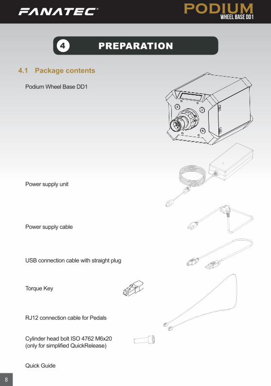
4.1 Package contents
4
Podium Wheel Base DD1
Power supply cable
Power supply unit
USB connection cable with straight plug
Torque Key
RJ12 connection cable for Pedals
Cylinder head bolt ISO 4762 M6x20(only for simplified QuickRelease)
Quick Guide
9
ASSEMBLY
5.1 Plan your configurationTo operate the Podium Wheel Base DD1 plug your steering wheel onto the Quick Release of the Podium Wheel Base DD1 and get started. Connect the Podium Wheel Base DD1 to your PC by using the USB cable.
Please check the ‘Connections’ chapter to see which kind of peripheral devices must be connected to which socket on the Podium Wheel Base DD1. All devic-es have to be connected to the Podium Wheel Base DD1 before powering ON to allow proper detection and operation.
5.2 Mounting the Podium Wheel Base DD1 using the ClubSport Table Clamp V2While it is recommended to hard-mount the Podium Wheel Base DD1 to a ded-icated cockpit, it is possible to use on a strong flat surface using the Fanatec ClubSport Table Clamp V2. Just bolt the Podium Wheel Base DD1 to the Table Clamp with four bolts on the underside of the base.
• You need to take apart the angled plate by loosening the Allen bolt to remove the rod.
• Then you can bolt the plate on the Podium Racing Wheel Base but be careful! Pay attention to the length regulation on page 10!
• Now insert the rod and tighten it with the Allen bolts.
• Open the two metal bolts as much as you need to place on the table.
• Tighten the two metal table clamp bolts. Ensure that the table clamp’s feet remain well aligned with the bottom of the table plate.
5
10
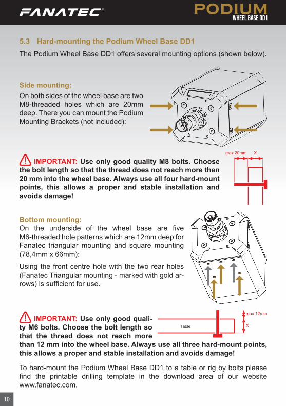
5.3 Hard-mounting the Podium Wheel Base DD1The Podium Wheel Base DD1 offers several mounting options (shown below).
IMPORTANT: Use only good quali-ty M6 bolts. Choose the bolt length so that the thread does not reach more than 12 mm into the wheel base. Always use all three hard-mount points, this allows a proper and stable installation and avoids damage!
IMPORTANT: Use only good quality M8 bolts. Choose the bolt length so that the thread does not reach more than 20 mm into the wheel base. Always use all four hard-mount points, this allows a proper and stable installation and avoids damage!
To hard-mount the Podium Wheel Base DD1 to a table or rig by bolts please find the printable drilling template in the download area of our website www.fanatec.com.
Table
max 12mm
X
max 20mm
X
Side mounting:On both sides of the wheel base are two M8-threaded holes which are 20mm deep. There you can mount the Podium Mounting Brackets (not included):
Bottom mounting:On the underside of the wheel base are five M6-threaded hole patterns which are 12mm deep for Fanatec triangular mounting and square mounting (78,4mm x 66mm):
Using the front centre hole with the two rear holes (Fanatec Triangular mounting - marked with gold ar-rows) is sufficient for use.
11
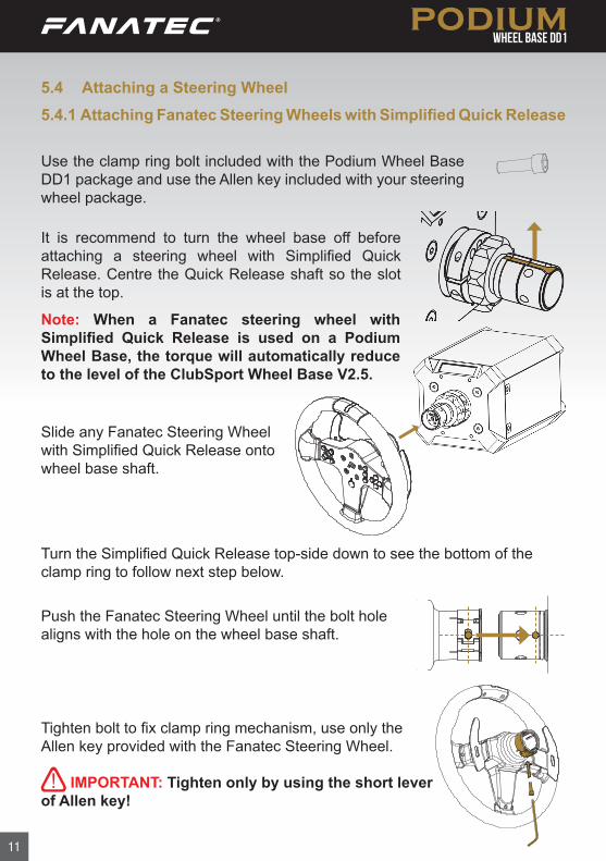
Slide any Fanatec Steering Wheel with Simplified Quick Release onto wheel base shaft.
Turn the Simplified Quick Release top-side down to see the bottom of the clamp ring to follow next step below.
Push the Fanatec Steering Wheel until the bolt hole aligns with the hole on the wheel base shaft.
It is recommend to turn the wheel base off before attaching a steering wheel with Simplified Quick Release. Centre the Quick Release shaft so the slot is at the top.
5.4 Attaching a Steering Wheel 5.4.1 Attaching Fanatec Steering Wheels with Simplified Quick Release
Tighten bolt to fix clamp ring mechanism, use only the Allen key provided with the Fanatec Steering Wheel.
IMPORTANT: Tighten only by using the short lever of Allen key!
Use the clamp ring bolt included with the Podium Wheel Base DD1 package and use the Allen key included with your steering wheel package.
Note: When a Fanatec steering wheel with Simplified Quick Release is used on a Podium Wheel Base, the torque will automatically reduce to the level of the ClubSport Wheel Base V2.5.
12
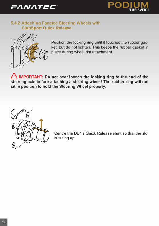
5.4.2 Attaching Fanatec Steering Wheels with ClubSport Quick Release
Position the locking ring until it touches the rubber gas-ket, but do not tighten. This keeps the rubber gasket in place during wheel rim attachment.
Centre the DD1’s Quick Release shaft so that the slot is facing up.
IMPORTANT: Do not over-loosen the locking ring to the end of the steering axle before attaching a steering wheel! The rubber ring will not sit in position to hold the Steering Wheel properly.
13
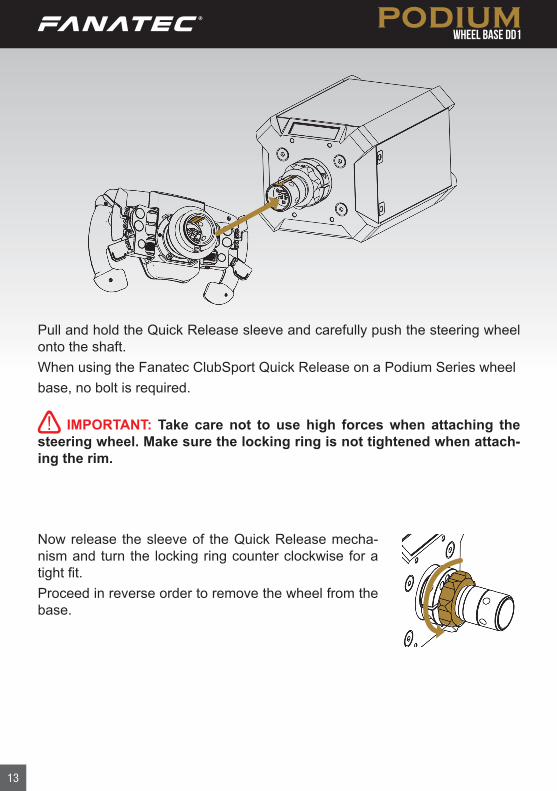
Now release the sleeve of the Quick Release mecha-nism and turn the locking ring counter clockwise for a tight fit.Proceed in reverse order to remove the wheel from the base.
Pull and hold the Quick Release sleeve and carefully push the steering wheel onto the shaft.When using the Fanatec ClubSport Quick Release on a Podium Series wheelbase, no bolt is required.
IMPORTANT: Take care not to use high forces when attaching the steering wheel. Make sure the locking ring is not tightened when attach-ing the rim.
14
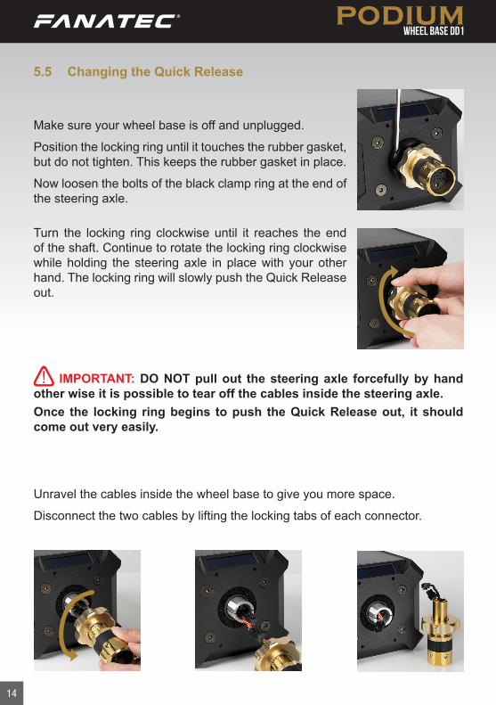
5.5 Changing the Quick Release
Turn the locking ring clockwise until it reaches the end of the shaft. Continue to rotate the locking ring clockwise while holding the steering axle in place with your other hand. The locking ring will slowly push the Quick Release out.
Unravel the cables inside the wheel base to give you more space.
Disconnect the two cables by lifting the locking tabs of each connector.
IMPORTANT: DO NOT pull out the steering axle forcefully by hand other wise it is possible to tear off the cables inside the steering axle.Once the locking ring begins to push the Quick Release out, it should come out very easily.
Make sure your wheel base is off and unplugged.
Position the locking ring until it touches the rubber gasket, but do not tighten. This keeps the rubber gasket in place.
Now loosen the bolts of the black clamp ring at the end of the steering axle.
15
Now connect your new Quick Release system in the same way with the match-ing cables (the short QR cable connects to the long wheel base cable, and the long QR cable connects to the short wheel base cable).
Twist the cable by turning the Quick Release five times to avoid damaging the cables inside the wheel base.
NOTE: The wheel base shaft has a step where the inner diameter decreas-es. It’s important that the connectors clear this step to avoid damaging the cables during reassembly. If necessary, you can try to push the con-nectors carefully with a flat tool to pass the step.Turn the locking ring counter-clockwise until it touches the rubber gasket before you insert the new steering axle.
Push the new steering axle carefully into the wheel base until you feel resist-ance from the step in the shaft.
Put on the clamp ring and tighten the bolts evenly.
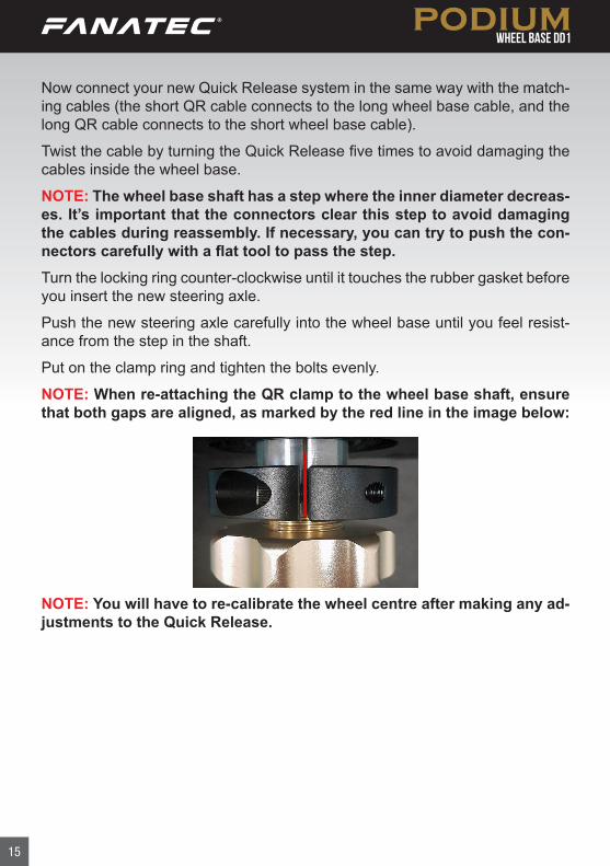
NOTE: When re-attaching the QR clamp to the wheel base shaft, ensure that both gaps are aligned, as marked by the red line in the image below:
NOTE: You will have to re-calibrate the wheel centre after making any ad-justments to the Quick Release.
16
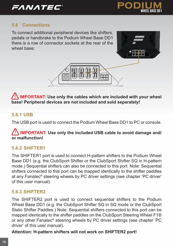
IMPORTANT: Use only the cables which are included with your wheel base! Peripheral devices are not included and sold separately!
5.6 ConnectionsTo connect additional peripheral devices like shifters, pedals or handbrake to the Podium Wheel Base DD1 there is a row of connector sockets at the rear of the wheel base:
5.6.1 USBThe USB port is used to connect the Podium Wheel Base DD1 to PC or console.
IMPORTANT: Use only the included USB cable to avoid damage and/or malfunction!
5.6.2 SHIFTER1The SHIFTER1 port is used to connect H-pattern shifters to the Podium Wheel Base DD1 (e.g. the ClubSport Shifter or the ClubSport Shifter SQ in H-pattern mode.) Sequential shifters can also be connected to this port. Note: Sequential shifters connected to this port can be mapped identically to the shifter paddles at any Fanatec® steering wheels by PC driver settings (see chapter ‘PC driver’ of this user manual).
5.6.3 SHIFTER2The SHIFTER2 port is used to connect sequential shifters to the Podium Wheel Base DD1 (e.g. the ClubSport Shifter SQ in SQ mode or the ClubSport Static Shifter Paddles.) Note: Sequential shifters connected to this port can be mapped identically to the shifter paddles on the ClubSport Steering Wheel F1® or any other Fanatec® steering wheels by PC driver settings (see chapter ‘PC driver’ of this user manual).Attention: H-pattern shifters will not work on SHIFTER2 port!
17
5.6.4 PEDALThe PEDAL port is used to connect pedals to the Podium Wheel Base DD1 (e.g. the ClubSport V3 and Clubsport V3 inverted).
5.6.5 HANDBRAKEThe HANDBRAKE port is used to connect the ClubSport Handbrake V1.5 to the Podium Wheel Base DD1.
5.6.6 POWERThe POWER connector is used to connect the power supply to the Podium Wheel Base DD1.
5.6.7 DATAThe DATA port is to be used for future accessories such as LED displays.
5.6.8 E-STOPThe E-STOP port is for use with the optional Podium Kill Switch.
5.6.9 TORQUE KEYThe TORQUE KEY port is for use with the included Torque Key.
5.6.10 CANThe CAN port is to be used for future CAN bus support.
IMPORTANT: Please use only the power supply and power cord that came with your Podium Wheel Base DD1. Replacements may only be issued from an authorised repair centre. See ‘Electrical Safety’ in Chapter 1 ‘General’ for more details!
18
The Podium Wheel Base DD1 supports a variety of different CSL and ClubSport series steering wheels and other peripheral devices like shifters, pedals and handbrakes. You can obtain these add-on products from the Fanatec webshop: www.fanatec.com
Here are some examples:• ClubSport Steering Wheel Porsche 918 RSR• ClubSport Steering Wheel Formula V2• ClubSport Steering Wheel F1® Esports• ClubSport Steering Wheel BMW GT2• CSL Elite Pedals• CSL Elite Pedals LC• ClubSport Pedals V3• ClubSport Pedals V3 Inverted• ClubSport Shifter SQ V1.5• ClubSport Static Shifter Paddles
Note: IF your ClubSport Static Shifter Paddles do not fit over your clamp ring, you will need to briefly remove the clamp. Please see instructions regarding how to remove the clamp. Removing the full QR is NOT necessary.
IMPORTANT: When mounting the clamp again, the gaps from the clamp and the base shaft needs to be equal to secure proper fitment. (See image on page 15.)
For detailed information about the assembly of other peripheral devices please read the corresponding user manual and/or Quick Guide.
5.7 Drilling TemplatePlease download and print the drilling template for hard-mounting the Podium Wheel Base DD1 from the download area of our website www.fanatec.com.
19
IMPORTANT: A Windows PC is mandatory to perform firmware up-dates!The Podium Wheel Base DD1 firmware provides the wheel functionality, defines the compatibility and handles the communication between the device to PC or console, as well as to other peripheral devices like shifters and pedals.
6.1 Firmware and driver updateThe firmware and the PC driver can be updated to newer versions from www.fanatec.com.
The Podium Wheel Base DD1 is fully workable out-of-box and compatible with existing peripheral devices [per May 2019]. Nevertheless we recommend to always use the latest firmware as these updates may include bug fixes or introduction of new features and compatibilities.
You also have to use the latest PC driver version in order to use the Podium Wheel Base DD1 on a PC.
Run the downloaded file(s) and follow the instructions shown on the screen. See more detailed description later in this user manual chapter.
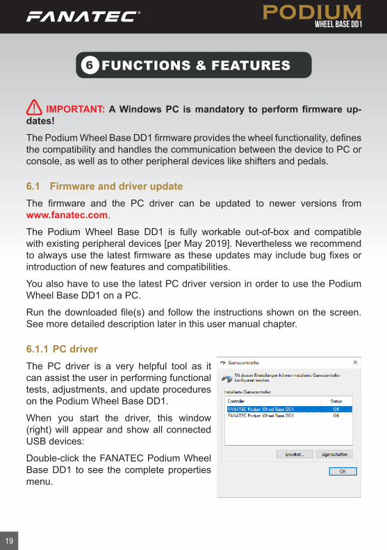
6.1.1 PC driverThe PC driver is a very helpful tool as it can assist the user in performing functional tests, adjustments, and update procedures on the Podium Wheel Base DD1.
When you start the driver, this window (right) will appear and show all connected USB devices:
Double-click the FANATEC Podium Wheel Base DD1 to see the complete properties menu.
FUNCTIONS & FEATURES6
20
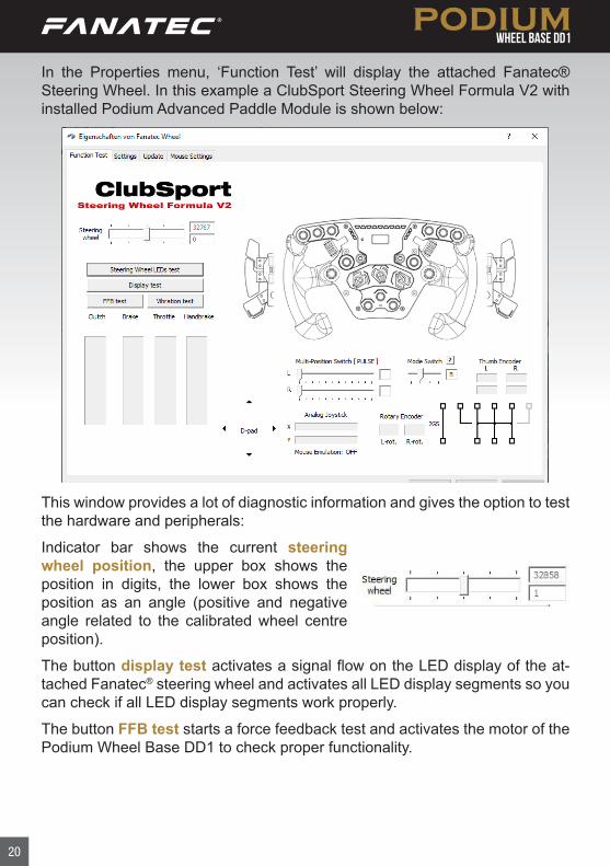
In the Properties menu, ‘Function Test’ will display the attached Fanatec® Steering Wheel. In this example a ClubSport Steering Wheel Formula V2 with installed Podium Advanced Paddle Module is shown below:
This window provides a lot of diagnostic information and gives the option to test the hardware and peripherals:
Indicator bar shows the current steering wheel position, the upper box shows the position in digits, the lower box shows the position as an angle (positive and negative angle related to the calibrated wheel centre position).
The button display test activates a signal flow on the LED display of the at-tached Fanatec® steering wheel and activates all LED display segments so you can check if all LED display segments work properly.
The button FFB test starts a force feedback test and activates the motor of the Podium Wheel Base DD1 to check proper functionality.
21
The button Steering Wheel RevLEDs test starts a signal flow on the LED bar on the steering wheel top side and activates them to test proper functionality of each single LED. This is only available for steering wheels which have Rev-LEDs, refer to the product description of the steering wheel in use.
The button Vibration Test starts a vibration signal to activate the vibration mo-tors inside the Fanatec® steering wheels. This is only available for steering wheels which have vibration motors inside, refer to the product description of the steering wheel in use.
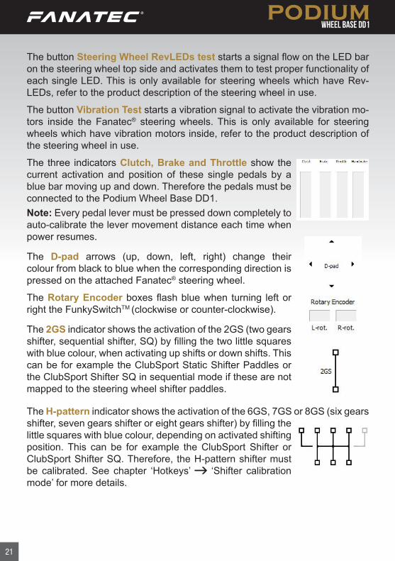
The three indicators Clutch, Brake and Throttle show the current activation and position of these single pedals by a blue bar moving up and down. Therefore the pedals must be connected to the Podium Wheel Base DD1.Note: Every pedal lever must be pressed down completely to auto-calibrate the lever movement distance each time when power resumes.
The D-pad arrows (up, down, left, right) change their colour from black to blue when the corresponding direction is pressed on the attached Fanatec® steering wheel.
The Rotary Encoder boxes flash blue when turning left or right the FunkySwitchTM (clockwise or counter-clockwise).
The 2GS indicator shows the activation of the 2GS (two gears shifter, sequential shifter, SQ) by filling the two little squares with blue colour, when activating up shifts or down shifts. This can be for example the ClubSport Static Shifter Paddles or the ClubSport Shifter SQ in sequential mode if these are not mapped to the steering wheel shifter paddles.
The H-pattern indicator shows the activation of the 6GS, 7GS or 8GS (six gears shifter, seven gears shifter or eight gears shifter) by filling the little squares with blue colour, depending on activated shifting position. This can be for example the ClubSport Shifter or ClubSport Shifter SQ. Therefore, the H-pattern shifter must be calibrated. See chapter ‘Hotkeys’ ‘Shifter calibration mode’ for more details.
22
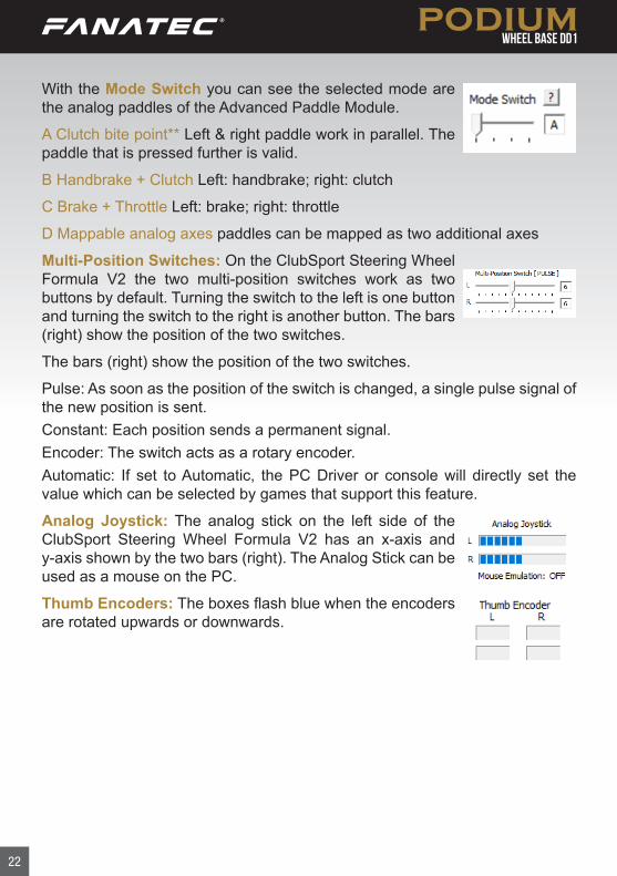
With the Mode Switch you can see the selected mode are the analog paddles of the Advanced Paddle Module.
A Clutch bite point** Left & right paddle work in parallel. The paddle that is pressed further is valid.
B Handbrake + Clutch Left: handbrake; right: clutch
C Brake + Throttle Left: brake; right: throttle
D Mappable analog axes paddles can be mapped as two additional axes
Multi-Position Switches: On the ClubSport Steering Wheel Formula V2 the two multi-position switches work as two buttons by default. Turning the switch to the left is one button and turning the switch to the right is another button. The bars (right) show the position of the two switches.
The bars (right) show the position of the two switches.
Pulse: As soon as the position of the switch is changed, a single pulse signal of the new position is sent.Constant: Each position sends a permanent signal.Encoder: The switch acts as a rotary encoder.Automatic: If set to Automatic, the PC Driver or console will directly set the value which can be selected by games that support this feature.
Analog Joystick: The analog stick on the left side of the ClubSport Steering Wheel Formula V2 has an x-axis and y-axis shown by the two bars (right). The Analog Stick can be used as a mouse on the PC.
Thumb Encoders: The boxes flash blue when the encoders are rotated upwards or downwards.
23
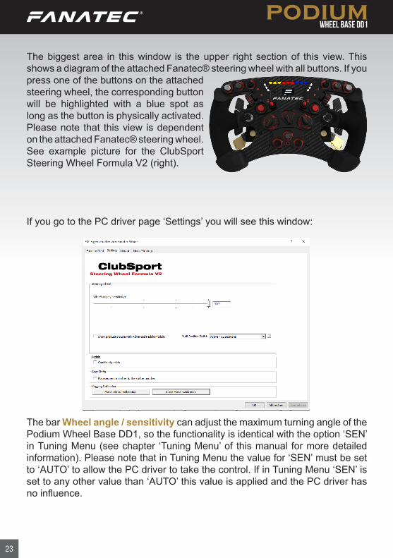
If you go to the PC driver page ‘Settings’ you will see this window:
The bar Wheel angle / sensitivity can adjust the maximum turning angle of the Podium Wheel Base DD1, so the functionality is identical with the option ‘SEN’ in Tuning Menu (see chapter ‘Tuning Menu’ of this manual for more detailed information). Please note that in Tuning Menu the value for ‘SEN’ must be set to ‘AUTO’ to allow the PC driver to take the control. If in Tuning Menu ‘SEN’ is set to any other value than ‘AUTO’ this value is applied and the PC driver has no influence.
The biggest area in this window is the upper right section of this view. This shows a diagram of the attached Fanatec® steering wheel with all buttons. If you press one of the buttons on the attached steering wheel, the corresponding button will be highlighted with a blue spot as long as the button is physically activated. Please note that this view is dependent on the attached Fanatec® steering wheel. See example picture for the ClubSport Steering Wheel Formula V2 (right).
24
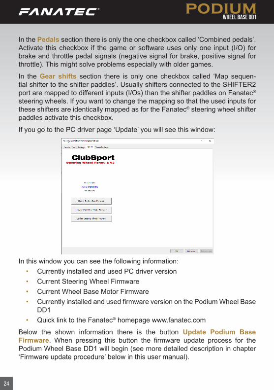
In the Pedals section there is only the one checkbox called ‘Combined pedals’. Activate this checkbox if the game or software uses only one input (I/O) for brake and throttle pedal signals (negative signal for brake, positive signal for throttle). This might solve problems especially with older games.
In the Gear shifts section there is only one checkbox called ‘Map sequen-tial shifter to the shifter paddles’. Usually shifters connected to the SHIFTER2 port are mapped to different inputs (I/Os) than the shifter paddles on Fanatec® steering wheels. If you want to change the mapping so that the used inputs for these shifters are identically mapped as for the Fanatec® steering wheel shifter paddles activate this checkbox.
If you go to the PC driver page ‘Update’ you will see this window:
In this window you can see the following information:• Currently installed and used PC driver version• Current Steering Wheel Firmware• Current Wheel Base Motor Firmware• Currently installed and used firmware version on the Podium Wheel Base
DD1• Quick link to the Fanatec® homepage www.fanatec.com
Below the shown information there is the button Update Podium Base Firmware. When pressing this button the firmware update process for the Podium Wheel Base DD1 will begin (see more detailed description in chapter ‘Firmware update procedure’ below in this user manual).
25
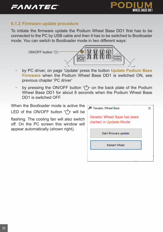
6.1.2 Firmware update procedureTo initiate the firmware update the Podium Wheel Base DD1 first has to be connected to the PC by USB cable and then it has to be switched to Bootloader mode. You can switch to Bootloader mode in two different ways:
• by PC driver, on page ‘Update’ press the button Update Podium Base Firmware when the Podium Wheel Base DD1 is switched ON, see previous chapter ‘PC driver’
• by pressing the ON/OFF button “ ” on the back plate of the Podium Wheel Base DD1 for about 8 seconds when the Podium Wheel Base DD1 is switched OFF.
When the Bootloader mode is active the LED of the ON/OFF button “ ” will be
flashing. The cooling fan will also switch off. On the PC screen this window will appear automatically (shown right).
ON/OFF button “ ”
26
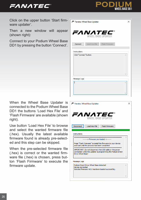
Click on the upper button ‘Start firm-ware updater’.
Then a new window will appear (shown right):
Connect to your Podium Wheel Base DD1 by pressing the button ‘Connect’.
When the Wheel Base Updater is connected to the Podium Wheel Base DD1 the buttons ‘Load Hex File’ and ‘Flash Firmware’ are available (shown right).
Use button ‘Load Hex File’ to browse and select the wanted firmware file (.hex). Usually the latest available firmware found is already pre-select-ed and this step can be skipped.
When the pre-selected firmware file (.hex) is correct or the wanted firm-ware file (.hex) is chosen, press but-ton ‘Flash Firmware’ to execute the firmware update.
27
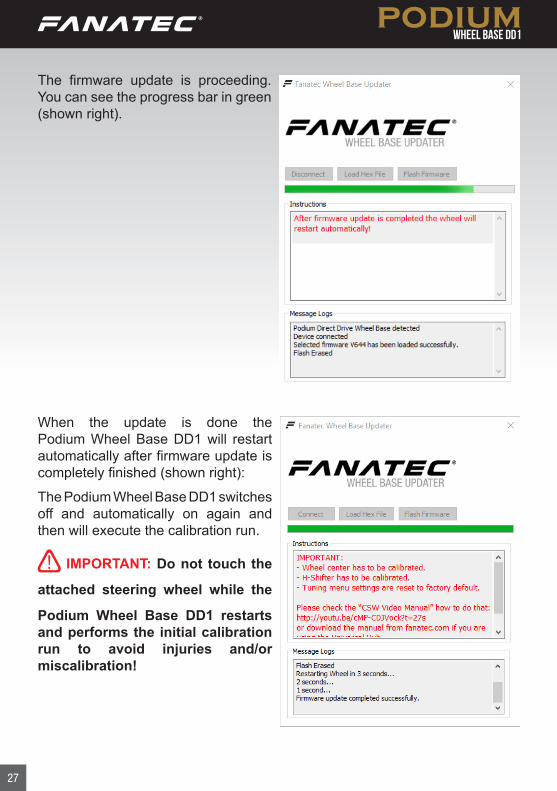
When the update is done the Podium Wheel Base DD1 will restart automatically after firmware update is completely finished (shown right):
The Podium Wheel Base DD1 switches off and automatically on again and then will execute the calibration run.
IMPORTANT: Do not touch the
attached steering wheel while the
Podium Wheel Base DD1 restarts and performs the initial calibration run to avoid injuries and/or miscalibration!
The firmware update is proceeding. You can see the progress bar in green (shown right).
28
IMPORTANT: Software measures protect the product from installation of wrong firmwares on the device. Do not try to force install any firmware.
IMPORTANT: After firmware update the centre position of the Podi-um Wheel Base DD1 has to be manually calibrated again. This is also indicated by the OLED display of the steering wheel showing ‘CAL’. This message will disappear after manual calibration of the wheel centre. See chapter ‘Hotkeys’ ‘Wheel centre calibration’ for more details.
IMPORTANT: After firmware update the H-pattern shifters connected to the Podium Wheel Base DD1 has to be manually calibrated again. See chapter ‘Hotkeys’ ‘Shifter calibration mode’ for more details.
6.2 Start-Up procedure
ATTENTION: When initialisation and auto calibration of the Podium
Wheel Base DD1 is in progress never touch the attached steering wheel in order to avoid injuries or incorrect calibration!
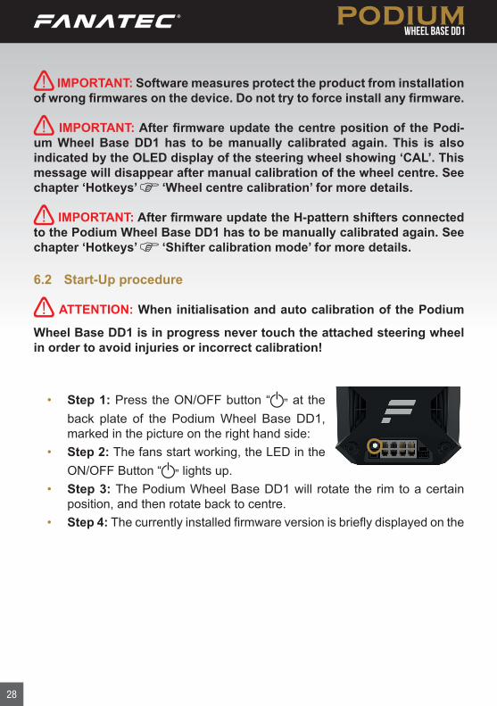
• Step 1: Press the ON/OFF button “ ” at the back plate of the Podium Wheel Base DD1, marked in the picture on the right hand side:
• Step 2: The fans start working, the LED in the ON/OFF Button “ ” lights up.
• Step 3: The Podium Wheel Base DD1 will rotate the rim to a certain position, and then rotate back to centre.
• Step 4: The currently installed firmware version is briefly displayed on the
29
OLED of the Fanatec® steering wheel.• Step 5: If the wheel centre was not yet calibrated ‘CAL’ will blink on the
OLED display of the steering wheel (shown right). ▪ Proceed with a manual wheel centre calibration
as described in chapter ‘Hotkeys’ of this manual.
▪ The Podium Wheel Base DD1 is ready to use after manual wheel centre calibration.
• Step 6: Your Podium Wheel Base DD1 is ready to use. If the wheel centre was previously calibrated, step 5 can be skipped and the Podium Wheel Base DD1 is ready to use immediately. If you use a H-pattern shifter the wheel base firmware will request to calibrate the gears automatically now. Refer to chapter ‘Shifter calibration mode’ later in this user manual.
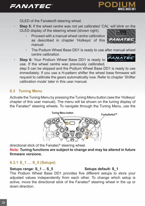
6.3 Tuning MenuActivate the Tuning Menu by pressing the Tuning Menu button (see the ‘Hotkeys’ chapter of this user manual). The menu will be shown on the tuning display of the Fanatec® steering wheels. To navigate through the Tuning Menu, use the
Tuning Menu button FunkySwitchTM
directional stick of the Fanatec® steering wheel.Note: Tuning functions are subject to change and may be altered in future firmware versions.
6.3.1 S_1 … S_5 (Setups)Setups range: S_1 ... S_5 Setups default: S_1The Podium Wheel Base DD1 provides five different setups to store your adjusted values independently from each other. To change which setup is active, move the directional stick of the Fanatec® steering wheel in the up or down direction.
30
There is also an ‘S_0’ setup that is locked to default settings.
6.3.2 SEN (Sensitivity)SEN range: 90 … 1080 AUTO SEN default: AUTOThe sensitivity defines the steering angle. If SEN is set to 90 the steering wheel can only be turned 90° (45° to left and 45° to right side direction from calibrated centre position). If SEN is set to 1080 the steering wheel can be turned the maximum lock of 1080° (540° to left and 540° to right side direction from calibrated centre position). If SEN is set to AUTO the sensitivity is controlled by the PC driver (see chapter PC driver for more details) or games can directly support this feature.
6.3.3 FF (Force Feedback)FF range: OFF 001 … 100 FF default: 35The Force Feedback defines the maximum strength of the motor when force feedback effects from software / games are sent to the Podium Wheel Base DD1. If FF is set to OFF, there will be no force feedback effect executed by the Podium Wheel Base DD1 motor. If FF is set to 001, the motor will execute only 1% of the maximum motor power. If FF is set to 100, the motor will execute 100% of the maximum motor power.
6.3.4 SHO (Shock)SHO range: OFF 010 ... 100 SHO default: 100The strength of the shock / vibration motors inside the Fanatec® steering wheel can be adjusted from 100% to 0%. These vibration motors can be used by a game directly (Fanatec® SDK) or by the ABS function.
6.3.5 ABSABS range: 000 … 100 OFF ABS default: OFFThis feature gives you a direct feedback based on your brake inputs. If you set the value to 100 the vibration will start as soon as you give 100% brake input to the game. If you set it to 95% the vibration will start if you push the brake to 95% or more. The ABS feature uses the vibration within your wheel rim (can be turned off by setting SHO to “0”) AND the vibration motor on a CSP (V2 or V3) pedal set if it is connected directly to the wheel - not individually by USB. ABS can also be simulated dynamically by the game if the developer makes use of
31
the Fanatec® SDK.
6.3.6 Force Effect, Spring Effect, Damper EffectFOR range: OFF 010 … 120 FOR default: 100 (%)SPR range: OFF 010 … 120 SPR default: 100 (%)DPR range: OFF 010 … 120 DPR default: 100 (%)These force feedback modifiers give you the ability to change the force feed-back signals of a game (only applicable if game uses these effects). In theory there are three types of signals which a game can send: Force (pushes the wheel into a specific direction), spring (pulls the wheel towards the dynamic centre) and damper (creates friction). Not every game uses all types of effects and some games even use only one type to create all different feelings. Using your Tuning Menu in the Podium Wheel Base DD1 you can increase or reduce these different effects individually.Note: If SPR is set to low values or ‘OFF’ the Podium Wheel Base DD1 will not be able to move the attached steering wheel to correct centre position after calibration run.
IMPORTANT: Only set these values higher than 100% if the force feed-back effects are clearly not strong enough and weaker in comparison to other games. When the game sends full effects and the wheel is set to 100%, the device will work at its power limit. Pushing up one value to a very high number or even raising multiple values will result in higher load on the motor and increased heat development.For further information check the FAQ section on our websitewww.fanatec.com/support.
6.3.7 Natural DamperNAT DMP range: OFF … 100 NAT DMP default: 050The natural damper will give you an additional damper which you can adjust from OFF to 100. At 100 you will have the strongest dampening effect which reacts to the acceleration and angle of your steering. If you turn it OFF, your steering will have no additional damping, making it easier to turn the wheel. The Natural Damper is a useful setting to reduce unwanted wheel oscillation. Oscillation is typically caused by latency in the feedback loop, and is more apparent in racing games that are not optimised for high-torque motors. The
32
default value of 50 is a good balance between steering responsiveness and oscillation mitigation.
6.3.8 Natural FrictionNFR range: OFF ... 100 NFR default: OffThe natural friction setting is used to simulate the mechanical feel of a vehicle’s steering components. The higher the setting, the more resistance you will feel when rotating the wheel. This can enhance the feeling of driving vehicles with-out power steering, or with very wide tyres. This setting can also help to prevent oscillation.
6.3.9 Force Effect IntensityFEI range: 0 ... 100 FEI default: 100This parameter adjusts the overall intensity of force effects and can make ef-fects smoother: OFF is very smooth while 100 is very sharp and direct. Tuning this parameter can help to refine a harsh or spiky force feedback signal in some games.
6.3.10 MPS (Function of Multi Position Switch)MPS: Auto; Encoder; Constant; Pulse MPS default: AUTOIn AUTO mode the steering wheel decides which mode is appropriate for the game being played. In Encoder mode the MPS simulates two buttons, one when you turn the MPS left and one when you turn the MPS right.In Constant mode, the MPS outputs a constant button signal for each position. In PULSE Mode, the MPS outputs a specific button signal for each position which is only sent as a single pulse when you move the switch.
6.3.11 BRF (brake force)BRF range: OFF 010 … 100 BRF default: 050BRF allows to adjust the brake feeling: Increasing BRF to 100 means the user needs to press the brake with minimum force to achieve 100% brake signal. Reducing BRF to OFF means the user needs to press the brake only with maximum force to achieve 100% brake signal. You can either check the brake signal level on the PC driver or you can see it on the attached steering wheel (depending on steering wheel type). NOTE: BRF is only available when a supported pedal set is connected to
33
wheel base’s PEDAL port. Please read the description and/or manuals of your pedals to verify if the BRF feature is supported.
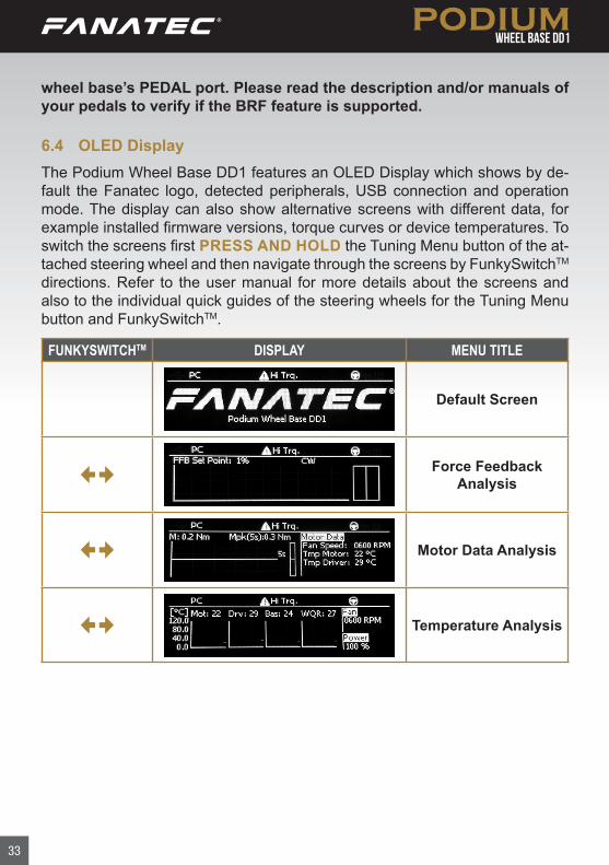
6.4 OLED Display The Podium Wheel Base DD1 features an OLED Display which shows by de-fault the Fanatec logo, detected peripherals, USB connection and operation mode. The display can also show alternative screens with different data, for example installed firmware versions, torque curves or device temperatures. To switch the screens first PRESS AND HOLD the Tuning Menu button of the at-tached steering wheel and then navigate through the screens by FunkySwitchTM directions. Refer to the user manual for more details about the screens and also to the individual quick guides of the steering wheels for the Tuning Menu button and FunkySwitchTM.
FUNKYSWITCHTM DISPLAY MENU TITLE
Default Screen
Force Feedback
Analysis
Motor Data Analysis
Temperature Analysis
34
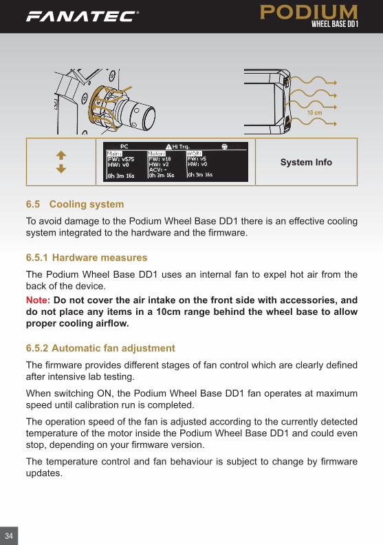
10 cm
System Info
6.5 Cooling systemTo avoid damage to the Podium Wheel Base DD1 there is an effective cooling system integrated to the hardware and the firmware.
6.5.1 Hardware measuresThe Podium Wheel Base DD1 uses an internal fan to expel hot air from the back of the device.Note: Do not cover the air intake on the front side with accessories, and do not place any items in a 10cm range behind the wheel base to allow proper cooling airflow.
6.5.2 Automatic fan adjustmentThe firmware provides different stages of fan control which are clearly defined after intensive lab testing.
When switching ON, the Podium Wheel Base DD1 fan operates at maximum speed until calibration run is completed.
The operation speed of the fan is adjusted according to the currently detected temperature of the motor inside the Podium Wheel Base DD1 and could even stop, depending on your firmware version.
The temperature control and fan behaviour is subject to change by firmware updates.
35
ELECTRICAL OPERATION
7.1 Hotkeys
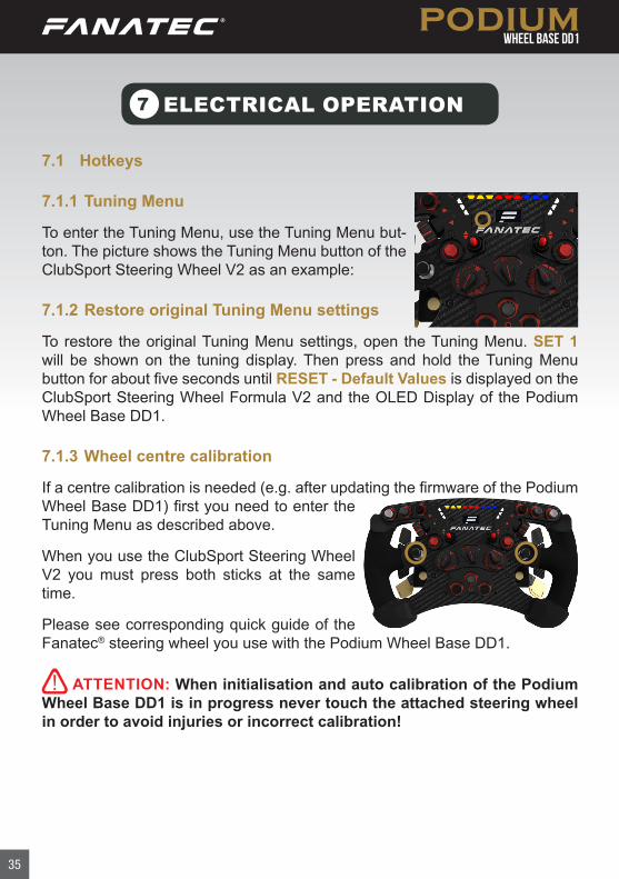
7.1.1 Tuning Menu
To enter the Tuning Menu, use the Tuning Menu but-ton. The picture shows the Tuning Menu button of the ClubSport Steering Wheel V2 as an example:
7.1.2 Restore original Tuning Menu settings
To restore the original Tuning Menu settings, open the Tuning Menu. SET 1 will be shown on the tuning display. Then press and hold the Tuning Menu button for about five seconds until RESET - Default Values is displayed on the ClubSport Steering Wheel Formula V2 and the OLED Display of the Podium Wheel Base DD1.
7.1.3 Wheel centre calibration
If a centre calibration is needed (e.g. after updating the firmware of the Podium Wheel Base DD1) first you need to enter the Tuning Menu as described above.
When you use the ClubSport Steering Wheel V2 you must press both sticks at the same time.
Please see corresponding quick guide of the Fanatec® steering wheel you use with the Podium Wheel Base DD1.
ATTENTION: When initialisation and auto calibration of the Podium Wheel Base DD1 is in progress never touch the attached steering wheel in order to avoid injuries or incorrect calibration!
7
36
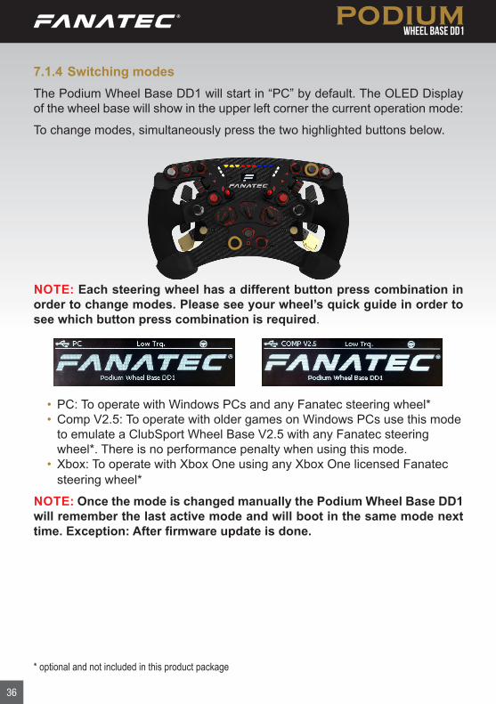
7.1.4 Switching modesThe Podium Wheel Base DD1 will start in “PC” by default. The OLED Display of the wheel base will show in the upper left corner the current operation mode:
To change modes, simultaneously press the two highlighted buttons below.
NOTE: Each steering wheel has a different button press combination in order to change modes. Please see your wheel’s quick guide in order to see which button press combination is required.
* optional and not included in this product package
• PC: To operate with Windows PCs and any Fanatec steering wheel*• Comp V2.5: To operate with older games on Windows PCs use this mode
to emulate a ClubSport Wheel Base V2.5 with any Fanatec steering wheel*. There is no performance penalty when using this mode.
• Xbox: To operate with Xbox One using any Xbox One licensed Fanatec steering wheel*
NOTE: Once the mode is changed manually the Podium Wheel Base DD1 will remember the last active mode and will boot in the same mode next time. Exception: After firmware update is done.
37
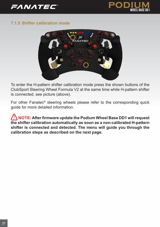
7.1.5 Shifter calibration mode
To enter the H-pattern shifter calibration mode press the shown buttons of the ClubSport Steering Wheel Formula V2 at the same time while H-pattern shifter is connected, see picture (above).
For other Fanatec® steering wheels please refer to the corresponding quick guide for more detailed information.
NOTE: After firmware update the Podium Wheel Base DD1 will request the shifter calibration automatically as soon as a non-calibrated H-pattern shifter is connected and detected. The menu will guide you through the calibration steps as described on the next page.
38
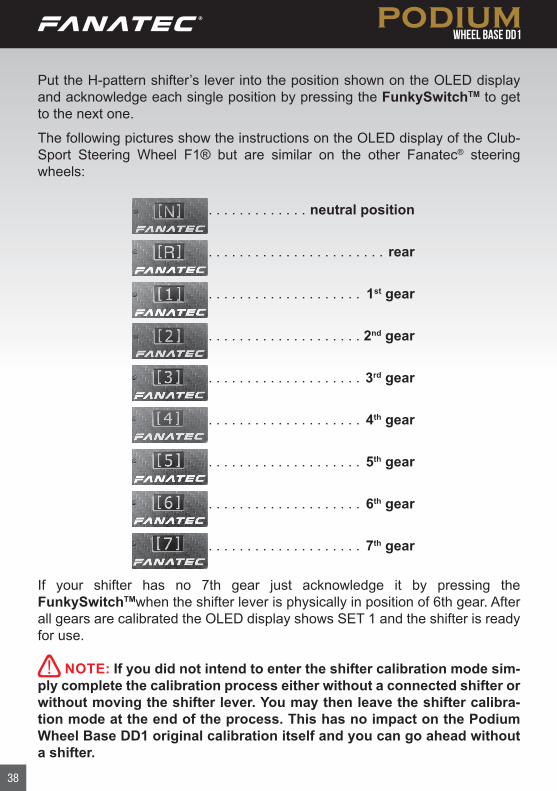
Put the H-pattern shifter’s lever into the position shown on the OLED display and acknowledge each single position by pressing the FunkySwitchTM to get to the next one.
The following pictures show the instructions on the OLED display of the Club-Sport Steering Wheel F1® but are similar on the other Fanatec® steering wheels:
. . . . . . . . . . . . . neutral position
. . . . . . . . . . . . . . . . . . . . . . . rear
. . . . . . . . . . . . . . . . . . . . 1st gear
. . . . . . . . . . . . . . . . . . . . 2nd gear
. . . . . . . . . . . . . . . . . . . . 3rd gear
. . . . . . . . . . . . . . . . . . . . 4th gear
. . . . . . . . . . . . . . . . . . . . 5th gear
. . . . . . . . . . . . . . . . . . . . 6th gear
. . . . . . . . . . . . . . . . . . . . 7th gear
If your shifter has no 7th gear just acknowledge it by pressing the FunkySwitchTMwhen the shifter lever is physically in position of 6th gear. After all gears are calibrated the OLED display shows SET 1 and the shifter is ready for use.
NOTE: If you did not intend to enter the shifter calibration mode sim-ply complete the calibration process either without a connected shifter or without moving the shifter lever. You may then leave the shifter calibra-tion mode at the end of the process. This has no impact on the Podium Wheel Base DD1 original calibration itself and you can go ahead without a shifter.
39
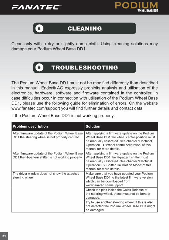
TROUBLESHOOTING9
The Podium Wheel Base DD1 must not be modified differently than described in this manual. Endor® AG expressly prohibits analysis and utilisation of the electronics, hardware, software and firmware contained in the controller. In case difficulties occur in connection with utilisation of the Podium Wheel Base DD1, please use the following guide for elimination of errors. On the website www.fanatec.com/support you will find further details and contact data.
If the Podium Wheel Base DD1 is not working properly:
Problem description Solution
After firmware update of the Podium Wheel Base DD1 the steering wheel is not properly centred.
After applying a firmware update on the Podium Wheel Base DD1 the wheel centre position must be manually calibrated. See chapter ‘Electrical Operation ‘Wheel centre calibration’ of this manual for more details.
After firmware update of the Podium Wheel Base DD1 the H-pattern shifter is not working properly.
After applying a firmware update on the Podium Wheel Base DD1 the H-pattern shifter must be manually calibrated. See chapter ‘Electrical Operation’ ‘Shifter Calibration Mode’ of this manual for more details.
The driver window does not show the attached steering wheel.
Make sure that you have updated your Podium Wheel Base DD1 to the latest firmware version which can be downloaded from www.fanatec.com/support.Check the pins inside the Quick Release of the steering wheel, these must not be bent or damaged.Try to use another steering wheel. If this is also not detected the Podium Wheel Base DD1 might be damaged.
Clean only with a dry or slightly damp cloth. Using cleaning solutions may damage your Podium Wheel Base DD1.
CLEANING8
40
Problem description Solution
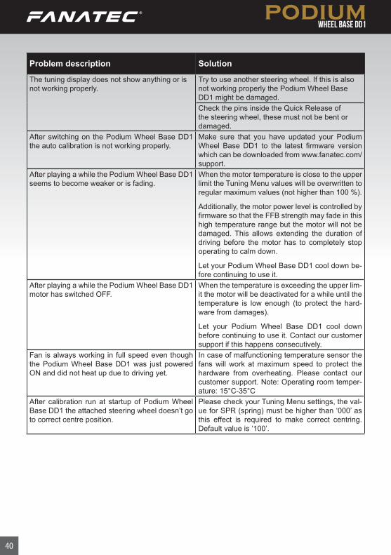
The tuning display does not show anything or is not working properly.
Try to use another steering wheel. If this is also not working properly the Podium Wheel Base DD1 might be damaged.Check the pins inside the Quick Release of the steering wheel, these must not be bent or damaged.
After switching on the Podium Wheel Base DD1 the auto calibration is not working properly.
Make sure that you have updated your Podium Wheel Base DD1 to the latest firmware version which can be downloaded from www.fanatec.com/support.
After playing a while the Podium Wheel Base DD1 seems to become weaker or is fading.
When the motor temperature is close to the upper limit the Tuning Menu values will be overwritten to regular maximum values (not higher than 100 %).
Additionally, the motor power level is controlled by firmware so that the FFB strength may fade in this high temperature range but the motor will not be damaged. This allows extending the duration of driving before the motor has to completely stop operating to calm down.
Let your Podium Wheel Base DD1 cool down be-fore continuing to use it.
After playing a while the Podium Wheel Base DD1 motor has switched OFF.
When the temperature is exceeding the upper lim- it the motor will be deactivated for a while until the temperature is low enough (to protect the hard- ware from damages).
Let your Podium Wheel Base DD1 cool down before continuing to use it. Contact our customer support if this happens consecutively.
Fan is always working in full speed even though the Podium Wheel Base DD1 was just powered ON and did not heat up due to driving yet.
In case of malfunctioning temperature sensor the fans will work at maximum speed to protect the hardware from overheating. Please contact our customer support. Note: Operating room temper-ature: 15°C-35°C
After calibration run at startup of Podium Wheel Base DD1 the attached steering wheel doesn’t go to correct centre position.
Please check your Tuning Menu settings, the val-ue for SPR (spring) must be higher than ‘000’ as this effect is required to make correct centring. Default value is ‘100’.
41
TRADEMARKS
SERIAL NUMBER
11
10
“Fanatec®” and “Endor®” are registered trademarks of Endor® AG/Germany. All rights reserved.
All other trademarks are the property of their respective owners.
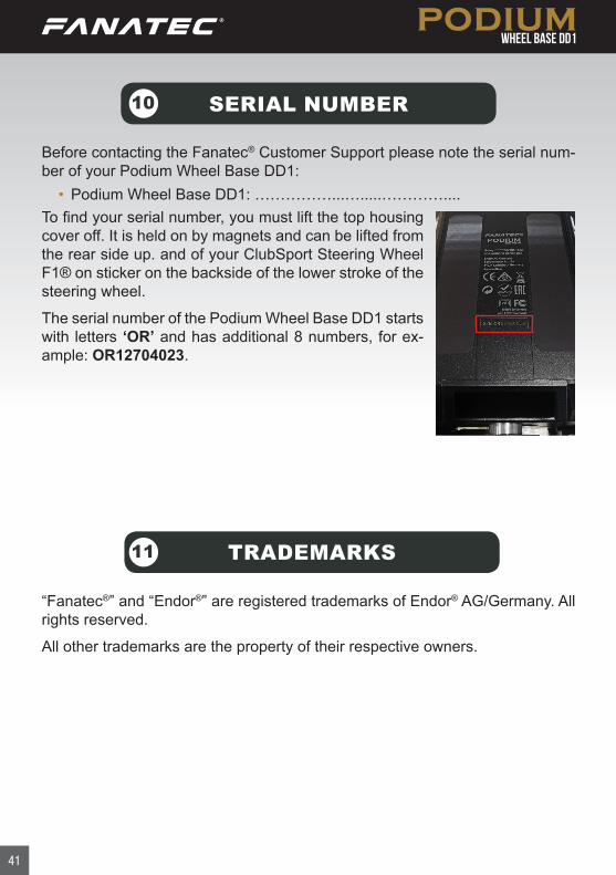
Before contacting the Fanatec® Customer Support please note the serial num-ber of your Podium Wheel Base DD1:
• Podium Wheel Base DD1: ……………...….....…………....To find your serial number, you must lift the top housing cover off. It is held on by magnets and can be lifted from the rear side up. and of your ClubSport Steering Wheel F1® on sticker on the backside of the lower stroke of the steering wheel.
The serial number of the Podium Wheel Base DD1 starts with letters ‘OR’ and has additional 8 numbers, for ex-ample: OR12704023.

42
END OF LIFE PRODUCT RECYCLING
12
Please follow your local regulations when disposing of this product as e-waste.
FCC COMPLIANCE13
This device complies with part 15 of the FCC rules. The operation of this device is subject to the following two conditions:
• This device may not cause harmful interference, and must accept any interference received, including interference that may cause undesired operation.
• This device was not modified different than described explicitly in this user manual.
Note: This device was tested and approved to the limitations for class B of digital devices according to part 15 of the FCC rules. This limitations should en-sure an adequate protection against harming interferences in residental areas. However, a warranty for not-occuring of interferences is not assumed.
Do not modify the device different than described explicitly in this user manual. Nevertheless, if you do modifications different from the described in this manual you can be determined to stop the operation of the device.
43
WARRANTY14
Endor® AG („Endor“) warrants to the original purchaser that the Fanatec® prod-uct, which includes components contained in the retail box with this product will be free from material defects in material and workmanship for a period of one year from the original date of purchase (the “Warranty Period”). This warranty is valid in the country where the product was purchased. If this product is de-termined to be materially defective during the warranty period, your sole remedy and Endor’s sole and exclusive liability is limited to the repair or replacement of this product with a factory-recertified product, at Endor’s option. For purposes of this Limited Hardware Warranty and Liability, “factory recertified” means a product that has been returned to its original specifications.
This warranty does not apply if this producta) is used with products that are not expressly declared in the product
descriptions as compatible with this product;b) is used with peripherals Endor does not license, expressly approve
or sell. This includes non-licensed hardware enhancement devices, controllers, adaptors, and power supply devices (“non-licensed/non-approved peripherals”);
c) is used for any commercial purpose, including rental or arcade purposes;
d) is modified or tampered with contrary to the operating and maintenance instructions;
e) is damaged by the acts of God (natural disasters), negligence, accidents, wear and tear, unreasonable use, or by causes unrelated to defective materials or workmanship;
f) has the serial number altered, defaced or removed (where applicable);g) has the warranty seal altered, defaced or removed (where applicable).
This warranty does not cover consumables (such as batteries) or prod-ucts sold and clearly marked „AS IS“ or with faults. Endor may void this warranty if1) Endor reasonably believes that the product has been used in a manner
that violates the terms of a separate end user agreement for firmware, system software or game software;
44
2) the product is used with non-licensed/non-approved peripherals. Consumer assume all risks and liabilities associated with use of third-party products.
This warranty is provided to you in lieu of all other express or implied warranties. This includes warranties of merchantability and fitness for a particular purpose for this product, which Endor disclaims under these terms. However, if applicable law requires any of these warranties, then they are limited in duration to the warranty period.
Except as expressly stated above, Endor excludes all liability for loss of data, loss of profit, or any loss or damage suffered by you or any third party, whether those damages are direct, indirect, consequential, special, or incidental and however arising under any theory of law, as a result of using this product. Some states or provinces do not allow limitations on how long an implied warranty lasts and some states do not allow the exclusion or limitations of consequential or incidental damages, so these limitations or exclusions may not apply to you. This warranty gives you specific legal rights. You may also have other rights which vary from state to state or province to province. The warranty offered by Endor on this product is the same whether or not you register your product.
This warranty does not apply to any system software / firmware that is prein-stalled in the purchased product, or is subsequently provided via update or up-grade releases. In case of issues apparently related to system software / firm-ware as well as any other product related issues, Endor recommends checking the FAQ database at www.fanatec.com/support to see if your problem can be solved there.

Made in China
Fanatec® is a registered trademark of Endor AG Designed and developed by Endor AG in Germany
Manufactured by
The F1 FORMULA 1 logo, F1 logo, FORMULA 1, FORMULA ONE, F1, FIA FORMULA ONE WORLD CHAMPIONSHIP, GRAND PRIX and related marks are trade marks of Formula One Licensing BV, a Formula 1 company. Licensed by Formula One World Championship Limited, a Formula 1 company. All rights reserved.
Seligenthaler Straße 16 a - 84034 Landshut - GermanyTelephone: +49 (871) 9221-122 Fax: +49 (871) 9221-221Email: [email protected]: www.fanatec.com - www.endor.ag
04/2019


![Killing with keyboards[opsec]](https://static.documents.pub/doc/80x56/54c4192f4a79593a3b8b456e/killing-with-keyboardsopsec.jpg)

