U s e r M a n u a l S t a nd - a l o n e P r o g r a m m a b l e L i m i t S w i t c h e s ADV ANCED MICRO CONTROLS INC. iPLC intelligent Programmable Limit Controller iPLC-1 iPLC-2 iPLC-4 Manual #: 940-0L011
Transcript
User M
anual
Stand-alone Programm
able L
imit
Sw
itc
hes
ADV ANC EDMIC RO CON T RO L S INC.
iPLC intelligent Programmable Limit Controller
iPLC-1iPLC-2iPLC-4
Manual #: 940-0L011
GENERAL INFORMATION
Important User Information
The products and application data described in this manual are useful in a wide variety of different applica-tions. Therefore, the user and others responsible for applying these products described herein are responsible for determining the acceptability for each application. While efforts have been made to provide accurate infor-mation within this manual, AMCI assumes no responsibility for the application or the completeness of the information contained herein.UNDER NO CIRCUMSTANCES WILL ADVANCED MICRO CONTROLS, INC. BE RESPONSIBLE OR LIABLE FOR ANY DAMAGES OR LOSSES, INCLUDING INDIRECT OR CONSEQUENTIAL DAM-AGES OR LOSSES, ARISING FROM THE USE OF ANY INFORMATION CONTAINED WITHIN THIS MANUAL, OR THE USE OF ANY PRODUCTS OR SERVICES REFERENCED HEREIN.No patent liability is assumed by AMCI, with respect to use of information, circuits, equipment, or software described in this manual.The information contained within this manual is subject to change without notice.This manual is copyright 2010 by Advanced Micro Controls Inc. You may reproduce this manual, in whole or in part, for your personnal use, provided that this copyright notice is included. You may distribute copies of this complete manual in electronic format provided that they are unaltered from the version posted by Advanced Micro Controls Inc. on our official website: www.amci.com. You may incorporate portions of this documents in other literature for your own personal use provided that you include the notice “Portions of this document copyright 2010 by Advanced Micro Controls Inc.” You may not alter the contents of this document or charge a fee for reproducing or distributing it.
Standard WarrantyADVANCED MICRO CONTROLS, INC. warrants that all equipment manufactured by it will be free from defects, under normal use, in materials and workmanship for a period of [18] months. Within this warranty period, AMCI shall, at its option, repair or replace, free of charge, any equipment covered by this warranty which is returned, shipping charges prepaid, within eighteen months from date of invoice, and which upon examination proves to be defective in material or workmanship and not caused by accident, misuse, neglect, alteration, improper installation or improper testing.The provisions of the "STANDARD WARRANTY" are the sole obligations of AMCI and excludes all other warranties expressed or implied. In no event shall AMCI be liable for incidental or consequential damages or for delay in performance of this warranty.
Returns PolicyAll equipment being returned to AMCI for repair or replacement, regardless of warranty status, must have a Return Merchandise Authorization number issued by AMCI. Call (860) 585-1254 with the model number and serial number (if applicable) along with a description of the problem. A "RMA" number will be issued. Equipment must be shipped to AMCI with transportation charges prepaid. Title and risk of loss or damage remains with the customer until shipment is received by AMCI.
24 Hour Technical Support Number24 Hour technical support is available on this product. If you have internet access, start at www.amci.com. Product documentation and FAQ’s are available on the site that answer most common questions.
If you require additional technical support, call (860) 583-7271. Your call will be answered by the factory dur-ing regular business hours, Monday through Friday, 8AM - 5PM Eastern. During non-business hours an auto-mated system will ask you to enter the telephone number you can be reached at. Please remember to include your area code. The system will page an engineer on call. Please have your product model number and a description of the problem ready before you call.
We Want Your FeedbackManuals at AMCI are constantly evolving entities. Your questions and comments on this manual are both wel-comed and necessary if this manual is to be improved. Please direct all comments to: Technical Documenta-tion, AMCI, 20 Gear Drive, Terryville CT 06786, or fax us at (860) 584-1973. You can also e-mail your questions and comments to [email protected]
ADVANCED MICRO CONTROLS INC.
TABLE OF CONTENTS
General InformationImportant User Information ..................... IFCStandard Warranty ................................... IFCReturns Policy .......................................... IFC24 Hour Technical Support Number ........ IFC
About This ManualIntroduction .............................................. 3Navigating this Manual ............................ 3Revision Record ....................................... 3
CHP 1: IntroductionOverview .................................................. 5iPLC System Functions ........................... 5iPLC System Operation ........................... 6Typical iPLC System Applications .......... 6Series iPLC Family Members .................. 6iPLC Part Numbering System .................. 7Compatible Transducers .......................... 8
Single-Turn Transducers ............... 8Multi-Turn Transducers ................. 9Using Transducers from
Connecting Power .................................... 26iPLC Power Wiring ...................... 26MRB-1 Power Wiring ................... 27IM-(x) Power Wiring .................... 28
Programming ............................... 43Programming Repeat Setpoints ..... 44Using a Limit Output as a
Transducer Fault Output ............. 44
Additional Programming Instructions ...... 45Other Instructions for iPLC-2 Systems ......................................... 45Other Instructions for iPLC-4 Systems ......................................... 46
CHP 5: Clearing Error MessagesOverview .................................................. 47Clearing a Transducer Fault ..................... 47Clearing an EEPROM Error ..................... 48Clearing a Program ................................... 48Clearing a RAM Error .............................. 48Displaying Model Number &
Checksum Data ....................................... 49
ADVANCED MICRO CONTROLS INC.2
ABOUT THIS MANUAL
IntroductionThis manual explains the operation, installation, and programming of each Intelligent Programmable Limit Controller (iPLC) System manufactured by Advanced Micro Controls Inc. (AMCI). The Series iPLC Sys-tems include the iPLC-1, iPLC-2, and iPLC-4.
The AMCI logo is a trademark and “AMCI” is a registered trademark of Advanced Micro Controls Inc. Viton is a registered trademark of E.I. DuPont.”Adobe” and “acrobat” are registered trademarks of Adobe Systems Incorporated. All other trademarks contained herein are the property of their respective holders.
Navigating this ManualThe layout of this manual allows it to be used in both printed and on-line formats. Its on-line form is a PDF document, which requires Adobe Acrobat Reader version 6.0 or a similar reader before you can open it.
Bookmarks of all the chapter names, section headings, and sub-headings were created in the PDF file so that you can easily find what you are looking for. The bookmarks should appear when you open the file. If they don’t, press the F5 key on Windows platforms to bring them up.
Throughout this manual you will also find green text that functions as a hyperlink in HTML documents. Clicking on the text will immediately jump you to the referenced section of the manual. If you are reading a printed manual, most links have the page numbers included.
The PDF file is password protected to prevent changes to the document. You are allowed to select and copy sections for use in other documents.
Manual ConventionsThree icons are used to highlight important information in the manual:
NOTES highlight important concepts, decisions you must make, or the implications of those decisions.
CAUTIONS tell you when equipment may be damaged if the procedure is not followed properly.
WARNINGS tell you when people may be hurt or equipment may be damaged if the proce-dure is not followed properly.
Revision RecordThe following is the revision history for this manual. In addition to the information listed here, revisions will fix any known typographical errors and clarifications may be added.
This manual, 940-0L011, modifies page 22 of the 940-0L010 manual to show the dimensions and pinout of the new IM-(x) modules.
Revision History940-0L011: Changed IM drawing on page 22 to reflect new IM-(x) dimensions
940-0L010: Complete rewrite of the manual
iPLC-493M: Original cataloged manual
It is strongly recommended that you read the following instructions. If there are any unanswered questions after read-ing this manual, check out our website at www.amci.com for additional information on our iPLC Systems as well as therest of AMCI’s products. If you still need answers to specific questions, call the factory. An applications engineer will beavailable to assist you.
OverviewSeries iPLC Systems are designed to accurately synchronize machine functions to the absolute posi-tion of a rotating shaft. Each system provides a number of Programmable Limit Switch (PLS) out-puts, which may be used to control machine func-tions with mechanical or solid state relays in a stand-alone system or in conjunction with Program-mable Limit Controllers (PLCs) or industrial com-puters. Additional standard features include a Motion Detector (MD) output, inhibit input, and tachometer. A wide variety of software and hard-ware options are also available.
The minimum configuration for each iPLC System includes: 1) a controller unit which includes an operator display/keypad for monitoring the system, and programming PLS and MD output; 2) a relay board or interface module for transferring input/output signals; and 3) a single-turn brushless, resolver-based trans-ducer for position feedback.
System expansion capabilities allow you to add up to four transducers and multiple relay boards to provide up to 64 PLS outputs, with multiple limit setpoints programmable for each output channel. Each system can include one, two, or four transducers to support one-axis, two-axis or four-axis, single turn limit applications. 100 Turn and 180 Turn Absolute Software options are also available to support multi-turn absolute limit applications.
iPLC System FunctionsEach iPLC System allows you to:
Monitor the transducer position or velocity, and change the values of the controller’s programmable parameters using the operator display and keypad.
Enter transducer setup parameters including a scale factor, circular offset, and auto-zero position.
Run or define a maximum of four programs with specific limit setpoints for each output channel.
Enter a program code for each program to restrict access to the program’s commands.
Define multiple limit setpoints and repeat setpoints for each output channel.
Inspect limit setpoints defined for each output channel in a specific program.
Program the Motion Detector output to turn off or on depending on the speed of the transducer.
Monitor and clear error messages that appear on the operator display.
Figure 1.1 iPLC Controller Unit
SF OFFSET MD LO +PROGRAM
ENTERLS REPEAT T/C A B CLEAR -
0 2 3 4
5 6 7 8 9NEXT
POS/TACFUNCTION
1
. Park, Terryville, CT 0678660) 584-1973 http://www.amci.com
5
INTRODUCTION1
iPLC System Operation
The transducer in each iPLC System is coupled to the shaft of the controlled machine, supplying analog sig-nals proportional to the shaft position. The microcomputer-based electronics in the controller unit convert these analog signals to digital format using a ratiometric A to D converter. The controller then compares this digital shaft position data to the limit setpoints programmed in the controller’s non-volatile EEPROM mem-ory. When the transducer shaft reaches these setpoints, the PLS outputs are turned ON or OFF, starting or stopping the desired machine functions. Maximum scan time is 200 µsec per transducer channel, from input to output. The number of limit setpoints programmed for output channels in use do not affect the system scan time.
Typical iPLC System ApplicationsAn iPLC System application generally falls into one of two general categories:
Rotary Application - The resolver position directly correlates to an angular position on the machine. One example is monitoring a press ram. As the press cycles through one turn, the resolver position is used to monitor and control such functions as material feed and part blow-off.
Linear Application - The resolver position correlates to a physical length. These applications can be either single turn or multi-turn. An example of a single turn application is a packaging machine where the resolver completes one turn for each product. Here the resolver position is used to control when glue is applied or when the package is cut to length. An example of a multi-turn application is monitoring the position of a load on either a track or ball screw such as an overhead crane. In this type of application, linear position is translated to rotary position through either a wheel or gearing. The transducer com-pletes several rotations to travel the complete distance.
Series iPLC Family MembersThe systems available in the iPLC series are listed below. Complete operation, installation, programming, and servicing instructions for each of the basic systems are provided in this manual. For instructions describing how to use the iPLC Options (e.g., Options M and N listed below), refer to the separate iPLC Options manual.
Table 1.1 Series iPLC Family Members
† The letter in each of these model numbers indicates that the identified system includes a specific option.
Model Transducer Inputs
Max. Full Scale Turns
Max. Full Scale Count
Max. # of Outputs Comments
iPLC-1 1 1 1000 64 Single turn, 3 digit PLS
iPLC-2 2 1 each 1000 32 2 channel, single turn, 3 digit PLS
iPLC-4 4 1 each 1000 32 4 channel, single turn, 3 digit PLS
ADVANCED MICRO CONTROLS INC.6
INTRODUCTION 1
iPLC Part Numbering System
1 - One resolver input
2 - Two resolver input
4 - Four resolver input
iPLC-X-XX OPTIONS - Leave blank if none.
OUTPUTS†
1 - 16 Open Collector Sinking Outputs, 120 Vac Line
2 - 16 Open Collector Sinking Outputs, 240 Vac Line
3 - 32 Open Collector Sinking Outputs, 120 Vac Line
4 - 32 Open Collector Sinking Outputs, 240 Vac Line
5 - 64 Open Collector Sinking Outputs,‡ 120 Vac Line
6 - 64 Open Collector Sinking Outputs,‡ 240 Vac Line
7 - 16 Open Emitter Sourcing Outputs, 120 Vac Line
8 - 16 Open Emitter Sourcing Outputs, 240 Vac Line
9 - 32 Open Emitter Sourcing Outputs, 120 Vac Line
10 - 32 Open Emitter Sourcing Outputs, 240 Vac Line
13 - 16 +5Vdc TTL Compatible Outputs, 120 Vac Line
14 - 16 +5Vdc TTL Compatible Outputs, 240 Vac Line
†Outputs refer to the number of Limit Switch outputs. All iPLC Controllers also have a Motion Detector out-put assigned to the first resolver. This output is always Open Collector Sinking.
Single-Turn TransducersThe AMCI single-turn transducers compatible with iPLC Systems are listed in the following table.
† Available gear ratios are: 2:1, 2.5:1, 2.77:1, 3:1, 4:1, 4.8:1, 5:1, 6:1, 7:1, 8:1, 9:1, 10:1, 12:1, 13:1, 15:1, 16:1, 18:1, 20:1, 24:1, 36:1, 40:1, 50:1, 60:1, 64:1, 100:1, 105:1, 150:1,180:1, 250:1 and 256:1. Additional gear ratios may be available. Check our website, www.amci.com, for an up-to-date listing.
‡ This package contain two resolvers geared 1:1 with the input shaft. Most commonly used in systems that mandate redundant sensors. AMCI can install two different size 11 resolvers in the package per customer requirements. Contact AMCI for more information.
Table 1.2 Compatible AMCI Single-Turn Transducers
Model Shaft Mount Turns Comments
R11X-J10/7 0.120" Servo 1 NEMA 1, size 11 resolver
R11X-J12/7 0.188" Servo 1 NEMA 1, size 11 resolver
HT-6 0.188" Front/Side 1 NEMA 13 R11X-J12/7 transducer
HT-20 0.625" Front/Side 1 NEMA 4 heavy duty transducer
HT-20S 0.625" Front/Side 1 HT-20 with side connector
HT-20C 0.625" Front/Side 1 NEMA 4X stainless steel HT-20 w/ Viton® shaft seal, and conduit connector
HT-20K 0.625" Front/Side 1 NEMA 4X hard coat anodized HT-20, stainless steel shaft w/ Viton shaft seal.
HT-20KS 0.625" Front/Side 1 HT-20K with side connector.
HT-20L 0.625" Front/Side 1 NEMA 4X hard coat anodized HT-20, stainless steel shaft w/ Nitrile shaft seal.
HT-20LS 0.625" Front/Side 1 HT-20L with side connector.
H25-FE 0.375" Flange 1 NEMA 4, size 25, end connector
H25-F1E 0.375" Flange 1 NEMA 4, size 25, end connector. Bolt-in replace-ment for Namco/C&A HT-11B transducers.
H25-FS 0.375" Flange 1 NEMA 4, size 25, side connector
H25-FL 0.375" Flange 1 NEMA 4, size 25, integral 15 foot (5 meter) cable
H25-SE 0.375" Servo/Front 1 NEMA 4, size 25, end connector
H25-SS 0.375" Servo/Front 1 NEMA 4, size 25, side connector
H25-SL 0.375" Servo/Front 1 NEMA 4, size 25, integral 15 foot (5 meter) cable
HT-400 0.625" Front 1 NEMA 4, Bolt-in replacement for Autotech RL100 transducers.
HT-20-(x) 0.625" Front (x)† HT-20 with internal (x):1 gear ratio
HTT-20-1 0.625" Front 1‡ Redundant single turn resolvers.
HTT-400-1 0.625" Front 1‡ Redundant single turn resolvers. Bolt-in replace-ment for Autotech RL220 transducers.
ADVANCED MICRO CONTROLS INC.8
INTRODUCTION 1
Compatible Transducers (continued)
Multi-Turn TransducersThe AMCI multi-turn transducers compatible with iPLC Systems are listed in the following table.
†A 1,000 turn version is also available. Table 1.3 Compatible AMCI Multi-Turn Transducers
In the above table, note that Option M is required for 100/1,000 turn transducers and Option N is required for 180/1,800 turn transducers.
Each multi-turn transducer contains two resolvers. The first resolver, called the fine resolver, is attached directly to the input shaft through a flexible coupler. The second resolver, the course resolver, is geared to the fine. This gear ratio, either 99:100 or 179:180 determines the total number of turns the transducer can encode.
At the mechanical zero of the transducer, the electrical zeros of the two resolvers are aligned. See Figure 1.2A. After one complete rotation, the zero of the course resolver lags behind the zero of the fine by one tooth, either 1/100 or 1/180 of a turn. After two rotations the lag is 2/100 or 2/180. See Figures 1.2B and 1.2C. After 100 or 180 turns, the electrical zeros of the resolvers are realigned and the multi-turn cycle begins again.
The fine resolver yields the absolute position within the turn directly. Using a proprietary algorithm, the iPLC-2 System with either Option M or N can determine the number of turns completed by calculating the difference in positions of the two resolvers. The absolute multi-turn position is then calculated as ((number of turns completed * counts per turn) + fine resolver position).
The 1,000 and 1,800 turn transducers have a 10:1 gear ratio between the input shaft and the resolvers. There-fore, they can encode ten times the number of turns but at a tenth of the resolution.
Model Shaft Mount Turns Comments
HTT-20-100 0.625" Front 100 NEMA 4 heavy duty transducer
HTT-20-180 0.625" Front 180 NEMA 4 heavy duty transducer
HTT-20-1000 0.625" Front 1,000 HTT-20-100 w/additional 10:1 gearing on input shaft.
HTT-20-1800 0.625" Front 1,800 HTT-20-180 w/additional 10:1 gearing on input shaft.
HT425-Ann-100† 0.250" Motor 100 A-B Series 1326 motor mount transducer. “nn” in part number defines connector style.
HT425-Mnn-100† 10 mm Motor 100 Universal motor mount w/required adapter plate. “nn” in part number defines connector style.
HT425-Fnn-100† 0.625" Front 100 NEMA 4X, HTT-20-100 w/ Viton shaft seal. “nn” in part number defines connector style.
HT425-Tnn-100† 0.625" Foot 100 NEMA 4X, HTT-20-100 w/ Viton shaft seal. “nn” in part number defines connector style.
HTT-400-100 0.625" Front 180 NEMA 4, HTT-20-180. Bolt-in replacement for Autotech RL220 transducers.
Figure 1.2 Resolver Alignment in Multi-Turn Transducers
COARSE COARSECOARSEFINE FINEFINE
0 0 0 0 0 0
A B CMechcanical Zero After One Turn After Two Turns
Using Transducers from Other ManufacturersTransducers from Autotech, Namco/C&A, and other manufacturers may be used with iPLC Systems if you purchase an AMCI Reference Module. For more information, download the FAQ: Using Transducers from Other Manufacturers from our website, www.amci.com.
Programmable ParametersYou may configure an iPLC System by setting the values of its Programmable Parameters. These parameters may be broken down into two groups:
Transducer Setup Parameters - Include three parameters that affect the position and tachometer data. These parameters are programmable from the controller keyboard.
Limit Switch Parameters - Basically include ON/OFF limit setpoints for the output PLS channels and ON/OFF parameters for the Motion Detector output. All of these parameters are also programmable from the controller keyboard.
Programmable Parameters are stored in each controller’s nonvolatile memory. Therefore, you do not have to configure a controller after every power up. The nonvolatile memory is nvRAM. This type of memory chip provides an unlimited number of write cycles and will retain its values in the absence of power for approxi-mately ten years.
Transducer Setup Parameters
Scale FactorThe Scale Factor sets the number of counts per turn of the transducer (i.e., the number of angular divisions within one revolution of the transducer shaft). You may enter a Scale Factor of from 2 to 1,000 depending on the application.
The Scale Factor default value is 1,000.
Note that when the Scale Factor is set to 360, the Position value is defined in angular degrees. The Scale Fac-tor also controls the resolution of the ON and OFF points of the Limit Outputs. When the Scale Factor is set to 360, the Limit Outputs can turn ON and OFF every one angular degree. Programming the Scale Factor resets the Circular Offset to zero.
The remainder of this chapter introduces the various types of parameters that you may use toconfigure an iPLC System, the different types of iPLC Software and Hardware Options that maybe purchased, and the available output interfaces.
ADVANCED MICRO CONTROLS INC.10
INTRODUCTION 1
Transducer Setup Parameters (continued)
Circular OffsetThe Circular Offset parameter indicates the angular displacement of the transducer shaft from electrical (true) zero. This parameter allows you to adjust the position reported by an iPLC System without rotating the shaft (i.e., the Circular Offset value is a positive displacement added to the angular position read from the trans-ducer). Use the following formulas to calculate the Circular Offset if the offset presently equals zero.
If Desired Position > Current Position:Circular Offset = Desired Position - Current PositionExample 1: Scale Factor = 360
Current Position = 134, Desired Position = 200Circular Offset = 200 - 134 = 66
If Desired Position < Current Position:Circular Offset = Scale Factor - (Current Position - Desired Position) Example 2: Scale Factor = 360
Current Position = 238, Desired Position = 123Circular Offset = 360 - (238 - 123) = 360 - (115) = 245
If the Circular Offset is not zero when calculating a new offset, then it must be taken into account. Calculate your new Circular Offset as shown in the previous examples and then add the current Circular Offset value to your answer. If this new offset is greater than or equal to the value of the Scale Factor, then subtract the Scale Factor from the new offset.
To continue Example 2, Calculated Circular Offset = 245Present Circular Offset = 306Circular Offset = 245 + 306 = 551
(Note that this offset value exceeds the Scale Factor of 360.)New Circular Offset = 551 - 360 = 191
AutoZero FeatureThe AutoZero feature quickly calculates the Circular Offset needed to bring the position value to zero. For more details describing how to use this feature, see Using the Auto-Zero Feature found on page 39.
Limit Switch Parameters
ON/OFF Limit SetpointsMultiple ON/OFF limit setpoints may be entered for each output channel or circuit. Each ON setpoint for a specific output represents the Machine Position (i.e., the transducer position reported by the iPLC Controller Unit) where you want the output to turn ON. The corresponding OFF setpoint represents the Machine Posi-tion where you want the output to turn OFF. ON and OFF setpoints are always programmed in pairs. An out-put is ON when the Machine Position is greater than or equal to the ON setpoint and less than the OFF setpoint specified in a pair.
For example, an ON setpoint of 230 and an OFF setpoint of 270 will turn the selected output ON each time the Machine Position reaches 230 and OFF when the Machine Position reaches 270.
ON/OFF Motion Detector SetpointsYou may also enter limit setpoints to turn the Motion Detector (MD) output ON or OFF if the speed of the transducer (recorded in RPM as a tachometer speed) is either between or outside two setpoints. For example, you could program the MD output to turn ON if the transducer speed falls below 10 RPM or exceeds 50 RPM. See Programming Motion Detector Setpoints found on page 40 for more information.
The following standard options are available with normal delivery times. Refer to the separate iPLC System Options manual for detailed information about Options A, D, J1, K, M, N, O, V1 and V2.
Automatic Advance - Option AAllows you to advance or offset the PLS outputs as a function of speed to compensate for the fixed delays of components in variable speed machines. For example, if a limit output controls a solenoid that pulls mechani-cally 50 milliseconds after voltage is applied to its terminals and the machine’s motor is running at 25 RPM, the automatic advance would compensate for a potential error of 7.5 degrees. This option can only be used on output channels 1 through 8. Only one delay (or a sum of several delays) may be compensated for on each channel.
Stop Time Monitor - Option BLThis option may be used to monitor the brake stopping time. It is available for iPLC Systems with either 32 or 64 outputs. Contact AMCI for more information.
Remote Display - Option DProvides an RS422A serial output that supplies position and tachometer data to the Series D6000 Remote Display from AMCI or other intelligent devices. This option is available for iPLC Systems with either 16 or 32 outputs, and can not be used for systems that have Option Q and/or S.
0.1 RPM Tachometer - Option JThis option provides an 0.1 RPM tachometer for measuring the transducer velocity (i.e., the speed of the rotating shaft measured by the transducer). Contact AMCI for more information.
Dwell Timer - Option J1Allows you to measure the transducer shaft’s time of travel between two programmed positions. The start and end of the time interval are programmed as ON and OFF limit setpoints on output channel #16.
Program Lockout - Option KProvides an input to lockout or disable the Program Mode on an iPLC Controller Unit. For example, the input may be connected to a switch key to prevent unauthorized personnel from programming the unit. The input could also be connected to a “RUNNING” output from the controlled machine, to prevent the operator from accidentally programming incorrect parameters into the iPLC System.
100 Turn Absolute Software - Option MEnables an iPLC Controller Unit to function as a multi-turn absolute limit switch. That is, the controller will always read the correct position when it is powered up even if the transducer shaft was rotated when the con-troller was shut down. The programmable number of turns is 1, 2, 4, 5, 10, 20, 25, 50 and 100. Either the 100 or the 1,000 turn transducers from AMCI must be used with this option.
180 Turn Absolute Software - Option NAlso enables an iPLC Controller Unit to function as a multi-turn absolute limit switch. The programmable number of turns is 1, 2, 3, 4, 5, 6, 9, 10, 12, 15, 18, 20, 30, 36, 45, 60, 90 and 180. Either the 180 or the 1,800 turn transducers from AMCI must be used with this option.
ADVANCED MICRO CONTROLS INC.12
INTRODUCTION 1
iPLC Software/Hardware Options (continued)
iPLC-2 Remote Reset/Preset - Option OThis option may be used with an iPLC-2 System to allow the operator to preset the position of each transducer included in the system to a programmable value when there is a positive (0 to1) transition on a remote input. Two inputs are available to allow the operator to preset each transducer separately.
Additional Programs - Option PGProvides four additional programs to bring the total number of programs available with an iPLC System to eight. Inputs are available on the controller unit to allow the operator to select any of the eight programs to run from a remote location.
RS422 Serial Communications - Option QSupplies an RS422 serial output that provides serial communications for programming and data inspection. This option is available for iPLC Systems with either 16 or 32 outputs, and can not be used in systems that have Option D and/or S.
iPLC-1 Registration Control & Batch Counter - Option RThis option may be used with an iPLC-1 System to provide synchronization between a registration mark imprinted on the processed material and rotating parts of the controlled machine. Typical applications include cutting, stamping, printing, punching, etc.
RS232C Serial Communications - Option SSupplies an RS232C serial output that provides serial communications for programming and data inspection. This option is available for iPLC Systems with either 16 or 32 outputs, and can not be used in systems that have Option D and/or Q.
iPLC-1 Quasi-Absolute Multi-Turn Software - Option UThis option may be used with an iPLC-1 System to enable the controller unit to function as a multi-turn abso-lute limit switch. The maximum number of turns is 999. The maximum number of Full Scale counts is 131,072 and the Maximum Counts Per Turn is 1,024. This system remains absolute if the transducer is not allowed to make more than a one half turn rotation while power is removed from the controller.
iPLC-1 Analog Output, 0-10 Vdc - Option V1This option may be used with an iPLC-1 System to continuously output an analog voltage proportional to the position displayed on the controller unit. The output voltage may be used for many different applications including remote displays and remote position sensing.
iPLC-1 Analog Output, 4-20 mA - Option V2This option may be used with an iPLC-1 System to continuously output an analog current proportional to the position displayed on the controller unit. This signal may be used for many different applications including remote displays and remote position sensing.
AMCI offers both relay boards and an “interface module” for connecting the iPLC inputs and outputs to the rest of your system. Relay boards are used when a voltage and/or power level translation is required. The AMCI IM-(x) interface module simply brings the iPLC I/O out to screw terminals for field wiring.
IM-(x) Interface Module This DIN rail mountable I/O block offers all forty pins available from the iPLC. No isolation is provided with the IM-(x). Typically, the IM-(x) is used to wire the iPLC to a programmable controller where isolation is pro-vided by the PLC input card. The (x) in the IM-(x) part number is the length in feet of the ribbon cable that attaches the IM to the iPLC Controller Unit. For example, the IM-1 has a one foot ribbon cable.
RB-1 Solid State Relay BoardThe RB-1 is the standard AMCI solid state relay board that uses Opto 22 AC and DC relays. Offering 16 limit switch outputs and one motion detector output, the board also has an Inhibit Input that can be used to disable all the outputs. This input is commonly tied to the Motion Detector output so that the outputs do not fire unless the machine is running at its proper speed. All the outputs are normally open.
RB-2 Solid State Relay BoardThis relay board is designed for use with the iPLC-1 System with the BL option. The RB-2 is identical to the RB-1 except for output 16. This output position is reconfigured to use a solid state AC input relay tied to the presses’ brake clutch.
MRB-1 Mechanical Relay BoardThis relay board uses Omron SPDT relays. Offering 16 limit switch outputs and one Motion Detector output, the board also has an Inhibit Input that can be used to disable all the outputs. This input is commonly tied to the Motion Detector output so that the outputs do not fire unless the machine is running at its proper speed. Both the normally open and normally closed contacts are available. This relay board requires an external 12 Vdc @ 1A supply to operate.
Relay Board OptionsAll of the relay boards can be ordered with optional connectors. Table 1.4 shows the available connector options. Note that any of the connector options can be combined except for W and Z. The following table also lists other iPLC options that require a specific connector option for correct wiring.
Table 1.4 iPLC Relay Board Connector Options
Two relay boards are required if an iPLC has thirty-two outputs and one of the relay boards must be ordered with the “X” option. The first relay board can be plugged directly into the iPLC Controller Unit, and the sec-ond relay board must be plugged into the first board. The relay board with the “X” option provides outputs 1-16 and the second relay board provides outputs 17-32. If you order an iPLC-1 System with sixty-four outputs, you will need four relay boards, two of which must have the “X” option.
Option Comments iPLC Options
X J5 Expansion Connector iPLC-1-3/4/5/6, iPLC-2-3/4, iPLC-4-3/4
Y Adds Input and Communications Terminal Blocks. D, K, M, N, O, PG, Q, R, S, U, V1, V2
W Plug-in terminal blocks Not needed by any option, only changes wiring style of outputs.
Z Changes from Top to Front wire entry terminal blocks.
Not needed by any option, only changes wiring style of outputs.
ADVANCED MICRO CONTROLS INC.14
INTRODUCTION 1
Available Relays
Table 1.5 lists specifications for the solid-state and mechanical relays available from AMCI.
Table 1.5 AMCI Solid-State and Mechanical Relays
KA-1 KA-2 KD-1 KD-2 KM-1
Type AC Solid State AC Solid State DC Solid State DC Solid State AC/DC Mechanical
Manufacturer Opto 22MP120D4
Opto 22MP240D4
Opto 22DC60MP
Opto 22DC200MP
OmronG2R-1-S
Voltage Range 12 - 140Vac 24 - 280Vac 4 - 60 Vdc 4 - 200Vdc 250Vac / 30Vdc
Peak Repetitive Voltage 500Vac 500Vac – – 380Vac / 125Vdc
Nominal Current 3Arms 3Arms 3Adc 1Adc 10Aac/dc resistive7.5Aac/5Adc inductive
Surge Current 85Apk / 1 Cycle
85Apk / 1 Cycle 5Adc / 1 sec. 2Adc / 1 sec. 10 Aac/dc
General GuidelinesWhen wiring any control system, these guidelines must be followed to prevent electromagnetic interference:
WiringResolver cable should be treated as low-level signal and communication cable. Route resolver cables in wireways or conduits that contain osimilar cables such as low-power digital ac/dc I/0 lines, communica-tions cables, or low voltage analog I/O lines.Like all signal and communication cable, the resolver cable must be shielded. The shield must be grounded at one end only, typically at the input to the controller. If a junction must be made in the signal cable, treat the shield as a signal-carrying conductor. Do not connect the shield to ground at any junction box or the transducer. If the signal cable must cross power feed lines, it should do so at right angles.Route at least five feet from high voltage enclosures, or sources of “rf” radiation.
GroundingAll ground connections must be permanent and continuous to provide a low-impedance path to earth ground for induced noise currents. The unit’s chassis must be connected to chassis ground through the use of mounting hardware, or a grounding wire connected to the metal case of the unit. Scrape away any paint around the mounting holes to ensure a good connection. Any device that interfaces to the unit must be connected to the same chassis ground to avoid ground loops. All isolation transformer secondary windings must be grounded to the same earth ground as the machine ground.
Surge SuppressionSurge suppression devices should be placed across the coil of an inductive device to reduce the effects of high voltage transients (i.e., varistors, diodes, etc.).
MountingIf the mounting bracket is coated with a non-conductive material, scrape the material around the mount-ing hole and use a star washer to ensure good contact with the mounting surface. When mounting a controller on an enclosure door, do not rely on the hinge to make a good electrical connection between the door and the enclosure. A bonding wire from the door to the rest of the enclo-sure must be installed.
This chapter describes how to install each basic component in a Series iPLC System, includingthe controller unit, relay board or interface module, and transducer. It also provides informationdescribing how to connect power and output/input wiring.
. Park, Terryville, CT 0678660) 584-1973 http://www.amci.com
17
INSTALLATION2
Available Enclosures
When you purchase an iPLC System with an enclosure, AMCI will mount all the appropriate components in the enclosure. You are only required to mount the enclosure and perform the appropriate wiring to complete the installation. The correct enclosure for each iPLC System is listed in the following table:
Table 2.1 iPLC System Enclosures
Enclosure DimensionsThe location of the mounting holes for the EN Enclosures is illustrated in Figure 2.1. This figure and the fol-lowing table also provide the dimensions of each enclosure available from AMCI. Note that there are one 1/2” and one 1/4” conduit holes drilled in the left side of the enclosure for wiring the system.
Figure 2.1 EN Enclosures Outline Drawing
iPLC Outputs Enclosure
iPLC-1 16 Relay Outputs (1 relay board) EN-1W
iPLC-1 32 Relay Outputs (2 relay boards) EN-2W
iPLC-1 IM-1 Interface Module EN-1W/IM
iPLC-2 16 or 32 Relay Outputs (1 or 2 relay boards) EN-2-1W
iPLC-4 16 or 32 Relay Outputs (1 or 2 relay boards) EN-2-1W
iPLC-2 or iPLC-4 IM-1 Interface Module EN-2-1W/IM
A B C
EN-1W 10.00" (254) 10.75" (273) 11.50" (292)
EN-2W 16.00" (406) 16.75" (425) 17.50" (445)
ADVANCED MICRO CONTROLS INC.18
INSTALLATION 2
Mounting the iPLC Controller
Remove system power before removing or installing the controller unit. Failure to observe this warning may result in damage to the controller’s circuitry and/or undes-ired operation with possible injury to personnel.
All of the iPLC Controller Units have both front and rear mount brackets. Each type of bracket allows you to mount the controller unit using four screws inserted at the corners of the bracket. Refer to Figure 2.2 for the location of the mounting holes in the front and rear mount brackets, and the dimension of the controller. If you intend to use the front mounting holes, remove the rear mount brackets before installation as shown below.
*The J3 connector is in this position for iPLC-1 Controller Units. On iPLC-2 units, the J3 connector is on the top of the unit. For iPLC-4 units, J3 is a 14-pin connector located on the top of each unit.
**On iPLC-1 Controller Units with 64 outputs, an additional J1 connector is provided on the top of each unit.
Remove system power before removing or installing a relay board. Failure to observe this warning may result in damage to the circuitry on the controller or relay board, and/or undesired operation with possible injury to personnel.
When planning your installation, mount the relay boards as close as possible to the iPLC con-troller unit. The relay boards are connected to the controller unit using ribbon cables. (AMCI part number CR-(x), where (x) is the length in feet.) Long ribbon cables make the signals sus-ceptible to noise. If your ribbon cable is longer than two feet, AMCI strongly suggests using shielded ribbon cable. (AMCI part number CRS-(x) where (x) is the length in feet.)
This section describes how to install both the relay boards commonly purchased with an iPLC System, including the RB-1 and the MRB-1 Relay Board.
RB-1 BoardThis relay board has a total of five threaded standoffs provided for mounting, including four at the corners of the board and one standoff near the center as illustrated in Figure 2.3 below. This figure also provides the dimensions of the board. The RB-1 board can be easily mounted in the bottom interior of a Model EN-1 or EN-2 Enclosure (see Figure 2.1 for the dimensions of this enclosure).
Figure 2.3 RB-1 Relay Board Outline Drawing
ADVANCED MICRO CONTROLS INC.20
INSTALLATION 2
MRB-1 Board
This relay board also has a total of five threaded standoffs provided for mounting, including four at the cor-ners of the board and one standoff near the center as illustrated in Figure 2.4. This figure also provides the dimensions of the board. The MRB-1 board can be easily mounted in the bottom interior of a Model EN-1 or EN-2 Enclosure (see Figure 2.1 for the dimensions of this enclosure).
Remove system power beforeremoving or installing the interface module. Failure to observe thsi warning may result in damage to the controller’s circuitry and/or undesired operation with possible injury to personnel.
When planning your installation, mount the interface module as close as possible to the iPLCcontroller unit. The interface module is connected to the controller unit using ribbon cables. (AMCI part number CR-(x), where (x) is the length in feet.) Long ribbon cables make the signals susceptible to noise. If your ribbon cable is longer than two feet, AMCI strongly suggests using shielded ribbon cable. (AMCI part number CRS-(x) where (x) is the length in feet.)
You can easily install the IM-(X) Interface Module using the plastic tabs on the bottom of the module shown in Figure 2.5 below. The module can be mounted on following DIN Rails
EN 05 022 - 35 x 7.5 (35 x 7.5 mm) EN 05 022 - 35 x 15 (35 x 15 mm)
Figure 2.5 also provides the dimensions of the module, which has a connector for the ribbon cable from an iPLC Controller and a 40-pin output terminal block for transferring output signals from the controller to a PLC or computer.
The appropriate outline drawing is included with each transducer shipped from AMCI. You may also view outline drawings and detailed specifications for all the transducers compatible with iPLC Systems on the AMCI web site at “www.amci.com”.
Digital and Chassis grounds are connected together inside the iPLC Controller Unit. Therefore, proper grounding techniques must be followed when installing the unit. Improperly grounding the system may result in ground loops or ground fault currents that will damage the unit. Systems that use relay boards rarely encounter this problem because the relay boards isolate the outputs. Systems that use IM modules may experi-ence this problem when the power supply connected to the IM is also used to power other parts of the system. If the power supply and its loads are not properly grounded, the iPLC Controller Unit may be used as the path to ground for currents that are large enough to damage the unit.
iPLC Power WiringDepending on the type of controller unit, insert a 120 or 240 Vac power cord into the IEC powerline connector on the left side of the unit as illustrated in Figure 2.10. The fuse that protects the controller’s circuitry from excess line voltage may also be accessed on this side of the unit as shown below.
Figure 2.10 iPLC Controller Unit Powerline Connection
1) The iPLC Controller Unit is grounded through the ground wire of its power cord (i.e., the green wire). This wire must be attached to the system’s ground bus. The NEMA enclosure that houses the controller unit must also be bonded to the ground bus.
2) When mounting the controller unit, you must also have a good electrical connection between the controller and the panel you are mounting the unit on. Remove paint and other non-conductive finishes from around the mounting studs or tapped holes and use star lock washers so that a solid electrical connection is made at each mounting point.
3) If you are mounting the iPLC Controller Unit on an enclosure door, do not rely on the hinge to make a good electrical connection between the door and the rest of the enclosure. A bonding wire from the door to the rest of the enclosure must be installed.
ADVANCED MICRO CONTROLS INC.26
INSTALLATION 2
Connecting Power (continued)
MRB-1 Power WiringMRB-1 relay boards require an external 12 Vdc supply for operation. Each relay requires about 60 mA to operate, for a total current draw per board of one amp if the board is fully populated with seventeen relays. The power terminals for an MRB-1 relay board are located in the bottom left corner of the board as shown below.
Figure 2.11 MRB-1 Relay Board Power Connections
The negative side of the power supply is tied to earth ground through its connection to the digital ground of the iPLC Controller Unit. (The negative side of the supply and the unit’s digital ground must be tied together or the relays will not fire. The controller unit internally ties its digital ground to chassis.) You may encounter one of two problems if you use a system-wide power supply to drive the MRB-1. Because of these problems, AMCI suggest using a dedicated 12Vdc 1A supply to drive only the MRB-1.
1) You may affect the iPLC Controller Unit’s operation by injecting noise into the unit from other devices that use a system power supply. In severe cases, where large induc-tive loads are switched by the system power supply, you may even damage the output drivers of the controller unit.
2) There is a possibility that these other system devices could use the controller unit as their path to earth ground. This problem results from incorrect grounding and could damage the unit.
IM-(x) Power WiringThe method that you should use to wire power to the IM module depends on the type of outputs (sinking, sourcing, or TTL) in the iPLC Controller Unit. However, the caution below applies regardless of the type of outputs in the controller unit.
The negative side of the power supply is tied to earth ground through its connection to the digital ground of the iPLC Controller Unit. (The negative side of the supply and the unit’s digital ground must be tied together or the relays will not fire. The controller unit internally ties its digital ground to chassis.) You may encounter one of two problems if you use a system-wide power supply to drive the IM-(x). Because of these problems, AMCI suggest using a dedicated supply to drive only the IM-(x).
1) You may affect the controller unit’s operation by injecting noise into the unit from other devices that use a system power supply. In severe cases, where large inductive loads are switched by the system power supply, inductive spikes that exceed the maxi-mum voltage spec of the output drivers will eventually damage them.
2) There is a possibility that these other system devices could use the controller unit as their path to earth ground. This problem results from incorrect grounding and could damage the controller.
Sinking Outputs Attach the negative side of the supply to pin 16 of the IM module. Do not attach the pos-itive side of the supply to pin 14. This pin has 12Vdc available on it that is generated by the iPLC Controller Unit. This is a low current supply and should only be used to drive the system inputs. Drawing more than 100 mA from this pin will cause the controller unit to go into a reset state.
Sourcing Outputs Attach the negative side of the supply to pin 16 of the IM module and attach the positive side of the supply to pin 14. The input voltage cannot exceed 50 Vdc. Note that the inputs for the controller unit must also be driven by an external supply. The inputs are rated up to 15Vdc. If you are using a 24Vdc supply to drive the inputs, use a resistor divider to drop the voltage or place a zener diode in series with the input.
TTL Outputs A power supply is not required. Attach pin 16 to the common of your external inputs and the iPLC Controller Unit will drive the inputs at TTL levels. The controller unit’s TTL output is configured as a sinking output with a 1KΩ pull up resistor to 5Vdc.
ADVANCED MICRO CONTROLS INC.28
INSTALLATION 2
Connecting Output/Input Wiring
This section describes how to connect all of the output and input wiring required for an RB-1 relay board, MRB-1 relay board, and an IM-(X) Interface Module that may be included in an iPLC System.
RB-1 Board WiringAn RB-1 relay board provides 16 solid state, open collector sink PLS outputs and a solid state Motion Detec-tor (MD) output. In addition, each RB-1 board will accept an Inhibit input. A schematic of this board with callouts for all the outputs and inputs is provided below. Note that the TB7 and the TB8 terminal blocks may be added to support Program Select Input Option PG and a Serial Communications option (i.e., Option Q or S) respectively, as described in the separate iPLC System Options manual. The function of the J5 expansion connector is covered in the following PLS Outputs section.
Figure 2.12 RB-1 Relay Board I/O Connections
*NOTE: The RB-1 relay board is connected to the iPLC Controller Unit with a CR-(x) ribbon cable shown above from the P1/P5 connector on the board to the J1 connector on the controller unit. If you have 32 out-puts, the second relay board is connected to the first with a CR-(x) cable from the P1/P5 connector on the second relay board to the J5 connector on the first. (This connector is labeled J5 EXPANSION above.)
Inhibit Input MD Output PLS Outputs LED Output Indicators17 Places
RB-1 Board Wiring (Continued)PLS Outputs The location of the connector pins for the 16 PLS outputs is shown in Figure 2.12. Two
pins are provided for each output. All the PLS outputs are solid state, open collector sink outputs with a control voltage range of 3 to 24 VDC. Refer to wire code specifications for the correct gauge wire to use for each output. Note that a 3.5 Amp fuse and a LED output indicator is provided for each output channel. The J5 terminal block (available with the “X” hardware option) allows you to plug in the 40 Conductor I/O ribbon cable from another RB-1 board to add another 16 PLS output channels to the iPLC System.
MD Output Another two connector pins labeled MD (as shown in Figure 2.12) are provided for the Motion Detector (MD) output. You may enter limit setpoints to turn the MD output either ON or OFF if the speed of the transducer falls between or outside two defined values.
Inhibit Input In addition, two connector pins labeled INH (see Figure 2.12) are provided for an Inhibit input. When the inhibit input is an open circuit, all PLS outputs are inhibited or turned OFF. The output channels will operate normally if you short this input.
MRB-1 Board WiringAn MRB-1 relay board provides 16 mechanical relay PLS outputs. Another mechanical relay output may be added to support the Motion Detector (MD) output. Each MRB-1 board will also accept an Inhibit input. A schematic of this board with callouts for all the outputs and inputs is provided below. Note that the two pins labeled EXT are provided to connect an external 12 Vdc supply used to run the mechanical relays. SeeCon-necting Power found on page 26 for more information.
Figure 2.13 MRB-1 Relay Board I/O Connections
Inhibit Input MD Output PLS Outputs
ADVANCED MICRO CONTROLS INC.30
INSTALLATION 2
Connecting Output/Input Wiring (continued)
MRB-1 Board Wiring (Continued)PLS Outputs The location of the connector pins for the 16 PLS outputs is shown in Figure 2.13. Sepa-
rate pins are provided for each output labeled NC to identify the Normally Closed con-tact and NO for the Normally Open contact. All the PLS outputs are mechanical relay outputs with a maximum current rating of 10A @ 30Vdc or 10A @ 250Vac. Refer to wire code specifications for the correct gauge wire to use for each output.
MD Output Other connector pins labeled MD (as shown in Figure 2.13) are provided for the Motion Detector (MD) output. Note that there are separate MD pins labeled NC to identify the Normally Closed contact and NO for the Normally Open contact.
Inhibit Input In addition, two connector pins labeled INH (see Figure 2.13) are provided for an Inhibit input. When the inhibit input is an open circuit, all PLS outputs are inhibited or turned OFF. The output channels will operate normally if you short this input.
IM-(X) Interface Module WiringThe IM-(X) Interface Module functions as a brake out connector to access the signals supplied by the 40 Con-ductor Input/Output ribbon cable from the iPLC Controller Unit. You may use the 40-pin output terminal block on the interface module to transfer the signals to separate Programmable Limit Controllers (PLCs) or computers used to control machinery.
Controller Input You may connect the 40 Conductor Input/Output ribbon cable from the iPLC Controller Unit to the black ribbon connector on the IM-(X) Interface Module. After you insert the cable into the connector, the locking tabs on the side of the connector will snap down to hold the cable firmly in place.
Controller Outputs The 40-pin output terminal block on the interface module allows you to transfer the spe-cific signals shown in the following table from each of the pins to PLCs or computers. Note that Pin 21 (OE - Output Enable) must be connected to Pin 16 (GND - Ground) with a short wire before the outputs will work. (OE) is tied to the Inhibit pins on the relay boards.
Table 2.2 IM-(X) Interface Module Output Signals
Pin # Signal Pin # Signal Pin # Signal Pin # Signal
Front Panel DescriptionThe front panel of the iPLC Controller Unit provides the operator display and keypad illustrated below. The 10-character alphanumeric operator display may be used to check the parameter values as they are entered on the keypad, verify these parameters, and monitor the position data, tachometer values, and error messages.
There are 16 tactile keys on the operator keypad. Most of these keys, shaded in two colors, may be used to enter numeric values or request functions. For example, the key labeled “POS/TAC” next to the FUNCTION key in the top left corner of the keypad may be used to enter the number “0” or request a display of position “POS” and tachometer “TAC” values. The separate groups or types of keys are listed below.
Function Activation Key - This key, labeled FUNCTION, is located in the top left corner of the keypad. If you press FUNCTION to illuminate the green LED on this key, you may press any of the “Function keys” shaded in two colors to request the function identified at the top of each key.
PROGRAM - Press this key in the top right corner of the keypad to activate/deactivate the Program mode described in the next section. You may use the number keys and ENTER to request programs and enter any required program codes (see Entering Programs and Changing PCodes found on page 38). When the Pro-gram mode is activated, the red LED on the PROGRAM key will be lit. You may deactivate the Program mode by pressing the PROGRAM key again. Parameter values can only be changed in the Program mode.
Function Keys - If you press the Function Activation key, you may press any of these keys (shaded in two colors) to request the function/action identified at the top of each key. Otherwise, press a function key to enter the data or request the function at the bottom of the key. A list of these keys is provided on the next page.
Arrow Keys - Press the left or right arrow key to move the blinking cursor left or right (when the FUNCTION key is illuminated, press these keys to increment/decrement the data value in the Program mode).
ENTER - This key is used to inspect limit setpoints and in the Program mode. For example, if ENTER is pressed in the Program mode, any entered data will be executed immediately and stored in EEPROM.
This chapter describes the operator display and keyboard on the iPLC Controller Unit, and howeach of the keys may be used to enter programming instructions.
Figure 3.1 iPLC Controller Front Panel
SF OFFSET MD LO +PROGRAM
ENTERLS REPEAT T/C A B CLEAR -
0 2 3 4
5 6 7 8 9NEXT
POS/TACFUNCTION
1
. Park, Terryville, CT 0678660) 584-1973 http://www.amci.com
33
CONTROLLER DESCRIPTION3
Front Panel Description (continued)
The specific function or action requested by each function key is listed on the following table. All of these keys are shaded in two colors with the function performed by each key identified by the word/code at the top.
Key Code Function/Action
POS/TAC Displays 3 digits of scaled position data and 4 digits of tachometer data in Revolutions Per Minute (RPM) simultaneously.
SF Displays or programs the Scale Factor (i.e., the number of angular divisions within one revolution of the transducer shaft). A Scale Factor value of 2 to 1,000 may be entered depending on the application. For degree increments, enter 360 (i.e., 0360).
OFFSET Displays or programs a Circular Offset value (indicating the angular displace-ment of the transducer shaft from electrical or true zero). The Offset value is a positive displacement added to the angular position read from the transducer position and the offset value (e.g., “P.359 - OF.180”).
MD This key is used to display or program the FROM and TO setpoints of the Motion Detector function in Revolutions Per Minute (RPM). The operator display provides the FROM setpoint followed by the TO setpoint (e.g., “MD.0 - 050”). For more information, refer to Programming Motion Detec-tor Setpoints found on page 40.
LO This Logic Output key displays the programmed state of each PLS output. When you first press the LO key, the number 01will appear followed by a period and eight underline characters representing the status of the first eight output channels. When the PLS output for a specific channel is ON, the underline character will be replaced by a “+” sign. In the following example, the PLS output for the third and the fifth channels are ON.
“01._ _ + _ + _ _ _”. Press the LO key again to check the status of output channels 9 through 16. Note that these outputs can be disabled with the Inhibit jumper on the relay boards or the IM-(X) module. This is a hardware disable. The controller can not check the status of this input.
+ This Limit/Offset Increment key may be used to “fine tune” parameters (e.g., limit setpoints and the circular offset). Each time you press the key, the cur-rent parameter will go up by one count.
- Each time you press this Limit/Offset Decrement key, the current parameter will go down by one count.
CLEAR When you are entering limit setpoints, you may press the CLEAR key to delete the current setpoint. This key may also be used with the Auto Zero and the Program Code commands described in the next chapter.
B This key is used by software options. Most iPLC options are covered sepa-rately in the iPLC System Options manual.
A This key is used by software options. Most iPLC options are covered sepa-rately in the iPLC System Options manual.
T/C This key is used by software options. Most iPLC options are covered sepa-rately in the iPLC System Options manual.
REPEAT Used in conjunction with the LS key to generate multiple setpoints or setpoint sequences, separated by a fixed constant. For more information, refer to Pro-gramming Repeat Setpoints found on page 44.
LS You may press this key to begin the process to inspect or program limit set-points as described under Limit Programming found on page 40.
ADVANCED MICRO CONTROLS INC.34
CONTROLLER DESCRIPTION 3
Program Mode vs. Display Mode
The iPLC Controller Unit has two operating modes:
Program Mode - (Red LED illuminated on PROGRAM key) In this mode, you can select a program and view or change any of the programmable parameters using the operator keyboard.
Display Mode - (Red LED off) When the controller unit is in this mode, you can only inspect the pro-grammable parameters. They can NOT be modified in the Display mode.
You may enter an access code for each program to restrict entry into the program. For example, you could press the PROGRAM key, then enter the program number and the appropriate code to activate the Program Mode and inspect/modify parameters for the selected program. If program codes are not assigned, you can simply press the PROGRAM key and enter the program number to inspect/modify parameters for the pro-gram. The parameters should not be changed while the system is running. You should only make program-ming changes during set-up or troubleshooting procedures.
OverviewInstructions describing how to program an iPLC Controller Unit are provided in this chapter. Remember that the controller unit must be in the Program mode as described under Program Mode vs. Display Mode found on page 35, before a parameter can be entered into the controller’s memory.
It is strongly recommended that you check all the parameters after entering one or more new parameters using the keyboard. This is very important, particularly if the Scale Factor (included in the transducer setup parameters) is changed, since this parameter affects nearly all the other parameters.
Entering Numerical DataNumerical data can be entered ONLY if the current digit that you want to change is blinking. When a digit is blinking, press any numbered key on the operator keypad to enter a new digit. After a digit is entered, the next digit to the right will blink to allow you to change the number. You may move the blinking cursor to the left or right using the arrow keys ( and ). After you enter a complete parameter using the appropriate number of digits, press ENTER on the operator keypad to execute the entry and store it in the controller’s EEPROM memory. Illegal data will not be accepted.
1) In the programming procedures described in this chapter, each digit that would normally be blinking on the operator display (indicating that the digit can be changed) will be shown with an underline character.
2) Each “X” that appears in the following procedures represents any digit from 0 to 9.
Available ProgramsEach basic iPLC System allows you to run or enter parameters for any one of four programs. (Option PG is also available to provide another four programs.) If a power failure or loss occurs, the last program in opera-tion before the power outage will be reinstated on power up.
Program CodesWhenever is program is entered, the controller unit checks the value of a four digit program code, also called a “PCode”, associated with the program you are trying to enter. If the program code equals the factory default of 0000, the controller grants you access to the program. If the program code stored in memory is non-zero, the controller requires you to enter the code before access is granted.
Since you can only change the value of the program code when you are in the Program mode, the program code effectively locks unauthorized users from changing parameter values. The program code also prevents users from inadvertently changing the running program.
This chapter describes how to enter and change program codes, access specific programs, andenter programmable parameters on an iPLC Controller Unit including transducer setup parame-ters and limit switch parameters.
. Park, Terryville, CT 0678660) 584-1973 http://www.amci.com
37
CONTROLLER PROGRAMMING4
Entering Programs and Changing PCodes
As described on the previous page, each basic iPLC System has a total of four programs and you may enter a specific code for each program to restrict access to it. Procedures describing how to enter a program with or without a code, and how to enter or change the code for a specific program are provided in this section.
Entering a Program When the PCode Equals 0000If the universal access code of 0000 is specified for Program #4, you could enter this program as follows:
Press Display Comments
[PROGRAM] Identifies the currently running program.
[4], [ENTER] This step will enter the Program mode for Program #4. The red LED on the PROGRAM key will be illuminated, indicating that you can inspect or modify the parameters for this program.
After you inspect or modify the appropriate parameters for Program #4, simply press the PROGRAM key again to exit from the Program mode. The red LED on the PROGRAM key will turn off and the program will run with position and tachometer data displayed on the controller (e.g., “P.250 - T.0045”).
Entering a Program When the PCode Is Not 0000After a specific code is defined for a program, you can enter the program as described below. For example, the following steps may be used to enter Program #2 after the code “3485” has been defined for this program.
Press Display Comments
[PROGRAM] Identifies the currently running program.
[ENTER] Controller requests the program code.
[3], [4], [8], [5],[ENTER] This step will enter the program mode for Program #2. The red LED
on the PROGRAM key will be illuminated, indicating that you can inspect or modify the parameters for this program.
Entering a Program CodeYou can easily enter a new code to restrict access to a specific program. In the following example, the code “3485” is entered for Program #2.
Press Display Comments
Note that you can only access the PCode immediately after entering the Program mode. This display is shown immediately after the Pro-gram mode is entered. Note the red LED on the PROGRAM key will be illuminated.
[FUNCTION],[ENTER] Identifies the current program code.
[3], [4], [8], [5],[NEXT] Defines the new program code.
[PROGRAM] This step will exit the Program mode for Program #2. The red LED on the PROGRAM key will turn off, and the program will run with position and tachometer data displayed on the controller. Note that instead of exiting the Program mode, you can continue in this mode and change parameter values as described on the following pages.
PROGRAM 2
PROGRAM 4
PROGRAM 2
P.CODE - _ _ _ _
PROGRAM 2
PROGRAM 2
P.CODE - XXXX
P.CODE - 3 4 8 5
P.XXX-T.XXXX
ADVANCED MICRO CONTROLS INC.38
CONTROLLER PROGRAMMING 4
Programming Transducer Setup Parameters
You may program all of the transducer setup parameters for an iPLC System as described in this section. A definition of each parameter is provided under Programmable Parameters found on page 10.
Each of the following procedures assumes that you have already entered the correct program to change its parameters as described under Entering Programs and Changing PCodes found on page 38.
Entering the Scale FactorYou may change the Scale Factor for a specific program as described below. Note that the Scale Factor should be the first parameter changed when programming an iPLC System, since many other parameters depend on the correct value being entered for this parameter first.
Press Display Comments
[SF] Specifies the current Scale Factor for the program.
[0], [3], [6], [0],[ENTER] Defines the new Scale Factor for the program.
Entering a Circular OffsetYou may enter a new Circular Offset value of “250” for a specific program as follows:
Press Display Comments
[OFFSET] Specifies position data and the current Circular Offset (OF) for the program.
[2], [5], [0],[ENTER] Defines a new Circular Offset value for the program to bring the posi-
tion to zero.
Using the Auto-Zero FeatureYou may perform the following steps if the transducer is at mechanical zero and you want the electrical posi-tion to be zero:
Press Display Comments
[OFFSET] Specifies position data and the current Circular Offset (OF) for the program.
[FUNCTION],[CLEAR] Note that Z Z Z is the offset value automatically calculated to bring
the position to zero. The Circular Offset is calculated and stored when you press the [CLEAR] key. You do not have to press [ENTER] to store the value.
You may program ON/OFF parameters for the Motion Detector output and ON/OFF limit setpoints for the output PLS channels as described in this section. A definition of each parameter is provided under Limit Switch Parameters found on page 11.
Each of the following procedures, except for Inspecting Limit Setpoints, assumes that you have already entered the correct program to change its parameters as described under Entering Pro-grams and Changing PCodes found on page 38.
Programming Motion Detector SetpointsYou may enter limit setpoints to turn the Motion Detector (MD) output ON if the speed of the transducer (recorded in RPM as a tachometer speed) is either between or outside two setpoints. This effectively allows you to program the Motion Detector as a NO or NC contact.
Turning MD Output ON Between Two SetpointsIf you enter a FROM setpoint that is less than the TO setpoint, the Motion Detector (MD) output will turn ON whenever the transducer speed is between the two setpoints. For example, you could program the MD output to turn ON whenever the transducer speed falls between 10 RPM and 50 RPM as follows:
Press Display Comments
[MD] Specifies the current MD setpoints or dwell limits.
[0], [1], [0],[0], [5], [0], Enters the new MD setpoints defined above.[ENTER]
Turning MD Output ON Outside Two SetpointsIf you enter a FROM setpoint that is greater than the TO setpoint, the Motion Detector (MD) output will turn ON whenever the transducer speed is outside the two setpoints. For example, you could program the MD out-put to turn ON whenever the transducer speed is either less than 10 RPM or greater than 50 RPM as follows:
Press Display Comments
[MD] Specifies the current MD setpoints or dwell limits.
[0], [5], [0],[0], [1], [0], Enters the new MD setpoints defined above.[ENTER]
Using the Motion Detector as a Transducer Fault OutputIf you are using an iPLC-1 System, you may be able to use the Motion Detector output to signal transducer faults if you are not using it as a speed based limit switch. The only condition is the velocity of the transducer must remain below 999 RPM.
Simply program the Motion Detector (MD) output to turn ON whenever the transducer speed is between 000 to 999 as described in Turning MD Output ON Between Two Setpoints above. This will turn ON the MD out-put all the time, regardless of speed. The controller will automatically turn this output OFF if it detects a transducer fault, and leave the MD output OFF until the fault is cleared using the operator keypad.
M.D.XXX-XXX
M.D.0 1 0 - 0 5 0
M.D.XXX-XXX
M.D.0 5 0 - 0 1 0
ADVANCED MICRO CONTROLS INC.40
CONTROLLER PROGRAMMING 4
Limit Programming (continued)
Inspecting Limit SetpointsYou can inspect the limit setpoints defined for any output channel in an iPLC System. For example, you can inspect the limit setpoints entered in the running program for output channel 6, 7 and 8 as described below. Note that you do not have to be in the Program mode to perform this procedure, however, the green LED on the FUNCTION key should be illuminated. (If this LED is off, press FUNCTION to turn it on.) In the following example, outputs 6 and 8 have a single setpoint pair while output 7 has two setpoint pairs.
Press Display Comments
[LS] Allows you to select an output channel (XX ).
[0], [6], [ENTER] Displays the first pair of ON/OFF limit setpoints defined for output channel number 6.
[NEXT] Displays the first pair of ON/OFF limit setpoints defined for output channel number 7.
[NEXT] Displays the second pair of ON/OFF limit setpoints defined for out-put channel number 7.
[NEXT] Displays the first pair of ON/OFF limit setpoints defined for output channel number 8.
Entering New Limit SetpointsIf no existing limit setpoints are defined for one or more output channels, you can define new setpoints for the channel(s) as described below. In this example, the following ON/OFF setpoints are entered for the first four output channels:
Channel 1 (1-35)
Channel 2 (150- 233)
Channel 3 (78,96), (180-247) - 2 pairs of setpoints
Channel 4 (340- 35) - through zero setpoint
Press Display Comments
[LS] Allows you to select an output channel (XX ).
[0], [1], [ENTER] Indicates that an initial pair of ON/OFF limit setpoints is not defined for output channel 1.
[0], [1], [0],[0], [3], [5], Enters (1-35) as the first pair of setpoints for channel 1.[ENTER]
[NEXT] Indicates that a second pair of ON/OFF limit setpoints is not defined for output channel 1.
[NEXT] Indicates that an initial pair of ON/OFF limit setpoints is not defined for output channel 2.
[1], [5], [0],[2], [3], [3], Enters (150-233) as the first pair of setpoints for channel 2.[ENTER]
Entering New Limit Setpoints (continued)Press Display Comments
[NEXT], [NEXT] Indicates that an initial pair of ON/OFF limit setpoints is not defined for output channel 3.
[0], [7], [8],[0], [9], [6], Enters (78-96) as the 1st setpoint pair for channel 3.[ENTER]
[NEXT] Indicates that a second pair of ON/OFF limit setpoints is not defined for output channel 3.
[1], [8], [0],[2], [4], [7], Enters (180-247) as the 2nd setpoint pair for channel 3.[ENTER]
[NEXT] Indicates that an initial pair of ON/OFF limit setpoints is not defined for output channel 4.
[3], [4], [0],[0], [3], [5], Enters (340-035) as the 1st setpoint pair for channel 4. [ENTER]
Changing Existing Limit SetpointsIf limit setpoints have been defined for one or more output channels, you can change the existing setpoints for the channel(s) as described below. This example explains how you could change the second pair of ON/OFF setpoints for channel 15 to (35-47) as follows:
Press Display Comments
[LS] Allows you to select an output channel (XX ).
[1], [5], [ENTER] Displays the first pair of ON/OFF limit setpoints defined for output channel number 15.
[NEXT] Displays the second pair of ON/OFF limit setpoints defined for out-put channel number 15.
[0], [3], [5],[0], [4], [7], Displays new 2nd pair of ON/OFF limit setpoints defined for channel [ENTER] 15.
Erasing Single SetpointsYou can easily erase the limit setpoints defined for any output channel in an iPLC System. For example, the first pair of limit setpoints entered for output channel 6 could be erased as follows:
Press Display Comments
[LS] Allows you to select an output channel (XX ).
[0], [6], [ENTER] Displays the first pair of ON/OFF limit setpoints defined for channel 6.
[FUNCTION],[CLEAR] The underline characters indicate that the first pair of setpoints
defined for channel 6 have been erased.
03-_ _ _-__ _
0 3 - 0 7 8 - 0 9 6
03-_ _ _-__ _
03-18 0 - 247
04-_ _ _-__ _
04-34 0 - 035
L.S.XX
1 5 - XXX-XXX
1 5 - XXX-XXX
1 5 - 0 3 5 - 0 4 7
L.S.XX
0 6 - XXX-XXX
0 6 -_ _ _ - _ _ _
ADVANCED MICRO CONTROLS INC.42
CONTROLLER PROGRAMMING 4
Limit Programming (continued)
Erasing Multiple SetpointsYou can erase all of the limit setpoints on an channel by reprogramming the channel’s Repeat Value. For example, you could erase all the setpoints entered for output channel 10 as follows:
Press Display Comments
[LS] Allows you to select an output channel (XX ).
[1], [0], [ENTER] Displays the first pair of ON/OFF limit setpoints defined for channel 10.
[FUNCTION],[CLEAR] This the setpoint Repeat Value.
[0], [0], [1][ENTER] By entering the Repeat Value, all previously defined setpoints are
erased.
Limit Increment/Decrement ProgrammingYou can also “fine tune” the limit setpoints defined for any output channel as follows:
Press Display Comments
[LS] Allows you to select an output channel (XX ).
[0], [4], [ENTER] Displays the first pair of ON/OFF limit setpoints defined for channel 4.
[ ], [ ] Moves the blinking cursor two positions to the right to the least sig-nificant digit (LSD) of the FROM setpoint.
[FUNCTION],[CLEAR] Each time you press the + or - key, the FROM setpoint will increment
or decrement by one count.
1) If the cursor is placed on the LSD of the TO setpoint, the + and - keys will increment/decre-ment the TO setpoint by one count.
2) If the cursor is positioned on the dash (-) character between the setpoints, both setpoints will change when the + or _ key is pressed.
3) In all of these operations, the limit increment/decrement execution and memory storage will take place when the + or _ key is pressed.
When incrementing/decrementing individual setpoints, it is possible to eliminate the limit by making the setpoints identical. When the setpoints are made equal by incre-menting or decrementing one of them, the controller will no longer accept changes with the + or - keys. This is to ensure that the sense of the limit is not accidently inverted. Once the two setpoints are made equal, the only way to change the setpoints is by repro-gramming them as described under Changing Existing Limit Setpoints found on page 42.
Programming Repeat SetpointsThe setpoint Repeat Value is used when programming multiple setpoints separated by a fixed constant. The individual setpoints are repeated every (SF / REPEAT #) counts. For example, if the Scale Factor (SF) is equal to 1000 and the REPEAT #is 10, the FROM and TO setpoints would be repeated every 100 counts. In this case, if you entered 10 * 20 (where * is the repeat setpoint symbol), the program would automatically enter the following setpoints in the selected output channel: 10-20, 110-120, 210-220, etc.
Programming a limit in this manner is typically used when a limit is set up as a tachometer output. Note that a repeated setpoint pair only occupies one setpoint pair memory location even though the output fires multiple times per turn.
In the following example, the operator wants to program a tachometer output on channel 16 with the maxi-mum resolution available. The Scale Factor is 360; therefore the maximum number of ON/OFF setpoint pairs would be 180.
Press Display Comments
[LS] Allows you to select an output channel (XX ).
[1], [6], [ENTER] Indicates that an initial pair of ON/OFF setpoints is not defined for output channel 16.
[FUNCTION],[REPEAT] This is a multiple setpoint repeat display.
[1], [8], [0][ENTER] Requests limit setpoints to be repeated 180 times. All prior setpoints
will be erased.
[NEXT] Note that “*” is the repeat setpoint symbol.
[0], [0], [0],[0], [0], [1], When the Scale Factor equals 360, this is the only limit that could be [ENTER] repeated 180 times without overlapping to define repeat setpoints of
000-001, 002-003, 004-005, etc.
If the value represented by (SF / REPEAT #) is not a whole number, the fraction will be ignored when repeat setpoints are determined. For example, if the Scale Factor (SF) is equal to 100 and the REPEAT # is 40, the FROM and TO setpoints would not be repeated every 2 and 1/2 counts (100/40). In this case, a repeat setpoint entry of 1 * 2 would generate the following setpoints: 1-2, 3-4, 5-6, . . . 79-80. The output does not fire between 80 and 00.
Using a Limit Output as a Transducer Fault OutputIf you are using an iPLC-1 System and you are not using all sixteen outputs in your application, you can set up one of the spare outputs as a transducer fault detection output. Simply program the limit with two overlap-ping setpoints so that the output is ON all the time, regardless of position. (For example, program setpoint 1 as 000 to 003 and setpoint 2 as 002 to 001.) Whenever the controller unit detects a transducer fault, it turns all outputs off. Therefore, this output will only be OFF when a fault is detected.
L.S.XX
16 - _ _ _ - _ _ _
16 -R E P -XXX
16 -R E P - 1 8 0
16 - _ _ _ * _ _ _
16 - 0 0 0 * 0 0 1
ADVANCED MICRO CONTROLS INC.44
CONTROLLER PROGRAMMING 4
Additional Programming Instructions
This section provides additional instructions for programming the controller unit in iPLC-2 and iPLC-4 Sys-tems only. None of the instructions apply to programming the controller for an iPLC-1 System.
Other Instructions for iPLC-2 SystemsThe iPLC-2 System is a 2-axis limit switch. It is similar to an iPLC-1 System, except:
1) Transducer Fault detection is not available as described in the next chapter.
2) The two transducers included in an iPLC-2 System share a common Scale Factor.
3) You may press POS/TAC twice to display readings for the two transducers sequentially as follows:
Represents the position and tachometer display for Transducer A.
Provides the position and tachometer display for Transducer B.
4) You can also press the OFFSET key twice to display offset readings for the two transducers sequentially as follows:
Provides the position and offset data display for Transducer A.
Provides the position and offset data display for Transducer B.
5) The Motion Detector Output function monitors Transducer A only.
6) The number of output channels associated with each transducer is fully programmable.
For example, you could enter the following instructions to assign the first five outputs to Transducer A and the remaining 11 outputs to Transducer B.
Press Display Comments
[PROGRAM],[ENTER] Selects the currently running program.
[FUNCTION][NEXT] Identifies the current program code.
[NEXT] Indicates the current number of output channels associated with Resolver (or Transducer) A.
[0], [5], [ENTER] Resolver A will now control output channels 1-5 and Resolver B will control output channels 6-16.
[PROGRAM] Returns the iPLC-2 Controller Unit to the run mode (position and tachometer data for Resolver or Transducer A will appear on the operator display).
When a program with assigned outputs is cleared, the outputs will revert to the default settings. That is, the first eight outputs will be assigned to Transducer A and the remaining eight outputs to Transducer B.
OverviewEach iPLC-1 System provides the following three types of error detection. The iPLC-2 and iPLC-4 Systems provide the last two types of error detection (transducer fault detection is not available with these systems).
1) Transducer Faults - When an iPLC-1 Controller Unit detects an error with the transducer or the transducer cable, the controller will shut down all outputs from the unit and display the two-part message: “TRANSDUCER” / “FAULT”.
2) EEPROM Errors - When any iPLC System is powered down, an EEPROM chip inside the controller stores all programmable parameters. The EEPROM memory is checked each time the system is powered up, and if an error is detected in the stored values, the controller will shut down all the output channels and instead of loading incorrect values into the RAM chip, display the message: “EEPROM ERR * ”.
3) RAM Faults - A RAM chip inside each iPLC Controller Unit stores data generated by the controller from programmable parameters. The RAM memory is checked each time the system is powered up, and if an error is detected, the controller will shut down all the output channels and display the message: “RAM ERROR * ”.
Clearing a Transducer FaultBefore clearing a transducer fault from an iPLC-1 System as described below, a functioning transducer must be attached to the controller unit. (This type of error does not apply to either iPLC-2 or iPLC-4 Systems.)
Press Display Comments
[POS/TAC] This error message will appear on two separate displays as shown to the left. TRANSDUCER will blink on followed by FAULT.
[CLEAR] If a functioning transducer is connected to the controller unit, the position and tachometer data will appear on the operator display after CLEAR is pressed.
1) The fault message will only appear when the POS/TAC display is active. This allows the operator to inspect and program all iPLC functions without a transducer attached to the con-troller.
2) If a functioning transducer appears to be properly attached to the controller and the error message cannot be cleared, a problem may exist with the cable or connectors. Check all the connections and the cable wiring to verify that the problem exists elsewhere.
This chapter explains the various types of error messages generated by each iPLC System, andprovides detailed instructions describing how to clear each type of error message.
TRANSDUCER
* FAULT *
P.XXX-T.XXXX
. Park, Terryville, CT 0678660) 584-1973 http://www.amci.com
47
CLEARING ERROR MESSAGES5
Clearing an EEPROM Error
An “EEPROM ERR * ” error message may be displayed when a new program is entered for the first time. THIS IS NORMAL. All programs on controllers with new EEPROMs must be ini-tialized before they can be accessed. If a controller has less than 10 programs, they are initial-ized at the factory. All other programs must be initialized by the end user when each program is accessed for the first time.
If an iPLC Controller Unit displays the “EEPROM ERR * ” error message, try turning power to the controller off then ON again. If the error message still appears, continue with the next step below.
The asterisk displayed in the “EEPROM ERR * ” error message will blink if the EEPROM error is caused by bad data stored in the chip. You can correct this type of error as described below. If the asterisk (*) is NOT blinking, the fault is usually caused by a damaged chip. In this case, return the controller unit to AMCI for repair.
Press Display Comments
This message indicates that there is a problem with the EEPROM chip in the controller unit.
[CLEAR] In this display, the number of a specific program will appear in place of the X character.
[ENTER] This display will appear for 10 to 15 seconds while the program is cleared.
After the program is cleared, this display will appear.
Clearing a ProgramA variation of the steps described above can be used to quickly clear all the data from a program to make room for another set of parameters. The following steps may be used to perform this operation.
Press Display Comments
[PROGRAM], [X] In this display, the number of a specific program will appear in place of the X character.
[ENTER] The Program mode will be activated with the red LED illuminated on the PROGRAM key.
[CLEAR] Requests the controller to clear this program.
[ENTER] This display will appear for 10 to 15 seconds while the program is cleared.
After the program is cleared, this display will appear.
Clearing a RAM ErrorTo clear the RAM error message “RAM ERROR * ”, turn power OFF and then ON again to the iPLC Control-ler Unit. If the same error message remains on the operator display, return the controller unit to AMCI for repair.
EEPROM ERR *
CLEAR PRG X
CLEAR PRG X
PROGRAM X
PROGRAM X
PROGRAM X
CLEAR PRG X
CLEAR PRG X
PROGRAM X
ADVANCED MICRO CONTROLS INC.48
CLEARING ERROR MESSAGES 5
Displaying Model Number & Checksum Data
Each iPLC Controller Unit can display its model number and software checksum. You should have this infor-mation available whenever you contact AMCI with questions about the operation of the iPLC System. You can then obtain the controller’s model number and software checksum data as follows:
Press Display Comments
[PROGRAM] The number of the currently running program will appear in place of the X character.
[NEXT] In this display, the X character identifies the iPLC Model Number and N specifies the revision number.
[CLEAR] The software checksum is identified by the hexadecimal characters YYYY.
The model number and software checksum will change based on the current software revision and any options installed in an iPLC Controller Unit. When this manual was published, the model number and checksum for a standard iPLC-1 Controller Unit were identified as follows:
Model Number: “IPLC1 - - - .2” Checksum: “EPROM 63AF”
AMCI is continually improving the software it installs in its iPLC Controller Units. The model number and checksum displayed for your controller unit may not be the same as the data shown above.
ADV ANC ED MIC RO CONTROLS INC.ADV ANC ED MIC RO CONTROLS INC.ADV ANC ED MIC RO CONTROLS INC.ADV ANC ED MIC RO CONTROLS INC.20 GEAR DRIVE, TERRYVILLE, CT 06786 T: (860) 585-1254 F: (860) 584-1973
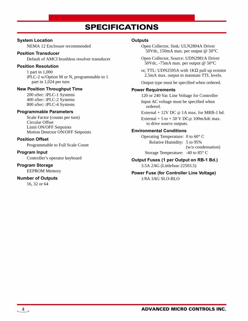
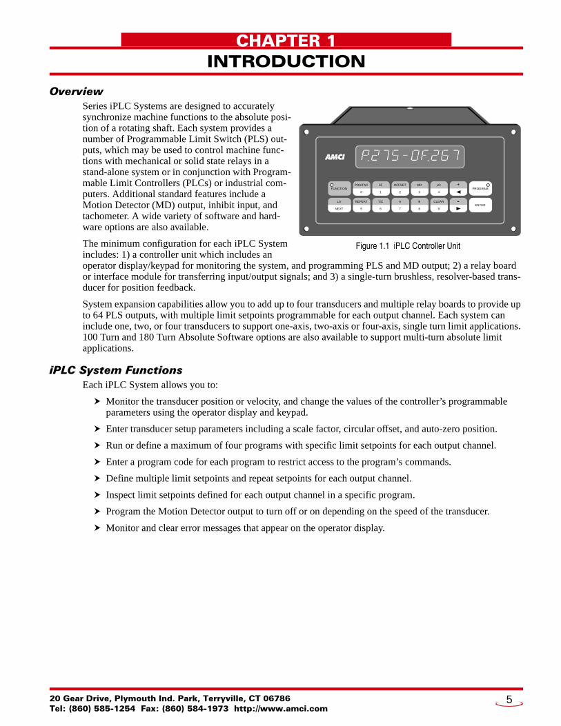
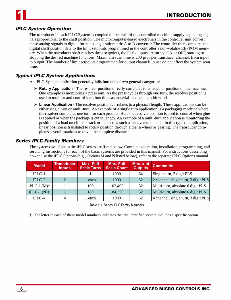
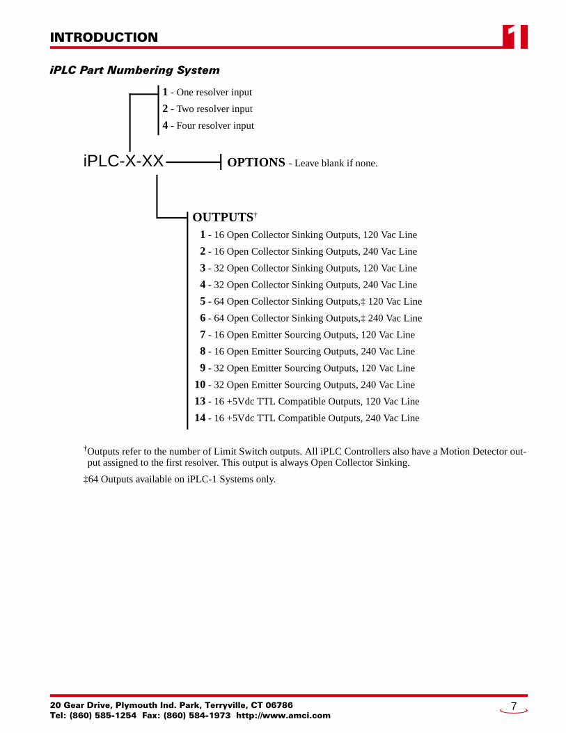
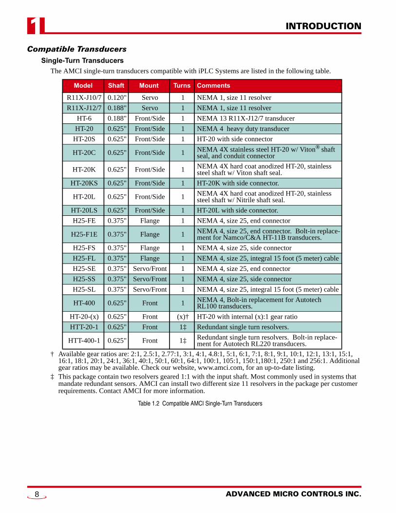
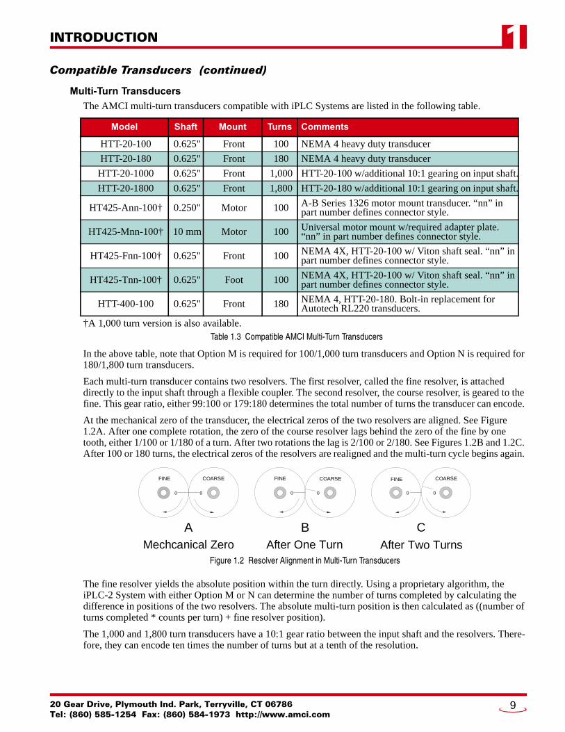
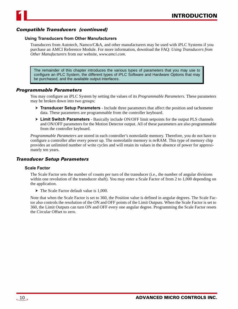
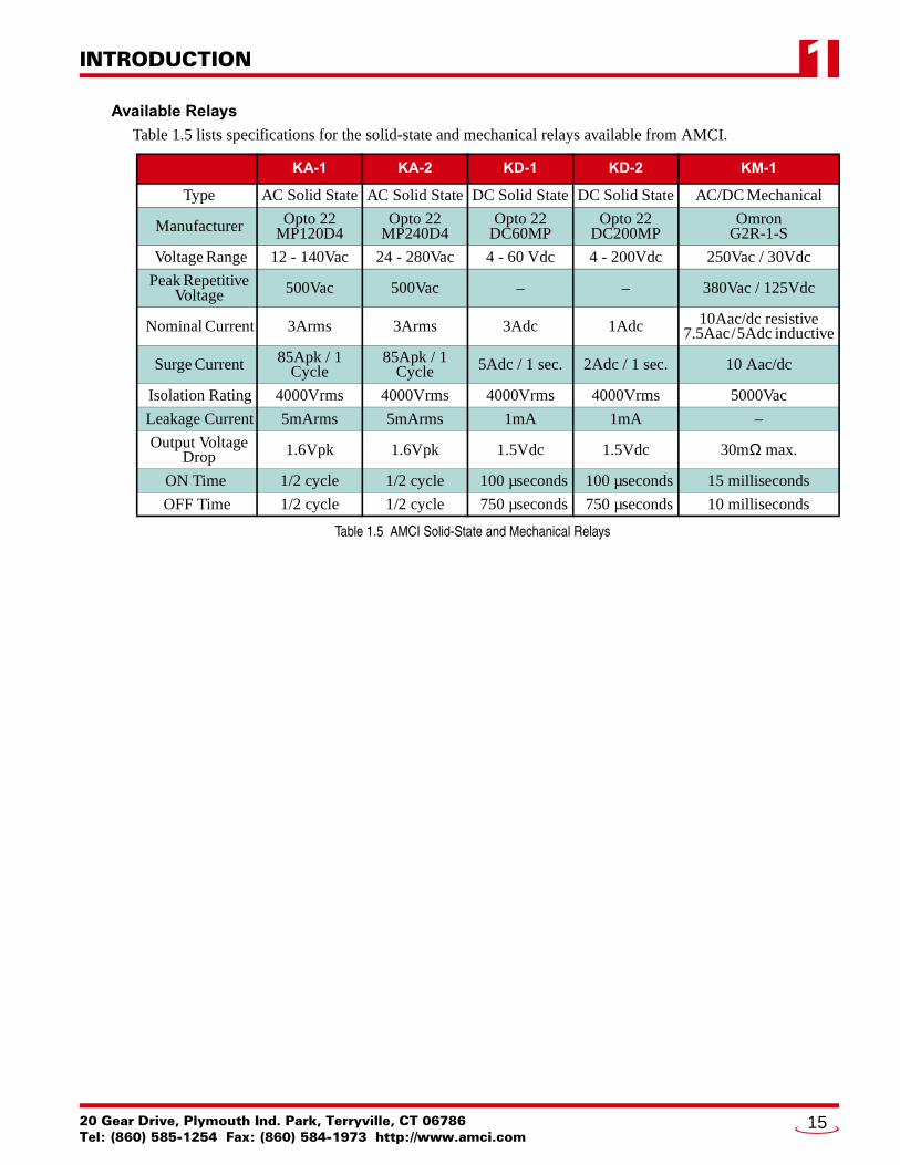

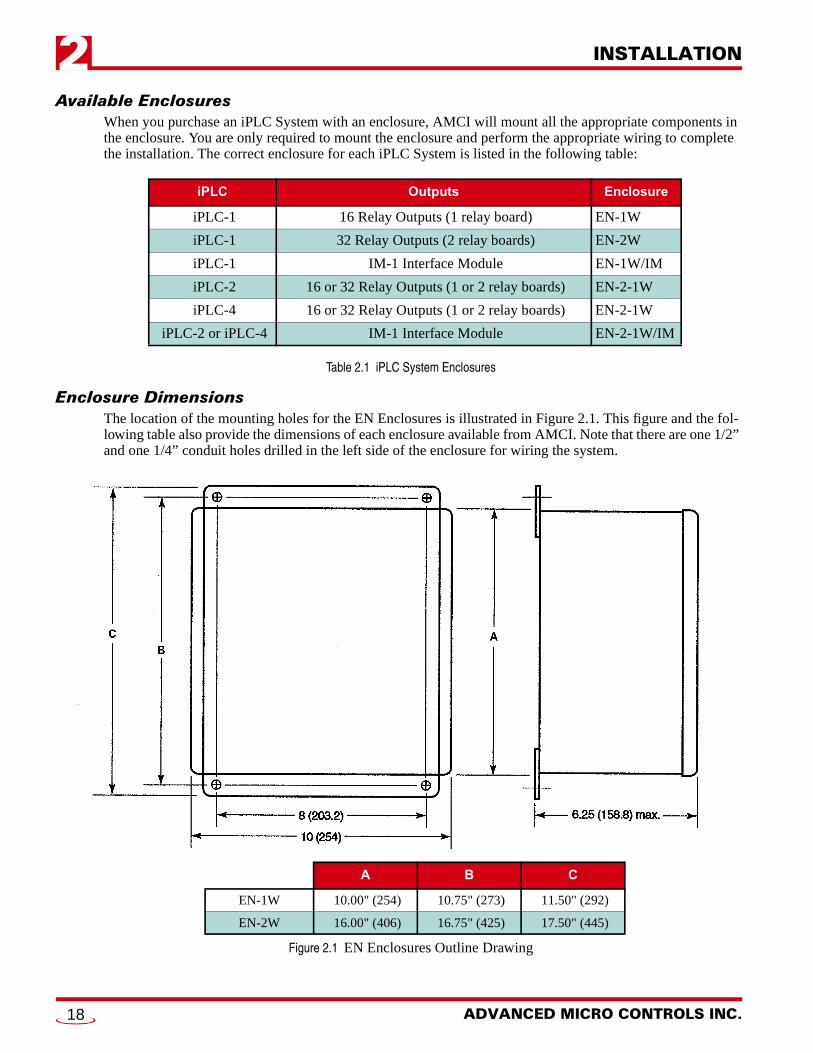
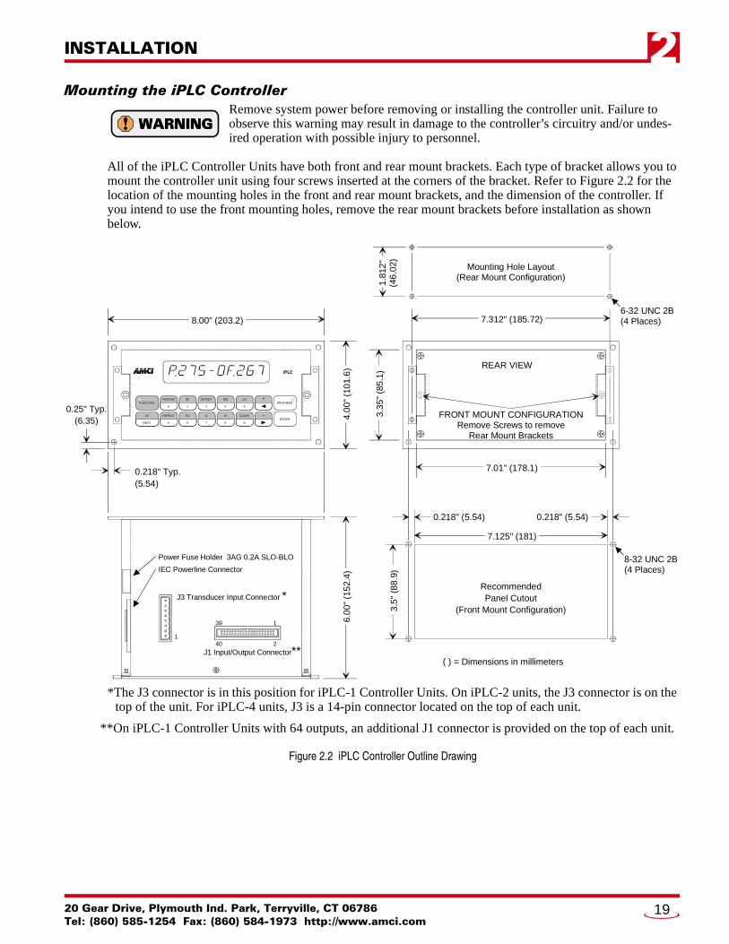
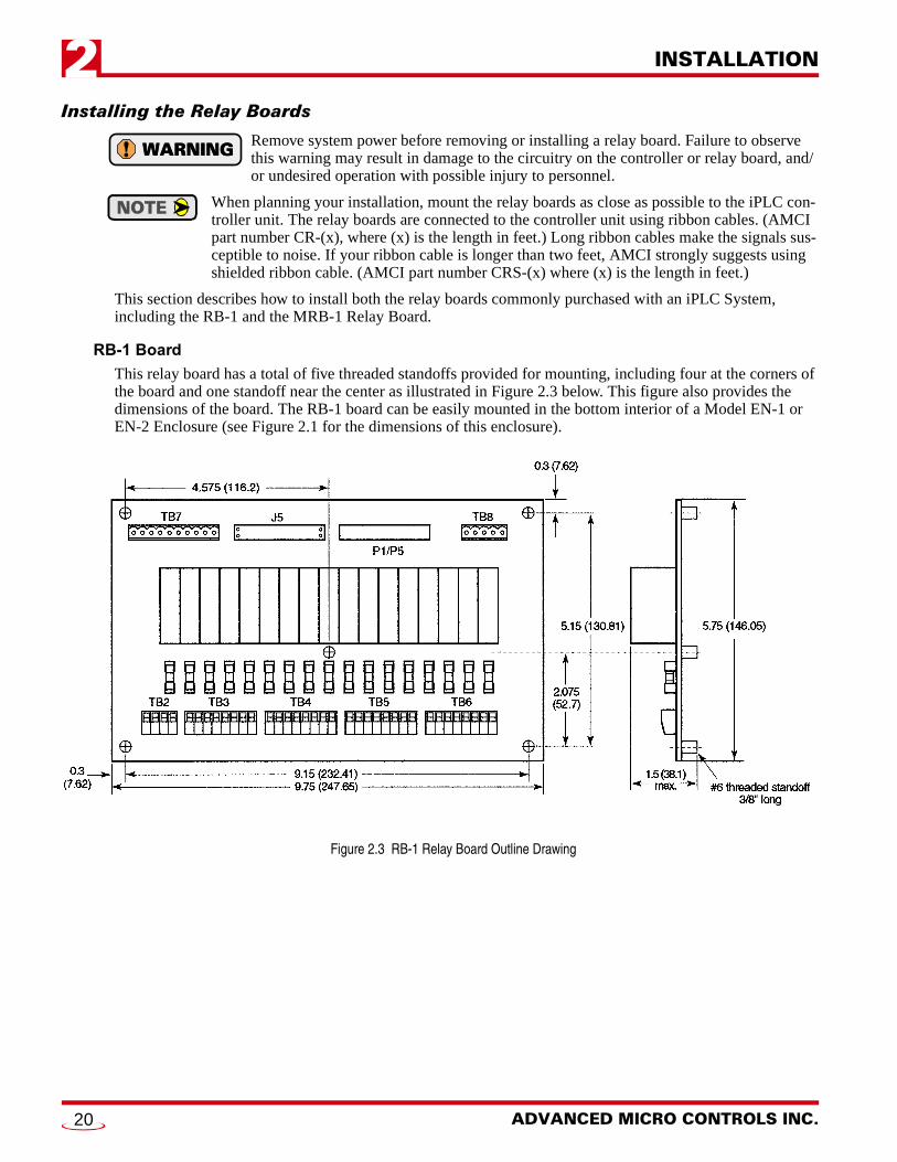
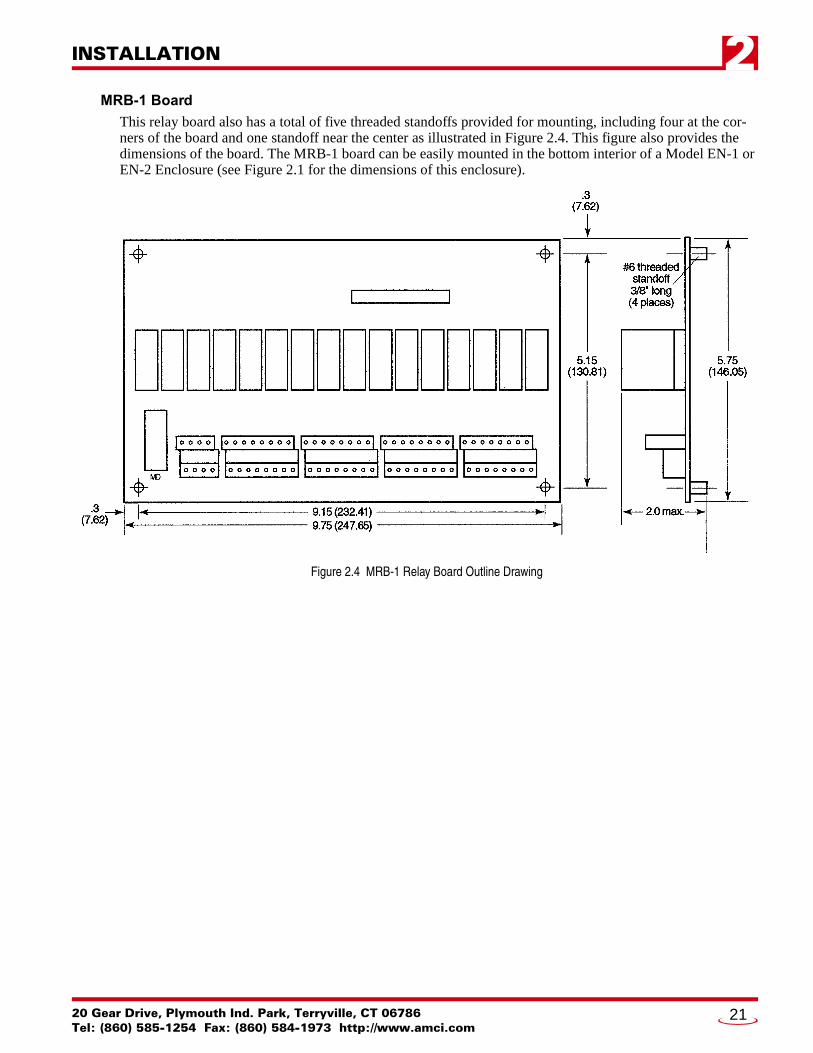
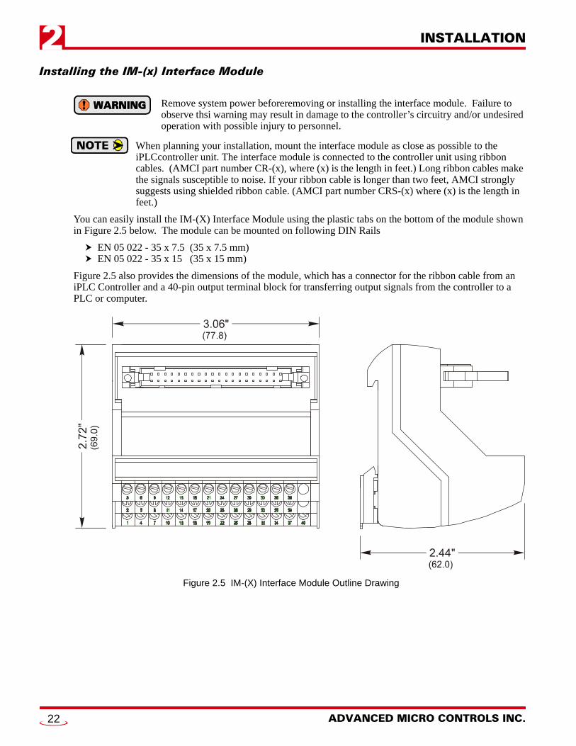
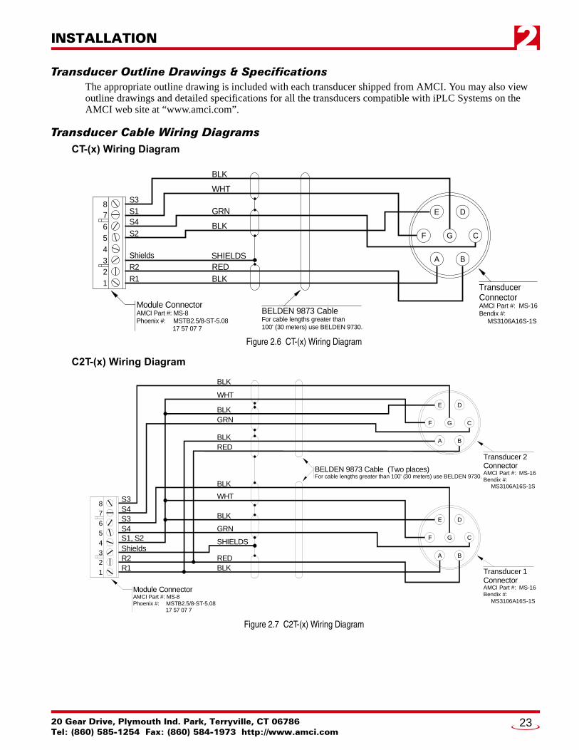
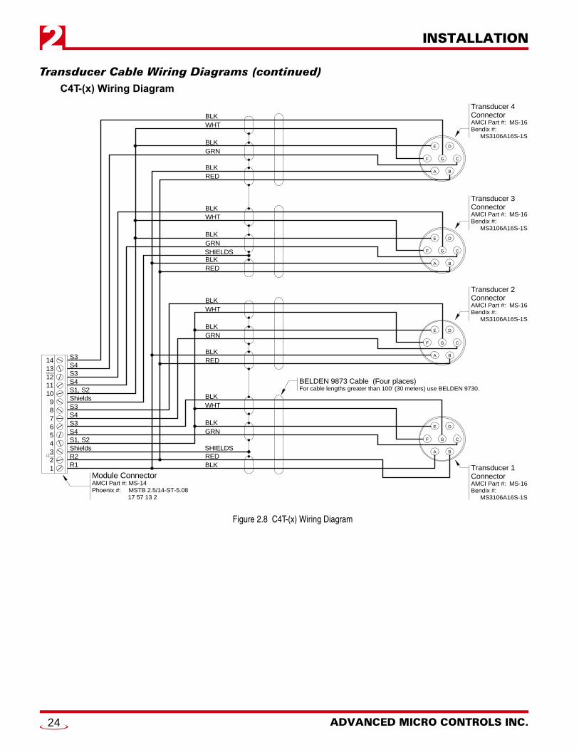
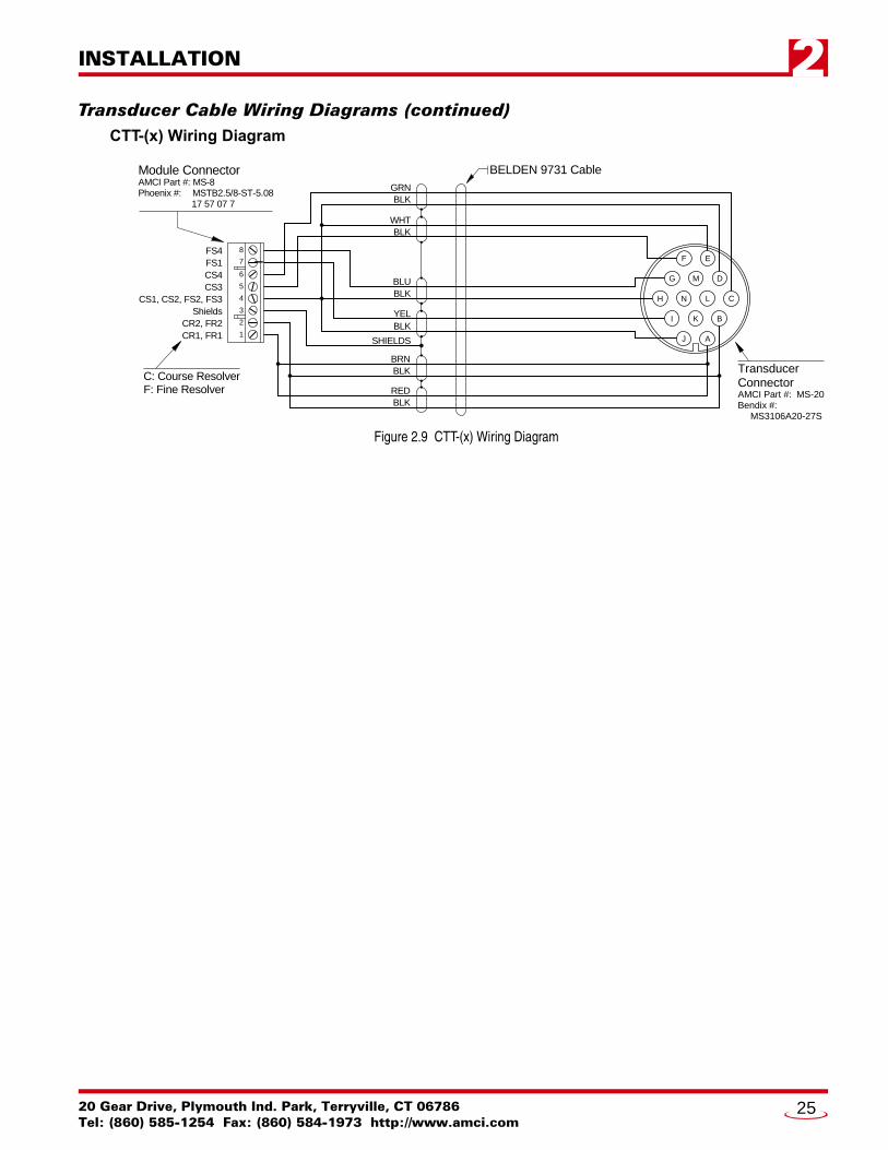
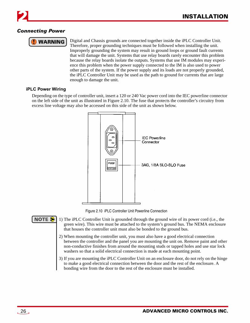
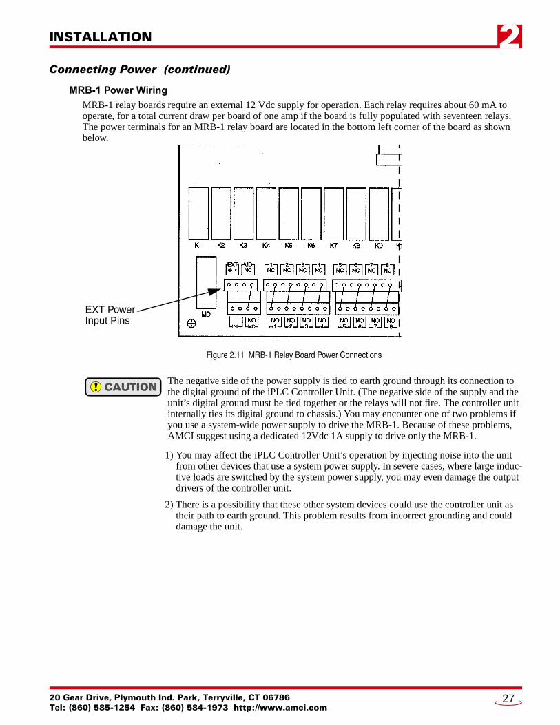

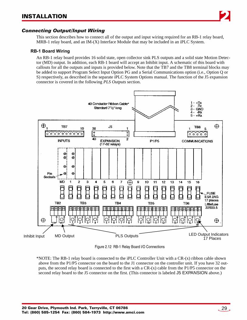
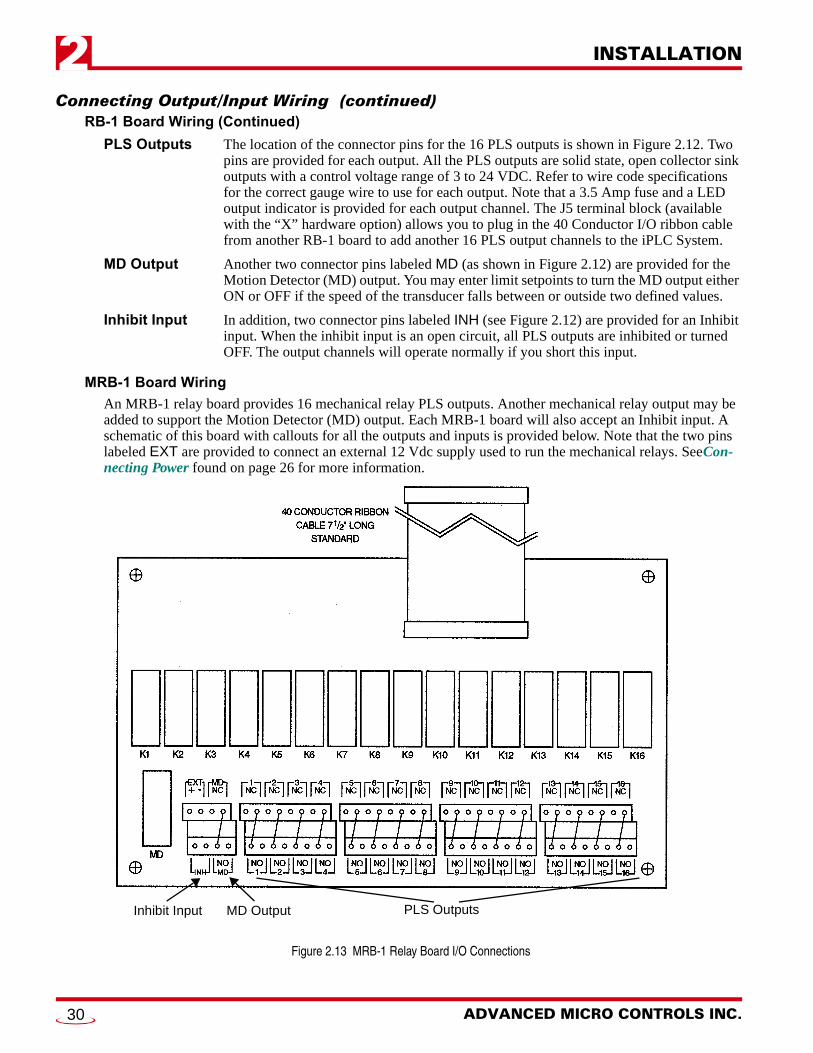
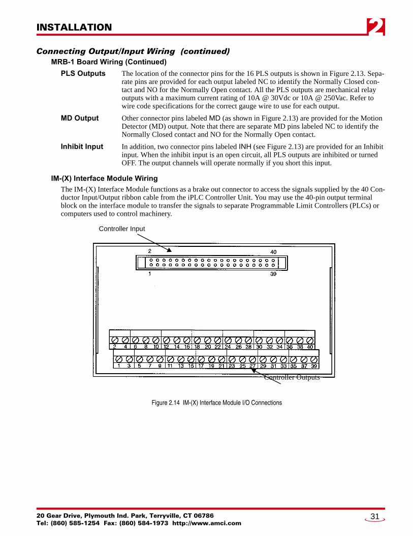
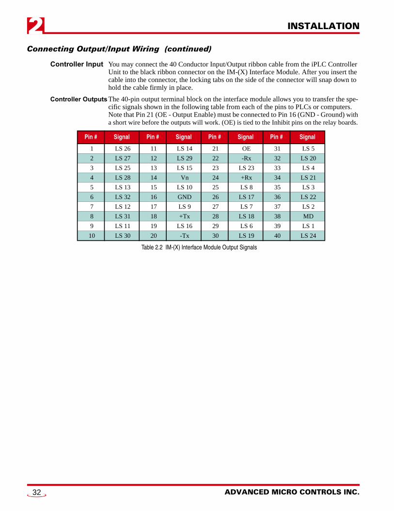
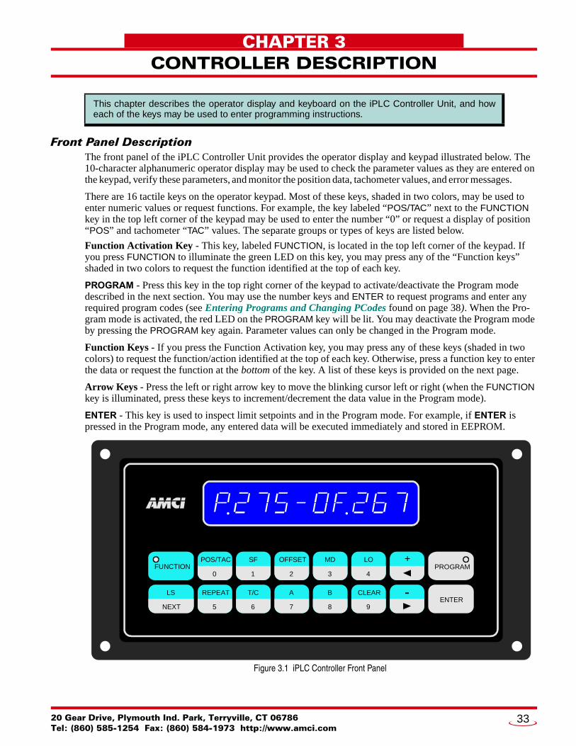

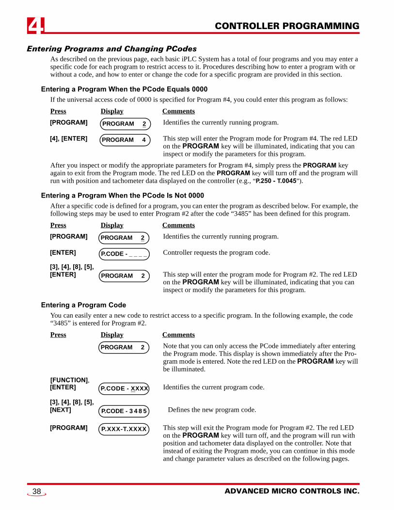
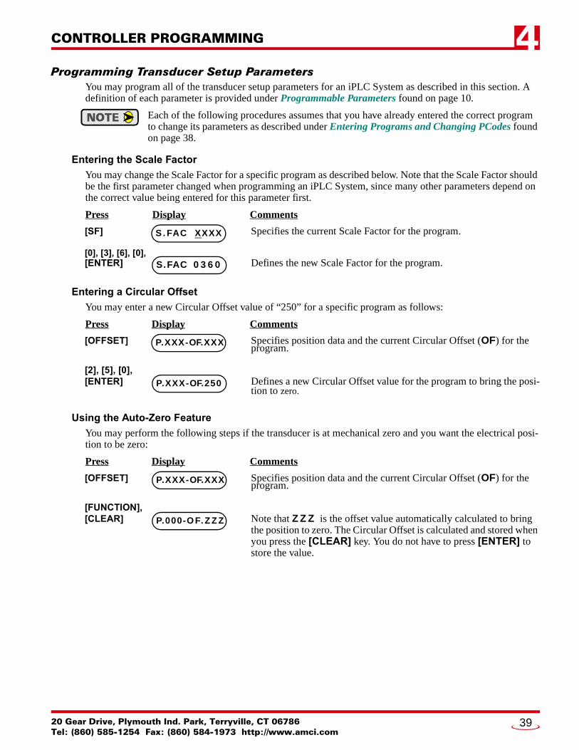
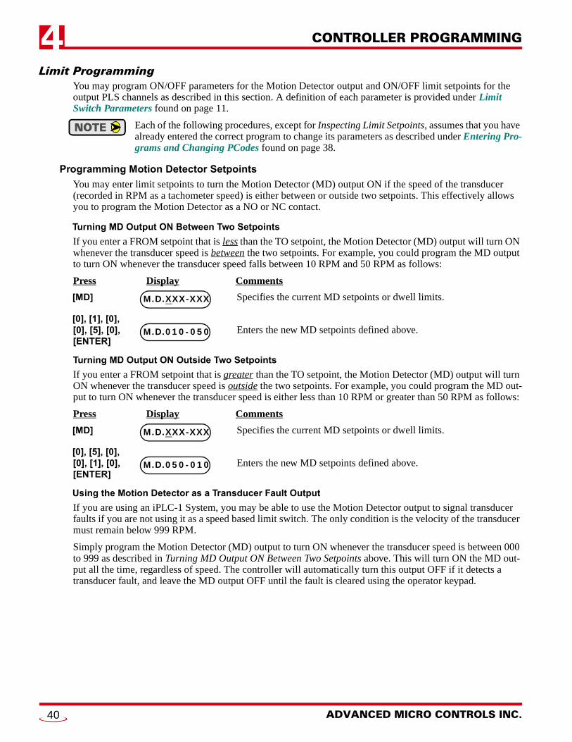
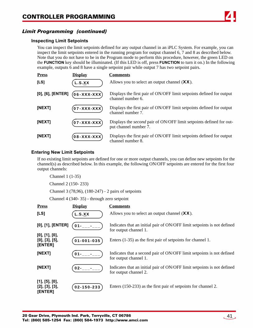
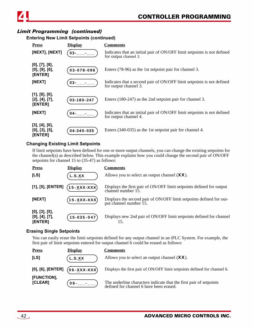
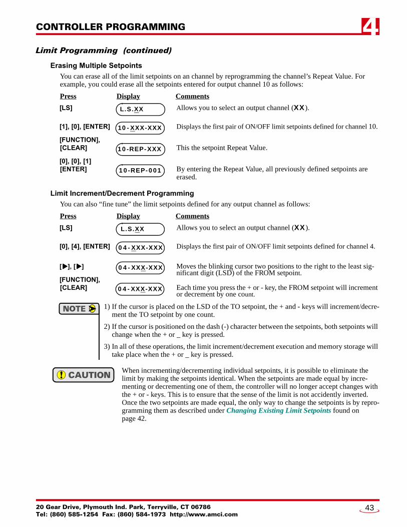

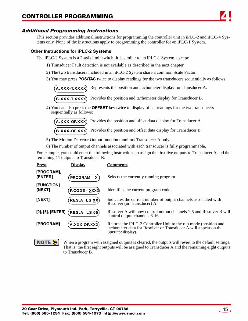
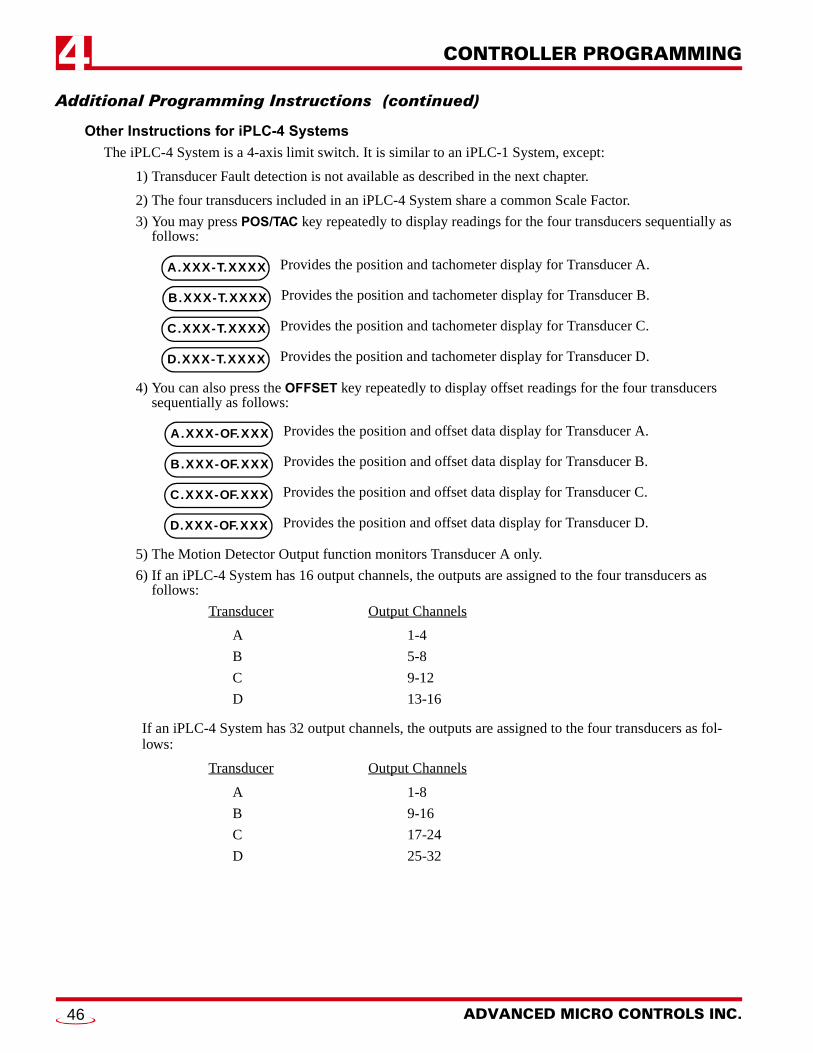
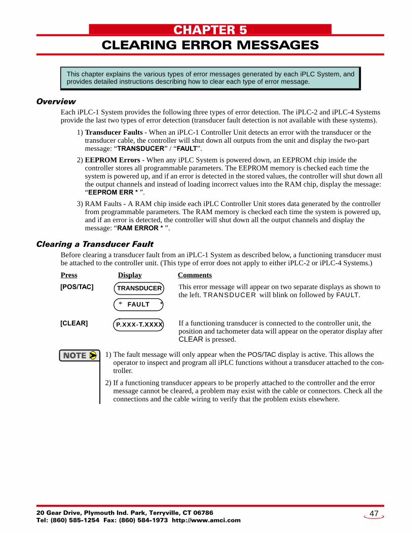
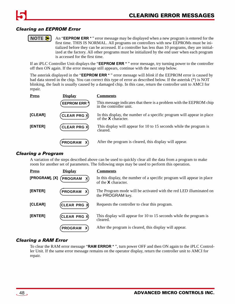
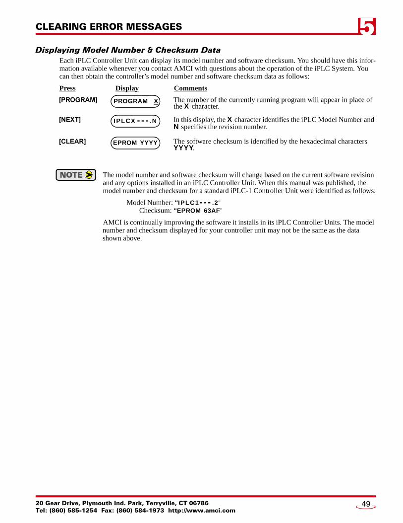


![Intertenancy Barrier Systems for Terrace Homes - GIB® · — Cost effective. ... Appraisal No.940 [2016] Appraisal No.940 [2016] Appraisal No.940 ... Intertenancy Barrier Systems](https://static.documents.pub/doc/80x56/5adfc64f7f8b9a8f298d5c1f/intertenancy-barrier-systems-for-terrace-homes-gib-cost-effective-appraisal.jpg)