Page 1
L A B S
OPERATION MANUAL
MODEL 86 SCM
Sonic Composition Monitor
(2/22/99)
Mesa Laboratories, Inc.
12100 W. 6th Ave.
Lakewood Colorado 80228 U.S.A.
(800) 628-8393
(303) 987-8000
FAX: (303) 987-8989
www.mesalabs.com
1999
Part Number 600151-001, Rev. C
M E S A
Page 3
Table of Contents
Section 1: Introduction 1
1.1 Unpacking/Receiving Checklist 1
1.2 Physical Description 2
Section 2: Installation/In-Line Fixtures 5
2.1 Installation Planning 5
2.2 Tranducer Installation 6
2.3 Bubble Chamber 10
Section 3: Operation and Menus 12
3.1 The Keypad and Menus 12
3.2 The START/STOP Mode 14
3.3 The HELP Menu 15
3.4 The SETUP Menu 15
3.5 The CALIBRATE (CAL) Menu 19
3.6 The PARAMETERS Menu 26
3.7 The DISPLAY Menu 29
3.8 The ALARM Menu 31
Appendix A: Testing and Data Development 35
Appendix B: Process Fine Tuning 43
Appendix C: RS-232 Communications Syntax 45
Appendix D: 86SCM Menu Flowchart 47
Appendix E: 51
Specifications 51
Configuration Information 53
Access Code Log 55
Start Up Information 56
Appendix F: Calibration Check Recipe 59
NEMA 7, NEMA 4X enclosures for 86SCM drawing
86SCM Field Wiring Diagram
Page 4
Warranty
All products manufactured by the seller are warranted against defects in materials and
workmanship for a period of one (1) year from the date of shipment to the original purchaser.
Any Mesa Laboratories, Inc. product which proves to be defective during the warranty period
will be repaired or replaced free of charge, provided that the product is returned freight prepaid to
Mesa Laboratories, Inc. factory from which original shipment was made. The customer will also
pay return freight costs following the repair or replacement of the product.
This warranty will become void if the product is used for other purposes or in environments other
than those for which it was designed, or if its circuits or mechanisms are tampered with except as
normally required for installation purposes. Products of other manufacturers which are supplied
by Mesa Laboratories, Inc. will be covered by the original equipment manufacturer's warranty.
Materials of construction are warranted to be compositions stated by Mesa Laboratories, Inc. and
warranted as to their integrity. Conditions in the medium to be analyzed are beyond the control
of Mesa Laboratories, Inc. and, hence, resistance to corrosion/erosion is specifically not
warranted.
No other warranty is expressed or implied.
Page 5
1
Section 1: Introduction
Thank you for selecting Mesa Laboratories, Inc. Model 86 Sonic Composition Monitor (86SCM)
for your process concentration-measurement requirements.
The 86SCM is a versatile analyzer, capable of operating in a wide variety of liquids. Though
designed for single-variable solutions (alcohols, organic and inorganic acids and bases, resins
dissolved in solvents, etc.), under some conditions the 86SCM can be used to resolve emulsion
concentration, percent suspended particles in solution or multivariable solutions.
The 86SCM employs a unique approach to concentration measurement - concentration output is
a calculated value derived from a process model that takes into account the effects of both
concentration and temperature on sound velocity. Concentration can be expressed in a wide
variety of units, including weight percent, density/specific gravity, and special units like °Brix or
°Baume.
Its seal-free, all-welded standard transducer allows the 86SCM to be used in high-temperature
and high-pressure applications that cannot be accommodated using other analyzers. The 86SCM
has no moving parts, and the transducers are available in a variety of corrosion-resistant
materials. These advantages insure long-term accuracy and reliability with minimal or no
maintenance requirements.
1.1 Unpacking/Receiving Checklist
Before shipment, each 86SCM is given a thorough functional and cosmetic inspection.
Carefully examine each item for damages that may have occurred during shipment.
If damage has been sustained during shipment, a claim should be immediately filed against the
carrier. Please contact Mesa Laboratories, Inc. with a description of the damages, along with
the instrument serial number and Mesa factory number which are found on both the
Configuration Information and Start-Up Information sheets in Appendix E.
Mesa Laboratories Inc., Nusonics Division Service Department
12100 W. 6th Ave.
Lakewood CO 80228
Phone: (800) 628-8393 (Toll Free)
(303) 987-8000
FAX: (303) 987-8989
E-Mail: [email protected]
[email protected]
If the 86SCM is to be stored prior to installation, it should be stored in its original packing, in
a dry indoor location. Should it become necessary to return the 86SCM, the use of the original
packing material will minimize the risk of damage in shipment.
Page 6
2
1.2 Physical Description
The 86SCM consists of two major assemblies: the transmitter and the transducers. The
transmitter is typically installed within a few feet to 100' of the transducers, depending on the
length of the interconnecting cable provided with each 86SCM.
Transducers
The transducers are the wetted elements of the 86SCM. They are installed in the process line,
or in a sampling loop. The standard transducer is called the "HSX/T", an acronym for "high-
sensitivity transducer / temperature".
The HSX/T is an insertion style transducer that combines both Sound Velocity (SV)
transducer and a miniature RTD in the same transducer body. The entire transducer body is
welded - there are no elastomeric seals to fail under extremes of temperature, pressure or
corrosive environment. The miniature RTD is protected from the process by an integral
thermowell constructed of the same material as the transducer body, and welded to the body.
The thermowell is filled with a thermally-conductive compound that improves the response
time of the RTD.
A second transducer design is provided in a "spool" configuration. Spools are flow-through
fixtures having the same diameter as the pipe or sample loop. The design incorporates
separate transmit and receive transducers placed directly opposite one another, flush with the
pipe wall. The RTD is mounted separately. There are two types of spool; the all-metal spool
includes transducers that are bolted to a weld boss, and Kynar and polypropylene spools
incorporate integral transducers that are built into a machined well in the spool wall. Figures
of both designs appear in Section 2.
Locating transducer serial number
Most transducers include wire markers that identify the transducer serial number. The 5-digit
serial number is indicated on a yellow wire that emerges from the interior of the transducer
and terminates at TB4 inside the transducer connection head. Flanged transducers will have
the serial number stamped on the side of the metal flange.
Optional pressure transducer
The 86SCM has the capability to compensate concentration for variations in process pressure.
The effect of pressure on sound velocity is far less significant than that of temperature, only
about 0.01 meter/second/psi (m/s/psi) in aqueous solutions. In most processes, pressure
changes do not significantly contribute to measurement error, so pressure compensation is not
necessary and the pressure transducer is not provided.
Transmitter
The transmitter is the "brain" of the 86SCM. The major functions of the microprocessor-
based transmitter are signal output to the transducers, processing of the returned signals and
display of process variables via alphanumeric liquid-crystal display (LCD) and output/alarm
Page 7
3
to external devices. The 86SCM includes RS-232 communications for two-way
communications with terminals, computers, and other devices that support RS-232; industry-
standard 4-20 mA outputs of process variables; and Form-C alarm relays for high- and low-
setpoints and failure indication. See Appendix E, Specifications, for more information on the
outputs of the 86SCM and power requirements of the transmitter.
The transmitter sends an electrical signal via cable to the sound velocity transducer. The
signal excites the "send" piezoelectric element of the transducer, which emits compression
waves. This acoustic signal is continuously transmitted through the "acoustic path" immersed
in the process liquid and reflected to the "receive" element, where acoustic energy is converted
to an electrical impulse and carried to the transmitter via cable, completing the circuit.
Based on very precise time-measurement, the 86SCM determines the speed of sound through
the process liquid. Sound speed can change as a function of liquid composition and of
temperature; since the 86SCM is also receiving continuous temperature input from the RTD,
it can directly correlate changes in sound speed to changes in process liquid composition.
Most single-variable analyzers provide a scaled output that is accurate only as long as the
relationship between measured quantity and composition is linear. A plot or graph of this
relationship is called a concentration curve. Nonlinearity produces error. The slope of the
concentration curve can also change as a function of temperature. This is called a second-
order nonlinearity. The 86SCM provides accurate output in most applications - linear or
nonlinear - because it directly calculates concentration based on a process model, which is
called a recipe. A single transmitter can contain as many as sixteen different recipes, which
makes it especially useful in batching operations where different liquids can be pumped
through a common process line. The recipes can be called up manually by using the 86SCM
keypad, or remotely via RS-232.
Transmitter features
Figure 1-1 shows the major features of the 86SCM transmitter.
The display panel includes a 2-line by 16-character alphanumeric LCD. In addition to
displaying the values of process variables, the LCD displays the contents of each of the
86SCM menus.
Fuses, LED indicators and the power on/off switch are located below the keypad. Facing the
transmitter, the printed-circuit boards (PCBs) are located in a card cage to the left of the
display panel. The transmitter contains four removable PCBs that can be identified by the
color of their upper ejectors. Each PCB has an upper ejector (color-coded) and a lower ejector
(white). The PCBs are fixed in position by guides in the card cage that secure the upper and
lower edges of the PCB. The upper card guide is color-coded to match the ejector of the PCB
that should occupy a particular position in the card cage. Figure 1-1 also shows the
transmitter terminal blocks. The general function of each of the three terminal blocks is:
Page 8
4
Terminal # and Function:
TB1 Outputs: setpoint and alarm relays,
analog outputs
TB2 Main power (ac)
TB3 Inputs: wiring to sensors, RS-232
communications
PCB #, Color and Function:
1 Green Power Supply
2 Red Sound Velocity
3 Yellow I/O or "Analog"
4 White Unused
5 Blue Microprocessor
To remove a PCB, turn off power to the
transmitter, and lift the inner tabs of both
ejectors. This unseats the PCB, which can
be completely removed from the card cage
by grasping the ejectors and pulling the
PCB free from the card guides.
PCB1: POWER SUPPLY
PCB2: SOUND VELOCITY
PCB3: I/O (ANALOG)
PCB5: MICROPROCESSOR
TB1 TB2
TB3
LCD
KEYPAD
POWER ON/OFF, FUSES
Fig. 1-1: Transmitter features
Page 9
5
Section 2: Installation
2.1 Installation Planning
The 86SCM transducer can be provided in either lab or process configurations. There are several in-
line (process) mounting configurations, each of which is described in this section of the manual.
Mounting configuration selection is based on process piping, proposed location, and the physical
characteristics of the application.
By the time the user has received his 86SCM, these factors usually have been addressed and the
appropriate in-line mounting fixture specified. However, there are certain general installation
guidelines that bear repeating, as well as some specific installation recommendations for several of the
mounting fixtures.
2.1.1 Transducer Location
The 86SCM is not suited for areas where entrained gas bubbles are present. Avoid locating the in-
line transducers near devices that can cause cavitation. Some applications (concentrated sulfuric
acid and sodium hydroxide dilution are two examples) normally contain entrained gas bubbles. The
bubble removal chamber is recommended for such applications.
If the 86SCM is used in the measurement of undissolved solids or emulsions/suspensions, the in-
line transducers must be located at a point where the solid or emulsified particles are
homogeneously distributed across the acoustic path. In other words, flow rate or mixing must be
sufficient to keep particles suspended, or to keep an emulsion from breaking.
Whenever possible, the 86SCM should be located in a sampling loop outside of the process stream.
This is advantageous because the loop can be isolated from the process so that the process is not
interrupted in the event that transducer maintenance or cleaning is required.
Some mixing tanks or reactors may be less-than-ideal installation sites for the 86SCM. Depending
on the mixing method used, entrained gas bubbles can be present, and tanks may be more prone to
temperature/concentration gradients than are process streams. Installations in tanks or reactors
should be discussed with the factory prior to installing the transducers.
The transducers must be completely immersed in liquid. This must be considered when mounting
the transducers in a reactor, tank or if the process line will occasionally be empty.
2.1.2 Transmitter Location
The 86SCM should not be located in areas of excessive electrical or radio-frequency (RF) noise.
Though the transmitter's NEMA 4X enclosure has an RF-shielded coating and the coaxial transducer
cables are shielded, performance may be impaired in high-RF environments or in close proximity to
rotating electrical equipment.
Page 10
6
2.1.3 Cables
Each 86SCM is provided with a specified length of transducer cable that is spade-lug terminated at
both ends.
DO NOT CUT CABLES OR EXTEND CABLE LENGTH BY SPLICING.
The transducer cable is a factor in each 86SCM standardization calibration (performed by the
factory). Altering cable length will invalidate the calibration and may result in erroneous analyzer
output. Plan your installation of the transmitter and in-line fixture so that cable length need not be
altered.
DO NOT RUN AC-POWER WIRING AND TRANSDUCER CABLES THROUGH THE
SAME CONDUIT!
Each process analyzer enclosure has three conduit holes at its base. Cabling to the 86SCM should
occupy separate conduits as follows:
Power wiring (ac)
Sound velocity and temperature transducer cabling
Output signal cabling (4-20 mA, alarms, and RS-232)
If the 4 - 20 mA output is to be used, make sure that the load of the peripheral equipment does not
exceed the 600Ω specified maximum for the 86SCM 4-20 mA output. Improper loading may
result in erroneous output.
2.2 Transducer Installation
This section describes the correct way to orient your transducers in the process and how to wire the
transducers to the transmitter. You can determine which in-line fixture you have by consulting the
Configuration Information sheet in Appendix E.
All transducer cables are provided with spade-lug terminations at both ends, with the exception of lab-
style transducers, where the wiring at the transducer end runs directly into the handle of the sensor,
having been terminated at the transducers by the factory. Otherwise, the ends of the cables are clearly
marked by labeled, shrink-wrap tubing on the shielded portion of the cable.
At the transmitter end, the label "TRANSMITTER TB3" appears. This indicates that all transmitter
wiring is to be made at terminal block 3 (TB3). At the transducer end, the label "TRANSDUCER
TB4" appears. This indicates that wiring is to be made at transducer terminal block TB4.
Beyond the cable shielding, the individual wires are exposed. These wires are also marked, with
circular wire markers indicating the appropriate terminal block location for each wire. These locations
are numerical - for instance, a transmitter wire having the marker "2" indicates that the wire should be
terminated at transmitter terminal block 3 (TB3) location 2, or TB3-2.
Page 11
7
Some in-line fixtures like the spool piece have more than one connection head/terminal block; the
spool piece has three, one for the RTD and two for the separate sound velocity transducers. Each of
these terminal blocks has the designation "TB4", but different wiring block numbers that reference to
the individual wire markers.
2.2.1 Transducer Orientation and Wiring
This section includes figures that illustrate the correct wiring to each type of transducer, as well as
proper orientation with respect to the horizontal-pipe installations. Where applicable, specific
installation notes for each fixture are given. Lab-style transducers are a special case, since they are
wired at the transducers by the factory.
135o
135o
o45
o45
AXISPIPE
VERTICAL
OF TRANSDUCERS
SEEN FROM DOWNSTREAM SIDE
VIEW ALONG AXIS OF FLOW,
1
102 3 4
1 2 3 4 10
HORIZONTAL PIPE AXIS
SOUND VELOCITY
TRANSDUCER CABLES TB4
RTD CABLE
TB4
Figure 2-1: Flanged Transducer Orientation.
Flanged Transducer Assemblies
Flanged HSX/T transducers are the simplest process configuration provided. The flanged
transducers are installed on a riser on the process line (or bypass), in a "T", or a flanged connection
into a tank or chamber.
Both of the transducer cables include two wires; each has a wire marked for termination at TB4-1;
these wires are tied together, sharing a common spade lug. The remaining wires are marked for
termination at TB4-2 and TB4-10.
The RTD cable includes two wires, marked for termination at TB4-3 and TB4-4.
Orientation in horizontal pipes: The ideal orientation in horizontal pipes is such that the
transducer assembly is in the horizontal plane. This orientation makes it less likely that bubbles
will adhere to the acoustic windows or reflector, interfering with measurement. The flange-
mounted assembly can be rotated up to 45° out of the horizontal plane, as shown in Figure 2-1.
These guidelines do not apply to vertical pipe installations.
Page 12
8
FLOW
FLANGE-MOUNTED HSX/T SOUND
VELOCITY TRANSDUCER
VIEW FROM FLANGE TOP
FLOW
Figure 2-2: "T" or Riser Installation
Each flange-mounted transducer assembly includes a tag on the top of the flange indicating the
correct orientation with respect to the axis of flow. Refer to Figure 2-2 for an example of the flow
direction tag. Orienting the flange-mounted assembly as specified places the RTD thermowell
downstream of the sound velocity sensor, ensuring that measurement is not affected by potential
cavitation or turbulence caused by the thermowell. The flange-mounted assembly should be
installed in accordance with the flow direction arrow in both horizontal and vertical pipe
installations.
Spool Pieces
Spool pieces have separate
transducers on opposite sides of
a pipe section (spool) provided
by Mesa Laboratories. One
transducer is a dedicated
"sender" and the other a
dedicated "receiver".
Spools are sized according to
the inside diameter of the
existing process line or sample
loop. The standard spool
shown in Figure 2-3 is
fabricated from a metal alloy,
generally stainless steel,
Hastelloy B or C, or Carpenter
20.
The standard spool transducers are flanged to weld bosses on the lateral sides of the spool.
VIEW FROM UPSTREAM
SOUND VELOCITY
TRANSDUCERS
HORIZONTAL
AXIS
RTD
VIEW FROM SPOOL SIDE
FLOW
VIEW FROM SPOOL TOP
SOUND VELOCITY
TRANSDUCERS
THERMOWELL
TRANSDUCER TB4
3 4
SOUND VELOCITY
TRANSDUCER CABLES
RTD CABLE
3
4 2
1
21
TRANSDUCER TB4
10
9
109
TB4 TB4 TB4
RTD AND
THERMOWELL
Fig. 2-3: Standard spool piece.
Page 13
9
DO NOT REMOVE THE TRANSDUCERS FROM THE WELD BOSSES UNLESS
INSTRUCTED TO DO SO BY THE FACTORY.
Standardization calibration of
each analyzer includes a very
precise determination of the
distance between the two
transducers. Removal of one or
both transducers will
necessitate recalibration.
Figure 2-4 shows a special
spool configuration available in
both Kynar and high-density
polypropylene. The spool body
is machined to accommodate
integral sound velocity
transducers.
Though the connection heads employed for the two spools may differ in style, the wiring
terminations and terminal block identification for both types of spool are identical. Two transducer
cables are included. One terminates at TB4-1 and TB4-2, and the other at TB4-9 and TB4-10.
Each spool includes a single, 2-wire RTD cable, terminating at TB4-3 and TB4-4.
Orientation in horizontal pipes: In horizontal pipes, the spool must be oriented such that the
sound velocity transducers are in the horizontal plane. This does not apply to vertical pipe
installations.
Figure 2-3 illustrates the correct orientation of the spool with respect to the direction of flow
through the pipe. Note that the RTD/thermowell is downstream of the sound velocity transducers.
All spools must be installed in this orientation, regardless of whether the installation is horizontal or
vertical.
TB4
109
9 10
SOUND VELOCITY
TRANSDUCER CABLES
4
3
RTD CABLE
43
TRANSDUCER TB4
21
TRANSDUCER TB4
1 2
TB4
HORIZONTAL
AXIS
VIEW FROM DOWNSTREAM
VIEW FROM SIDE
TB4
Fig. 2-4: Kynar/polypropylene spool.
Page 14
10
1-inch Sample Chamber
The 1-inch sample chamber
utilizes the HSX transducer and
a separate RTD/thermowell,
while all other configurations
except spools use the HSX/T,
incorporating the RTD and its
thermowell in the sound
velocity sensor body.
As illustrated in Figure 2-5, the
1-inch sample chamber
includes separate terminal
blocks for both sound velocity
and temperature sensors.
Both of the transducer cables include two wires; each has a wire marked for termination at TB4-1;
these wires are tied together, sharing a common spade lug. The remaining wires are marked for
termination at TB4-2 and TB4-10.
The RTD cable includes two wires, marked for termination at TB4-3 and TB4-4.
Orientation in horizontal pipes: Per Figure 2-5, the 1-inch sample chamber should be oriented
such that both the sound velocity and temperature sensors lie in the horizontal plane. This does not
apply to vertical installations, where any orientation is satisfactory.
The flanged inlet and outlet of the sample chamber are marked "IN" and "OUT". The sample
chamber should be oriented accordingly with respect to the direction of flow.
Special installation notes: The inlet and outlet of the sample chamber are offset from one another
by 1", center-to-center. This offset may under some conditions cause excessive
turbulence/cavitation, which can affect instrument performance. Mesa recommends that flow
velocity through the sample chamber be limited to no greater than 3 feet/sec (1 m/s or 7.5 GPM in a
1" line).
2.3 Bubble Chamber
A common application for the 86SCM is the measurement of acids. Many acid processes have a
tendency to entrain air bubbles. If enough of these bubbles are present, they will adversely affect
the performance of the sonic analyzer. The NuSonics bubble chamber can mitigate this effect
and is provided as an option. The bubble chamber accepts a standard flange mounted sensor, and
wiring is as described in the previous section.
The presence of bubbles in a process can usually be determined by the appearance of the acid or
liquid. When transparent liquids have a high bubble content, they will appear milky or
translucent.
VIEW FROM SAMPLE CHAMBER
HORIZONTAL
AXIS
INLET (UPSTREAM) SIDE
IN
OUT
THERMOWELL
RTD
SOUND VELOCITYTRANSDUCER
TB4
RTD CABLETRANSDUCER CABLES
SOUND VELOCITY
104321
43 2 10
1
TRANSDUCER TB4
TRANSDUCER TB4
3 4TB4
Fig. 2-5: 1-inch sample chamber.
Page 15
11
The bubble chamber, shown below, is installed in the system such that the Vent and Drain are
normally valved shut. Acid enters the chamber through the inlet, the bulk of which flows into
the top of the internal tube and to the outlet. Some acid flows down through the chamber, past
the sensor, into the internal tube and to the outlet. The chamber itself is installed in a bypass
loop with a throttling valve such that the flow through the system can be controlled.
The flow through the chamber is set such that the rise rate of bubbles is greater that the descent
rate of the acid in the chamber. The presence of bubbles in the acid at the sensor can be
determined by observing the attenuation value reported by the sonic analyzer. When bubbles are
present, attenuation (see Section 3.7.4, page 30) will be high (around 100%); when the acid is
clear, the value will be low (typically less than 25 %).
INLET
OUTLET
VENT
DRAIN
24.00
2.00
2.00
6.003.72
8.627.75
17.12Dimensions are in Inches
Not To Scale
SENSOR
Page 16
12
Section 3: Operation and Menus
This section provides a step-by-step description of each of the 86SCM menus. It should be read by all
users who are not familiar with the 86SCM, and those who will be performing on-site calibration (see
Calibration, below). If an operator wants only to locate a particular step within a menu, refer to the
Menu Flowchart in Appendix D. Since this section provides much more detail than the Menu
Flowchart, it should be consulted by operators that have specific or technical questions about a menu
step.
Calibration
Most 86SCMs are factory-calibrated for the applications in which they are to be installed.
Application calibration data are usually derived from Mesa Laboratories' lab testing of customer-
supplied samples. In some cases, application calibration data must be obtained on site. Appendix
A, Testing and Data Development, describes the necessary procedures for obtaining on site data and
developing calibration coefficients.
In order to determine whether on site application calibration is required, consult the Start-Up
Information Sheet in Appendix E of this manual.
If on site calibration is required, this section of the instruction manual should be carefully reviewed
before attempting to gather data, in order to become familiar with the analyzer menus.
3.1 The Keypad and Menus
Six menus are accessed via the membrane keypad on the faceplate of the analyzer. Three of the menus
- DISPLAY, SETUP and HELP - are accessed by pressing the appropriate key; the names of these
menus are silkscreened in blue. The same keys include the names of three additional menus,
silkscreened in red. These menus - ALARM, PARAM (parameters) and CAL (calibrate) -are accessed
by first pressing the "2ND FUNC" (second function) key, then the appropriate menu key.
Most of the values that appear in these menus can be either read or overwritten using the RS-232
communications link and associated syntax (see Appendix C, 86SCM RS-232 Communications
Syntax). Since the majority of operators use the keypad exclusively, the text appearing in this section
describes the menus and data entry for keypad access.
On the keypad, the "up" and "down" arrow keys, represented as (up) and (down) are used to page
through the steps of any menu. To move forward through a menu, press the down arrow: . To
move backward, press the up arrow: .
When a menu is invoked by pressing its menu key, the steps that appear always follow the same
sequence. In this section, the steps are discussed in the sequence that they appear at analyzer power-
up.
Page 17
13
Display Format
The 86SCM includes a two-line liquid crystal display (LCD) with a 16-character length. Menu
steps are shown in the manual as they appear on the LCD; factory-default values are shown for
steps that require input of a value or variable, such as units of measure. This is an example step
from the CAL menu:
TEMP. UNITS:
"." °C
°F
°K
The part of the step actually displayed on the LCD (the first two lines) is shown in boldface. The
description of this step tells the user that °C is the factory-default unit of temperature, or the unit that is
selected unless otherwise specified by the customer before shipment. A list of unit choices is made
available by pressing the period (".") key on the analyzer keypad. As the period key is pressed, the
successive choices replace the previous choice. Pressing the up or down key enters the unit that is
displayed on the LCD. Pressing the "CLEAR" key restores the original unit to the LCD.
There are four types of menu steps:
Information Only
The HELP menu is an information-only menu. The DISPLAY menu is also information-only, but
the information that it displays (process variables like concentration and temperature) is
continuously updated. It requires no user input. Alarm status displays (ALARM menu) also fall
into this category, but the ALARM menu also contains other steps that require user input.
User Input: YES/NO
Some steps, like the ALARM menu step that allows the user to activate or deactivate alarms, offer a
choice of YES or NO. NO is selected by pressing the numeric "1" key, and YES is selected by
pressing the "2" key. The present (or "active") choice is shown on the second line of the display.
User Input: Multiple Choices
Several SETUP menu steps offer a number of possible choices. For example, there are three units
of temperature that can be selected, °F, °C and °K. The active unit is displayed; by pressing the
period (decimal point) key, the user advances through a list of choices. This syntax is employed for
some steps that have ON/OFF status, like RS-232 host lockout which enables or disables computer
access to critical calibration constants in several menus.
Page 18
14
User Input: Numeric Values
Some steps require the entry of a value through the numeric keypad. If the analyzer has been
calibrated by Mesa Laboratories, Inc., all of these values have been entered by Mesa Laboratories,
Inc. prior to shipment. However, when calibrating an 86SCM (for a new application, for example)
it may be necessary to change existing values, like the individual "recipe" constants (see PARAM
menu, Section 3.6, Page 26). Some steps require customization based on user requirements. For
example, if an operator chooses to enable UNDER RANGE/OVER RANGE alarms, he will
probably change the factory-default limits (0% of span and 100% of span, respectively) to
intermediate values.
Numeric value steps display the present value of a variable, the value stored in the 86SCM RAM.
For example, the AVERAGING TIME step in the SETUP menu has a default value of 0 seconds.
The lower line of the display shows "0.0 secs". Suppose the user wants to change the value to 3
seconds. When the "3" key is pressed, the lower line of the display changes to "3 secs". If the user
presses the CLEAR key before pressing up or down, the previous value, 0.0 secs, is restored to the
display. However, if up or down is pressed after entering a new value, the new value replaces the
previous one and the menu advances to the next step or previous step, depending on whether the up
or down arrow is pressed.
Many numeric values are expressed in scientific notation. The value is displayed with six decimal
places and an exponential term. Users can enter values either in decimal or scientific notation; they
will be automatically converted to scientific notation if it is necessary to fit the display value on the
screen.
3.2 The START/STOP Mode
The START/STOP key switches the 86SCM between the START mode, in which all functions
(alarms, outputs, menus) are active, and the STOP (or IDLE) mode, in which all outputs and menus
except HELP are inactive.
This message appears on initial power-up in the STOP (IDLE) mode:
SONIC ANALYZER
NUSONICS
It is followed by an alternating display of these two messages:
SONIC ANALYZER
READY.
PRESS HELP FOR
INSTRUCTIONS.
To enter the START mode, press the START/STOP key.
Page 19
15
3.3 The HELP Menu
The HELP menu displays a condensed series of operating instruction for the 86SCM. The menu is
invoked by pressing the HELP key. Page through the instructions by pressing the down key.
3.4 The SETUP Menu
The SETUP menu is accessed by pressing the SETUP key. It contains no specific calibration values; it
can be accessed at any time by either keypad or RS-232 and is not subject to code access or host
lockout (RS-232). Most of the steps in the SETUP menu configure the 86SCM for units of
measurement, and output scaling. In the following sections, each step is discussed in the sequence in
which it appears upon entering the menu.
3.4.1 Output Units: Concentration
Concentration units are defined at the opening step of the SETUP menu. To change the unit selections
on the lower line of the LCD, press the period key as instructed. When the desired unit appears, press
the down key to commit the new unit to memory and move on to the next step. The unit choices are
indicated below:
OUTPUT UNITS:
"." wt. %
gm/ltr
vol%
U-D
°Brix
°Baume
°API
SGU
m/sec
Comments Concerning Output Units
Output units are simply labels that are attached to the end of numbers. For instance, assume that
under operating conditions in a hypothetical sulfuric acid application, the analyzer displays "94.38
wt.%" as Output 1. The value 94.38 is calculated by the 86SCM.
94.38% by weight sulfuric acid has a specific gravity of approximately 1.7786. Changing the units
of measurement from wt. % to SGU does not change the indicated value from 94.38 to 1.7786;
instead, the output will read "94.38 SGU". Specific gravity units must have their own set of "K"
coefficients (a unique recipe).
Most of the units labels are self-explanatory. U-D is a label provided for units not listed; it stands
for "User-Defined". °Brix, commonly used in the food industry, is analogous with weight percent
sugar. The "m/sec" label allows the user to label a sound velocity output rather than a concentration
output.
Page 20
16
3.4.2 Output Units: Temperature
This step permits the user to select temperature units. Unit options are viewed by pressing the period
key. To commit a temperature-measurement unit to memory and advance to the next step, press the
down key.
TEMP. UNITS:
"." °C
°F, °K
Changing Temperature Units
Temperature units must match the temperature units used to develop the active application recipe
coefficients. For instance, if the "K" coefficients for a recipe are developed using °F as temperature
units in the data set, then °F must be selected as the temperature unit for display purposes. The
importance of consistent regression/display temperature units is discussed in more detail in
Appendix A, Testing and Application Calibration. Unlike concentration units, temperature units
are more than just labels that follow an input or calculated value. The analyzer converts
temperature input from the RTD to agree with the specified unit of measurement and can display or
output this value.. The value is also passed to the sound velocity equation (see Section 3.5.3) and
the concentration calculation polynomial (see Section 3.6.1).
3.4.3 Output Units: Pressure
This step permits the user to select pressure units. Pressure transducers seldom are provided with the
86SCM in its Sonic Composition Monitor (SCM) configuration. When pressure compensation is
required, a pressure value is continuously input to the 86SCM's concentration-calculation polynomial.
In contrast to concentration units, pressure units - like temperature units - are more than labels
following an input pressure value. The analyzer reads pressure input from the pressure transducer (if
present) and converts the value to agree with the specified unit of measurement. If the pressure term is
employed in the regression data set, the units selected must match the units used in the regression.
PRESSURE UNITS:
"." psig
kPa
kg/sqcm
Bar
3.4.4 Concentration Output Scaling: Output 1
Output 1, the 4-20 mA output at terminal block 1, positions 1 and 2 (TB1-1 and TB1-2; see Field
Wiring Diagram, Figure H-2 at end of manual), delivers a scaled output of calculated concentration.
The first two steps of the SETUP menu allow the user to scale the 4-20 mA output 1 to the desired
process minimum and maximum concentrations. This concentration range must fall within the
concentration range represented by the active "recipe".
Page 21
17
Enter the desired low concentration value at 4 mA. Suppose a user wishes to rescale the output for 3%
to 12% by weight of a substance in a solvent; at the first step (4 mA) press the "3" key, then press
down to store the new value ("3") and advance to the next step.
OUTPUT 1: 4 mA
= 3.00 wt. %
Enter the desired high concentration value at 20 mA. Using the numeric keys, enter "12", then press
down to advance to the next step.
OUTPUT 1: 20 mA
= 12.00 wt. %
Units
The concentration output-scaling steps reflect the concentration units selected in the SETUP menu's
first step. This is the case with all menu steps that display the value of a variable or scaling
parameter combined with specific units. Factory-default units appear in the examples given in this
manual; depending on user specifications, the values and units that appear on the analyzer LCD
may be different than those shown in these examples.
Output 1 Scaling: How it Affects UNDER RANGE and OVER RANGE Alarms
The UNDER RANGE alarm setpoint (see ALARM menu, Section 3.8) can be set no lower than the
output 1 value selected for 4 mA, and the OVER RANGE alarm setpoint can be set no higher than
the output value selected for 20 mA. The UNDER RANGE and OVER RANGE alarms respond
only to output 1. Output 2 can be scaled for the same range of concentration as output 1, but its
value will not activate the alarms.
3.4.5 Concentration Output Scaling: Output 2
Output 2 is the 4-20 mA output at TB1-3 and TB1-4 (see Field Wiring Diagram, Figure H-2). If
output 2 is set for "measured variable", the 86SCM automatically sets its output units identical to
output 1, though output 2 may be scaled for a different range. Output of temperature in lieu of
"measured variable" (concentration) is a user option.
The opening menu step for output 2 allows the user to select either measured variable (MEAS) or
temperature (TEMP) by pressing the "." key:
OUTPUT 2: MEAS
PRESS "." TO CHG
TEMP
Page 22
18
Selecting "Measured Variable"
When MEAS (measured variable) is selected, the 86SCM accepts the active unit of concentration
from the SETUP menu, then allows the user to enter low- and high-output values corresponding to
4 mA and 20 mA:
OUTPUT 2: 4 mA
= 0.00 wt. %
OUTPUT 2: 20 mA
= 100.00 wt. %
Selecting Temperature
When TEMP (temperature) is selected, the 86SCM accepts the active unit of temperature from the
SETUP menu, then allows the user to enter low- and high-output values corresponding to 4 mA and
20 mA:
OUTPUT 2: 4 mA
= 0.00 °C
OUTPUT 2: 20 mA
= 100.00 °C
Most 86SCM RTDs are calibrated to operate over a 0°-100°C (32°-212°F) temperature range.
Consult the Configuration Information Sheet, Appendix E, to determine the calibration range of
your 86SCM RTD.
Temperature Unit Conversion
Please note that changes to temperature and pressure units should not be made arbitrarily; the
application coefficients in the PARAM menu reflect specific temperature units, and where
applicable, pressure units. As previously noted, the SETUP menu units must conform with the
units used in the regression of application coefficients.
3.4.6 Averaging Time
Rapid changes in process conditions can cause fluctuations in both displayed concentration and
measured variable output. Such fluctuations can be smoothed by employing input averaging. The
86SCM includes an algorithm that smoothes the continuous input of sound velocity. The factory-
default setting for averaging time is 1.0 second (no averaging). Entry of a negative averaging time or a
time greater than 30 seconds will cause an error message to appear.
AVERAGING TIME =
1.0 secs.
Page 23
19
3.5 The CALIBRATE (CAL) Menu
The CAL menu is accessed by pressing the 2ND FUNC key, then the CAL key. All 86SCMs are
subjected to a factory sound velocity calibration, or "standardization calibration", which insures that
each analyzer delivers the same sound velocity under the same concentration and temperature
conditions. The standardization calibration should not be confused with the specific application
calibration described by the coefficients in the PARAMETERS menu. The CAL menu contains these
sound velocity calibration constants ("A", "B" "alpha", "N" and "Z" described in Section 3.5.3),
displays the present values of inputs to the 86SCM, and includes a series of menu steps that set the
communication characteristics of the RS-232 data link.
Both "host lockout" and "code access" features can be activated to deny access to the CAL menu. If
host lockout is activated, the calibration and configuration data in the CAL menu can be read via RS-
232, but cannot be overwritten. If code access is enabled, the correct access code must be entered
before the CAL menu can be accessed by keypad.
3.5.1 CAL Menu Opening Steps with Code Access Enabled
The CAL menu may open with either of two steps, depending upon the status of code access (active or
inactive). If code access is active (enabled), the first step of the CAL menu prompts the user to enter a
four-digit access code:
ENTER ACCESS
CODE: _____
Mesa Laboratories, Inc. ships all 86SCMs with a "0000" initial access code. If an invalid access code is
entered, the following message appears:
INCORRECT
ACCESS CODE.
If the 86SCM is in the START mode, pressing the CLEAR key returns the analyzer to the DISPLAY
menu. If the analyzer is in the STOP (IDLE) mode when an incorrect access code is entered, pressing
the CLEAR key returns the user to the STOP (IDLE) mode alternating messages:
SONIC ANALYZER PRESS HELP FOR
READY. INSTRUCTIONS.
When the access code is changed from its factory default (0000), the new access code should be
recorded. The Configuration Information Sheet in Appendix E includes a section that allows the user
to record changes to the access code.
When code access is enabled and the correct access code is entered in the first step, the second step of
the CAL menu allows the user to change the access code:
CHANGE ACCESS
CODE TO: 0000
Page 24
20
To retain the active access code and move to the next step, press down.
3.5.2 CAL Menu Opening Step with Code Access Disabled
When code access is disabled, the first step of the CAL menu gives the user the option of enabling the
feature:
CODE ACCESS?
1=NO, 2=YES: NO
To retain the default setting (code access disabled), press the down key. To enable code access, press
"2" as instructed. The status indication at the far right of the second display line changes to "YES"
indicating that code access is enabled. The user may proceed into the CAL menu. However, if the
CAL menu is exited then reentered, the user must enter the access code as described in the previous
section in order to gain entry into the menu. Code access also governs entry into the PARAM menu.
3.5.3 Sound Velocity Equation (A, B, "Alpha", N and Z Constants)
Each of these constants is an important element in the equation used by the 86SCM to calculate sound
velocity. Sound velocity, in turn, is used to calculate concentration. Before describing these constants,
it may be useful to understand how they relate to the measurement of sound velocity.
The Sound Velocity Equation
The 86SCM produces a concentration output from two basic inputs, sound velocity and
temperature. Sound velocity, typically expressed in meters per second (m/s), is the distance per unit
of time that a sound wave travels through a substance. Sound velocity (c) is calculated by the
86SCM through the following equation:
A (1 + αT) where:
C =
(N / F) - (B + ZF) · 10-6 C = sound velocity, meters/sec
A = "A" constant, acoustic path length, meters
α = "alpha", coefficient of thermal expansion
in m/m°C
T = temperature, °C
N = N-factor, 3 or 7
F = frequency, Hertz
B = "B" constant, electronic time delay in
microseconds
Z = "Z" constant, frequency dependent delay
in usecs/hertz.
Sound waves are transmitted across a fixed distance, called the "acoustic path" of the sound velocity
transducer. The 86SCM measures the amount of time, or "transit time", that it takes the sound
waves to traverse this distance through the process liquid. This time measurement is so precise that
the fixed path distance must be compensated for extremely small changes due to the thermal
Page 25
21
expansion of the transducer. "Alpha" ( α ) is the coefficient of thermal expansion per unit of
temperature.
VCO Frequency and "N"
The 86SCM's voltage-controlled oscillators (VCOs) produce a frequency that is synchronized to the
arrival of an acoustic signal after its trip through the acoustic path and process liquid. Liquids
having high sound velocities (shorter travel times) have higher associated frequencies. Conversely,
liquids having low sound velocities (longer travel trip times) have lower frequencies.
The 86SCM's VCOs must operate within a certain frequency range. In order to do so, the 86SCM
applies a frequency multiplier, or "N-factor" (hereafter referred to as "N"). N, with a value of either
3 or 7, is the number of pulses generated between signal "transmit" and signal "receive". The
86SCM has the capability of automatically switching between N=3 and N=7 as required to stay
within the VCO frequency limits.
Standardization Calibration Constants
Mesa Laboratories, Inc. performs a standardization calibration on every 86SCM. During this
calibration, a series of frequency and temperature data pairs are recorded over a broad temperature
range in deionized water and HPLC grade Methanol. The data are regressed to yield the constants
"A", "B" and "Z" for a particular sound velocity transducer/cable/transmitter set.
The "A" constant is the acoustic path length, or the distance that an acoustic signal travels through
the process liquid. The "B" and "Z" constants are used to calculate the delay time, contributed by
cabling between the transducer and transmitter, the time that it takes the acoustic signal to pass
through the transducer's acoustic window and other electronic performance delays.
The values of A, B, Z and "alpha" appear in the Configuration Information Sheet in Appendix E.
These constants are valid only for the transducer and transmitter pair identified by serial number, at
the indicated connecting cable length.
Entering A,B, "Alpha" and "N" and "Z" Constants In the CAL Menu
As noted, all 86SCMs are shipped factory-calibrated. It should not be necessary to enter new values
unless the user is calibrating a new transducer/transmitter. The following five steps allow the user
to change the values of A, B, "alpha", N and Z:
The A constant must be expressed in meters. HSX/T transducers usually have A constants of
approximately 0.08 meter, while spool pieces are typically about .06 meter. The A constant may be
entered in decimal notation or in scientific notation. If entered in decimal notation, the 86SCM
automatically converts the value to scientific notation.
"A" CONSTANT
= 8.00000E-02
B constant values vary significantly with transducer construction configuration and cable length.
Note that the B constant is expressed in decimal notation, not scientific notation.
Page 26
22
"B" CONSTANT
= 3.000000
"Alpha", the coefficient of thermal expansion for the sound velocity transducer material, is given in
m/m/°C units. In some cases, "alpha" is a composite value, including both the coefficient of
thermal expansion and other factors to compensate the sound velocity measurement (e.g. changes in
the speed of sound through the acoustic window do to temperature). If a composite is used, the
value of "alpha" will differ from the documented coefficient of thermal expansion for the material
from which the sound velocity transducer is constructed.
SOUND VELOCITY
Alpha =1.130E-05
"Auto" is the standard factory setting for N; some spool designs may be factory-preset at N=3. In
the "auto" mode, the 86SCM automatically adjusts N as required to maintain an in-range VCO
frequency.
SV EQ. "N": AUTO
PRESS "." TO CHG
AUTO, 3, 7
The Z constant must be expressed in microseconds per hertz. Z constant values are typically very
small, on the order of E-05, and may be either positive or negative.
"Z" CONSTANT
= 4.00E-05
3.5.4 Attenuation and Temperature Inputs
The CAL menu includes several steps that show the input values of certain measured variables to the
microprocessor. These values are expressed as percent of full scale, and normally should be viewed in
the DISPLAY menu. These steps are intended for diagnostic use by Mesa Laboratories, Inc.
technicians.
Attenuation Input
Attenuation is a relative measure of signal loss (see DISPLAY Menu, Section 3.7). The attenuation
input value should coincide with the attenuation value in the DISPLAY menu, since both are
expressed as percentages.
ATTENUATION
INPUT = 10.00 %
Temperature Input
When °C is selected as the unit of temperature for a transmitter configured for the standard 0°C to
100°C temperature range, temperature input is approximately the same as temperature indicated in
Page 27
23
the DISPLAY menu. If a user selects °F as temperature units (SETUP menu) using a standard
86SCM scaled for 0°-100°C (32°-212°F), a 122°F reading (50°C) produces a 50.00% temperature
input display.
TEMPERATURE
INPUT = 23.00 %
3.5.5 Pressure Variable Input and Scaling Steps
The three steps that follow pertain to optional pressure compensation:
Pressure Input
Like the attenuation and temperature input steps previously described, the pressure input step
displays the value of pressure input to the microprocessor as percent of full scale:
PRESSURE
INPUT = 0.00 %
When a pressure transducer is not provided, the pressure input terminals TB3-5 and TB3-6 (see the
Field Wiring Diagram) are shorted together with a jumper. Jumpering these terminals causes
pressure input to indicate 0.00% and pressure output in the DISPLAY menu to read a zero value
regardless of units selected.
Pressure-Scaling Steps
The 86SCM software requires that the range of the pressure transducer in use be identified:
PRESSURE MINIMUM
= 0.0 psig
PRESSURE MAXIMUM
= 2000.0 psig
3.5.6 Auxiliary Input
Auxiliary input is a special feature. It allows the user to input data from another instrument into the
86SCM's concentration-calculating polynomial. Auxiliary input is usually 0-10 V dc, but may be set-
up for 4-20 mA input.
AUXILIARY
INPUT = 0.00 %
3.5.7 Frequency
VCO frequency is displayed at this step; it is sometimes used for diagnostic purposes. Rapid
fluctuation may indicate the presence of entrained gas or solids. Frequency is observed and recorded at
this step when performing standardization calibration.
Page 28
24
FREQUENCY =
51600. Hz
3.5.8 Analog Output Calibration
Two "hidden" steps allow the operator to calibrate external loads connected to 4-20 mA outputs 1 and
2. These menu steps appear only when the 86SCM is in the STOP mode (see Section 3.2). The
analyzer is placed in the STOP mode by pressing the START/STOP key.
Output 1 and 2 Calibration Procedure
To calibrate output 1, set a calibrated digital multimeter to a range encompassing 4-20 mA, then
attach the test leads to TB1-1 (common) and TB1-2(+). Observe the multimeter output. At 0.00%
indicated output (4.000 mA), the multimeter should indicate a difference no greater than ±0.002
mA (i.e., 3.998 mA to 4.002 mA). Press the period key "." to increase the analog output by 10.00%.
Since a 4-20 mA output has a 16 mA span, each increase of 10% corresponds to 1.60 mA. At
10.00%, the multimeter should indicate 5.600 mA, ±0.002 mA. At 100.00%, the multimeter should
indicate 20.000 mA, ±0.002 mA.
To calibrate display devices like loop-powered meters or chart recorders, connect the display
device, instead of a multimeter, to the desired output terminals.
This is the format of the analog output calibration steps:
OUTPUT 1= 0.00%
"." TO CHANGE.
(0.00% to 100.00% in 10.00% increments, i.e. 4 to 20 mA in 1.6 mA increments)
Press the down arrow to advance from output 1 to output 2:
OUTPUT 2= 0.00%
"." TO CHANGE.
(0.00% to 100.00% in 10.00% increments)
To return to the START mode, press the START/STOP key, or press DISPLAY to view the output
of the 86 SCM.
3.5.9 CAL Menu Communications Characteristics (RS-232)
Using the simple communications syntax described in Appendix C, 86SCM RS-232 Communications
Syntax, devices ranging from terminals to computers to programmable controllers can communicate
with the 86SCM. The CAL menu includes a series of steps that set the communications characteristics
for the RS-232 data link between the 86SCM and another device that supports RS-232. All of the
Page 29
25
86SCM's variables can be interrogated via RS-232. All instrument settings (output scaling, start-up
and calibration data, etc.) can be both interrogated and changed via RS-232.
A summary of factory-default communication settings appears below. In the communications section
of the CAL menu, all options can be viewed by pressing the period (".") key.
Factory-default Settings
Host Lockout: ON
Baud Rate: 1200
Character Length: 8 bits
Stop Bits: 2
Parity: Disabled (none)
Host lockout prevents overwriting of instrument settings through the RS-232 data link. When host
lockout is OFF, all values can be read and overwritten. When host lockout is "ON", values can be read
but not overwritten. RS-232 communication is not affected by the status of code access. With code
access enabled, the CAL and PARAM menus can be entered via RS-232, but cannot be accessed via
keypad unless the correct access code is entered. RS-232 bypasses the access code feature; host
lockout serves the same security function for RS-232 communication.
When the host lockout step is entered while host lockout is "ON" (factory default), the following step
appears:
HOST LOCKOUT ON
PRESS "." TO CHG
To turn host lockout "OFF", press the period key as instructed.
The following step allows the user to select/change the data-transmission rate.
BAUD RATE: 1200
PRESS "." TO CHG
19200, 9600, 4800, 2400, 1200, 600, 300, 200, 150, 110, 100, 75, 50
Character length (number of data bits per character) is selected/changed at this step.
CHAR LENGTH: 8
PRESS "." TO CHG
8, 7, 6 or 5
The following step allows the user to select/change the number of stop bits transmitted.
Page 30
26
STOP BITS: 2
PRESS "." TO CHG
2, 1.5, 1, or 0.75
The status of the optional parity check is selected/changed at the following step. No parity (parity
disabled) is the factory-default setting. With parity disabled, the following step appears:
PARITY DISABLED
PRESS "." TO CHG
ENABLED or DISABLED
To enable parity, press the period key:
When parity checking is enabled, an additional step appears. This allows the user to select "odd" or
"even" parity. These steps do not appear when paging through the CAL menu of a factory-configured
unit, since parity checking is then disabled.
PARITY: ODD
PRESS "." TO CHG
ODD or EVEN
3.5.10 Changing the Access Code
If the access code feature is enabled when the user enters the CAL menu (see Section 3.5), the final
step of the CAL menu offers the user the opportunity to change the access code. The present access
code is displayed. If a new access code is entered, the change should be documented on the Appendix
E Configuration Information Sheet.
CHANGE ACCESS
CODE TO: 0000
3.6 The PARAMETERS Menu
The PARAMETERS (PARAM) menu is accessed by pressing the 2ND FUNC key, then PARAM key.
The opening step of the PARAM menu may prompt the user to enter an access code, if the access code
feature has been enabled in the CAL menu. If the access code feature has been enabled, the sequence
of opening steps is identical to the those described at the beginning of Section 3.5, CAL menu.
PARAMETERS Definition
86SCM "parameters" are the coefficients of the terms of the polynomial from which concentration is
calculated. A recipe consists of values and parameters that describe a single, specific application
(process liquid). The 86SCM can store up to sixteen different recipes. The recipes can describe
different concentration ranges of the same application, or entirely different applications.
Page 31
27
3.6.1 The 86SCM Polynomial
A polynomial is a mathematical equation containing two or more terms. The 86SCM polynomial
contains 14 terms and delivers an accurate calculation of concentration even when the relationship
between sound velocity and concentration or sound velocity and temperature is nonlinear. The
polynomial receives continuous input of sound velocity and temperature. These variables are directly
measured by the 86SCM. If necessary, pressure input and input from an external sensor may also be
employed.
3.6.2 Recipe Number
The opening step of the PARAM menu displays the active recipe and allows the user the option of
selecting a new recipe:
RECALL RECIPE
NO. (1-16): 1
When Mesa Laboratories, Inc. develops single-application data based on customer specifications, the
application data are always stored in recipe 1. The Start-Up Information Sheet in Appendix E contains
all recipe data stored in your 86SCM. Recipes are stored in nonvolatile RAM; in the event of primary
(ac) power loss, no application or setup data will be lost.
Recipe Definition.
A recipe contains:
The reference temperature T0, described below.
The reference sound velocity Cmax, described below.
The constants K0 - K13, described in the following text.
Recipes also contain the minimum and maximum scaling values for outputs 1 and 2, as well as
concentration units. These items are selected in the SETUP menu. If an analyzer has been provided
with multiple recipes that have different output scaling values or concentration units, the activation of
a new recipe will cause the existing scaling values/concentration units to be superseded by those
contained in the new recipe.
How a Recipe is Made
The recipes are generated by the mathematical analysis of sound velocity and temperature data taken
from know samples. This data should encompass the range of conditions which the 86SCM will
experience in the process environment. This is described in more detail in Appendix A, Testing and
Data Development. Methods for adjusting the recipe are discussed in Appendix B, Process Fine
Tuning.
3.6.3 Reference Temperature T0
T0 is the median, or middle, temperature of the start-up data set.
Page 32
28
REF. TEMP. To °C
= 60.00
The application coefficients of a recipe have been regressed using one unit of temperature, and one
unit of concentration. The polynomial "expects" temperature input in specific units, because the test
data have been taken in those units. The units of measure for T0 should be selected prior to entering
its value.
3.6.4 Reference Sound Velocity Cmax
The reference sound velocity Cmax is a constant which is derived from the relationship between the
concentration and the velocity. Over broad ranges, this relationship is often parabolic in nature.
Cmax is the value of the apex of this parabola. It must have a value greater than any expected
measured sound velocity, and is the upper limit of sound velocity for the purpose of correlation to
concentration.
One term of the 86SCM polynomial involves the square root of (Cmax - C). If the measured sound
velocity "C" where greater than Cmax, a square root of a negative number error would result.
REF. SV Cmax
= 1700.00
3.6.5 Application Coefficients
The 86SCM polynomial includes fourteen terms. Associated with each term is a coefficient resulting
from the regression of test data acquired from lab or process testing. Regression coefficients may be
obtained by sending the data to Mesa Laboratories, Inc. Those wishing to perform their own
regressions should contact the factory for assistance.
A sequence of fourteen menu steps identify the coefficient on the first line of the LCD and the value of
the coefficient on the second line of the LCD:
CONC. EQ. "K0" =
8.550000E+02
Note that the K0 term is an offset constant. Should it be necessary to standardize or offset the output
of the 86SCM versus some other instrument or lab assay, it may be done by changing the value of K0.
Increasing the current value by 1 would increase the output value by exactly 1, decreasing its current
value by 0.5 would decrease the output by exactly 0.5
Press the down key to advance to the next menu step.
Page 33
29
Comments Concerning Coefficients: Scientific Notation and Zero Coefficients
As you press the down key to advance through the fourteen coefficients, you will see that they are each
expressed in scientific notation. Coefficient values can be either plus or minus. Also note that the
scientific notation can be either plus or minus. To enter a minus value, press the +/- key. To enter an
exponent, press the red 2nd FUNC key followed by the red E key. If the exponent is minus then the red
E key should be pressed again. Each coefficient has six decimal places. Users can enter coefficients in
decimal notation and they will be automatically converted to scientific notation.
These menu steps are like any other steps requiring data input; if you make a mistake while entering a
new value, press the CLEAR key to restore the original value. If you exit the step, whatever has been
entered is committed to 86SCM RAM.
Also note that K9-K13 are set to values of "0" for standard 86SCMs. These are terms of pressure and
external sensor input; seldom are 86SCMs provided with pressure transducers. For practical purposes,
the application coefficients consist of K0 - K8.
3.7 The DISPLAY Menu
The DISPLAY menu is entered by pressing the "DSPLY" key. When power is applied to a 86SCM in
the START mode, it automatically enters the DISPLAY menu at the first step of the menu. The
DISPLAY menu includes steps that display concentration, temperature and pressure. The units shown
in these examples are for illustration only; the actual units shown depend on those selected by the user
in the SETUP menu.
3.7.1 Outputs 1 and 2
The first four steps of the DISPLAY menu indicate output in user-selected units, and as percent of full
scale, as defined by the user. Output 1 always displays the measured variable - usually concentration,
though it can be configured to display sound velocity. Output 2 can be configured to display measured
variable or temperature.
The first step displays the value of output 1 in the selected unit of measured variable.
OUTPUT 1 =
94.38 wt. %
The second step displays the value of output 1 as a percent of 4-20 mA span (concentration maximum
less concentration minimum, configured in the SETUP menu).
OUTPUT 1 =
43.80 % OF SPAN
The third step displays the value of output 2 in the selected unit of measured variable, or the selected
unit of temperature, depending on how output 2 has been configured in the SETUP menu. If
configured for measured variable, the output unit will be the same as concentration units configured in
the SETUP menu; output 1 and output 2 will have identical units, though they can be independently
Page 34
30
scaled. If configured for temperature, output 2 will display the unit of temperature selected in the
SETUP menu.
This example shows an output 2 display of temperature:
OUTPUT 2 =
52.71 °C
The fourth step displays the value of output 2 as percent of span. Span can be expressed as either
measured variable or temperature, depending on output 2's SETUP menu configuration. If configured
for temperature, the 4 mA and 20 mA output 2 scaling in the SETUP menu must lie within the
86SCM's calibrated temperature range (commonly 0°-100°C). The calibrated temperature range
appears in the Configuration Information Sheet, Appendix E.
OUTPUT 2 =
52.71 % OF SPAN
3.7.2 Temperature
The next step of the DISPLAY menu shows the present process temperature as measured by the RTD,
in the temperature unit selected in the SETUP menu. This is the value that is input to the 86SCM's
concentration-calculation polynomial.
TEMPERATURE
= 52.71 °C
3.7.3 Sound Velocity
Measured sound velocity is displayed in meters per second. The indicated value is input to the
86SCM's concentration-calculation polynomial.
SOUND VELOCITY
1482.00 m/s
3.7.4 Attenuation
Attenuation is a relative measure of signal loss in the process liquid, expressed as a percentage. 100%
attenuation indicates that the 86SCM detects no return signal. Complete attenuation of the acoustic
signal generates an "attenuation high" alarm and can be caused by excessive entrained gas or solids,
transducer miswiring, or transducer/transmitter failure. In some cases, the acoustic properties of
liquids can cause excessive attenuation. Attenuation typically ranges from 10% to 20% in water.
ATTENUATION
= 11.52 %
Page 35
31
3.7.5 Pressure
The final step of the DISPLAY menu indicates process pressure, if the 86SCM has been supplied with
a pressure transducer. Pressure transducers generally are not provided with the 86 in its Composition
Monitor configuration. Since there is no pressure input to the analyzer, the indicated value should be
zero. (If TB3-5 and TB3-6 are shorted.)
PRESSURE =
0.00 psig
3.7.6 Alarm Reports in the DISPLAY Menu
When alarms are "active" (see ALARM Menu, Section 3.8) and alarm condition occurs, the DISPLAY
menu is interrupted by an alarm report. The alarm report can be suppressed by pressing the CLEAR
key.
3.8 Alarm Menu
The ALARM menu is accessed by pressing the 2ND FUNC key, then the ALARM key. It is not
subject to code access.
The 86SCM reports three specific alarm conditions:
Attenuation high/out-of-lock (collectively, a "failure" alarm)
Under range alarm
Over range alarm
An alarm condition, or alarm status, can be observed several ways, depending on whether the user has
activated or deactivated alarms from within the ALARM menu. This step will be discussed in the text
that follows.
Alarm Status Indication
Whether alarms are activated or deactivated, the status of the four alarms can be viewed at two
places:
The first four steps of the ALARM menu (see text, this section).
Status string #1, RS-232 (see 86SCM RS232 Communications Syntax, Appendix C).
When alarms are activated, alarms are also generated at:
Display menu. An alarm status message interrupts normal display.
Relays, TB1. An alarm condition energizes the applicable relay.
Alarm messages in the DISPLAY menu can be suppressed by pressing the CLEAR key. If multiple
alarm conditions exist, it will be necessary to press the CLEAR key repeatedly. Relays can be
deenergized by pressing the START/STOP key and placing the 86SCM in the "idle mode".
Page 36
32
3.8.1 Alarm Status Steps in the Alarm Menu
The first four steps in the ALARM menu indicate whether an alarm condition exists for the four alarm
functions. These steps indicate alarm status only; it is not necessary to press the CLEAR key to clear
the display, unless an alarm condition occurs while in the ALARM menu. The status of each alarm
function is shown on the second line of the LCD. A "YES" indication means that the alarm condition
exists, and a "NO" display means that the alarm condition does not exist. Pressing the down key
advances to the next step.
High Attenuation
Attenuation is a relative measure of signal loss in the process liquid, ranging from 0% to 100%.
100% attenuation indicates that no receive signal is being detected. An attenuation high alarm
exists when attenuation equals or exceeds 95%.
ATTENUATION HIGH
NO
Out-of-Lock
An out-of-lock condition occurs when the 86SCM is unable to synchronize its VCO frequency with
a detected receive signal. Although out-of-lock usually occurs in conjunction with high attenuation,
certain conditions can cause attenuation to remain below alarm limits while the analyzer loses
"lock".
OUT-OF-LOCK
NO
Out-of-lock status can be immediately ascertained by observing the LEDs (light-emitting diodes) on
the edge of the sound velocity card (red upper ejector). If the green LED is illuminated and the red
LED is extinguished, the analyzer is "locked" and should be operating properly. If the red LED is
illuminated and the green LED is extinguished, the analyzer is "out-of-lock". Under some
conditions (entrained gas bubbles or solids) the green LED may flash. Under such conditions, an
out-of-lock alarm may be generated.
The Fault Alarm Relay: Response to Attenuation High and Out-of-Lock
The fault alarm relay (shown as "alarm relay" at TB1-5, TB1-6, TB1-7, Field Wiring Diagram) is
equally influenced by the attenuation high and out-of-lock alarms. If an alarm condition exists for
either of these function, the fault alarm relay will energize when alarms are "active".
Under Range and Over Range Alarms
The 86SCM has "setpoint" capability in its under range and over range alarms. Under range and
over range are defined in terms of percent of span, or the difference between output 1's
concentration maximum and concentration minimum scaled in the SETUP menu. Note that under
range and over range alarms apply only to output 1. Output 2 is not associated with an alarm.
Page 37
33
An example of how to establish low and high setpoints is given in Section 3.8.4. The consecutive
status reports have the following format:
UNDER RANGE OVER RANGE
NO NO
3.8.2 Alarm Activation/Deactivation
The alarm functions are activated/deactivated at the fifth step of the alarm menu:
ALARMS ACTIVE?
1=NO, 2=YES: NO
The second line of the LCD display shows the present alarm setting. In the example above, alarms are
deactivated. Pressing the "2" key activates the alarms.
As noted, when the alarm function is active the DISPLAY menu is interrupted by alarm messages and
alarm relays are energized when alarm conditions exist. These actions do not occur when alarms are
deactivated, regardless of the status of an alarm condition.
3.8.3 Fail Safe Mode
The 86SCM includes a feature that drives the analog outputs and output 1 and output 2 displays to
their low or high scaled values, at the user's option, when an out-of-lock condition occurs. This feature
provides a means of recognizing a process abnormality when the alarms feature is deactivated.
The second line of the LCD shows the present fail-safe setting; ZERO drives the analog outputs to 4
mA and the displays to their minimum scaled values, and 100% drives the analog outputs to 20 mA
and the displays to their maximum scaled values:
FAILURE OUTPUT =
ZERO; "." TO CHG
100%, ZERO
Pressing the period key alternates the selection between zero and 100%.
3.8.4 Under Range and Over Range Alarm Limits
The final two steps of the ALARM menu establish the limits of the under range and over range alarms
with respect to output 1 concentration minimum and maximum. These limits serve as setpoints for the
TB1 low and high setpoint relays.
UNDER RANGE OVER RANGE
= 0.0% OF SPAN = 100.0% OF SPAN
Page 38
34
Span is defined as the difference between concentration maximum and concentration minimum in the
SETUP menu. Example:
SETUP MENU CONCENTRATION MAXIMUM: 30.0% by wt.
CONCENTRATION MINIMUM: 20.0% by wt.
SPAN: 10.0% by wt.
Note: The concentration maximum and minimum must fall within the
regression range for the process liquid.
ALARM MENU UNDER RANGE: 10.0% OF SPAN
OVER RANGE: 90.0% OF SPAN
This example shows an under range of 21.0% by wt. (10% of the 10% by wt. span, added to the
concentration minimum) and an over range of 29% by wt. (90% of the 10% by wt. span, added to the
concentration minimum). Using these settings, an under range alarm condition exists when the
calculated concentration of output 1 falls below 21.0% by wt., and an over range alarm condition
occurs when the calculated concentration of output 1 exceeds 29.0% by wt. If alarms are active when
either alarm condition occurs, the appropriate relay is energized and the DISPLAY menu is interrupted
with an alarm message.
Page 39
35
Appendix A: Testing and Data Development
This Appendix describes the objectives and techniques of start-up data development for the 86SCM.
At the beginning of this instruction manual, it was pointed out that the majority of 86SCMs are
application-calibrated by Mesa Laboratories, Inc. prior to shipment. There are three general cases in
which Mesa Laboratories, Inc. does not develop 86SCM start-up data in our lab:
The user considers the application highly proprietary. Even though Mesa Laboratories, Inc.
frequently enters into confidentiality agreements governing the results of our testing, some users
prefer to keep application data strictly "in-house".
Process temperature or pressure conditions are beyond Mesa Laboratories, Inc.'s capability to
duplicate in our lab. Process temperature conditions are far more important than pressure. Our lab
can test over a -10°C to +160°C temperature range.
Mesa Laboratories, Inc. does not test highly toxic/carcinogenic, radioactive or explosive substances.
A.1 Lab Testing Versus Process Testing
Whenever possible, application data should be developed in the lab rather than in the process because
the user has the capability to structure the test and control test conditions in the lab. Minimal treatment
will be given to process testing.
Mesa Laboratories, Inc. has the capability to maintain controlled temperature and pressure conditions
on samples for an extended period of time. This requires special test fixtures that are different from
the in-line transducer assemblies provided for process installations. This capability allows us to
develop data for applications that would be impossible to test under ambient pressure//emperature
conditions. There are several key considerations that govern whether data should be acquired in the
lab or in the process:
If the liquid is highly volatile or hygroscopic.
Some applications include highly volatile solvents. Methylene chloride is one example; most
organic solvents are volatile to varying degrees. This presents the problem of maintaining sample
integrity during the course of a test. Since most tests involve recording ambient-pressure sound
velocity and temperature data as temperature is slowly changed, it is difficult to test solutions with
highly volatile solvents. At higher temperatures it becomes increasingly difficult to maintain
constant sample concentration because of the accelerated loss of solvent (unless sealed test fixtures
like those used at Mesa Laboratories, Inc. are employed).
Hygroscopic liquids like concentrated acids absorb moisture from the atmosphere, effectively "self-
diluting". Fuming acids cannot be effectively maintained at constant concentration under ambient
pressure. In many cases, it is obvious that sample integrity cannot be maintained at ambient
pressure, leaving process testing as the only alternative.
Page 40
36
The maximum process temperature (maximum test temperature).
The higher the maximum temperature, the more difficult it is to maintain stable sample temperature
while taking data. Mesa Laboratories, Inc. does not recommend ambient-pressure lab testing for
applications having maximum temperatures in excess of 50°C.
The liquid must be constantly agitated.
In order to minimize the effect of thermal gradients, samples must be mechanically agitated during
testing. Magnetic stirrers that employ teflon-coated stir bars can be found in most labs and are
recommended for this purpose. However, our experience has shown that magnetic stirrers may not
be suitable for two types of liquids:
High-viscosity liquids. In some applications, the viscosity of the liquid simply precludes use of a
magnetic stirrer.
Some emulsions that require high shear or agitation to prevent emulsion-breaking.
Is there a particular characteristic of the process that cannot be easily duplicated in the lab? Some
applications - like monitoring the progress of some reactions or polymerizations - are dynamic in
nature and cannot be easily simulated through the use of fixed-concentration lab samples.
The process performance of the 86SCM is very dependent on the quality of start-up data. If there is
a question concerning the best test method for your process, contact Mesa Laboratories'
Applications or Lab Testing Departments.
A.2 Test Objectives
To develop start-up data for the 86SCM, sound velocity and temperature data must be recorded over
the complete range of expected process concentration and temperature. This data set forms a process
"model"; the elements and basic format of the model appear below.
Sound Velocity(c[1]) .... Temperature(t[1]) .... Concentration(s[1])
Sound Velocity(c[2]) .... Temperature(t[2]) .... Concentration(s[2])
Sound Velocity(c[3]) .... Temperature(t[3]) .... Concentration(s[3])
. . .
. . .
Sound Velocity(c[n]) .... Temperature(t[n]) .... Concentration(s[n])
Most applications include neither pressure nor external sensor inputs, so the 86SCM polynomial is
reduced to nine terms, K0-K8. In order to regress these coefficients, at least ten data sets are required,
with a broad distribution of data over the entire process concentration and temperature range.
However, that number is usually insufficient to adequately model an application. The number of data
sets required largely depends on whether the data are being recorded in the lab or process. In the lab,
the user has considerably more flexibility in structuring a test, since samples of a known concentration
usually can be prepared, and temperature can be controlled. Concentration and temperature control is
not as easily facilitated in the process.
Page 41
37
Most testing and data-development is conducted in the lab. Since conditions can be better controlled
in the lab, data requirements like the distribution of concentration and temperature data points are
better described by examining a lab test example.
A.3 Lab Testing
In this lab testing example, the process concentration range is 10.00% to 30.00% by weight, and
process temperature range is 20.00°C to 40.00°C. In defining the scope of a lab test, it is very
important that the full range of process concentration and temperature - even "upset" conditions -be
considered. If concentration or temperature fall outside of the range included in the data set from
which a "recipe" is developed, the output of the 86SCM may be invalid.
Required apparatus
Lab testing is most easily conducted using the flanged HSX/T transducer. This transducer is
included in the simple flanged mounting configuration, the 2" tee, and the bubble removal chamber.
Since the 1" sample chamber includes a separate RTD and HSX sound velocity transducer, the
chamber must be disassembled to conduct a lab test. Spool-type assemblies are best suited for
process testing, since the transducers cannot be removed and the entire assembly must be heated to
replicate process temperature conditions.
The following apparatus is recommended for lab testing:
A magnetic stirrer/hotplate with teflon-coated stir bar.
A beaker of sufficient volume to fully immerse the acoustic path of the HSX/T sensor in the test
liquid. Generally, 400-500 ml beakers are suitable.
A larger bath basin or beaker of sufficient volume to accommodate the test beaker. This basin or
beaker should be partially filled with water, which acts as a bath for the test beaker. This method
of controlling temperature is usually more efficient than directly heating the test beaker.
One or two ring stands with clamps, to secure the HSX/T in the sample beaker. The tip HSX/T
should be about ½" above the bottom of the test beaker to allow room for the stir bar.
If preparing samples on a by-weight basis, a digital balance is recommended.
Figure A-1 shows an example of typical lab testing apparatus.
Page 42
38
A: HSX/T transducer
B: Test beaker
C: Sample level, test beaker
D: Water bath basin
E: Water level, bath basin
F: Magnetic stirrer/hotplate
G: Teflon stir bar
H: Ring stands
I: Clamps
Sample preparation
It is important that the full range of anticipated process concentration be represented in the test
samples, and that the sample concentrations be reasonably evenly distributed across that range.
Mesa Laboratories, Inc. recommends that at least five samples be tested for any given application.
Using a digital balance, it is possible to prepare samples to 0.01% by weight accuracy. To evenly
distribute five samples across the 10.00% to 30.00% by weight range given in our example, the
following target concentrations should be prepared:
10.00%
15.00%
20.00%
25.00%
30.00%
It is not necessary to create samples as shown, in exactly 5.00% by weight increments. It is
necessary to know - as precisely as possible - the actual concentration prepared. If the addition of
too much or too little solvent or solute results in a sample concentration slightly different from the
target concentration, it will have no effect on the quality of the regression if the resulting
concentration is precisely known. The following samples would be completely acceptable for test
purposes:
A B
CD
E
F
G
HH
I
I
Fig. A-1: Recommended Lab Test Fixture
Page 43
39
9.91%
15.32%
19.86%
25.50%
30.08%
Care should be taken that the process limits are represented in the samples. For instance,
preparation and testing of a 10.50% minimum concentration sample could result in erroneous
analyzer output when process concentration falls below 10.50%, simply because lower
concentrations are not included in the data set. Similarly, preparation and testing of a 29.70%
maximum concentration sample could result in analyzer error above 29.70% process concentration.
Where sample preparation is concerned, it is better to exceed the limits of process concentration
than to fall within the limits.
The concentrations of inclusive samples - in this case, 15.00%, 20.00%, and 25.00% - are not as
important. However, the user should avoid "clustering" the concentrations. For example:
9.91%
15.77%
17.35%
27.97%
30.08%
Notice that a "gap" of over 10% exists between two of the intermediate samples, at 17.35% and
27.97%. While the 86SCM has the capability to correct for nonlinearities in the relationships
between both sound velocity and concentration, and sound velocity and temperature, it can do so
only when the data reflecting the relationship are included in the data set. If nonlinearity exists in
the 17.35% to 27.97% range, analyzer performance may be compromised.
Sample testing
Samples should be poured into a clean, dry test beaker one at a time, and elevated slowly to the
maximum test temperature. Once there, the sample and HSX/T transducer should be allowed to
reach temperature equilibrium. The amount of time that this takes varies; use the temperature
indication of the 86SCM as a criterion: If temperature changes by no more than ±0.05°C over a
one-minute period, the sample temperature may be considered stable. Sound velocity is another
good stability criterion. If the indicated sound velocity changes by no more than ±0.1 m/s over a
15-second period, a data point may be recorded.
The same rules that apply to the concentration range also apply to the temperature range and
inclusive temperature points. It is best to "overlap" the process extremes of temperature, rather than
falling short of the maximum or exceeding the minimum. Since it is easier to
change temperature than it is to make samples, more temperature points can be taken. Unless a
circulating bath is in use, it may be difficult to stabilize at precise target temperatures, but some
variation from target is permissible, provided temperature points are not "clustered".
Our example includes a 20.00° to 40.00°C temperature range. The following target temperatures
fully encompass the process temperature range:
Page 44
40
40.00°
35.00°
30.00°
25.00°
20.00°
This target temperature set could be expanded to take readings at 2.50°C intervals rather than
5.00°C intervals, adding four points per concentration to the data set.
In practice, it is difficult to precisely stabilize temperature at the target temperature. The use of a
magnetic stirrer and stir bar minimizes instability and inaccuracy of temperature measurement due
to temperature gradients in the sample. The following example illustrates an acceptable set of
actual temperature points:
40.35°
35.72°
29.43°
24.75°
19.88°
Note that the maximum test temperature (40.35°) exceeds the process maximum (40.00°C) and the
minimum test temperature (19.88°) is less than the process minimum (20.00°). This is in keeping
with the recommendation that the test temperature range include the process range, rather than lie
within it, as analyzer error may occur when temperature falls into a range beyond that in the data
set.
Also note that no test point varies from the target point by more than 1.00°C, or 5% of the 20.00°C
temperature span. This is a useful guideline; try to record actual points within 5% of the target
temperature.
At each temperature point, record actual concentration, sound velocity and temperature. Repeat this
procedure for each sample. The resulting data constitute a regression data set. If recording test data
from the 86SCM DISPLAY menu, sound velocity and temperature should be recorded to the
precision of the display, that is, to 0.01 m/s and 0.01°C, respectively.
The Nusonics Division Lab can calculate the "K" parameters if the data is provided, or provide
assistance in performing the calculation if so desired.
A.4 Process Testing
Process testing poses two difficulties: The user typically does not have the flexibility to change process
concentration and temperature from one limit to another, and every time a data point is recorded, a
sample must be extracted from the process and assayed.
Unless the assay method is analytical in nature, it probably will not yield concentration data as accurate
as would be obtained if samples were prepared in a lab. For instance, titrations generally yield results
Page 45
41
on the order of 0.1% to 0.2% accuracy; the accuracy of the 86SCM, given high-quality start-up data,
can be an order of magnitude better, 0.01% to 0.02%.
Process testing cannot be organized like lab testing. Some processes undergo cyclical temperature
changes; in these cases, data needs to be repeatedly gathered through the temperature cycle, until the
full range of concentration has been encompassed. Since process testing is by nature more random and
data-intensive, some means of automatic data collection is recommended.
Unless process concentration changes according to a set cycle or pattern, it is usually best to use the
process temperature as the criterion for recording a data point. A sample must be extracted and its
concentration determined when each data point is recorded. Over time, a complete regression data set
can be developed.
Use the lab testing example as an illustration of the data set requirements for regression purposes.
Even though data cannot be recorded at a uniform sequence of temperatures for several distinct
concentrations, the rules regarding adequately modeling the process still apply.
As previously noted, the majority of 86SCM installations include start-up recipes developed through
lab testing by Mesa Laboratories, Inc. If an 86SCM is to be evaluated/installed through process
testing, this will have been established in advance of the shipment of the analyzer. In these rare
instances, the application of the analyzer usually has been thoroughly discussed by the user and Mesa
Laboratories, Inc.
A.5 Data Analysis and Regression.
Generation of coefficients from the data requires familiarity with the mathematical operations
known as Multiple Linear Regression. These operations are commonly performed on PC
computers using availalbe software packages. Multiple Linear Regression techniques are beyond
the scope of this manual. The information shown below is necessary to apply these techniques.
The Standard Formula by which the model 86SCM calculates its outputs is shown below.
Output = K0 + K1(Cmax - SV) + K2 (Cmax - SV )1/2 + K3 (Cmax - SV ) 1/3 +
K4(T - t0 ) + K 5 (T - t0)2 + K6 (Cmax - SV )(T - t0 ) +
K7 (Cmax - SV )1/2(t - t0 ) + K8 (Cmax - SV)(T - t 0)2
Cmax, t0, and K0 through K8 are recipe calibration coefficients, SV is the sound velocity and
T is the temperature..
K0 through K8 are calculated by the regression, but Cmax and t0 must first be determined in
order to set up the columns. The value of to should be a temperature representative of the
process average temperature. Cmax must have a value grater than any expected to avoid a square
root of a negative number error in the K2 term. Within constraints, Cmax may be any number,
and the regression may be done with several different values. The particular value which yields
the lowest standard deviation in the regression is the good one to use.
Page 46
42
There is another limitation on the value of Cmax . As different values are used, the value of K0
will also change. Due to significant figure limitations, K0 should preferably be in the range of -
999 to 999, and under no circumstances should be outside the range of -9999 to 9999.
In most cases, the value used for Cmax can vary by 50 without affecting the quality of the
regression. The best value is one that represents the apex of a parabola on a graph of sound
velocity vs. concentration at the process temperature. Many systems display parabolic
behavior in the sound velocity curve, where that apex of the parabola is a maxima. In some case,
the apex of the parabola may appear to occur at an imaginary concentration, such as -10 %,
however, the estimated Cmax would still be valid in as much as it provides the best curve fit.
The Output value used in the regression should be in the desired units of measure.
The sound velocity vs. concentration curve at a given temperature must have the same sign in its
slope throughout the data set. That is, if the sound velocity rises when the concentration rises, it
must do so throughout the range of interest for the instrument to work.
Page 47
43
APPENDIX B PROCESS FINE TUNING
B-1 When Process Fine Tuning is Appropriate:
It is recommended that Appendix A be read prior to this appendix. The purpose of Process Fine
Tuning is to improve the accuracy or make a small adjustment to the 86 SCM without performing the
entire calibration as described in Appendix A.
Some causes for erroneous output are listed below:
The correlation between the measured variables and the desired output - that is, the recipe - is less than
perfect:
Mesa Laboratories, Inc. has a large database of recipes. These have typically been generated by
testing on reagent grade chemicals. The actual process liquid may be slightly different than the
tested solutions, making the recipe less than perfect.
It may not have been possible to collect all the data required for an accurate recipe (Ref.
Appendix A). A preliminary approximation recipe was generated, latter to be corrected by this
procedure.
The physical characteristics of the process liquid may not allow for the desired accuracy.
The measurement of sound velocity or temperature is inaccurate.
Corrosive effects on the sensors can cause measurement errors.
Hardware damage, failure and/or replacement can cause calibration changes and errors.
The most important determination to be made is output repeatability. Collecting data using Appendix
A guidelines, including the output, sound velocity, temperature, pressure if applicable, and comparing
the output to independently assayed samples allows for the determination of repeatable performance.
If the output is repeatable and the magnitude of error relatively small then Process Fine Tuning may be
appropriate. The final two factors are whether an accurate independent assay of the process can be
made, and whether samples can be drawn from the process which are identical to what is being
measured by the 86SCM. The assay accuracy must be more precise than the accuracy desired from the
86SCM.
B.2 Procedure:
Gather 4 to 6 data points following the guidelines outlined in Appendix A.4: Process Testing. Collect
two data points at similar temperatures and sound velocities but at different times in order to evaluate
the repeatability of the instrument. If desired, data can be forwarded/Faxed to the Mesa Laboratories,
Inc. NuSonics Division Lab for analysis.
Repeatability = ABS ((Out 1 - Out 2) - (Assay 1 - Assay 2))
Page 48
44
ABS is the absolute value, and Out is the 86SCM output. For example, two samples taken at different
times are assayed at 91.62 wt. % and 91.48 wt. %. The 86SCM reported 91.32 wt. % and 91.21 wt. %
respectively. Therefore, repeatability = 0.03 wt.%. It is recommended that the process of evaluating
repeatability be performed several times.
Find the Average Offset. Offset equals assay value minus output value. Using the available data,
calculate the average.
Determine if the offset value is relatively constant or if it changes with respect to sound velocity or
temperature. The offset may be considered constant if any changes due to temperature or sound
velocity are smaller than the desired accuracy.
If the offset is a constant, correct the recipe:
The recipe is a mathematical formula (polynomial) which converts the values of sound velocity and
temperature into the desired output. The polynomial has the general form Output = K0 + f(K1-K13).
The full formula is shown in Appendix A.5. If the value of K0, accessible in the PARAMS Menu, is
increased by 1.00, the displayed output will increase by exactly 1.00.
1. Record the current value of K0.
2. Subtract the average offset from K0.
3. Enter this new value as K0 in the Model 86 SCM.
4. Record the new value of K0.
If the offset is not constant over the process concentration and temperature ranges, the required
mathematical manipulations become much more difficult. It is recommended data be forwarded to
Mesa Laboratories, Inc. For the algebra and computer proficient user, the expanded form of the
polynomial to be corrected is:
Output = K0 + K1*(Cmax-C) + K4*(T-T0) + f(K2,K3,K5-K13, Cmax, T0)
K0, K1, K4, Cmax and T0 are Recipe Coefficients. C is the measured sound Velocity, T is the
measured temperature.
Without altering the values of Cmax or T0, calculate the best fit error expression that fits the
following:
Error = k0 + k1*(Cmax-C) + k4(T-T0)
This calculation is best done via computer software with multiple linear regression capabilities. Since
the desired output is the current output less the error, subtract the error equation from the current
equation, combine terms and calculate the new coefficients. Be sure to keep a record of all changes
made.
Page 49
45
Appendix C: 86 SCM RS-232 Communications Syntax
The user can communicate with the 86SCM from a remote terminal or from a computer via RS-232.
This addendum describes communications syntax. 86SCM communication syntax takes two forms:
Read general syntax: This is used to read/send to the active recipe, and to values that are not
associated with recipes.
"Read" Syntax:
/ccR<cr>
/ represents the forward-slash key
cc is a two-digit item code for the item or variable that the user wants to access (listed below).
R is the upper-case character R
<cr> is a carriage return, or line feed, or both (ASCII codes 13 and 10, respectively)
The 86SCM returns data in the format *ddd...<string>
where the * symbol precedes the value returned and ddd... represents the value. Values that have
associated units are followed by a string of characters identifying those units. Units of temperature (°C
or °F) are one such example, where the unit selected immediately follows the returned value of
temperature.
"Send" (Write-to) Syntax:
This sends a string to the designated location, replacing the previous contents.
/ccS <cr>
*ddd....<cr>
/ represents the forward-slash key
cc is a two-digit item code for the item or variable that the user wants to access (listed below).
S is the upper-case character S
<cr> is a carriage return or line feed
* is the asterisk character
ddd... represents the new value which the user wishes to enter
The following operating values may be read:
Code Description
00 Status string #1
01 Status string #2
02 Frequency
05 Sound velocity
06 Temperature
08 Pressure
Page 50
46
09 Attenuation
10 Concentration
17 Auxiliary input (0-100%)
Codes 18-66 apply to menu items which have user-input values. They can be both read and written to,
unless the user-lockout feature is "ON", in which case the values are read-only.
18 T0 (Median temperature)
19 Cmax (maximum process sound velocity)
20 Smoothing constant
21 Active recipe number (1-16)
22 Output 1: 4 mA (concentration minimum)
23 Output 2: 4 mA (concentration minimum)
24 Output 1: 20 mA (concentration maximum)
25 Output 2: 20 mA (concentration maximum)
26 Under range alarm limit
28 Over range alarm limit
30 PARAM menu "K0"
31 PARAM menu "K1"
32 PARAM menu "K2"
33 PARAM menu "K3"
34 PARAM menu "K4"
35 PARAM menu "K5"
36 PARAM menu "K6"
37 PARAM menu "K9"
38 PARAM menu "K10"
39 PARAM menu "K12"
40 PARAM menu "K8"
41 PARAM menu "K7"
42 PARAM menu "K11"
43 PARAM menu "K13"
44 Temperature Eq. term KT0
46 Temperature Eq. term KT1
48 Pressure input minimum
49 Pressure input maximum
50 Sound velocity equation "A"
52 Sound velocity equation "B"
54 Sound velocity equation "Alpha"
56 Sound velocity equation "N"
58 Sound velocity equation "Z"
60 Temperature Eq. term KT2
There are other advanced RS-232 functions. These are generally used only by factory personnel for
diagnostic purposes. Please consult with the factory if you require futher information.
Page 51
47
Appendix D: 86 SCM Menu Flowchart
Use the down arrow to move clockwise through the menus.
SETUP Menu:
OUTPUT UNITS"." wt. %
AVERAGING TIME =10 secs.
TEMP. UNITS"." °C
OUTPUT 2: 20 mA= 80.00 wt. %
PRESSURE UNITS"." psig
OUTPUT 2: 4 mA= 60.00 WT. %
OUTPUT 1: 4 mA= 0.00 wt. %
OUTPUT 2: 20 mA= 100.00 °C
OUTPUT 1: 20 mA= 100.00 wt. %
OUTPUT 2: 4 mA= 0.00 °C
OUTPUT 2: TEMPPRESS "." TO CHG
Temp
Meas
Page 52
48
CAL Menu:
CODE ACCESS?1=NO 2=YES: NO
CHANGE ACCESSCODE TO: _______
"A" CONSTANT= 8.02000E-02
PARITY: EVENPRESS "." TO CHG
"B" CONSTANT= 3.000000
PARITY ENABLEDPRESS "." TO CHG
SOUND VELOCITYAlpha = 1.13E-05
STOP BITS: 2 SV EQ. "N": AUTOPRESS "." TO CHG
CHAR LENGTH: 8 "Z" CONSTANT= 1.2000E-08
BAUD RATE: 1200
NO HOST LOCKOUT:
OUTPUT 2 = 0.00%
OUTPUT 1 = 0.00 % PRESSURE MINIMUM= 0.00 psig
FREQUENCY= 51000 Hz
PRESSURE MAXIMUM= 1000.00 psig
ATTENUATIONINPUT = 10.00 %
TEMPERATUREINPUT = 23.00 %
PRESSUREINPUT = 0.00 %
PRESS "." TO CHG
PRESS "." TO CHG
PRESS "." TO CHG
PRESS "." TO CHG
PRESS "." TO CHG
PRESS "." TO CHG
AUXILIARYINPUT = 0.00 %
If in STOP mode If in RUN mode
Page 53
49
PARAM Menu:
RECALL RECIPENO. (1 - 16): 1
CONC. EQ. "K13"0.0000
REF. TEMP T0 °C25.00
CONC. EQ. "K12"0.0000
REF. SV Cmax m/sec2500.00
CONC. EQ. "K11"0.0000
CONC. EQ. "K10"0.0000
CONC. EQ. "K9"0.0000
CONC. EQ. "K8"0.0000
CONC. EQ. "K0"0.0000
CONC. EQ. "K1"0.0000
CONC. EQ. "K2"0.0000
CONC. EQ. "K3"0.0000
CONC. EQ. "K7"0.0000
CONC. EQ. "K4"0.0000
CONC. EQ. "K6"0.0000
CONC. EQ. "K5"0.0000
Page 54
50
ALARM Menu:
ATTENUATION HIGH NO
OVER RANGE100.00 % OF SPAN
OUT - OF - LOCK
UNDER RANGE0.00 % OF SPAN
UNDER RANGE
ALARMS ACTIVE?
OVER RANGE NO
NO
NO
ALARMS ACTIVE?1 = NO, 2 = YES NO
FAILURE OUTPUT =ZERO "." TO CHANGE
DSPLY (Display) Menu:
OUTPUT 1 = 0.00 wt. %
PRESSURE =0.00 psig
ATTENUATION =10.00 %
SOUND VELOCITY =1500.00 m/sec
OUTPUT 2 =25.00 % OF SPAN
OUTPUT 2 = 25.00 °C
OUTPUT 1 = 0.00 % OF SPAN
TEMPERATURE =25 °C
Page 55
51
Appendix E
Specifications
Configuration Information Sheet
Start Up Information Sheet
Specifications: 86 SCM
Power Requirements:
115V ac (±10%)
230V ac (±10%)
Frequency: 50 to 60 Hz
Transmitter Power Consumption:
Standard: 35 watts
With heater: 200 watts @ 115V ac or 250 watts @ 230 V ac
Output Signals:
Concentration: 4-20 mA (Isolated) into 600 ohms max.
Temperature: 4-20 mA (Isolated) into 600 ohms max.
Data Link: RS-232 (RS-485 optional)
Fault Indication: Form-C relay 1.5A @ 115V ac or 1.0A @ 230V ac
High Alarm: Form-C relay 1.5A @ 115V ac or 1.0A @ 230V ac
Low Alarm: Form-C relay 1.5A @ 115V ac or 1.0A @ 230V ac
Temperature Range:
0°C to 100°C standard
Other 100°C spans optional (ex.: 30°-130°C, 100°-200°C, etc.)
Sound Velocity Range:
500-2500 m/s
Enclosure Dimensions and Total Weight:
NEMA 4X: 15.3" (H) x 13.3" (W) x 8.3" (D) @ 20 lbs. ( 9.1 kg.)
NEMA 7: 21.9" (H) x 15.9" (W) x 10.8" (D) @ 114 lbs. (51.7 kg.)
Operating Temperature Range:
Transmitter: 0° to + 50°C ( 32° to 122°F) standard
- 40° to + 50°C (- 40° to 122°F) with optional heater
Transducers: - 40° to +150°C (- 40° to 302°F) standard
-200° to +400°C (-328° to 752°F) optional
Display:
Liquid Crystal (LCD), 2-line x 16 character
Page 56
52
Wetted Materials:
Standard: 316 stainless steel standard
Optional: Carpenter 20, Hastelloy B, Hastelloy C, Titanium,
Kynar, Polypropylene, Other: _________________
Repeatability:
As percent of the measured variable, accuracy depends on the characteristics of the measured
substance and the quality of assays provided for calibration. Typical repeatabilities range from
±0.005% to ±0.1% by weight. For the measured variables repeatability is also dependent on the
materials of construction. For metal probes the repeatabilities are:
Sound velocity: ±0.10 m/s
Temperature: ±0.10 °C
For Kynar or Polypropylene the repeatabilities are:
Sound velocity: ±0.50 m/s
Temperature: ±0.25 °C
Page 57
53
Configuration Information
Date:
Model 86 Serial No.:
Factory Proj. No.:
Customer Name:
Customer Order No.:
Transmitter Options:
Enclosure type:
NEMA 4X [ ]
NEMA 7 w/o window [ ]
NEMA 7 w/window [ ]
NEMA 7 w/window, &
external controls [ ]
Air purge [ ]
Heater/thermostat [ ]
Temperature Range: °C
Pressure Range: psig (optional)
Cable Length: feet
Transducer Options:
HSX/T [ ]
HSX w/RTD [ ]
HSX w/RTD, thermowell [ ]
Spool, standard [ ]
Spool, Kynar or Polypro. [ ]
Polypropylene Flow-through [ ]
SV transducer material:
SV transducer max. temp.:
RTD Thermowell material: (if applicable)
Note: HSX/T sound velocity (SV) transducers include integral RTD/thermowell; construction material
is the same as SV transducer.
Page 58
54
Mounting Configuration:
Flange Mount [ ]
Flange size:
Flange rating (ANSI):
Material:
2" Tee [ ]
Material:
Tee, other [ ]
Flange size:
Flange rating (ANSI):
Material:
1" Sample Chamber [ ]
Material:
Standard Spool [ ]
Flange size:
Flange rating (ANSI):
Material:
Kynar/polypropylene spool [ ]
Size:
Material:
Polypropylene Flow-through cell [ ]
Note: Kynar/polypropylene spools include Helicoil inserts in lieu of flanges; insert spacing and pattern
is the same as the bolt-hole spacing and pattern for an equivalent-sized 150# ANSI flange.
Bubble-removal Chamber [ ]
Chamber size:
Flange size:
Flange rating (ANSI):
Material:
Other [ ]
Description:___________________________________________________________________
_____________________________________________________________________________
_____________________________________________________________________________
Page 59
55
Access Code Log:
Use this log to document changes to the 86SCMs 4-digit access code.
0 0 0 0 Factory Default
New Access Code Date Changed By
/ /
/ /
/ /
/ /
/ /
/ /
/ /
/ /
/ /
/ /
/ /
Page 60
56
Start-Up Information
Date:
Model 86 Serial No.:
Factory Proj. No.:
Customer Name:
Customer Order No.:
Application Calibration:
[ ] This instrument was provided factory-calibrated by Mesa Laboratories for the application
indicated below. The calibration data were derived from direct testing of customer-submitted
samples, or from data obtained from a previous test of the same application.
[ ] This instrument has been provided uncalibrated, either at the request of the customer or
because test conditions cannot be duplicated in Mesa's laboratory. Please refer to Appendix A.
Standardization Calibration Constants:
Standardization calibration is performed at the factory on every 86SCM; it ensures that different
analyzers indicate the same sound velocities under identical concentration and temperature conditions.
Transducer(s) Serial Number:
"A" Constant: meter
"B" Constant: microseconds
"Alpha": m/°C
"Z": usecs/hz
Spare transducer(s) (if applicable):
Transducer(s) s/n:
"A" Constant: meter
"B" Constant: microseconds
"Alpha": m/°C
"Z": usecs/hz
Page 61
57
Application Data (per Customer Specifications):
Application #1:
Concentration Units:
Concentration Range:
Temperature Units: °
Temperature Range:
(optional):
Pressure Units:
Pressure Range:
Application Calibration:
If factory application-calibration is indicated on the previous page, application coefficients will appear
below. These coefficients appear in the 86SCM PARAM (parameters) menu recipe #1; they are they
coefficients for application #1 described above. They will have been entered by Mesa Laboratories,
Inc. technicians prior to shipment. In the event that any of the nonzero PARAM menu coefficients are
changed from the values shown below, they should be reentered precisely in the format shown below.
Recipe #1: Application Coefficients (Parameters)
Item Value Units
T0 °
Cmax m/sec
K0 . E
K1 . E
K2 . E
K3 . E
K4 . E
K5 . E
K6 . E
K7 . E
K8 . E
K9 . E
K10 . E
K11 . E
K12 . E
K13 . E
Page 62
58
Supplemental Application Calibration/Recipe
Application Name and Recipe #:
Concentration Units:
Concentration Range:
Temperature Units: °
Temperature Range:
(optional):
Pressure Units:
Pressure Range:
Item Value Units
T0 °
Cmax m/sec
K0 . E
K1 . E
K2 . E
K3 . E
K4 . E
K5 . E
K6 . E
K7 . E
K8 . E
K9 . E
K10 . E
K11 . E
K12 . E
K13 . E
Page 63
59
Appendix F: The Calibration Check Recipe
Before initiating this procedure the user should already be familiar with the Operation Manual of the
86SCM, specifically, the methods for accessing and loading various recipes.
The 86SCM is normally provided with a recipe which can be used to evaluate the state of calibration
of the unit. The procedure involves placing the probe of the unit in deionized or distilled water,
accessing recipe #10, and recording the output. Care should be taken that the water is bubble free and
the probe is clean.
When recipe #10 is accessed, and the probe is in water, the unit will use the measured sound velocity
to calculate the temperature of the water. It will then subtract from this value the measured
temperature and add 10. Therefore, a perfectly calibrated unit will output a value of 10. Note that 10
is added arbitrarily because the error condition output is usually 0.00.
Given the specifications of accuracy of 0.1 °C and 0.1 m/sec, a deviation from 10 of +/- 0.16 is
allowable although most units should achieve a deviation of less than 0.07.
The unit must be setup for °C during this procedure and/or prior to loading the recipe #10 coefficients,
which are:
T0 0.0
Cmax 1600
K0 402.681
K1 -0.7221865
K2 78.8516
K3 -233.2608
K4 -1
K5 - K13 0.0
The fact that the calibration of the 86SCM might not meet the specifications does not immediately
dictate that the unit needs recalibration. The concentration coefficient of the process that the unit was
caslibrated for should also be taken into account. In recipe #1 for example, in 95 % Sulfuric acid, the
sound velocity changes at a rate of 20 m/sec/wt. %. Therefore, a calibration error of 1 m/sec correlates
to a weight % error of 0.05 %, which for many users would be inconsequential. Note that a 1 m/sec
error could cause the recipe 10 output to be off by approx. 0.5.


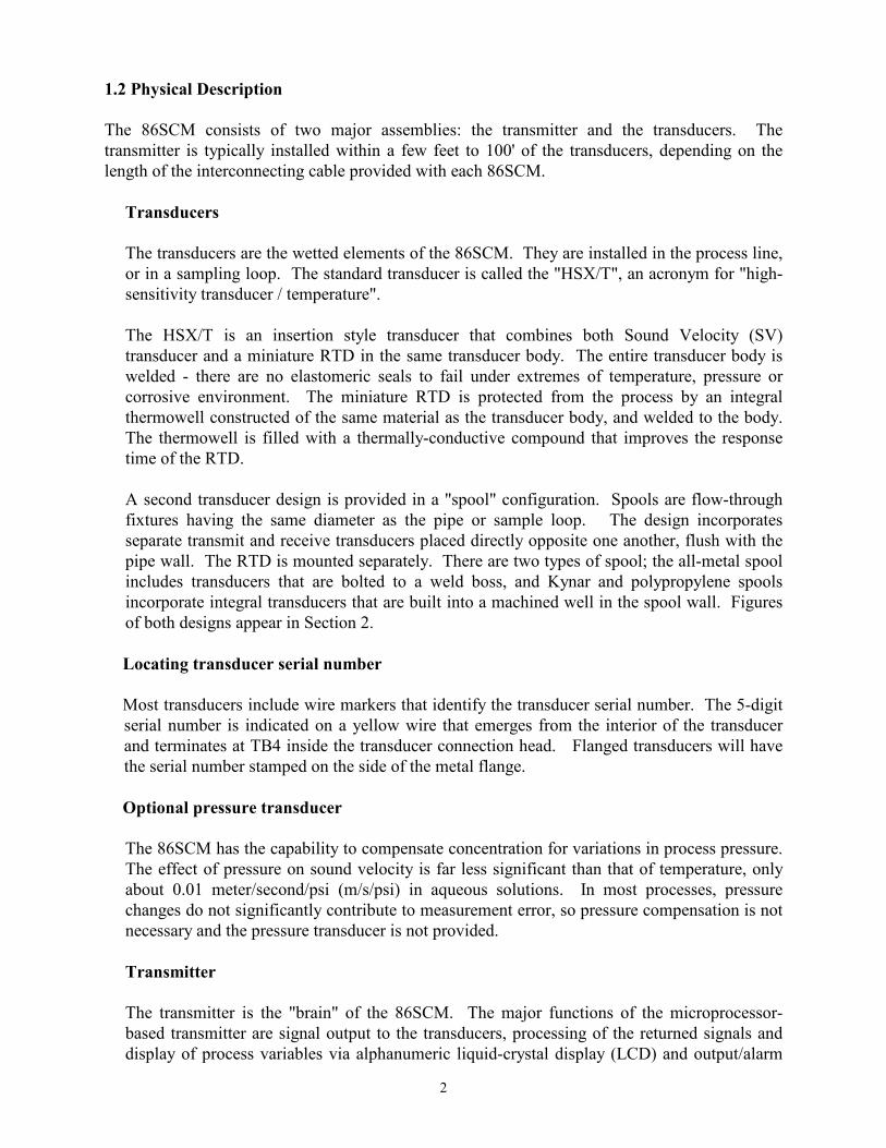


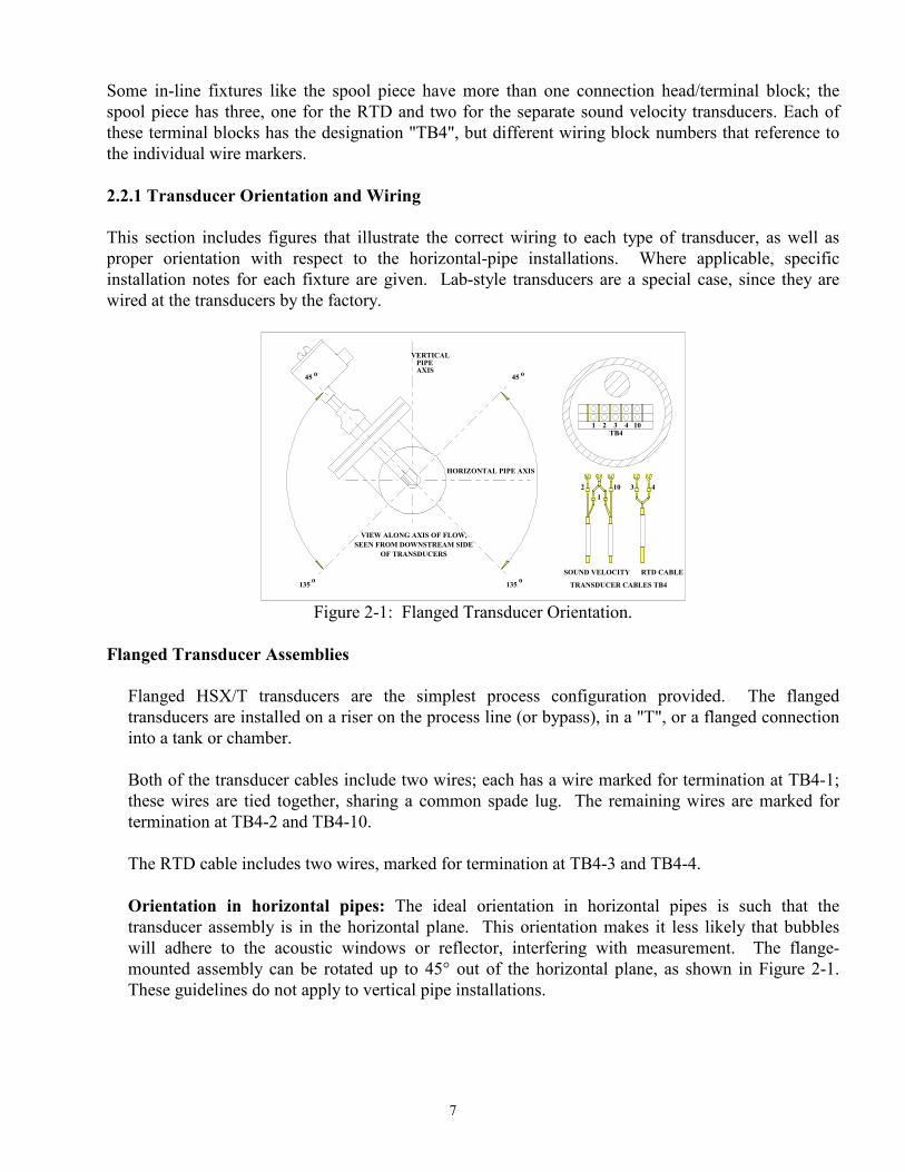

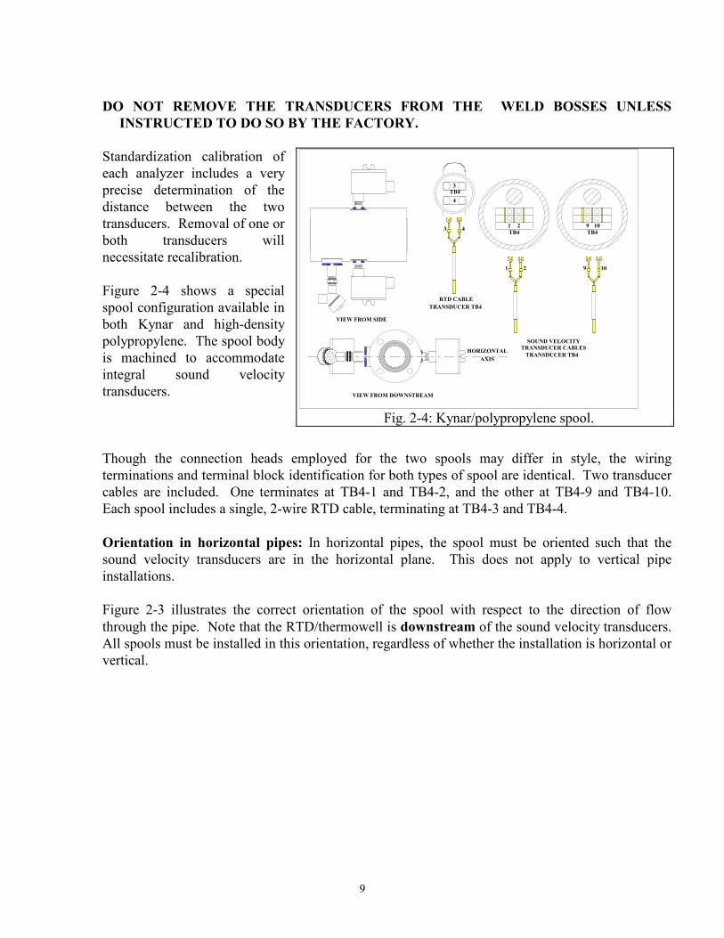

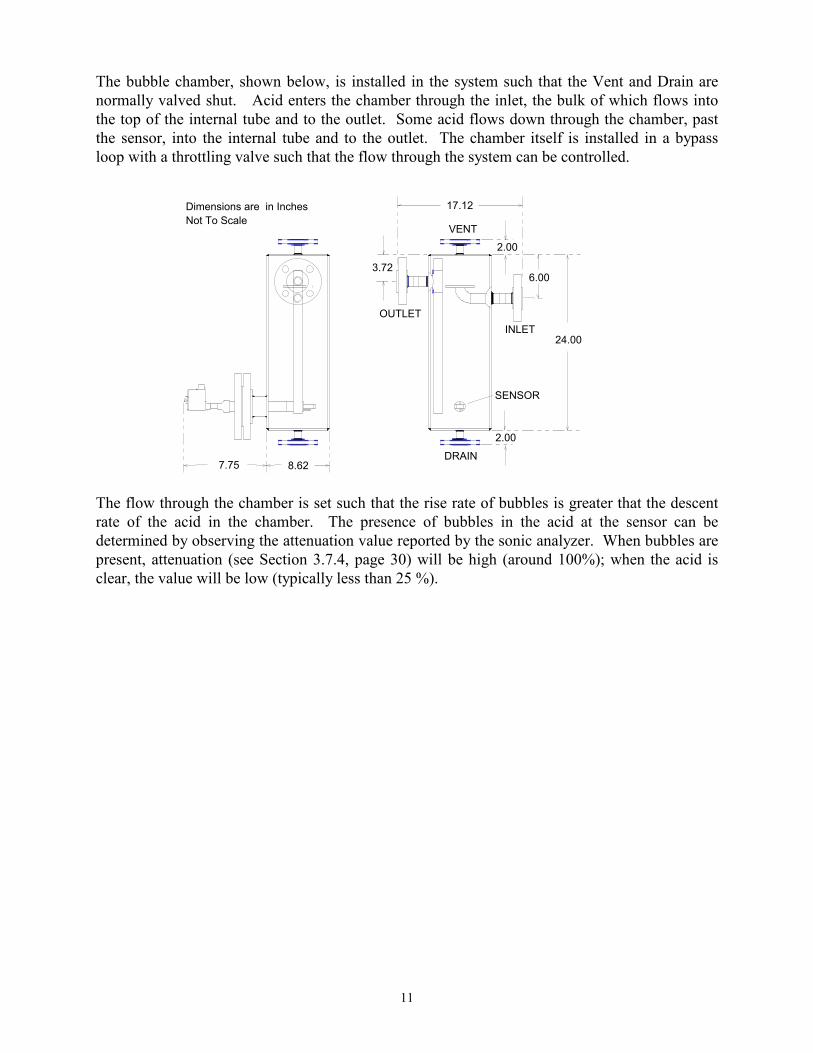

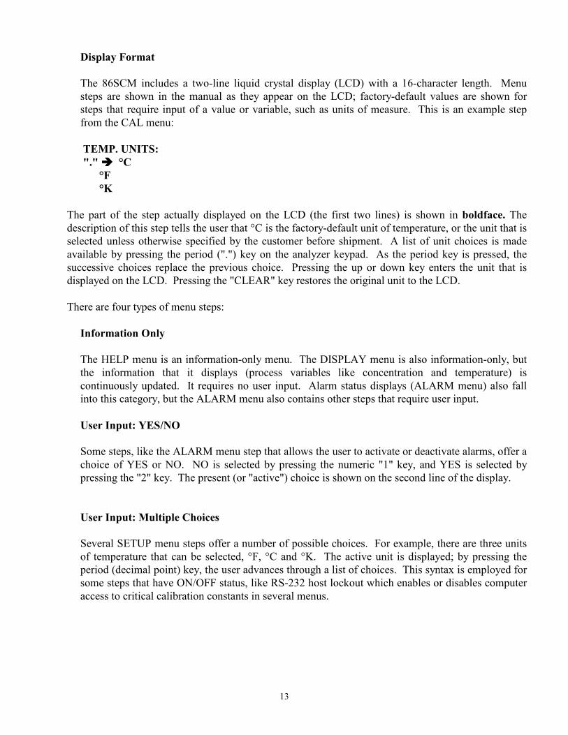


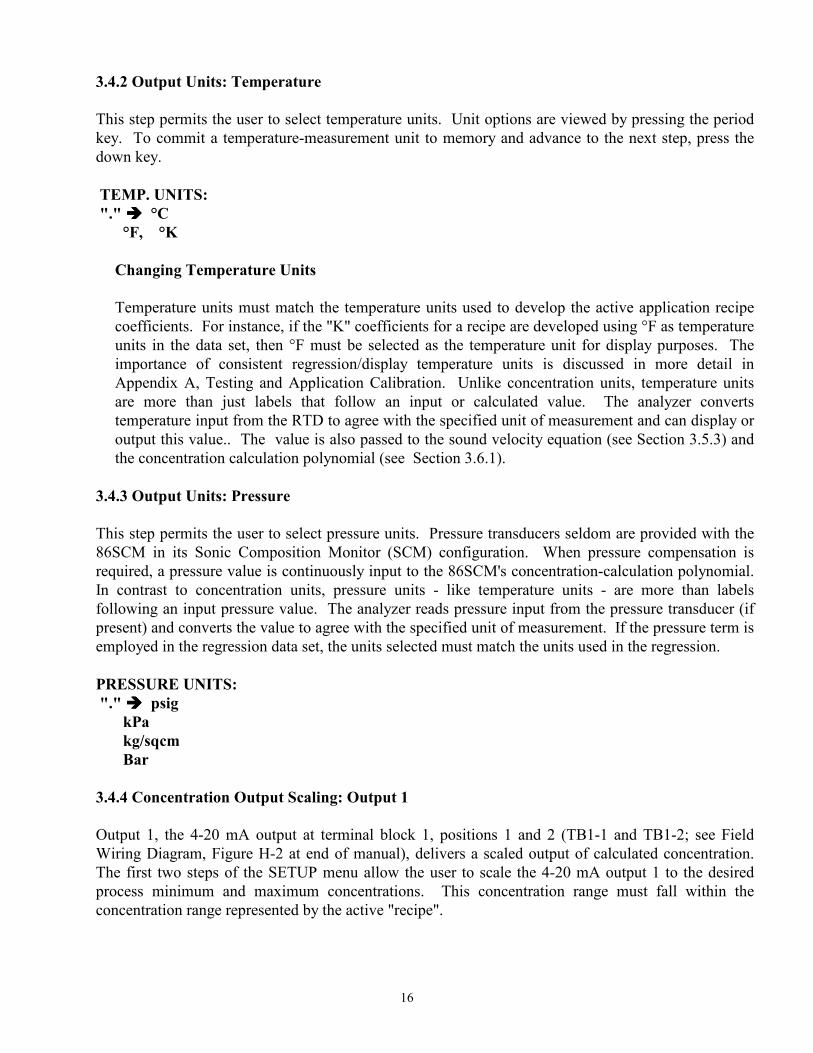


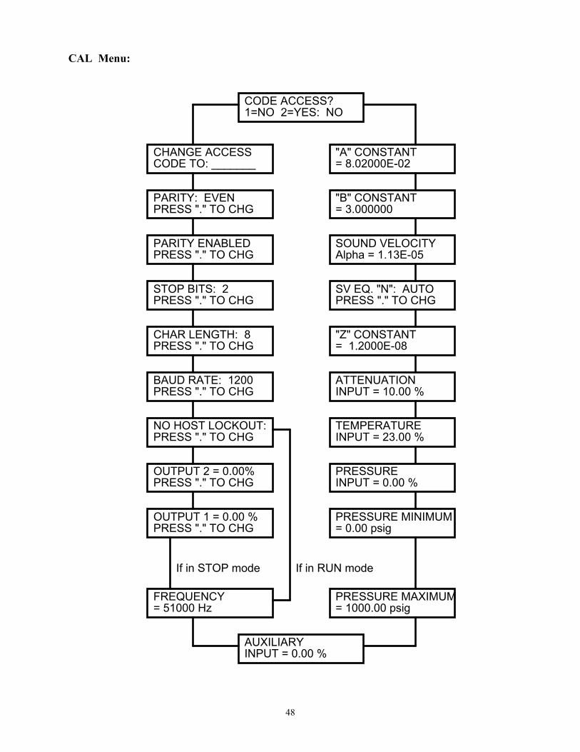
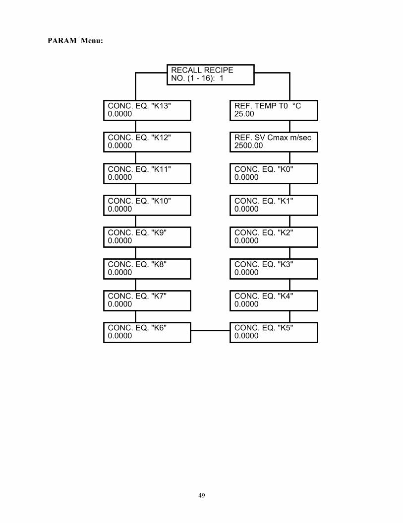
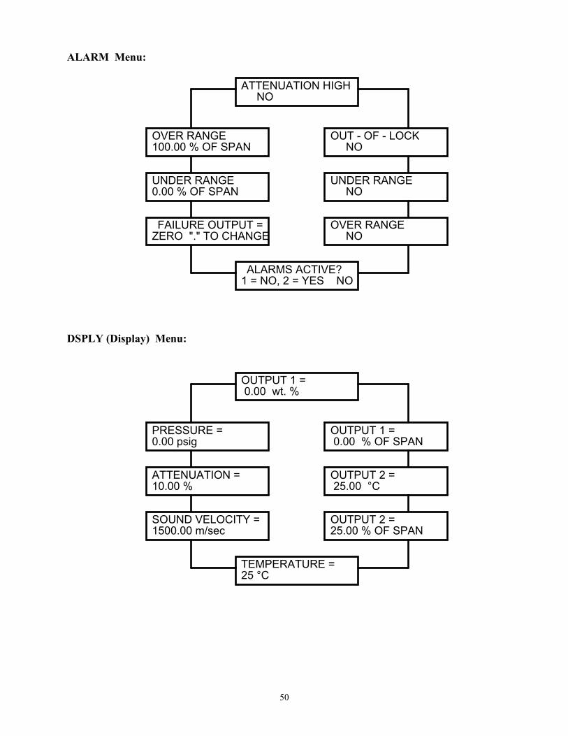
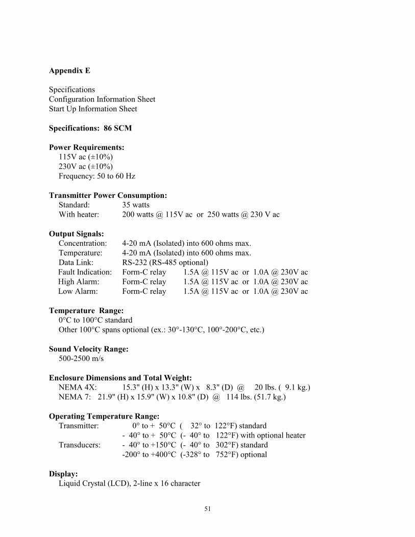

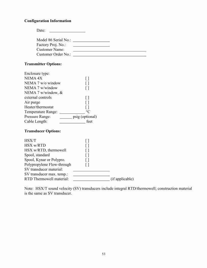


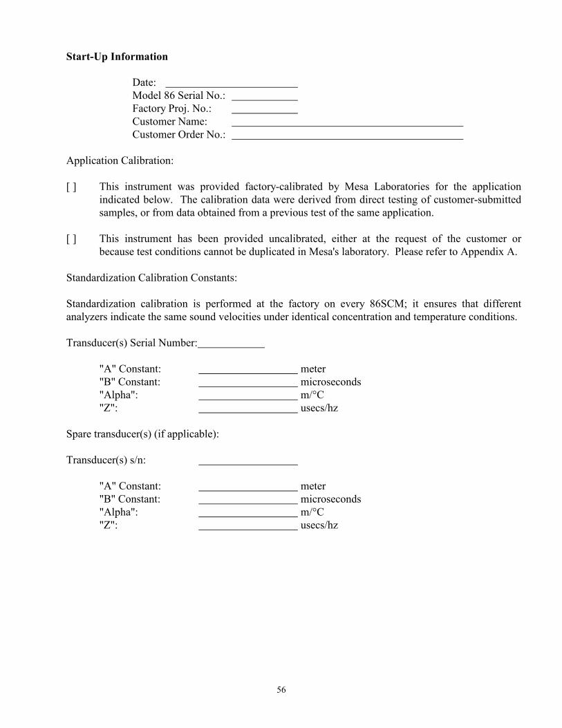
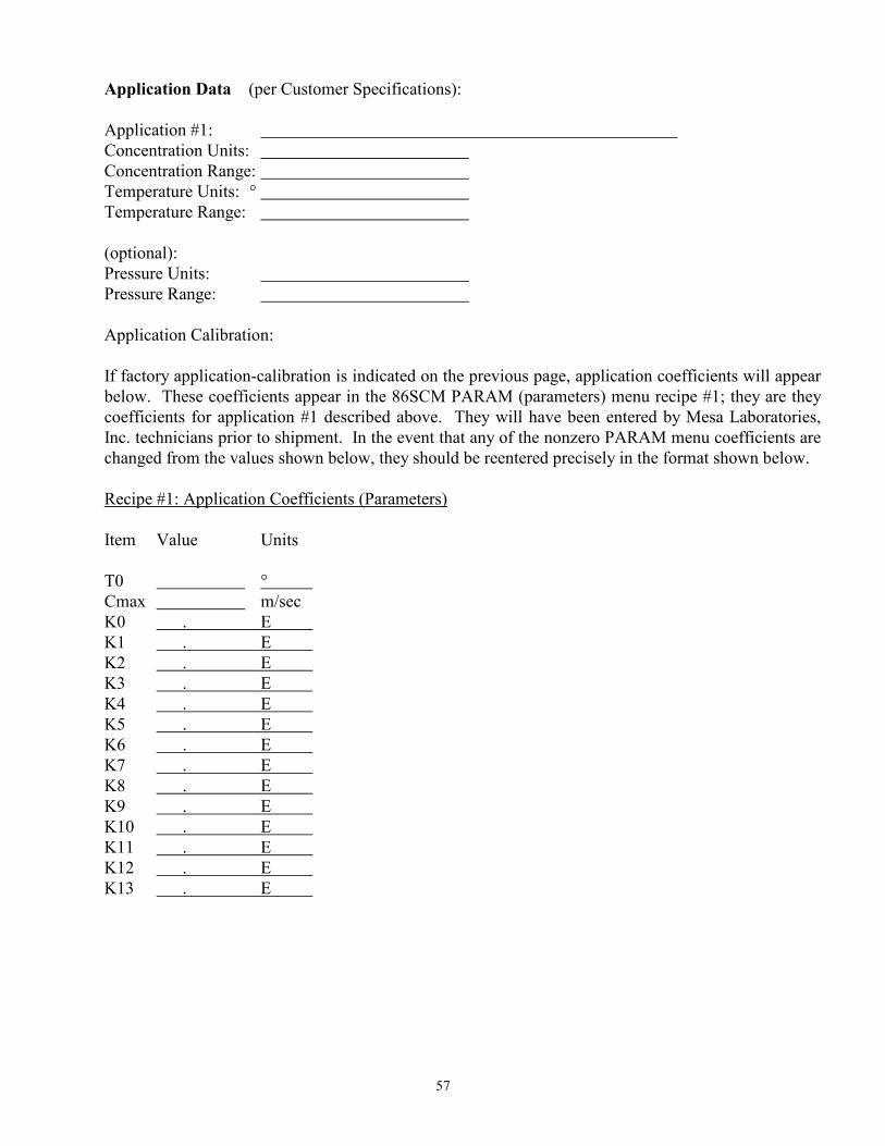
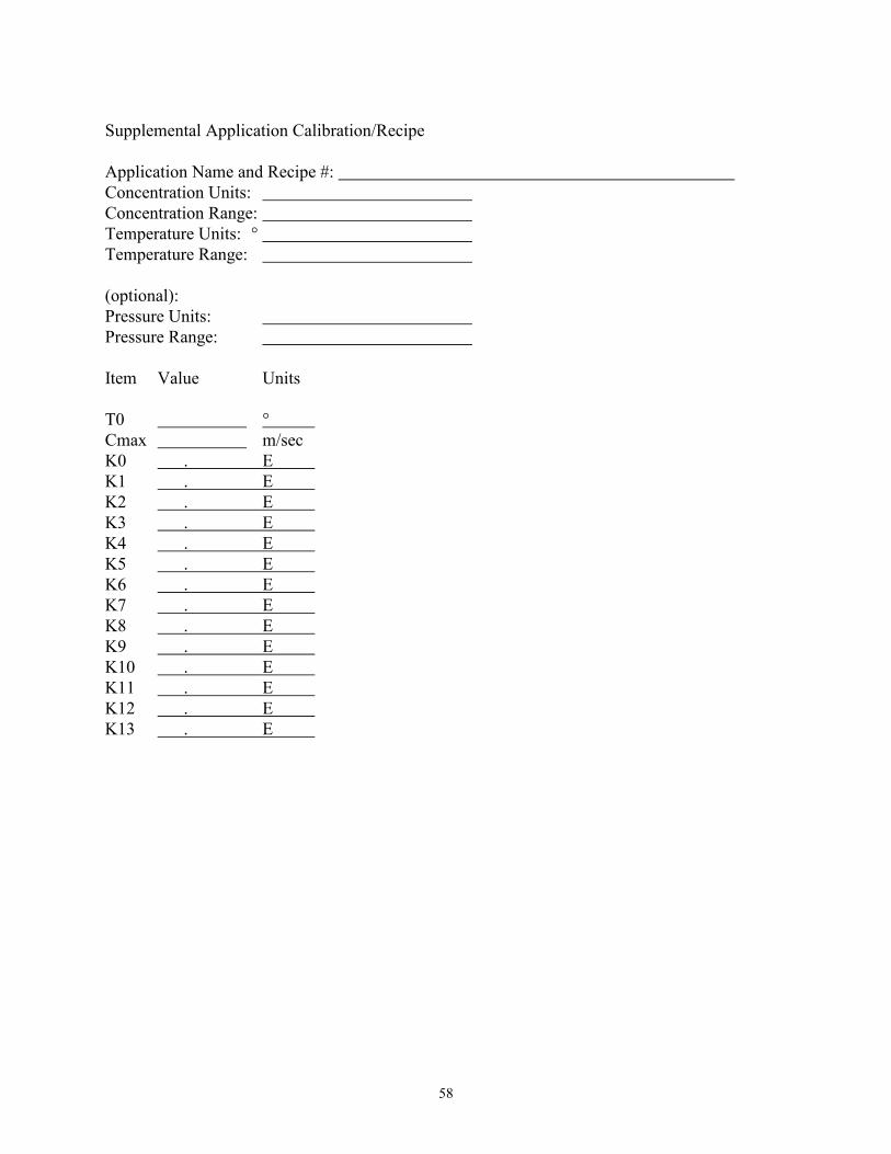

![Manual de Concentracion[1]](https://static.documents.pub/doc/80x56/577d2a871a28ab4e1ea96b45/manual-de-concentracion1.jpg)


