1.0 Overview........................................................................................................... 21.1 The Micro TOL Series ......................................................................... 21.2 Unpacking and Inspection of the Instrument and Accessories ............. 31.3 The Display .......................................................................................... 31.4 The Touch Pad ...................................................................................... 41.5 Vapor Purge........................................................................................... 4
3.0 Installation and Commissioning ....................................................................... 53.1 Mounting and Site Selection ................................................................. 53.2 Plumbing ............................................................................................. 6
7.1 Selecting the Output (O/P) ................................................................. 167.2 Setting the 4-20 mA ............................................................................ 167.3 Configuring the Error Level................................................................ 177.4 Configuring the RS-485 Port .............................................................. 187.5 Configuring the Alarms....................................................................... 18
9.0 Troubleshooting & Maintenance .................................................................... 299.1 Micro TOL Fault Detection................................................................. 299.2 System Fail Message .......................................................................... 299.3 Diagnostic Chart ................................................................................. 309.4 Technical and Customer Assistance ................................................... 30
10.0 Routine Maintenance....................................................................................... 3110.1 Cleaning the Flow Through Cuvette .................................................. 3110.2 Replacing or Installing the Desiccant Pouch ...................................... 3110.3 Replacing the Source Lamp ............................................................... 31
11.0 Accessories and Replacement Parts List ........................................................ 32
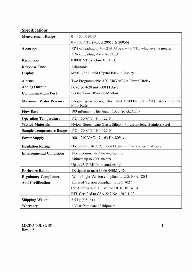
1.0 OverviewThe MICRO TOL process turbidimeter allows for the measurement of the turbidity of
process water on-line. The White Light MICRO TOL has been designed to meet thedesign criteria specified by the US EPA 180.1 on turbidity measurement. The infraredMICRO TOL was designed to meet the design criteria specified in ISO 7027 and DIN27027 for the measurement of the turbidity of a sample. Both models have long life lamps.
Some models have ultrasonic cleaning. Refer to section 8.2 for more information.
A pressure regulator on the incoming line is a standard on all Micro TOL instruments andwill reduce pressures up to 1380kPa (200 PSI) down to (104kPa) 15 PSI.
1.1 The Micro TOL Series
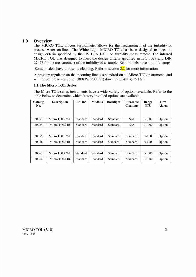
The Micro TOL series instruments have a wide variety of options available. Refer to the
table below to determine which factory installed options are available.Catalog
No.
Description RS-485 Modbus Backlight Ultrasonic
Cleaning
Range
NTU
Flow
Alarm
20053 Micro TOL2 WL Standard Standard Standard N/A 0-1000 Option
20054 Micro TOL2 IR Standard Standard Standard N/A 0-1000 Option
20055 Micro TOL3 WL Standard Standard Standard Standard 0-100 Option
20056 Micro TOL3 IR Standard Standard Standard Standard 0-100 Option
20063 Micro TOL4 WL Standard Standard Standard Standard 0-1000 Option
20064 Micro TOL4 IR Standard Standard Standard Standard 0-1000 Option
1.2 Unpacking and Inspection of the Instrument and AccessoriesThe table below indicates the items in the turbidimeter shipment.
Item Quantity
MICRO TOL Turbidimeter c/w Field Terminal Box & Flow Through
Assembly1
Instruction Manual 1
Desiccant Pack 1
Cuvette (Single Pack) 1
Tubing Kit: 1-shutoff clamp1-backpressure valve
2-connecting tubing with fittings for flow through assembly
1-drain vent screw (used in pressurized systems)
1
Remove the instrument from the packing carton. Carefully inspect all items to ensure thatno visible damage has occurred during shipment. If the items received do not match theorder, please immediately contact the local distributor or the HF scientific CustomerService department.
Note: The spare cuvette part# 50033 is not included for models 20055, 20056 20063 & 20064.
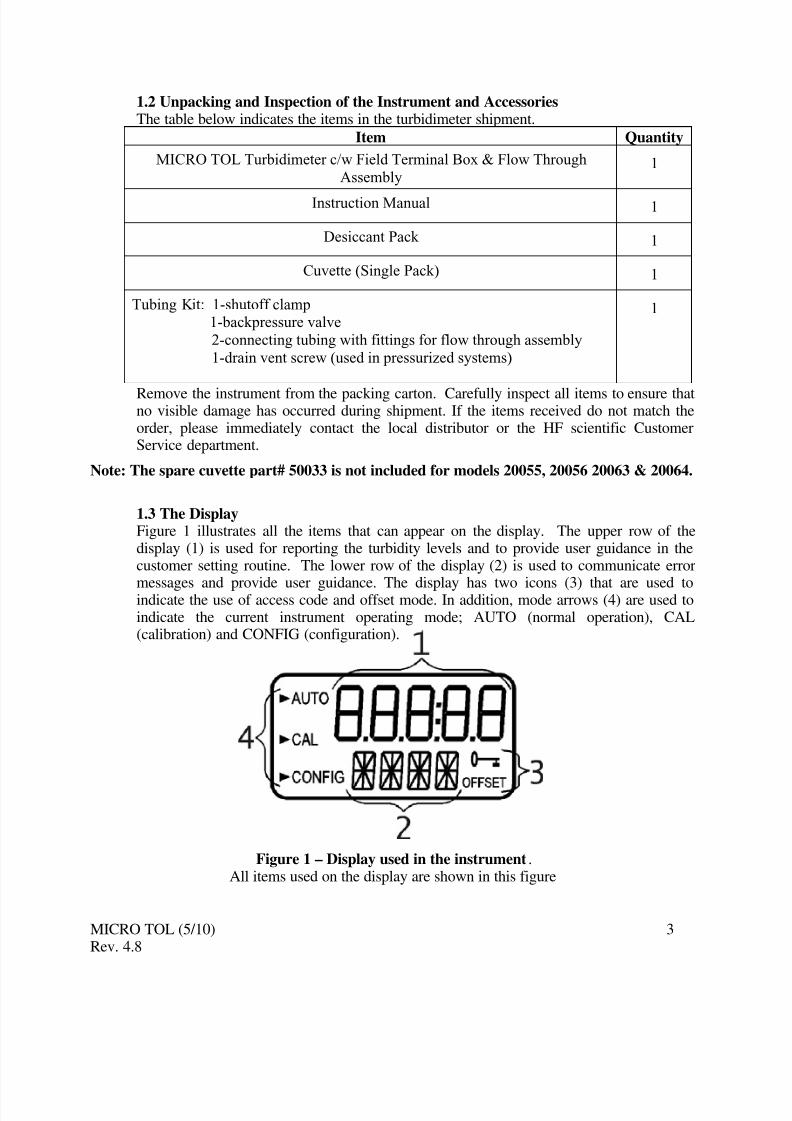
1.3 The DisplayFigure 1 illustrates all the items that can appear on the display. The upper row of thedisplay (1) is used for reporting the turbidity levels and to provide user guidance in thecustomer setting routine. The lower row of the display (2) is used to communicate error
messages and provide user guidance. The display has two icons (3) that are used toindicate the use of access code and offset mode. In addition, mode arrows (4) are used toindicate the current instrument operating mode; AUTO (normal operation), CAL(calibration) and CONFIG (configuration).
Figure 1 – Display used in the instrument.All items used on the display are shown in this figure
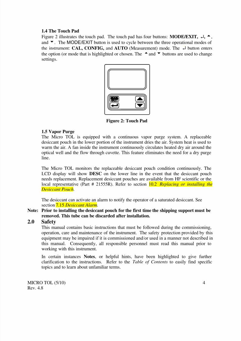
Figure 2 illustrates the touch pad. The touch pad has four buttons: MODE/EXIT, ↵,t,
andu. The MODE/EXIT button is used to cycle between the three operational modes of
the instrument: CAL, CONFIG, and AUTO (Measurement) mode. The ↵ button enters
the option (or mode that is highlighted or chosen. The tandu buttons are used to change
settings.
Figure 2: Touch Pad
1.5 Vapor PurgeThe Micro TOL is equipped with a continuous vapor purge system. A replaceabledesiccant pouch in the lower portion of the instrument dries the air. System heat is used towarm the air. A fan inside the instrument continuously circulates heated dry air around theoptical well and the flow through cuvette. This feature eliminates the need for a dry purgeline.
The Micro TOL monitors the replaceable desiccant pouch condition continuously. The
LCD display will show DESC on the lower line in the event that the desiccant pouch
needs replacement. Replacement desiccant pouches are available from HF scientific or thelocal representative (Part # 21555R). Refer to section 10.2 Replacing or installing the Desiccant Pouch.
The desiccant can activate an alarm to notify the operator of a saturated desiccant. Seesection 7.15 Desiccant Alarm.
Note: Prior to installing the desiccant pouch for the first time the shipping support must be
removed. This tube can be discarded after installation.
2.0 SafetyThis manual contains basic instructions that must be followed during the commissioning,operation, care and maintenance of the instrument. The safety protection provided by this
equipment may be impaired if it is commissioned and/or used in a manner not described inthis manual. Consequently, all responsible personnel must read this manual prior toworking with this instrument.
In certain instances Notes, or helpful hints, have been highlighted to give furtherclarification to the instructions. Refer to the Table of Contents to easily find specifictopics and to learn about unfamiliar terms.
3.0 Installation and CommissioningPrior to use for the first time, the supplied desiccant pouch will need to be installed. Referto section 10.2 Replacing or Installing the Desiccant Pouch.
3.1 Mounting & Site Selection
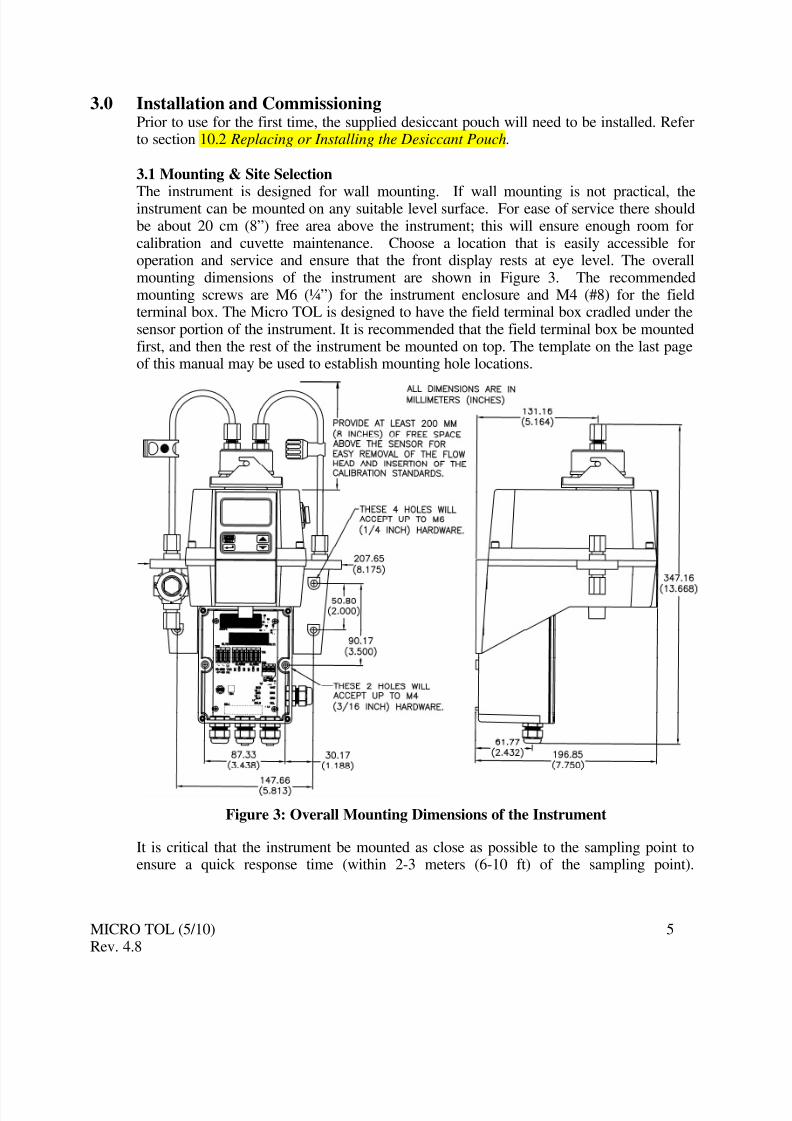
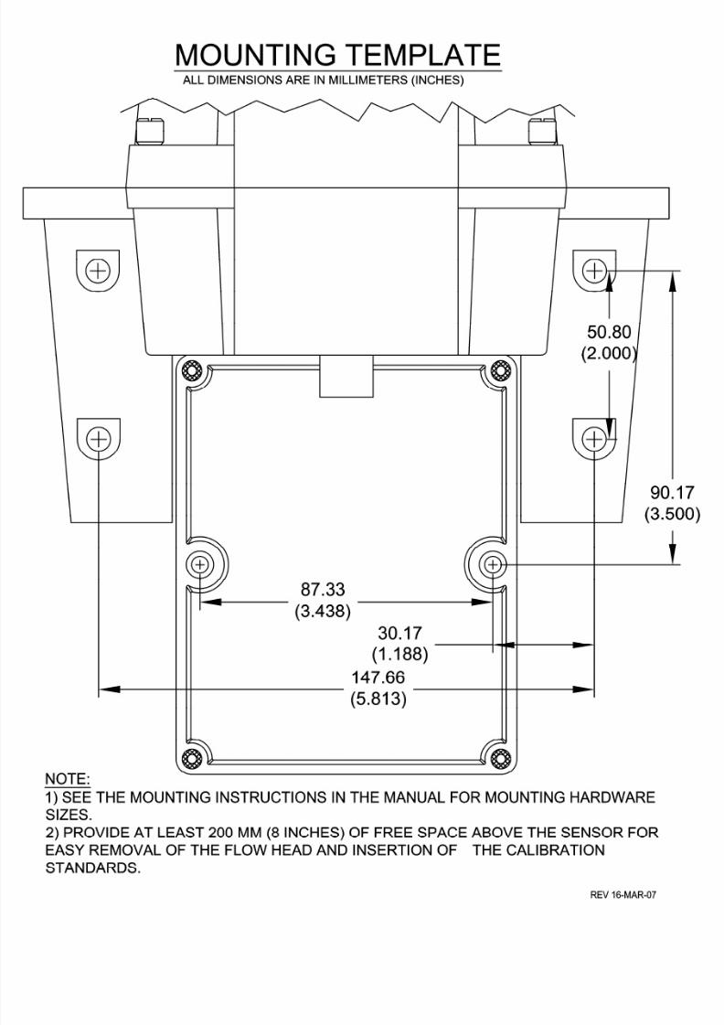
The instrument is designed for wall mounting. If wall mounting is not practical, theinstrument can be mounted on any suitable level surface. For ease of service there shouldbe about 20 cm (8”) free area above the instrument; this will ensure enough room forcalibration and cuvette maintenance. Choose a location that is easily accessible foroperation and service and ensure that the front display rests at eye level. The overallmounting dimensions of the instrument are shown in Figure 3. The recommendedmounting screws are M6 (¼”) for the instrument enclosure and M4 (#8) for the fieldterminal box. The Micro TOL is designed to have the field terminal box cradled under thesensor portion of the instrument. It is recommended that the field terminal box be mountedfirst, and then the rest of the instrument be mounted on top. The template on the last pageof this manual may be used to establish mounting hole locations.
Figure 3: Overall Mounting Dimensions of the Instrument
It is critical that the instrument be mounted as close as possible to the sampling point toensure a quick response time (within 2-3 meters (6-10 ft) of the sampling point).
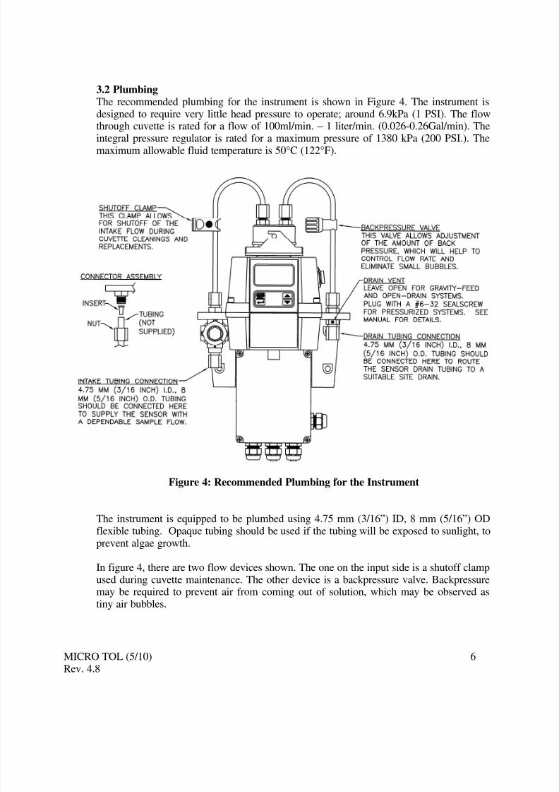
3.2 PlumbingThe recommended plumbing for the instrument is shown in Figure 4. The instrument isdesigned to require very little head pressure to operate; around 6.9kPa (1 PSI). The flowthrough cuvette is rated for a flow of 100ml/min. – 1 liter/min. (0.026-0.26Gal/min). The
integral pressure regulator is rated for a maximum pressure of 1380 kPa (200 PSI.). Themaximum allowable fluid temperature is 50°C (122°F).
Figure 4: Recommended Plumbing for the Instrument
The instrument is equipped to be plumbed using 4.75 mm (3/16”) ID, 8 mm (5/16”) ODflexible tubing. Opaque tubing should be used if the tubing will be exposed to sunlight, toprevent algae growth.
In figure 4, there are two flow devices shown. The one on the input side is a shutoff clampused during cuvette maintenance. The other device is a backpressure valve. Backpressuremay be required to prevent air from coming out of solution, which may be observed astiny air bubbles.
3.2.1 Drain Vent: The Micro TOL has been fitted with a drain vent in the “OUT”bulkhead fitting. This fitting allows for atmospheric equalization, thus helping to alleviatebubble formation in the cuvette. Refer to Figure 4.
Upon initial flow minor leakage may occur through the drain vent. This will subside oncenormal flow is established.
For some high pressure systems, where the vent hole continuously leaks, a 6:32 seal screwis provided which should be inserted into the vent hole and tightened.
The sensor drain tubing MUST be routed to a suitable drain. DO NOT reintroduce thedrain sample to the process stream. This is due to the fact that the wetted materials are notFDA approved. See below for more information.
3.2.2 Wetted Materials: HF scientific accepts no responsibility for damage caused bythe introduction of vapors, fluids or other materials into the instrument process streamwhich is not compatible with the instrument’s wetted materials. A list of the wetted
materials can be found in the specifications on page 1 of this manual.
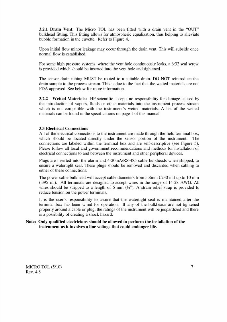
3.3 Electrical ConnectionsAll of the electrical connections to the instrument are made through the field terminal box,which should be located directly under the sensor portion of the instrument. Theconnections are labeled within the terminal box and are self-descriptive (see Figure 5).Please follow all local and government recommendations and methods for installation of electrical connections to and between the instrument and other peripheral devices.
Plugs are inserted into the alarm and 4-20mA/RS-485 cable bulkheads when shipped, toensure a watertight seal. These plugs should be removed and discarded when cabling to
either of these connections.
The power cable bulkhead will accept cable diameters from 5.8mm (.230 in.) up to 10 mm(.395 in.). All terminals are designed to accept wires in the range of 14-28 AWG. Allwires should be stripped to a length of 6 mm (¼”). A strain relief strap is provided toreduce tension on the power terminals.
It is the user’s responsibility to assure that the watertight seal is maintained after theterminal box has been wired for operation. If any of the bulkheads are not tightenedproperly around a cable or plug, the ratings of the instrument will be jeopardized and thereis a possibility of creating a shock hazard.
Note: Only qualified electricians should be allowed to perform the installation of the
instrument as it involves a line voltage that could endanger life.
Figure 5: Electrical Connections for the Instrument
3.3.1 Power: The instrument is equipped with a 100-240 VAC, 47-63 Hz switching powersupply; please verify that the line voltage falls within these specifications. It isrecommended that a circuit breaker be placed prior to the power connection to allow for
service. While making connections, refer to Figure 5. The Micro TOL is not supplied
with a power cord.
3.3.2 RS-485: The RS-485 half-duplex (2-wire) digital interface operates with differentiallevels that are not susceptible to electrical interferences. This is why cable lengths up to3000 ft can be implemented. The last device on each bus may require terminating with a120-ohm resistor to eliminate signal reflection on the line. Do not run RS-485 cables inthe same conduit as power.
To prevent damage to the instrument, ensure that power is disconnected prior to making
connections. For ease of connecting, remove the plug in terminal block. Connections arelabeled beneath this termination.
3.3.3 Relays: The Alarm 1 and Alarm 2 relays are mechanical relays rated at 240 VAC2A. Please note that the relays are labeled NO (Normally Open), NC (Normally Closed)and C (Common). As these alarms are configured fail-safe, the normal condition is withpower applied to the Micro TOL and in a non-alarm condition. Operation of these alarmsis covered in section 7.5 Configuring the Alarms.
3.3.4 4-20 mA: The 4-20 mA output is driven by a 15 VDC power source and can driverecorder loads up to 600 ohms. This 4-20 mA output is isolated from line power and earthground. Do not run 4-20 mA cables in the same conduit as power. Operation of this outputis covered in section 7.2 Setting the 4-20 mA. Optional transformer isolated outputs areavailable as a factory installed option (Catalog No. 21045A).
Note: The installation of the 4-20 mA isolator will render the RS-485 non-operational.
Ensure each instrument is not powered when connecting the 4-20 mA. To prevent damageto the instrument, ensure that power is disconnected prior to making connections. For easeof connecting, remove the plug in terminal block. Polarities of the connections are labeledbeneath this termination.
This process turbidimeter allows for the measurement of the turbidity of process water on-
line. The turbidity of the process water is usually reported in Nephelometric Turbidity
Units (NTU), but may be reported in Formazin Nephelometric Units (FNU). Readingsabove 1000 NTU (100 for models 20055 & 20056) are outside the range of this
instrument. Readings above 1100 NTU (110 for models 20055 & 20056) will cause thedisplay to flash indicating an over range condition.
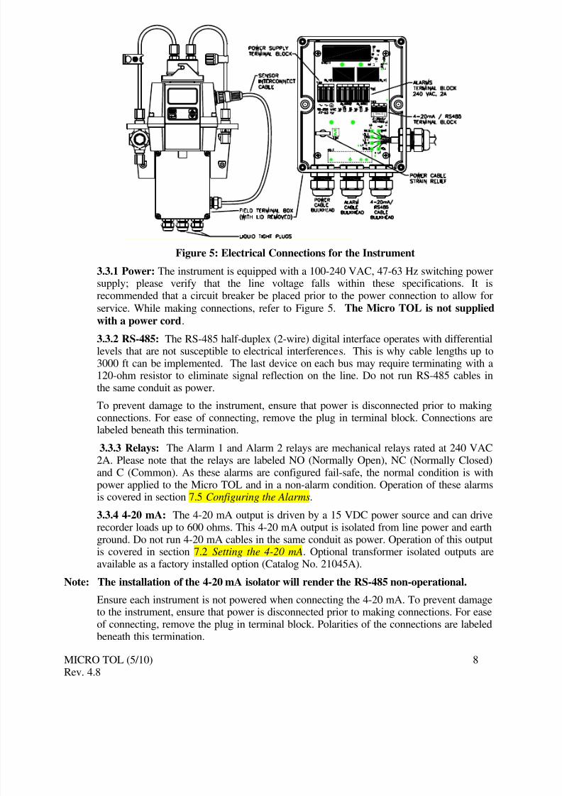
During normal operation, the instrument will have the arrow beside AUTO highlightedwith the current scale displayed on the lower row of the display and the measured readingon the upper row of the display (see illustration below).
4.1 Routine MeasurementThe following steps describe how to measure the turbidity of a sample using thisinstrument:
1. Apply power to the instrument and allow the unit to warm up (typically 45 minutes – 1hour on initial commissioning).
2. When a continuous process stream is flowing through the instrument, the instrumentwill display the measured turbidity level of the sample by displaying it on the LCDscreen. In addition, the equivalent signal is provided on the analog (4-20 mA) output,or the digital output, depending on the options selected.
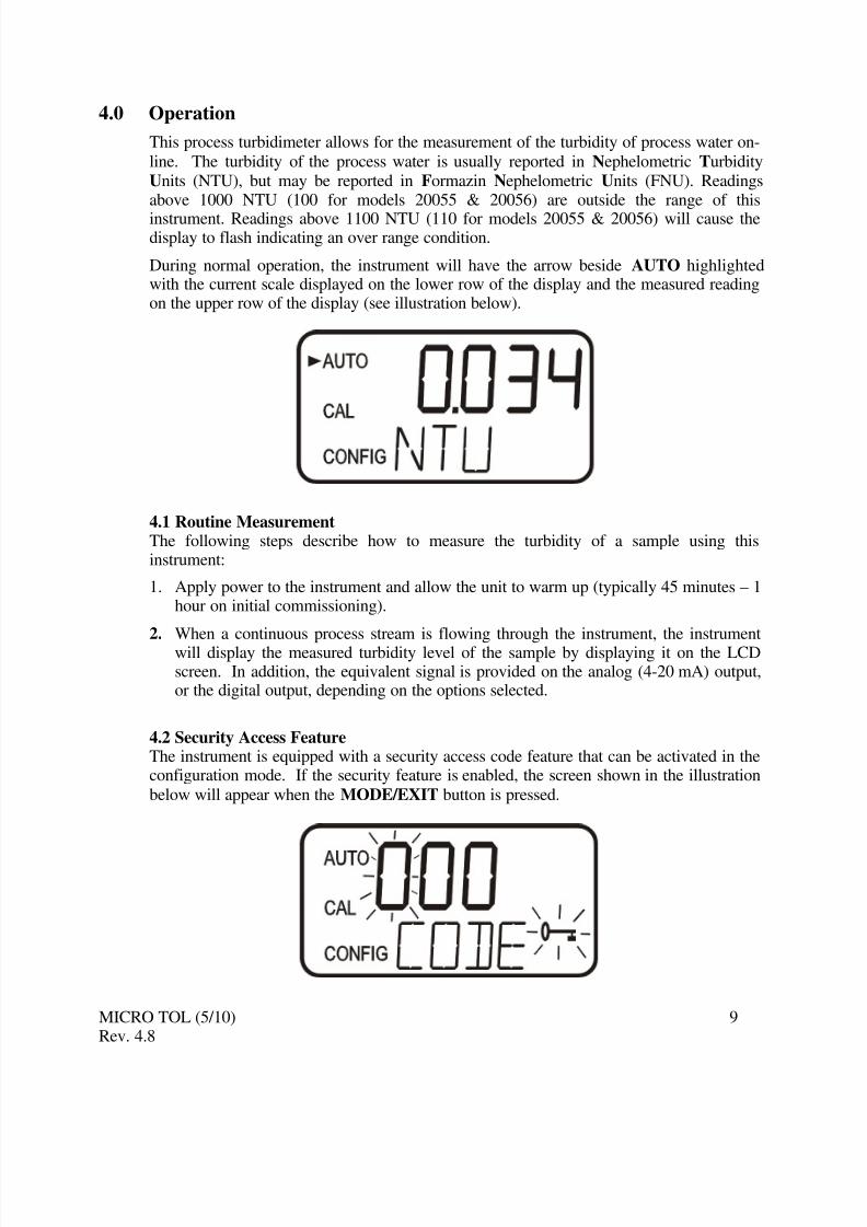
4.2 Security Access FeatureThe instrument is equipped with a security access code feature that can be activated in theconfiguration mode. If the security feature is enabled, the screen shown in the illustration
below will appear when the MODE/EXIT button is pressed.
The security code (333) must be entered to gain access to CAL or CONFIG menus.Notice that the first number in the code is flashing; the flashing indicates that this is the
number to be changed. Use thetor u arrows to select the first of the three numbers in
the code and then press the ↵ button to accept the first number of the code. Now enter the
second number in the code. Proceed as with the first number followed by ↵. Then repeat
the process for the third number in the access code, and finish with the ↵ button.
If the valid access code has been selected, the instrument will be directed to the calibration
mode. If the wrong access code is selected, the instrument will return to the AUTO mode.Refer to section 7.7 Enabling the Security Access for more information.
The instrument was calibrated and tested prior to leaving the factory. Therefore, it ispossible to use the instrument directly out of the box. Under normal conditions, re-calibration is recommended at least once every three months
1.
Relay contacts will change to the alarm state while the instrument is in the calibrationand/or in the configuration mode. While in the calibration mode, the instrument has a
time-out feature that automatically returns the system operation to the AUTO mode after afifteen (15) minute period of inactivity.
5.1 Calibration StandardsIf the Micro TOL will be used over the entire range of .02 to 1000 NTU a completecalibration as described below will be required. If instrument accuracy is only requiredbelow 10 NTU, such as potable water, a calibration may be performed using only a 10
NTU and a 0.02 NTU standard. To calibrate starting at the 10 NTU, press theubutton tobypass the 1000 NTU and proceed to Section 5.2 Calibration Procedures, step 5.
We recommend that the following materials be used during calibration to achieve the full-scale accuracy stated in this manual:
1. 0.02 NTU ProCal Calibration Standard available from HF scientific
2. 10.0 NTU ProCal Calibration Standard available from HF scientific
3. 1000 NTU ProCal Calibration Standard available from HF scientific
It is well known that diluted Formazin is unstable. If Formazin is used to calibrate theinstrument, ensure that a fresh stock suspension of Formazin is used to achieve theaccuracy quoted for the instrument. A Formazin Stock Solution Kit is available from HF
(refer to section 11.0 Accessories and Replacement Parts List ) are more stable thanFormazin and have a minimum shelf life of 12 months. Prior to recalibration, review theexpiration dates, to ensure that the standards have not expired.
Note: The range of Models 20055 & 20056 is .02 to 100 NTU. For calibrating these models
replace the 1000 NTU standard with a 100 NTU standard.
1 The EPA recommends that on-line turbidimeters be calibrated with a primary standard at least once every three
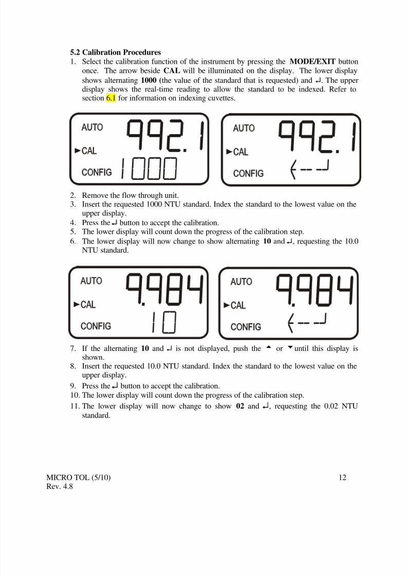
5.2 Calibration Procedures1. Select the calibration function of the instrument by pressing the MODE/EXIT button
once. The arrow beside CAL will be illuminated on the display. The lower display
shows alternating 1000 (the value of the standard that is requested) and ↵. The upperdisplay shows the real-time reading to allow the standard to be indexed. Refer to
section 6.1 for information on indexing cuvettes.
2. Remove the flow through unit.
3. Insert the requested 1000 NTU standard. Index the standard to the lowest value on theupper display.
4. Press the ↵ button to accept the calibration.5. The lower display will count down the progress of the calibration step.
6. The lower display will now change to show alternating 10 and ↵, requesting the 10.0NTU standard.
7. If the alternating 10 and ↵ is not displayed, push the t or uuntil this display isshown.
8. Insert the requested 10.0 NTU standard. Index the standard to the lowest value on theupper display.
9. Press the ↵ button to accept the calibration.
10. The lower display will count down the progress of the calibration step.
11. The lower display will now change to show 02 and ↵, requesting the 0.02 NTUstandard.
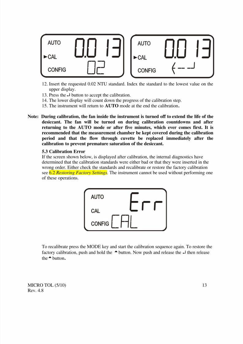
12. Insert the requested 0.02 NTU standard. Index the standard to the lowest value on theupper display.
13. Press the ↵ button to accept the calibration.14. The lower display will count down the progress of the calibration step.
15. The instrument will return to AUTO mode at the end the calibration.
Note: During calibration, the fan inside the instrument is turned off to extend the life of the
desiccant. The fan will be turned on during calibration countdowns and afterreturning to the AUTO mode or after five minutes, which ever comes first. It isrecommended that the measurement chamber be kept covered during the calibration
period and that the flow through cuvette be replaced immediately after thecalibration to prevent premature saturation of the desiccant.
5.3 Calibration Error If the screen shown below, is displayed after calibration, the internal diagnostics havedetermined that the calibration standards were either bad or that they were inserted in thewrong order. Either check the standards and recalibrate or restore the factory calibrationsee 6.2 Restoring Factory Settings. The instrument cannot be used without performing oneof these operations.
To recalibrate press the MODE key and start the calibration sequence again. To restore the
factory calibration, push and hold thetbutton. Now push and release the ↵ then release
6.0 Instrument OffsetIn certain instances, it may be desirable to use an offset factor to calibrate the instrumentrather than performing a physical calibration of the instrument (as described in section5.2). This procedure is not recommended in lieu of regular instrument calibration but itcan be used in situations where the number of instruments used makes regular calibration
prohibitive. This calibration technique will make the instrument accurate only at turbiditylevels in the immediate vicinity of the grab sample and not in the full range of theinstrument. Note that the OFFSET icon will be illuminated whenever an offset used. Themaximum offset is ± 1.00 NTU. If instrument variation is greater than 1 NTU a full
calibration is recommended.
The procedures are as follows:1. Collect a grab sample of the process water that is being monitored by the instrument
and record the turbidity reported by the instrument.2. Take the grab sample and measure its turbidity using a laboratory turbidimeter
(contact the HF scientific customer services department for examples of laboratoryturbidimeters).
3. Compare the turbidity reported by the instrument to that obtained in the laboratory. If the readings are very close, then no offset adjustment or calibration is required and theprocedure may be stopped at this step. However, if the readings are substantiallydifferent (but less that 1 NTU), continue on in this procedure to utilize the offsetoption to improve the turbidity reading of the instrument so that it will agree with thelaboratory reading between calibrations.
4. Select the offset function of the instrument by pressing the MODE/EXIT button until
the arrow beside CONFIG is illuminated on the display. Refer to the following screen.
5. Push the ↵ button until OFST is displayed on the lower row.
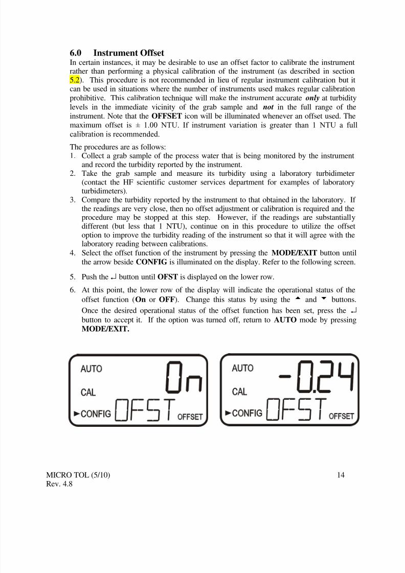
6. At this point, the lower row of the display will indicate the operational status of the
offset function (On or OFF). Change this status by using thet
andu
buttons.Once the desired operational status of the offset function has been set, press the ↵
button to accept it. If the option was turned off, return to AUTO mode by pressing
7. If the option was turned On, the upper row will display the offset required. This willadd or subtract the value of the offset to the measured NTU value. As an example if the Micro TOL measures the process at 0.16 NTU but the laboratory instrument readthe sample at 0.12 NTU, adding an offset of –0.04 would result in the Micro TOL
displaying 0.12 NTU.
Select the desired offset level using thet andu buttons. Once the desired level has
been set, press the ↵ button to accept it.8. This completes the offset configuration.
9. At this point, the instrument will continue through the configuration (CONFIG) mode
of the instrument or press MODE/EXIT to return to the AUTO mode.
6.1 Indexing Calibration CuvettesTo achieve the greatest accuracy, and account for normal scratches and aberrations incuvette glass when calibrating, HF scientific recommends indexing the cuvettes.
Standards and standard kits purchased from HF scientific are supplied with indexing rings.
The following steps allow repeatable indexing of calibration standards:
1. With the instrument in AUTO mode insert the standard.
2. Slowly rotate the standard, inside the optical well, one complete revolution (360º).While rotating the standard slowly, observe the measured turbidity and locate theposition of the cuvette having the lowest reading.
3. With the calibration standard positioned at the location having the lowest turbidityreading, install the Indexing Ring over the cap on the standard so that the pointer of the Indexing Ring faces directly forward.
When using the standards in future, always insert the standard so that the pointer of the
indexing ring faces forward. Slowly rotate the standard back and forth about 5° to find thelowest point. The standard is now indexed and ready for use.
6.2 Restoring Factory SettingsIf the instrument is unable to perform a calibration due to a low lamp output or acalibration using the wrong standards, the instrument will display CAL on the lower row
of the display and Err on the upper row. The operator has two choices to correct thisproblem. If the operator can determine whether a poor calibration or a low lamp causedthe problem, he/she can remedy the problem and recalibrate. If all else fails, the operatormay restore the factory calibration and configuration settings by performing the following
operation. Push and hold the tbutton. Now push and release the ↵ then release
thetbutton. Factory calibration and factory configuration have now been restored.
Note: Restoring the factory settings allows the use of the Micro TOL with reduced accuracy.The original problem still exists and must be determined and corrected before
accurate operation of the Micro TOL will be resumed.
The instrument has been designed to provide the ability to customize the instrumentaccording to needs at any time during normal operation. This mode has been split intosub-menus to facilitate instrument configuration. This section describes how to use eachof the sub-menus to configure the instrument. While in the configuration mode, the
instrument has a time-out feature that automatically returns the system operation to theAUTO mode after a fifteen (15) minute period.
Enter the CONFIG mode of the instrument by pressing the MODE/EXIT button until the
arrow beside CONFIG is illuminated, then press the ↵ button.
Note: To exit the CONFIG mode, press the MODE/EXIT button.
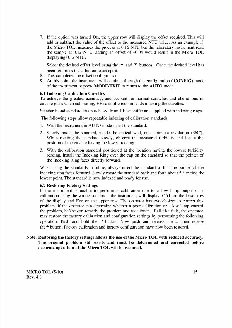
7.1 Selecting the Output (O/P)The first configuration selection is the O/P. The selections are 4-20 for the 4-20 mA
output, 485 for the RS-485 and OFF if no outputs are required. Select the desired output
by using the t and u buttons. Once the desired output has been set, press the ↵ button
to accept it. The next prompts will depend on the output selected.
7.2 Setting the 4-20 mA
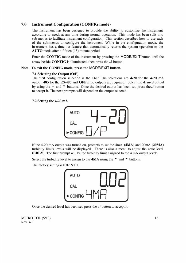
If the 4-20 mA output was turned on, prompts to set the 4mA (4MA) and 20mA (20MA) turbidity limits levels will be displayed. There is also a menu to adjust the error level
(ERLV). The first prompt will be the turbidity limit assigned to the 4 mA output level:
Select the turbidity level to assign to the 4MA using thet andu buttons.
The factory setting is 0.02 NTU.
Once the desired level has been set, press the ↵ button to accept it.
Note: The 4MA can be set higher than the 20 MA level to invert the output current if
required. This may be required to control a dosing pump
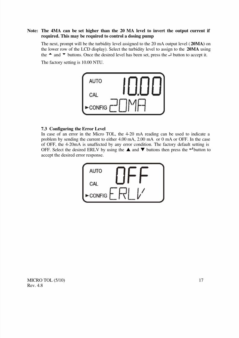
The next, prompt will be the turbidity level assigned to the 20 mA output level (20MA) on
the lower row of the LCD display). Select the turbidity level to assign to the 20MA using
thet andu buttons. Once the desired level has been set, press the ↵ button to accept it.
The factory setting is 10.00 NTU.
7.3 Configuring the Error LevelIn case of an error in the Micro TOL, the 4-20 mA reading can be used to indicate aproblem by sending the current to either 4.00 mA, 2.00 mA or 0 mA or OFF. In the caseof OFF, the 4-20mA is unaffected by any error condition. The factory default setting is
OFF. Select the desired ERLV by using the S and T buttons then press the button to
7.4 Configuring the RS–485 PortIf the instrument is equipped with this option, and the I/O selection is changed to 485,prompts will appear for setting the baud rate and the address.
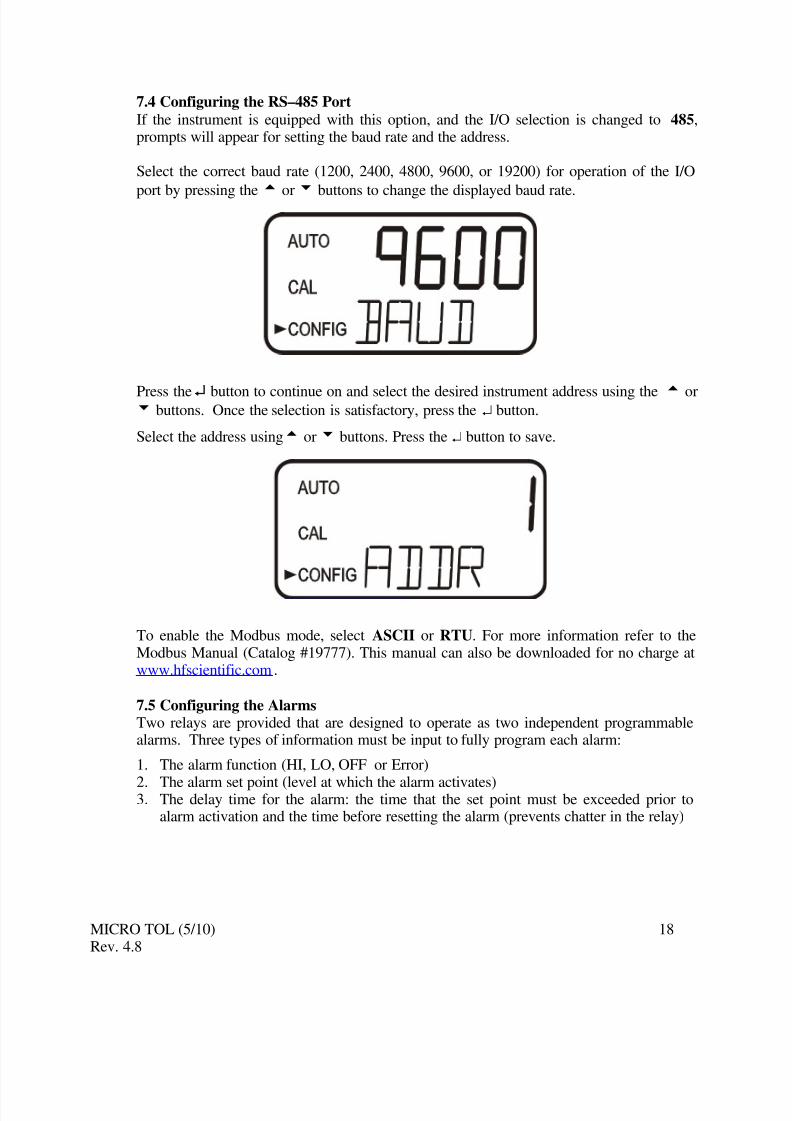
Select the correct baud rate (1200, 2400, 4800, 9600, or 19200) for operation of the I/O
port by pressing thet
oru
buttons to change the displayed baud rate.
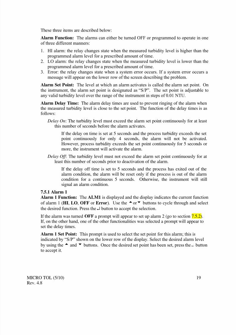
Press the ↵ button to continue on and select the desired instrument address using thet
oru buttons. Once the selection is satisfactory, press the ↵ button.
Select the address usingt oru buttons. Press the ↵ button to save.
To enable the Modbus mode, select ASCII or RTU. For more information refer to theModbus Manual (Catalog #19777). This manual can also be downloaded for no charge atwww.hfscientific.com.
7.5 Configuring the AlarmsTwo relays are provided that are designed to operate as two independent programmablealarms. Three types of information must be input to fully program each alarm:
1. The alarm function (HI, LO, OFF or Error)
2. The alarm set point (level at which the alarm activates)3. The delay time for the alarm: the time that the set point must be exceeded prior to
alarm activation and the time before resetting the alarm (prevents chatter in the relay)
Alarm Function: The alarms can either be turned OFF or programmed to operate in one
of three different manners:
1. HI alarm: the relay changes state when the measured turbidity level is higher than the
programmed alarm level for a prescribed amount of time.
2. LO alarm: the relay changes state when the measured turbidity level is lower than the
programmed alarm level for a prescribed amount of time.3. Error: the relay changes state when a system error occurs. If a system error occurs a
message will appear on the lower row of the screen describing the problem.
Alarm Set Point: The level at which an alarm activates is called the alarm set point. On
the instrument, the alarm set point is designated as “S/P”. The set point is adjustable toany valid turbidity level over the range of the instrument in steps of 0.01 NTU.
Alarm Delay Time: The alarm delay times are used to prevent ringing of the alarm whenthe measured turbidity level is close to the set point. The function of the delay times is asfollows:
Delay On: The turbidity level must exceed the alarm set point continuously for at leastthis number of seconds before the alarm activates.
If the delay on time is set at 5 seconds and the process turbidity exceeds the setpoint continuously for only 4 seconds, the alarm will not be activated.However, process turbidity exceeds the set point continuously for 5 seconds ormore, the instrument will activate the alarm.
Delay Off : The turbidity level must not exceed the alarm set point continuously for atleast this number of seconds prior to deactivation of the alarm.
If the delay off time is set to 5 seconds and the process has exited out of the
alarm condition, the alarm will be reset only if the process is out of the alarmcondition for a continuous 5 seconds. Otherwise, the instrument will stillsignal an alarm condition.
7.5.1 Alarm 1Alarm 1 Function: The ALM1 is displayed and the display indicates the current function
of alarm 1 (HI, LO, OFF or Error). Use the tor u buttons to cycle through and select
the desired function. Press the ↵ button to accept the selection.
If the alarm was turned OFF a prompt will appear to set up alarm 2 (go to section 7.5.2).If, on the other hand, one of the other functionalities was selected a prompt will appear toset the delay times.
Alarm 1 Set Point: This prompt is used to select the set point for this alarm; this isindicated by “S/P” shown on the lower row of the display. Select the desired alarm level
by using thet and u buttons. Once the desired set point has been set, press the ↵ buttonto accept it.
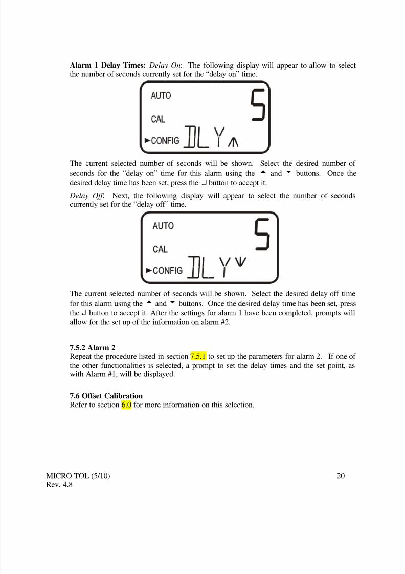
Alarm 1 Delay Times: Delay On: The following display will appear to allow to selectthe number of seconds currently set for the “delay on” time.
The current selected number of seconds will be shown. Select the desired number of
seconds for the “delay on” time for this alarm using the t and u buttons. Once the
desired delay time has been set, press the ↵ button to accept it.
Delay Off : Next, the following display will appear to select the number of secondscurrently set for the “delay off” time.
The current selected number of seconds will be shown. Select the desired delay off time
for this alarm using thet andu buttons. Once the desired delay time has been set, pressthe ↵ button to accept it. After the settings for alarm 1 have been completed, prompts willallow for the set up of the information on alarm #2.
7.5.2 Alarm 2Repeat the procedure listed in section 7.5.1 to set up the parameters for alarm 2. If one of the other functionalities is selected, a prompt to set the delay times and the set point, aswith Alarm #1, will be displayed.
7.6 Offset Calibration
Refer to section 6.0 for more information on this selection.
7.7 Enabling the Security AccessThe instrument is equipped with a security access. If this option is turned on, the user is
required to input the access code into the instrument to get to any mode other than AUTO.The only code is 333. This code may not be changed. See section 4.2 for moreinformation on this security feature. The security key icon will be visible and flashing on
the display whenever the access option is selected using thet
oru
buttons. (On orOFF).
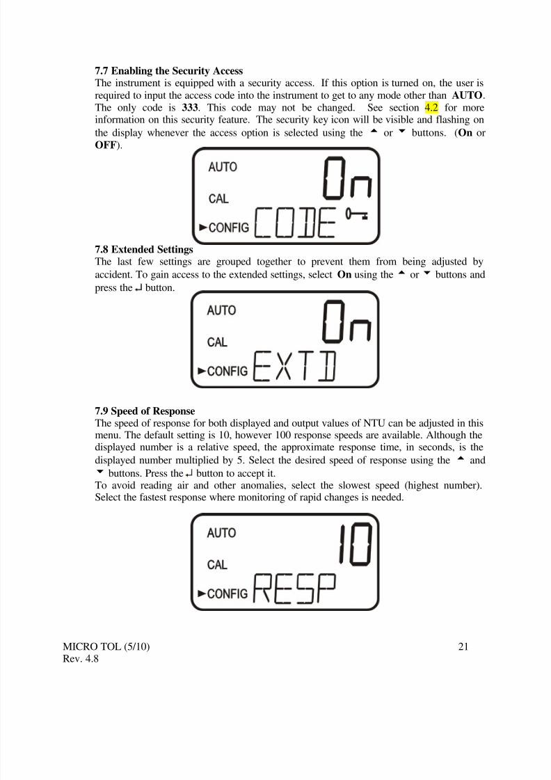
7.8 Extended SettingsThe last few settings are grouped together to prevent them from being adjusted by
accident. To gain access to the extended settings, select On using thet oru buttons andpress the ↵ button.
7.9 Speed of ResponseThe speed of response for both displayed and output values of NTU can be adjusted in thismenu. The default setting is 10, however 100 response speeds are available. Although thedisplayed number is a relative speed, the approximate response time, in seconds, is the
displayed number multiplied by 5. Select the desired speed of response using the t and
u buttons. Press the ↵ button to accept it.To avoid reading air and other anomalies, select the slowest speed (highest number).Select the fastest response where monitoring of rapid changes is needed.
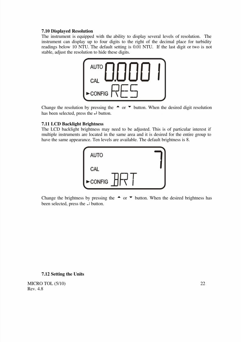
7.10 Displayed ResolutionThe instrument is equipped with the ability to display several levels of resolution. Theinstrument can display up to four digits to the right of the decimal place for turbidityreadings below 10 NTU. The default setting is 0.01 NTU. If the last digit or two is notstable, adjust the resolution to hide these digits.
Change the resolution by pressing the t or u button. When the desired digit resolution
has been selected, press the ↵ button.
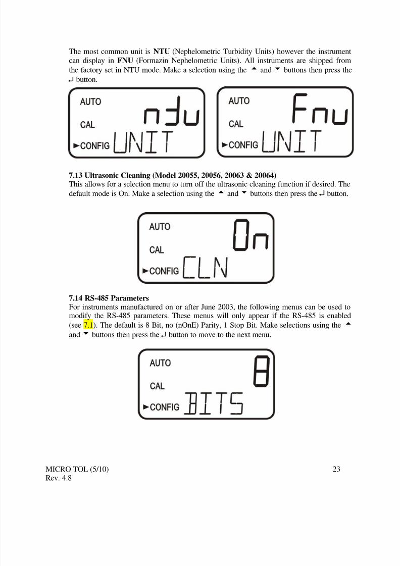
7.11 LCD Backlight BrightnessThe LCD backlight brightness may need to be adjusted. This is of particular interest if multiple instruments are located in the same area and it is desired for the entire group tohave the same appearance. Ten levels are available. The default brightness is 8.
Change the brightness by pressing the t or u button. When the desired brightness has
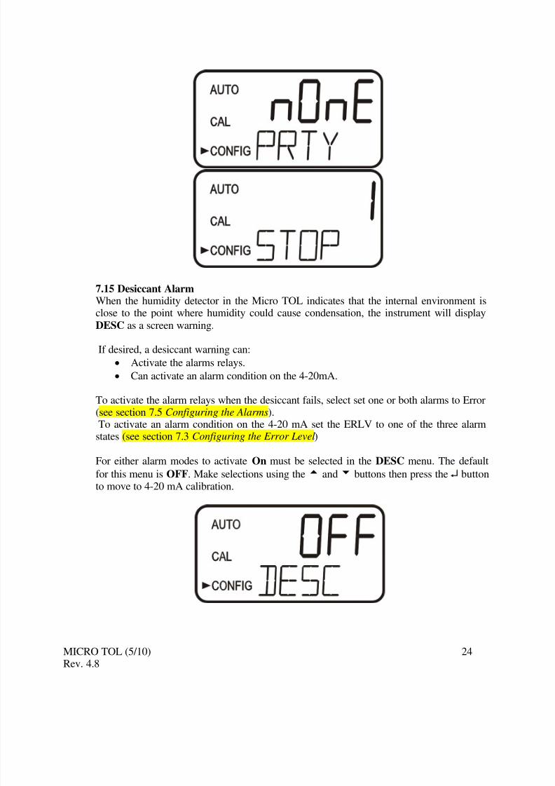
The most common unit is NTU (Nephelometric Turbidity Units) however the instrument
can display in FNU (Formazin Nephelometric Units). All instruments are shipped from
the factory set in NTU mode. Make a selection using the t andu buttons then press the
↵ button.
7.13 Ultrasonic Cleaning (Model 20055, 20056, 20063 & 20064)This allows for a selection menu to turn off the ultrasonic cleaning function if desired. The
default mode is On. Make a selection using the t andu buttons then press the ↵ button.
7.14 RS-485 Parameters For instruments manufactured on or after June 2003, the following menus can be used tomodify the RS-485 parameters. These menus will only appear if the RS-485 is enabled
(see 7.1). The default is 8 Bit, no (nOnE) Parity, 1 Stop Bit. Make selections using the t
andu buttons then press the ↵ button to move to the next menu.
7.15 Desiccant AlarmWhen the humidity detector in the Micro TOL indicates that the internal environment isclose to the point where humidity could cause condensation, the instrument will display
DESC as a screen warning.
If desired, a desiccant warning can:
• Activate the alarms relays.
• Can activate an alarm condition on the 4-20mA.
To activate the alarm relays when the desiccant fails, select set one or both alarms to Error
(see section 7.5 Configuring the Alarms).To activate an alarm condition on the 4-20 mA set the ERLV to one of the three alarmstates (see section 7.3 Configuring the Error Level)
For either alarm modes to activate On must be selected in the DESC menu. The default
for this menu is OFF. Make selections using thet andu buttons then press the ↵ buttonto move to 4-20 mA calibration.
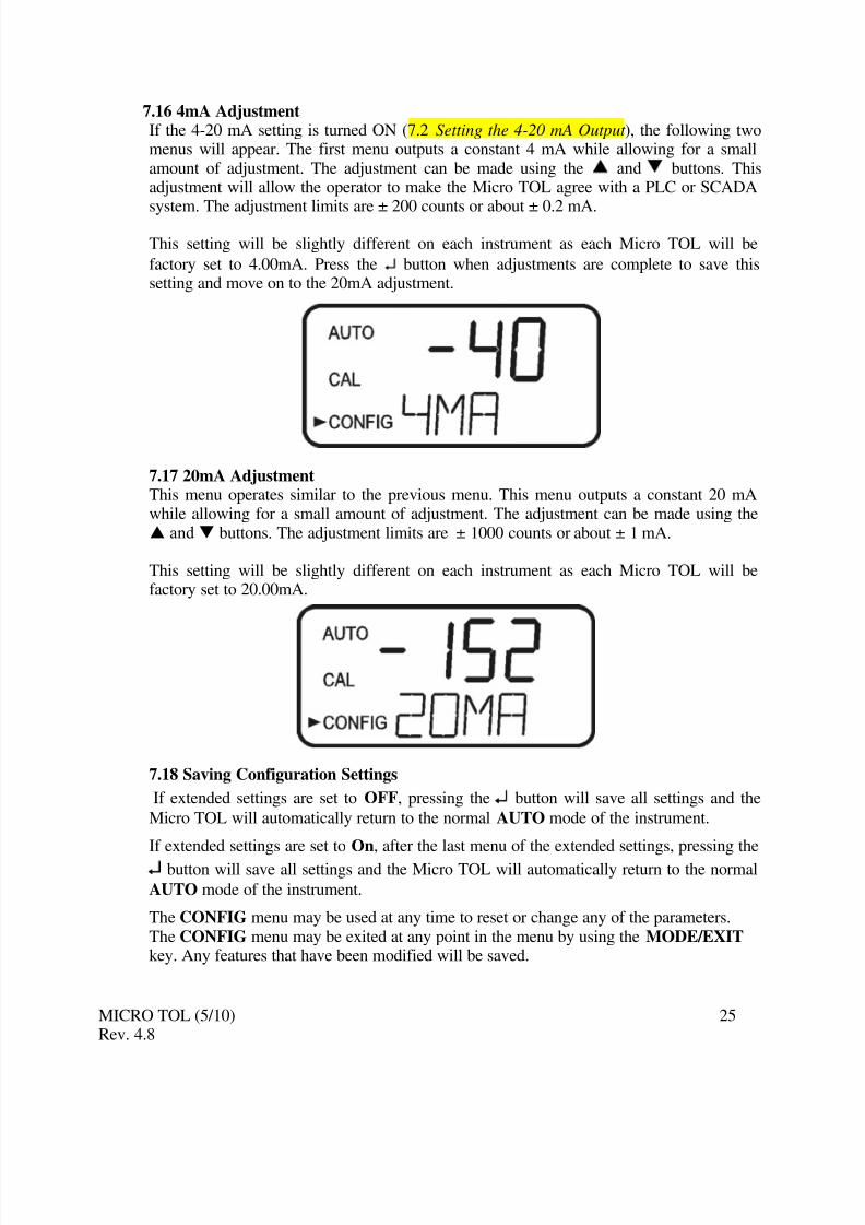
7.16 4mA AdjustmentIf the 4-20 mA setting is turned ON (7.2 Setting the 4-20 mA Output ), the following twomenus will appear. The first menu outputs a constant 4 mA while allowing for a smallamount of adjustment. The adjustment can be made using the S and T buttons. Thisadjustment will allow the operator to make the Micro TOL agree with a PLC or SCADA
system. The adjustment limits are ± 200 counts or about ± 0.2 mA.
This setting will be slightly different on each instrument as each Micro TOL will be
factory set to 4.00mA. Press the ↵ button when adjustments are complete to save thissetting and move on to the 20mA adjustment.
7.17 20mA AdjustmentThis menu operates similar to the previous menu. This menu outputs a constant 20 mAwhile allowing for a small amount of adjustment. The adjustment can be made using theS and T buttons. The adjustment limits are ± 1000 counts or about ± 1 mA.
This setting will be slightly different on each instrument as each Micro TOL will befactory set to 20.00mA.
7.18 Saving Configuration Settings
If extended settings are set to OFF, pressing the ↵ button will save all settings and the
Micro TOL will automatically return to the normal AUTO mode of the instrument.
If extended settings are set to On, after the last menu of the extended settings, pressing the
↵ button will save all settings and the Micro TOL will automatically return to the normal
AUTO mode of the instrument.
The CONFIG menu may be used at any time to reset or change any of the parameters.The CONFIG menu may be exited at any point in the menu by using the MODE/EXIT key. Any features that have been modified will be saved.
8.1 Backlit LCDThe backlit LCD allows for easier readability of the LCD display in low light or no lightconditions. The backlight is intended for continuous operation. The brightness is
adjustable from a menu in the CONFIG mode.8.2 Ultrasonic Cleaning (Models 20055, 20056, 20063 & 20064)This factory installed option is used to continuously clean the flow through cuvette. It isnot intended to clean cuvettes that are already dirty, or replace manual cleaning entirely.The system will increase the time between cleanings dramatically. Please note that thesystem requires the use of a special cuvette. This cuvette must be used for the system tooperate correctly.
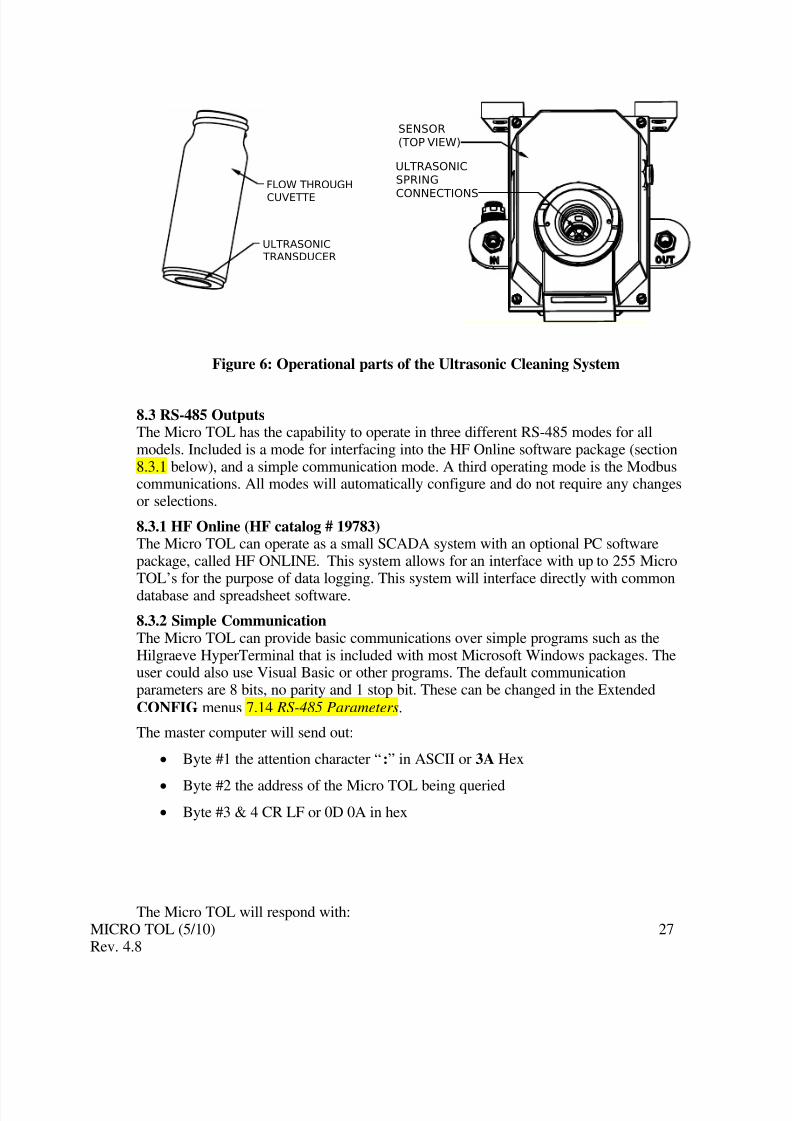
The system works by sending an ultrasonic frequency through spring connections into apiezo transducer bonded to the bottom of a flow through cuvette (refer to figure 6).
The system can detect that an incorrect cuvette is installed, an error has occurred in the
transducer or the transducer is not making contact with the spring connections. This erroris indicated by CLN being posted to the lower screen. Since this is an error condition, thismay affect the 4-20 mA and alarms depending in the setting of the ERLV (4-20 mA) andif an alarm is set up to Error.
If the correct cuvette is installed, and the error is still posted, try rotating the flow throughunit slightly to improve the connection. If this fails to work, the cuvette may have to be
replaced (Catalog #24166S). The detection for this cuvette only operates in AUTO mode.If the system is operating correctly AUTO will flash on the display.
Hint: The connection can be improved with use of a small film of an anti-oxidant compound
such as OX-GARD ™ made by GB Electrical Inc. This product is available in the
electrical section at most hardware stores.
Note: The cuvette must be completely dry before it is inserted into the sensor. If there is
any visible moisture present on the cuvette or transducer, there is a great risk of
damaging the sensor electronics and the transducer. Be sure to clean and dry thecuvette completely just before inserting it into the sensor.
The Vapor Purge system can NOT remove large droplets of water, only residual moisture.
Note: For the Vapor Purge system to function properly, all instrument seals must bemaintained and the desiccant pack must be in good condition (no DESC display).
Figure 6: Operational parts of the Ultrasonic Cleaning System
8.3 RS-485 OutputsThe Micro TOL has the capability to operate in three different RS-485 modes for allmodels. Included is a mode for interfacing into the HF Online software package (section8.3.1 below), and a simple communication mode. A third operating mode is the Modbuscommunications. All modes will automatically configure and do not require any changesor selections.
8.3.1 HF Online (HF catalog # 19783)The Micro TOL can operate as a small SCADA system with an optional PC softwarepackage, called HF ONLINE. This system allows for an interface with up to 255 MicroTOL’s for the purpose of data logging. This system will interface directly with commondatabase and spreadsheet software.
8.3.2 Simple CommunicationThe Micro TOL can provide basic communications over simple programs such as theHilgraeve HyperTerminal that is included with most Microsoft Windows packages. Theuser could also use Visual Basic or other programs. The default communicationparameters are 8 bits, no parity and 1 stop bit. These can be changed in the Extended
CONFIG menus 7.14 RS-485 Parameters.
The master computer will send out:
• Byte #1 the attention character “:” in ASCII or 3A Hex
• Byte #2 the address of the Micro TOL being queried
• The same attention character “:” in ASCII or 3A Hex
• The address of the Micro TOL
• The Reading
• The Unit (NTU)
A sample communication would look like this:
(Master computer requesting a report from address #1) : 1 CRLF
(Micro TOL set to address #1 Response) :001 0.0249 NTU
8.3.3 Modbus CommunicationModbus protocol communication is operational on all models. The Modbus information iscovered in a separate manual (Catalog # 19777). This manual is also available as a freedownload from our website at www.hfscientific.com.
8.4 Flow Alarm (Catalog # 19945A)The flow switch for the Micro TOL is a factory-installed option. This option indicates a
“Low Flow” condition by switching both relays to the fail state and setting the 4-20 mAsignal to 2 mA. There is also a screen indication of the low flow condition and a modbusregister is set.
8.5 Flow Controller (Catalog # 19778)The flow controller limits the flow, in high-pressure systems, to safe flow limits of lessthan 1 liter/minute.
8.6 Remote Panel Meter (Catalog # 19609) The remote panel meter allows for remote indication of the NTU reading using the 4-20mA loop. No external power is required as the meter is run off of the 4-20 mA source.
9.1 Micro TOL Fault DetectionThe Micro TOL performs continuous diagnostic monitoring. In the Micro TOL there arethree levels of fault detection; warnings, errors and failures. Any faults are displayed in aqueue form in the bottom row of the LCD. How these faults are indicated depends on the
settings made in sections 7.3 Configuring the Error Level and 7.5 Configuring the Alarms. If ERLV is set to OFF and Alarms are not set to Error, there will be no remote,indication of a problem.
If the desiccant alarm is turned off and the desiccant becomes saturated only a screen
warning of DESC will appear and no alarms are activated. Another warning of ALM1
or ALM2 is displayed if an alarm is set and the threshold is exceeded.
An error indicates a failure or a problem that usually can be corrected by the operator.These errors consist of:
• Lamp out LAMP.
• 4-20 mA loop open MA.• Bad calibration CAL.
• If desiccant alarm activated and replacement required DESC.
• If enabled and no flow FLOW (if equipped with the flow switch).
• If the Micro TOL is equipped with ultrasonic cleaning, an additional message willindicate that the ultrasonic transducer is not making contact or the flow through
has been removed CLN.
If any of these errors occur the instrument will still display readings, however the accuracyis not known and the instruments readings may not be reliable.
A failure is a system fault. This is NOT a problem that the operator can correct, and the
unit must be returned to the factory for service. These failures consist of failures in theCPU, A/D, EEPROM or other devices internal to the instrument (FAIL). If a failureoccurs, the instrument will not function properly and will display the word FAIL on thelower row.
If any fault conditions occur, the message indicating the fault will be shown on the lowerrow of the display.
9.2 System FAIL MessageNormally, this condition indicates that the instrument will require servicing. Contact eitherthe HF scientific Technical Service Department or the HF scientific Customer ServiceDepartment.
HF scientific3170 Metro Parkway
Fort Myers, Florida 33916-7597Phone: (239) 337-2116Fax: (239) 332-7643
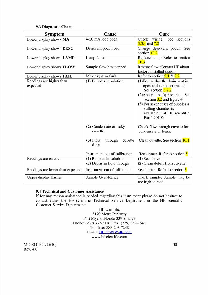
Lower display shows FAIL Major system fault Refer to section 9.1 & 9.2
Readings are higher thanexpected
(1) Bubbles in solution
(2) Condensate or leakycuvette
(3) Flow through cuvettedirty
Instrument out of calibration
(1)Ensure that the drain vent isopen and is not obstructed.See section 3.2.2.
(2)Apply backpressure. Seesection 3.2 and figure 4
(3) For sever cases of bubbles astilling chamber isavailable. Call HF scientific.Part# 20106
Check flow through cuvette forcondensate or leaks.
Clean cuvette. See section 10.1
Recalibrate. Refer to section 5Readings are erratic (1) Bubbles in solution
(2) Debris in flow through(1) See above
(2) Clean debris from cuvette
Readings are lower than expected Instrument out of calibration Recalibrate. Refer to section 5
Upper display flashes Sample Over-Range Check sample. Sample may betoo high to read.
9.4 Technical and Customer AssistanceIf for any reason assistance is needed regarding this instrument please do not hesitate tocontact either the HF scientific Technical Service Department or the HF scientific
Customer Service Department: HF scientific3170 Metro Parkway
Fort Myers, Florida 33916-7597Phone: (239) 337-2116 Fax: (239) 332-7643
10.1 Cleaning the Flow Through CuvetteMeasurement cuvettes used for both grab sample and the flow through should be cleanand free of marks or scratches. Cleaning is accomplished by cleaning the interior andexterior with a detergent solution and then rinsing several times with distilled or de-
ionized water. The cuvette can be replaced by first shutting off the flow using the providedshutoff clamp; unscrewing the old cuvette and replacing with a fresh clean one.
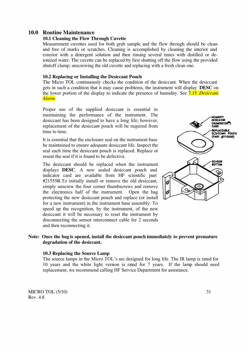
10.2 Replacing or Installing the Desiccant Pouch The Micro TOL continuously checks the condition of the desiccant. When the desiccant
gets in such a condition that it may cause problems, the instrument will display DESC onthe lower portion of the display to indicate the presence of humidity. See 7.15 Desiccant Alarm.
Proper use of the supplied desiccant is essential in
maintaining the performance of the instrument. Thedesiccant has been designed to have a long life; however,
replacement of the desiccant pouch will be required from
time to time.
It is essential that the enclosure seal on the instrument base be maintained to ensure adequate desiccant life. Inspect the
seal each time the desiccant pouch is replaced. Replace or
reseat the seal if it is found to be defective.
The desiccant should be replaced when the instrument
displays DESC. A new sealed desiccant pouch andindicator card are available from HF scientific part
#21555R.To initially install or remove the old desiccant,
simply unscrew the four corner thumbscrews and removethe electronics half of the instrument. Open the bag
protecting the new desiccant pouch and replace (or install
for a new instrument) in the instrument base assembly. To
speed up the recognition, by the instrument, of the newdesiccant it will be necessary to reset the instrument by
disconnecting the sensor interconnect cable for 2 seconds
and then reconnecting it.
Note: Once the bag is opened, install the desiccant pouch immediately to prevent premature
degradation of the desiccant.
10.3 Replacing the Source LampThe source lamps in the Micro TOL’s are designed for long life. The IR lamp is rated for 10 years and the white light version is rated for 7 years. If the lamp should need
replacement, we recommend calling HF Service Department for assistance.
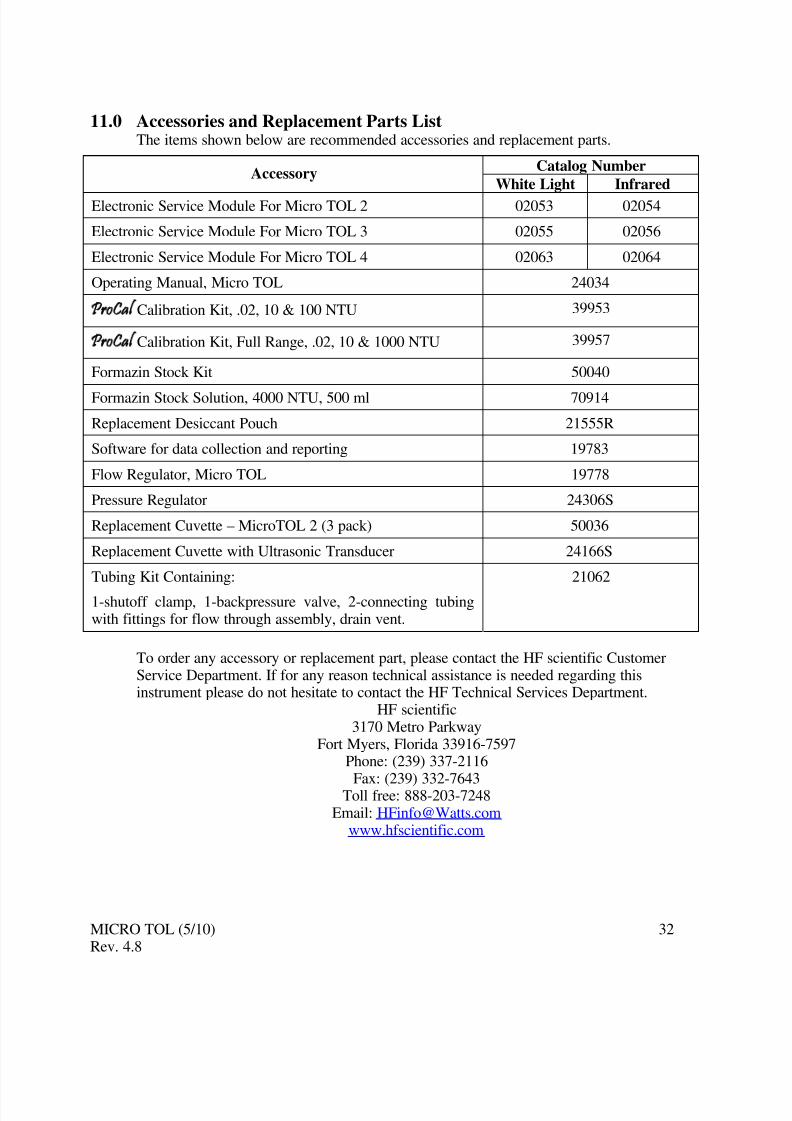
Replacement Cuvette with Ultrasonic Transducer 24166S
Tubing Kit Containing:
1-shutoff clamp, 1-backpressure valve, 2-connecting tubingwith fittings for flow through assembly, drain vent.
21062
To order any accessory or replacement part, please contact the HF scientific CustomerService Department. If for any reason technical assistance is needed regarding thisinstrument please do not hesitate to contact the HF Technical Services Department.
HF scientific3170 Metro Parkway
Fort Myers, Florida 33916-7597Phone: (239) 337-2116
12.0 WarrantyHF scientific inc., as vendor, warrants to the original purchaser of this instrument that itwill be free of defects in material and workmanship, in normal use and service, for a
period of one year from date of delivery to the original purchaser. HF scientific inc.’s
obligation under this warranty is limited to replacing, at its factory, the instrument or any
part thereof. Parts, which by their nature are normally required to be replaced periodically, consistent with normal maintenance, specifically reagent, desiccant, sensors,
electrodes and fuses are excluded. Also excluded are accessories and supply type items.
Original purchaser is responsible for return of the instruments, or parts thereof, to HFscientific’ inc.’s factory. This includes all freight charges incurred in shipping to and from
HF scientific inc.’s factory.
HF scientific inc .is not responsible for damage to the instrument, or parts thereof,
resulting from misuse, environmental corrosion, negligence or accident, or defectsresulting from repairs, alterations or installation made by any person or company not
authorized by HF scientific inc.
HF scientific inc. assumes no liability for consequential damage of any kind, and theoriginal purchaser, by placement of any order for the instrument, or parts thereof, shall be
deemed liable for any and all damages incurred by the use or misuse of the instruments, or parts thereof, by the purchaser, its employees, or others, following receipt thereof.
Carefully inspect this product for shipping damage, if damaged, immediately notify the
shipping company and arrange an on-site inspection. HF scientific inc cannot be
responsible for damage in shipment and cannot assist with claims without an on-siteinspection of the damage.
This warranty is given expressly and in lieu of all other warranties, expressed or implied.
Purchaser agrees that there is no warranty on merchantability and that there are no other
warranties, expressed or implied. No agent is authorized to assume for HF scientific inc.,any liability except as set forth above.