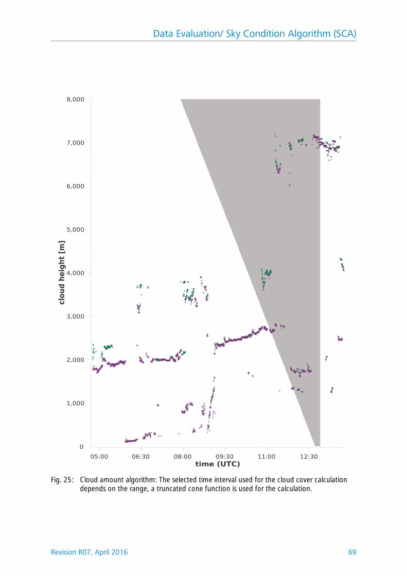
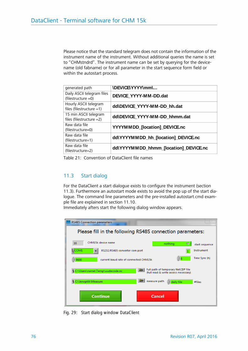
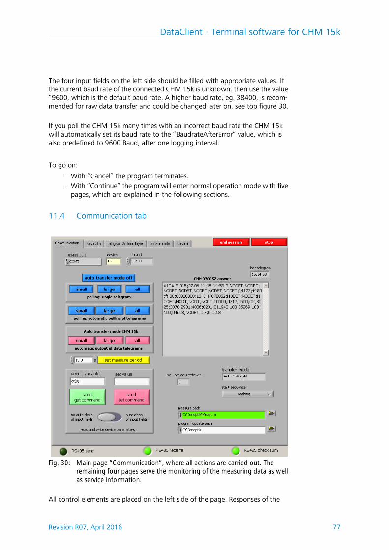
Manual Ceilometer CHM 15k „NIMBUS“ www.lufft.com · a passion for precision · passion pour la précision · pasión por la precisión · passion e per la precisione · a p 1300m 1500m Jenoptik Laser Technology Inside
Transcript
Manual Ceilometer CHM 15k „NIMBUS“
www.lufft.com
· a passion for precision · passion pour la précision · pasión por la precisión · passione per la precisione · a p
Jenoptik Laser Technology inside
1300m
1500m
Jenoptik Laser Technology Inside
Dear User
2 Revision R07, April 2016
NoteThis Manual is protected by copyright. No part of the Manual may be reproduced in any way (by photographing, photocopying, microfilm or any other technique) without the prior written approval of G. Lufft, nor may it be processed, duplicated or disseminated with the help of elec-tronic systems. Any offence against these rules will be prosecuted.
Proper care was used in compiling this document. No liability will be accepted in the event of damage resulting from failure to comply with information provided herein.
Documentation number: 8350.MEP
This documentation is valid for the following instrument types:CHM 15k Nimbus series with order numbers: 8350.00, 8350.01, 8350.03
Date Revision CommentMarch 2014 I0 Firmware 0.723, last Jenoptik release
September 2014 R02Firmware 0.724, Lufft design, 10m range resolution in NetCDF available, small corrections
December 2014 R04Firmware 0.730, cloud algorithm optimized in precipitation cases, param-eter in RS485 / web-interface added, chapter 7-8 corrected
May 2015 R05 Firmware 0.732October 2015 R06 Firmware 0.735, small fixesNovember 2015 R07 Small fixes chapter 9, table SCIApril 2016 coming soon
You are advised to read this Manual carefully before you start using the CHM 15k Nimbus / CHM 15k-x ceilometer.
This is necessary to ensure that you will be able to utilize all the capabilities, which have been designed into the equipment.
This technology is subject to further development.
WARRANTY AND ASSISTANCE This equipment is warranted by CAMPBELL SCIENTIFIC (CANADA) CORP. ("CSC") to be free from defects in materials and workmanship under normal use and service for
twenty-four (24) months from date of shipment unless specified otherwise. *****
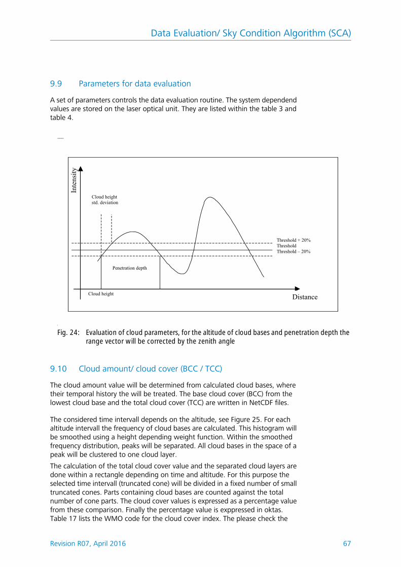
Batteries are not warranted. ***** CSC's obligation under this warranty is limited to
repairing or replacing (at CSC's option) defective products. The customer shall assume all costs of removing, reinstalling, and shipping defective products to CSC. CSC will
return such products by surface carrier prepaid. This warranty shall not apply to any CSC products which have been subjected to modification, misuse, neglect, accidents of
nature, or shipping damage. This warranty is in lieu of all other warranties, expressed or implied, including warranties of merchantability or fitness for a particular purpose. CSC
is not liable for special, indirect, incidental, or consequential damages.
Products may not be returned without prior authorization. To obtain a Return
This User Manual provides the information that is required to operate the CHM 15k Cloud Height Meter.
1.1 Manual Structuring & Layout Note
The Manual consists of eleven chapters, each page indicating the chapter title in its headline.
The bottom line of each page contains the details of the revision state, date of issue and page number. In the appendix a content list of the service manual, a list of software releases for this manual revision and a configuration example is applied.
1.2 Intended Use
Operating safety can only be guaranteed when the CHM 15k Cloud Height Meter is operated as intended and in accordance with the information contained in this Manual.
The CHM 15k is only intended for single-phase operation powered by a public low-voltage distri-bution system as stipulated in IEC38, 6th revision of 1983.
The Cloud Height Meter may be used with a maximum tilt angle setting of 20 degrees. Any angle setting in excess of this limit will be regarded as non-conforming use! The owner (operator) will be solely responsible in the event of damage due to non-compliance of this kind.
You are strictly prohibited from using the CHM 15k in a horizontal position.
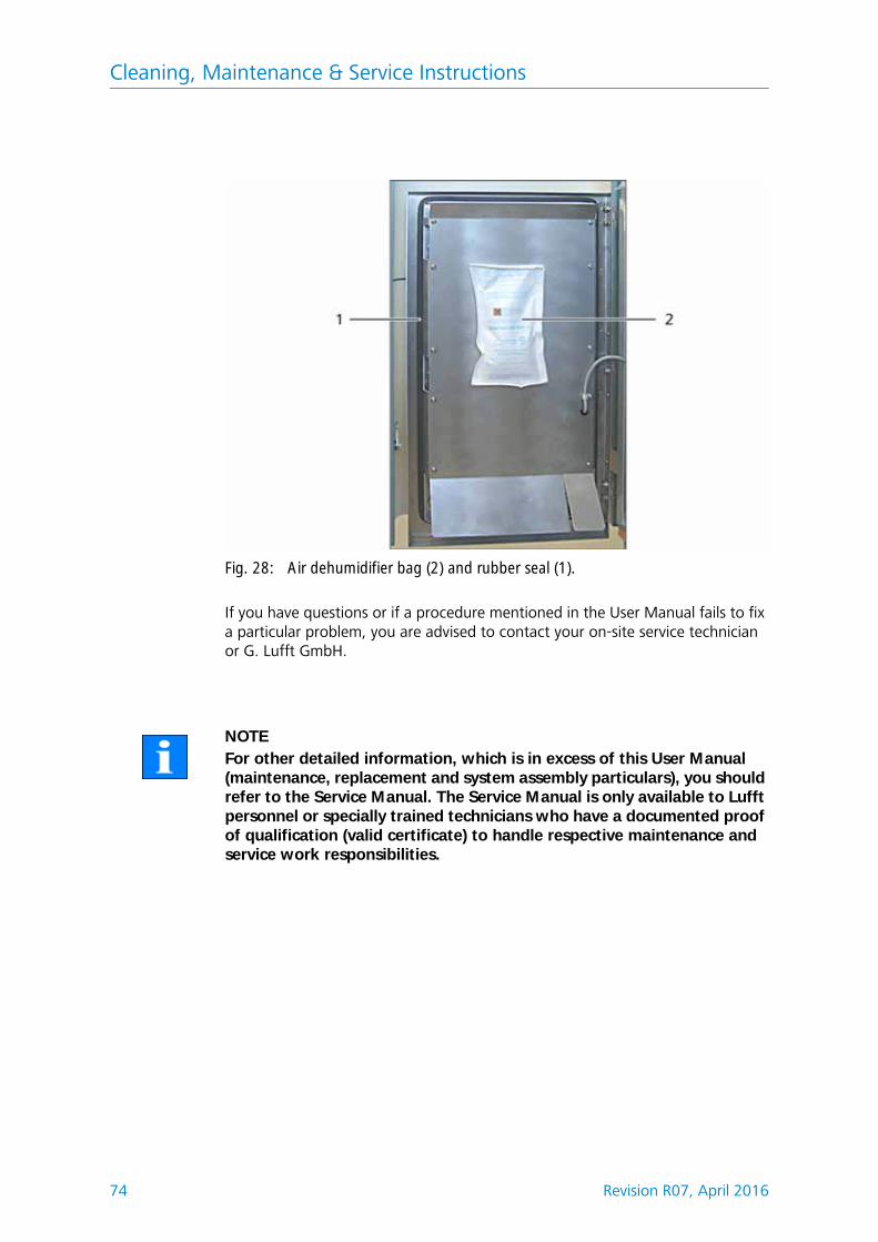
For proper operation, scheduled cleaning and maintenance cycles must be observed (refer to chapter 10 of this Manual or to the Service Manual).
Safety
Revision R07, April 2016 7
2 Safety
2.1 Standards & Directives
To guarantee the safe operation of laser devices, all binding standards, directives and instructions regarding laser safety and laser radiation protection must be observed by manufacturers and users (refer to Declaration of Conformity).
The CHM 15k Cloud Height Meter is built and tested for compliance with the following standards and directives:
1. Council Directive 2004/108/EECon the approximation of the laws of the Member States relating toelectromagnetic compatibility (EMC),conforming to EN 61326 and EN 55011 standard requirements
2. Council Directive 2006/95/EECrelating to electrical equipment designed for use within certain voltage lim-its (73/23/EEC)conforming to the following standards:– EN 60825-1; Safety of laser products– EN 61010-1; Safety requirements for electrical equipment for measure-
ment, control and laboratory use
In accordance with EN 60825-1:2007 and its inherent risk potential, the CHM 15k qualifies as a class 1M laser device.
2.2 General Safety Measures
l All safety notes in this User Manual, including any other applicable docu-ments, must be duly observed and followed.
l This User Manual must be kept within easy reach of personnel at all times.l The CHM 15k may only be operated with the inner door closed.l The CHM 15k Cloud Height Meter may not be powered by nominal volt-
ages other than 230 VAC.
2.3 Safety Notes Regarding the Laser System
There is invisible 1064-nm laser radiation emerging from the CHM 15k. It emits a laser beam of very small divergence (< 0.5 mrad) and 90 mm beam diameter.
l Do not directly look into the beam.l Avoid unnecessary exposure to invisible laser radiation.l It is strictly forbidden to use optical instruments, notably, field glasses, for
viewing the laser beam.l Class 1M laser radiation, if viewed over an extended period of time,
may cause damage to the eyes such as glare or irritation or even full loss of eyesight.
l Make sure the laser beam path is free from material with reflecting sur-faces.
l Follow all instructions especially those on emergence of laser radiation (also
Safety
8 Revision R07, April 2016
refer to chapter 2.6 Safety Labelling).
2.4 Requirements on Personnel
l The CHM 15k may only be installed and commissioned by properly trained personnel who have received instructions on operating safety.
l Maintenance or adjustment work on the CHM 15k may only be carried byG. Lufft GmbH service personnel or specially trained and authorized techni-cians of the Customer.
l Anyone who is entrusted with work to install and commission the CHM 15k must have completely read and understood this Manual.
l Personnel working with the CHM 15k must not be in a state of fatigue or under the influence of alcohol or medication or have physical impairments of any kind that might temporarily or lastingly restrict their attention or judgement.
l For handling, shipment or transportation, the CHM 15k must be duly pack-aged and placed in the transporting position (refer to Fig. 5). Adequate hoisting equipment and an appropriate means of transportation must be used in all cases.
l Once packaged, the CHM 15k must be secured and protected against acci-dental shifting, mechanical shock or other similar impacts that may occur inside the selected means of transportation, for example, by using tension belts.
l A packaged CHM 15k must not be stacked.l The CHM 15k requires a footprint area of 50 x 50 cm. It must be installed
and assembled in a stable and fixed position on a suitably sized concrete foundation. The maximum permitted inclination angle of the mounting base is 5 mm/m.
l If the CHM 15k is not intended to be assembled immediately, it must be protected from external influences and securely stored.
l For installation, the following minimum prescribed clearances must be kept betweenthe CHM 15k and:
l Prevent irradiation from strong light sources.l The angle of insolation must be less or equal 15 degrees against the vertical
line. Please ask for a suiable adapter plates.l The assembly site must be at a great enough distance from tree plantations
or shrubbery to prevent leaves or needles restricting the cloud meter's light outlet openings.
l At least two persons are required for installation of the CHM 15k.l On completion of installation work, ensure that no safety-relevant changes
- mobile phones 2,5 m
- stationary emitters, ground stations ( 100 W of output power) 25 m
- a second cloud height meter (to prevent optical interferences) 10 m
Safety
Revision R07, April 2016 9
have impacted the CHM 15k during installation.
2.6 Safety Labelling
2.6.1 User Manual
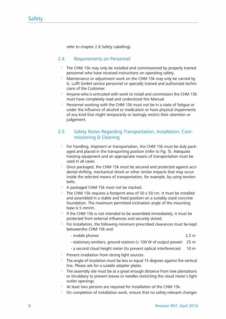
Throughout this Manual the following pictograms and signal words are used:
DANGERWarns of laser radiation
CAUTIONWarns of potential damage
NOTEImportant general note
NOTEImportant note on environmental protection
Safety
10 Revision R07, April 2016
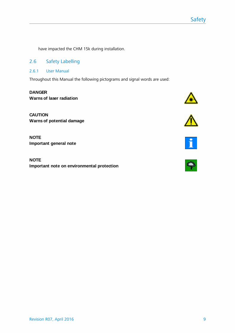
2.6.2 CHM 15k
Product labelling is as follows (see Fig. 1):l 4 warning labels with safety notesl 1 plate with performance datal 1 "Beware of Laser Radiation" warning labell 1 type plate (rear side)
Fig. 1: Labelling
1
Technical Data
Revision R07, April 2016 11
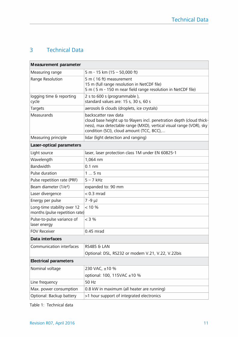
3 Technical Data
Measurement parameter
Measuring range 5 m - 15 km (15 – 50,000 ft)
Range Resolution 5 m ( 16 ft) measurement15 m (full range resolution in NetCDF file)5 m ( 5 m - 150 m near field range resolution in NetCDF file)
logging time & reporting cycle
2 s to 600 s (programmable ),standard values are: 15 s, 30 s, 60 s
Measurands backscatter raw datacloud base height up to 9layers incl. penetration depth (cloud thick-ness), max detectable range (MXD), vertical visual range (VOR), sky condition (SCI), cloud amount (TCC, BCC),...
Measuring principle lidar (light detection and ranging)
Laser-optical parameters
Light source laser, laser protection class 1M under EN 60825-1
Wavelength 1,064 nm
Bandwidth 0.1 nm
Pulse duration 1 ... 5 ns
Pulse repetition rate (PRF) 5 – 7 kHz
Beam diameter (1/e²) expanded to: 90 mm
Laser divergence < 0.3 mrad
Energy per pulse 7 -9 μJ
Long-time stability over 12 months (pulse repetition rate)
< 10 %
Pulse-to-pulse variance of laser energy
< 3 %
FOV Receiver 0.45 mrad
Data interfaces
Communication interfaces RS485 & LAN
Optional: DSL, RS232 or modem V.21, V.22, V.22bis
Electrical parameters
Nominal voltage 230 VAC, ±10 %
optional: 100, 115VAC ±10 %
Line frequency 50 Hz
Max. power consumption 0.8 kW in maximum (all heater are running)
Optional: Backup battery >1 hour support of integrated electronics
Table 1: Technical data
Technical Data
12 Revision R07, April 2016
Operating safety
Environmental compliance ISO 10109-11
Protection class 1
Internal protection standard IP 65
EMC EN 61326 class B
Light source Laser protection class 1M under DIN EN 60825-1
Certification CE
Operating conditions
Temperature range -40 °C to +55 °C
Rel. air humidity 0 % to 100 %
Wind 55 m/s
Physical dimensions
Dimensions of casing W x H x L = 0.5 m x 0.5 m x 1.55 m
Packed dimensions W x H x L = 0.65 m x 0.8 m x 1.67 m
Weight 70 kg (complete system)
9.5 kg (laser optical unit - heaviest spare part)
Installation requirements
Suitable low-voltage distribu-tion systems
TN-S-system: grounded supply network, CHM 15k casing grounded, neutral and protective conductor as separate wiresTN-C-system: CHM 15k casing grounded, neutral and protective conductor in one single wire
Type of connection Non-detachable connection
Requirements to be met by Owner/Operator
Lightning protection External lightning protection to DIN V VDE 0185-3
Grounding Grounding system to DIN V VDE 0185-3
Requirements for outdoor installation
- Circuit breaker to cut low-voltage power supply, installed near the CHM 15k
- Within easy reach- Clearly marked as a part of CHM 15k- Back-up fuse matched to wire cross-section 6 A, B or C
Table 1: Technical data
Technical Description
Revision R07, April 2016 13
4 Technical Description
The CHM 15k Cloud Height Meter is intended to measure clouds at a maximum height of fifteen kilometers, to determine cloud layer penetration depth and ver-tical visibility.
The measured data set is transmitted by digital standard interfaces. The CHM 15k uses the Lidar technique (Lidar: Light detection and ranging, refer to chap-ter 9.1) to emit short light pulses into the atmosphere. These are scattered back by aerosols and air molecules. The pulse flight time and intensity of a backscat-tered light signal are then analyzed. Using this data as input, aerosol or cloud layers can be assigned in terms of height and visibility levels can be determined.
The CHM 15k Nimbus working is based on a photon counting method. Com-pared to analog measurement techniques, the benefits of this method are very high detection accuracy and sensitiveness which makes it particularly suited for applications using lidar technique. This equally refers to the useful signal and to potential "noise signals", for example, background light.
Engineering design features of the CHM 15kThe CHM 15k Cloud Height Meter is:
l of compact designl operational in climatic conditions as specified in Table 1l of modular setup
4.1 Setup of CHM 15k
The CHM 15k is enclosed by a double-shell casing of corrosion-resistant alumin-ium. The purpose of the outer shell is to reduce and prevent potential external influences such as:
l solar radiationl windl rainl snow
from effecting the inner casing shell that carries the measuring unit. There is a chimney effect between the outer shell and the inner shell to support this pro-cess.
The top cover protects the inner casing shell from dirt and precipitation.
An opening for laser beam outlet and inlet is machined into this cover. A parti-tion panel inside the top cover separates the emitter module from the receiver module and an air deflector in the interior cover space directs the air stream from the two fans onto the glass panels in the inner casing shell.
The inner casing shell contains all equipment parts for CHM 15k operation. The cable ports for data line, current supply, grounding and power supply of the external fans are designed as compression glands. For pressure equalization, the inner casing shell includes a pressure-balancing component with a Goretex membrane.
Integrated into the top wall of the inner casing shell is a split-area vision panel of
Technical Description
14 Revision R07, April 2016
neutral-color float glass. Both vision panels are somewhat inclined in keeping with the Brewster angle. This ensures that laser light will suffer only minimal loss as it passes through and the vision panels remain in an optimal condition due to a self-cleaning effect. This effect is supported by the fans which are located on the back panel of the equipment. The fans cut in at hourly intervals or when there is rain or snow. The two fans are also intended to remove the heat from the inner casing space.
For maintenance of the fans, the back wall panel of the CHM 15k has to be removed.
The outer door provides access to the inner casing shell and the glass panels for necessary cleaning. The outer and the inner door work on different locking mechanisms in order to avoid personal injury and to protect the internal compo-nents against improper acts. Persons who have not undergone any safety brief-ing shall not open the inner door.
4.2 Functional units in inner casing space
The functional units are:l Emitter and receiver module (laser optic module - LOM)l Central processing board and related componentsl Laser controller modulel Power supply 12 - 15 VDC for electronicsl Power transformator 48 VDC for highly shielded outdoor fanl Blower & heaterl Lightning & overvoltage protection system for power cable, LAN, RS485,
Each functional unit is of modular setup, separately fixed to the inner casing shell and can be individually retrieved for replacement or necessary service work.
Technical Description
Revision R07, April 2016 15
4.2.1 Functional Chart
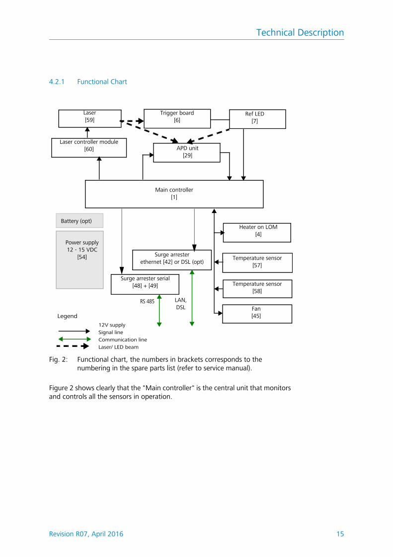
Fig. 2: Functional chart, the numbers in brackets corresponds to the numbering in the spare parts list (refer to service manual).
Figure 2 shows clearly that the "Main controller" is the central unit that monitors and controls all the sensors in operation.
Laser[59]
Laser controller module[60]
Main controller[1]
Power supply12 - 15 VDC
[54]
Trigger board[6]
APD unit[29]
LAN, DSL
Surge arrester ethernet [42] or DSL (opt)
Temperature sensor[57]
Temperature sensor[58]
Fan[45]
Surge arrester serial[48] + [49]
12V supply
Signal lineCommunication line
Laser/ LED beam
Legend
RS 485
Heater on LOM[4]
Ref LED[7]
Battery (opt)
Technical Description
16 Revision R07, April 2016
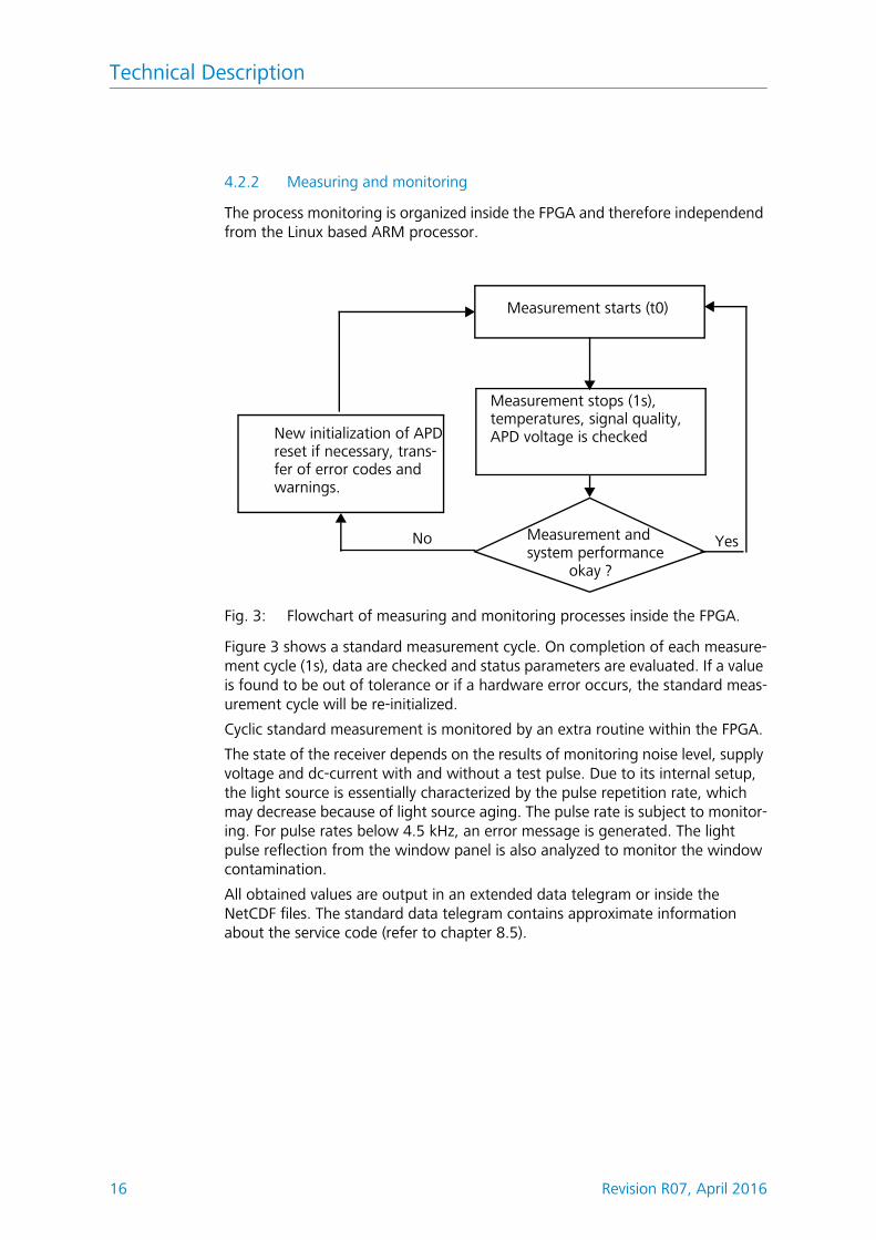
4.2.2 Measuring and monitoring
The process monitoring is organized inside the FPGA and therefore independend from the Linux based ARM processor.
Fig. 3: Flowchart of measuring and monitoring processes inside the FPGA.
Figure 3 shows a standard measurement cycle. On completion of each measure-ment cycle (1s), data are checked and status parameters are evaluated. If a value is found to be out of tolerance or if a hardware error occurs, the standard meas-urement cycle will be re-initialized.
Cyclic standard measurement is monitored by an extra routine within the FPGA.
The state of the receiver depends on the results of monitoring noise level, supply voltage and dc-current with and without a test pulse. Due to its internal setup, the light source is essentially characterized by the pulse repetition rate, which may decrease because of light source aging. The pulse rate is subject to monitor-ing. For pulse rates below 4.5 kHz, an error message is generated. The light pulse reflection from the window panel is also analyzed to monitor the window contamination.
All obtained values are output in an extended data telegram or inside the NetCDF files. The standard data telegram contains approximate information about the service code (refer to chapter 8.5).
Measurement starts (t0)
New initialization of APDreset if necessary, trans-
Measurement andsystem performance
No Yes
Measurement stops (1s), temperatures, signal quality,APD voltage is checked
okay ?
fer of error codes and warnings.
Transportation & Scope of Delivery
Revision R07, April 2016 17
5 Transportation & Scope of Delivery
CAUTIONDanger of damage!The CHM 15k may only be transported and moved with the help of suit-able lifting gear and an appropriate means of transportation.The CHM 15k may only be loaded and transported in packaged condition and in the transporting position (see Fig. 5).Inside its shipping container, the CHM 15k must be adequately protected against slipping, shock, stroke or other mechanical impacts.
The scope of delivery includes:l CHM 15k Cloud Height Meterl Drilling templatel Fastener components
4 S12 wallplug/ anchor (e.g. from Fischer)4 DIN 571-10 x 140-ZN screws4 ISO 7093-10.5-KST/PA washers4 ISO 7093-10.5-A2 washers
l User manual and device software
If requested by the customer, an adapter frame can be delivered together with the equipment to allow the CHM 15k to be screwed onto prepared fastening bolts. Angle adapters, e.g. for 15° are also available upon request.
Imperial units information: Spanner/ wrench size for 4x M10 screws: 18 mm or 7/16 BSF or 3/8 Wworth. Instead of M10 screw an imperial 3/8 or 25/64 might be used together with appropriate anchors.
Please contact G. Lufft GmbH for further technical details.
Operating state at the time of CHM 15k product delivery:
For further details on operating states, consult chapter 8.
Transfer mode 1 Automatic output of standard data telegram
Device code (device) 16
Baud rate 9,600
Duration of measurement 30 seconds
Installation
Revision R07, April 2016 19
6 Installation
CAUTIONThere is danger of mechanical damage!The owner/operator of the CHM 15k will be responsible for dimensioning and manufacturing a concrete base. This mounting base must be properly sized to withstand the lasting strain that is caused by the equipment's own weight and by external influences.
CAUTIONThere is danger of mechanical damage!The device must not be opened during work for setting up or starting up, in order to prevent the penetration of dirt or humidity. If opening becomes necessary, e.g. following a malfunction, work of this kind may only be performed by duly instructed personnel.
The CHM 15k Cloud Height Meter is assembled and fixed on a suitably sized concrete foundation.
Levelling screws are integrated with the bottom of the support legs to allow for vertical adjustment and, hence, vertical adjustment of the measuring unit.
6.1 Installing the CHM 15k
6.1.1 Preparatory Work
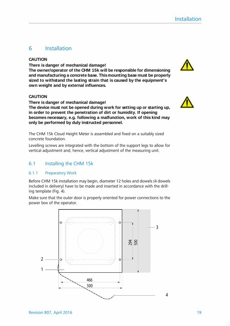
Before CHM 15k installation may begin, diameter 12 holes and dowels (4 dowels included in delivery) have to be made and inserted in accordance with the drill-ing template (Fig. 4).
Make sure that the outer door is properly oriented for power connections to the power box of the operator.
2
1
3
4
Installation
20 Revision R07, April 2016
Fig. 4: Drilling template
1 Drilling template
2 Holes (15 mm in diameter) for mech. attachment
3 Power supply port (for connection box)
4 Opening direction of outer door
6.1.2 Installation on the Mounting Base
CAUTIONThere is danger of accidents during installation work!The weight of the CHM 15k amounts to 70 kg. For this reason, at least two persons are required to assemble the Cloud Height Meter.
To install the CHMK 15k Cloud Height Meter, proceed as follows:
1. Unload the CHM 15k from its means of transportation, using appropriate lifting gear and place it down as near as possible to the designated installa-tion.
Fig. 5: The CHM 15k packaged and in transporting position
1 Packaging of wooden
2 Pallet
2. Remove packaging– Screw the side walls– Remove the sidewalls seperate
Installation
Revision R07, April 2016 21
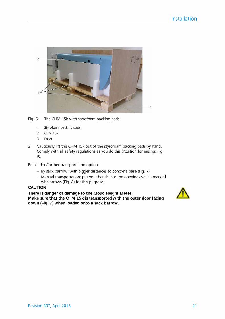
Fig. 6: The CHM 15k with styrofoam packing pads
1 Styrofoam packing pads
2 CHM 15k
3 Pallet
3. Cautiously lift the CHM 15k out of the styrofoam packing pads by hand. Comply with all safety regulations as you do this (Position for raising: Fig. 8).
Relocation/further transportation options:
– By sack barrow: with bigger distances to concrete base (Fig. 7)– Manual transportation: put your hands into the openings which marked
with arrows (Fig. 8) for this purposeCAUTIONThere is danger of damage to the Cloud Height Meter!Make sure that the CHM 15k is transported with the outer door facing down (Fig. 7) when loaded onto a sack barrow.
Installation
22 Revision R07, April 2016
Fig. 7: Transporting by sack barrow
Fig. 8: Position for raising
4. Place the CHM 15k in the mounting position (vertical) onto its concrete base. As you do this, pay attention to the outer door position in relation to the local power connection box (see Fig. 4).
5. Use the washers and screws (supplied) to pre-assemble the CHM 15k (see Fig. 9) so it is preliminarily fixed on its concrete base.
Installation
Revision R07, April 2016 23
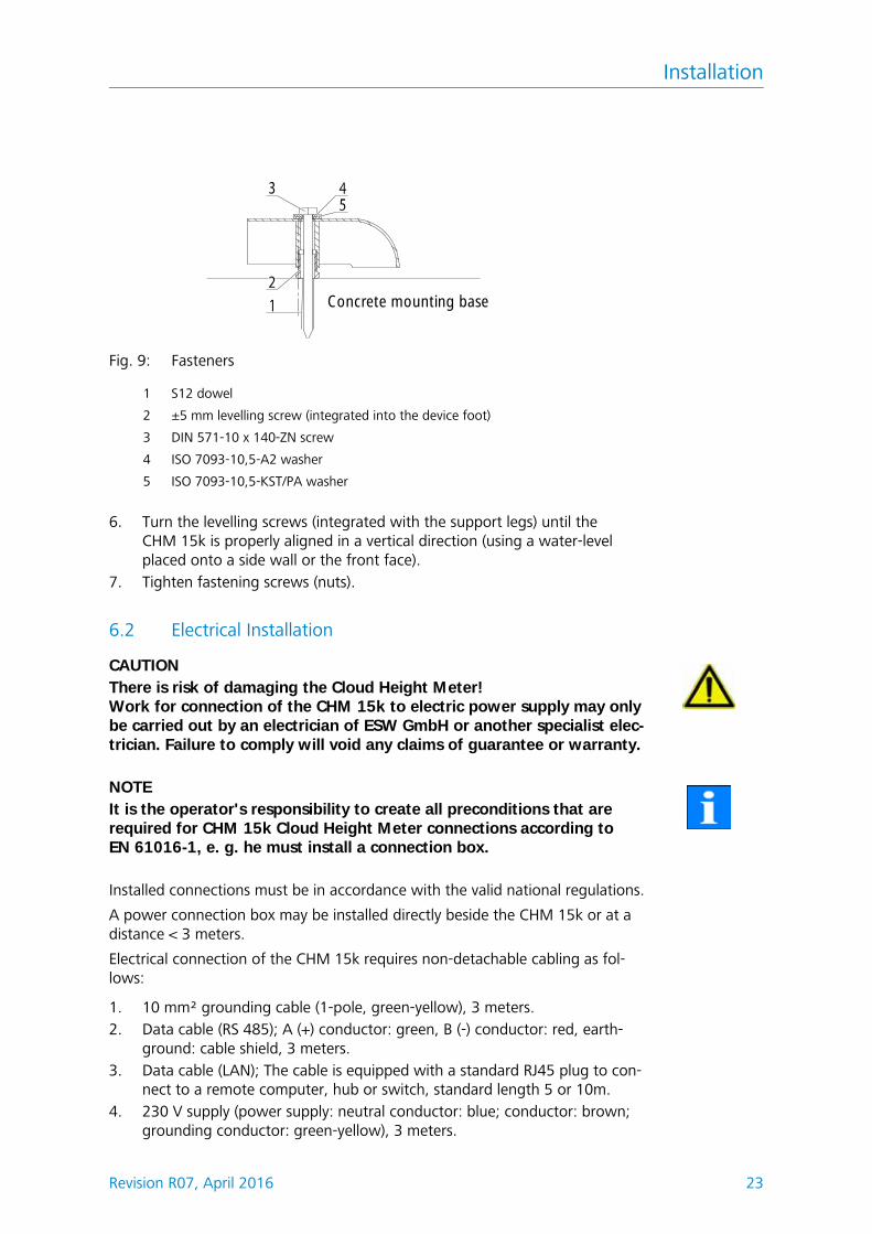
Fig. 9: Fasteners
1 S12 dowel
2 ±5 mm levelling screw (integrated into the device foot)
3 DIN 571-10 x 140-ZN screw
4 ISO 7093-10,5-A2 washer
5 ISO 7093-10,5-KST/PA washer
6. Turn the levelling screws (integrated with the support legs) until the CHM 15k is properly aligned in a vertical direction (using a water-level placed onto a side wall or the front face).
7. Tighten fastening screws (nuts).
6.2 Electrical Installation
CAUTIONThere is risk of damaging the Cloud Height Meter!Work for connection of the CHM 15k to electric power supply may only be carried out by an electrician of ESW GmbH or another specialist elec-trician. Failure to comply will void any claims of guarantee or warranty.
NOTEIt is the operator's responsibility to create all preconditions that are required for CHM 15k Cloud Height Meter connections according to EN 61016-1, e. g. he must install a connection box.
Installed connections must be in accordance with the valid national regulations.
A power connection box may be installed directly beside the CHM 15k or at a distance < 3 meters.
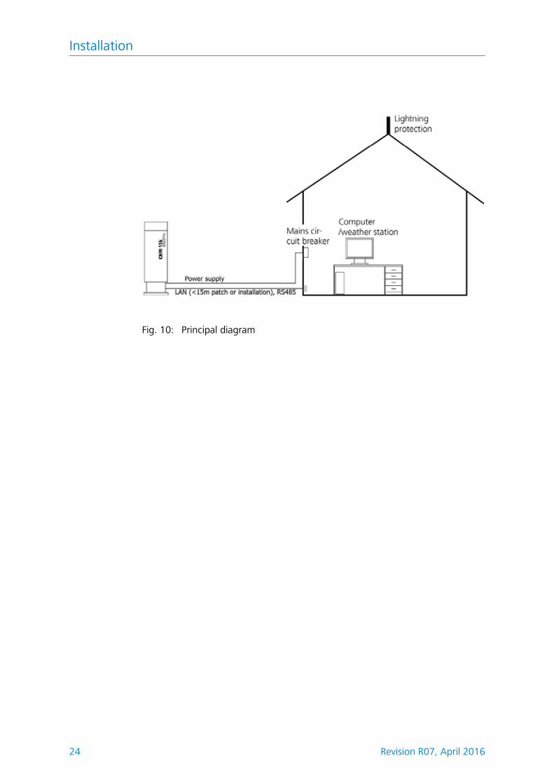
Electrical connection of the CHM 15k requires non-detachable cabling as fol-lows:
1. 10 mm² grounding cable (1-pole, green-yellow), 3 meters.2. Data cable (RS 485); A (+) conductor: green, B (-) conductor: red, earth-
ground: cable shield, 3 meters.3. Data cable (LAN); The cable is equipped with a standard RJ45 plug to con-
nect to a remote computer, hub or switch, standard length 5 or 10m.4. 230 V supply (power supply: neutral conductor: blue; conductor: brown;
grounding conductor: green-yellow), 3 meters.
Concrete mounting base
Installation
24 Revision R07, April 2016
Fig. 10: Principal diagram
Starting Up & Shutting Down
Revision R07, April 2016 25
7 Starting Up & Shutting Down
7.1 Starting Up with serial connection RS485
Preconditionsl The CHM 15k Cloud Height Meter has been installed in a conforming man-
ner.l The control cable (RS485), ground cable and power cable (230 V) are con-
nected.l For communication checks, a terminal program, e.g. a hyper terminal work-
ing under Windows is available. It has been configured for communication as follows:– Baud rate: 9,600– Data bits: 8– Parity: none– Stop bits: 1– Flow control: none
DANGERLaser radiation! There is danger of eye injury!Once power is on, the CHM 15k emits invisible laser radiation. Don't directly look into the laser beam. Under no circumstances may the laser beam be observed using optical instruments (field glasses).
Starting conditionsAfter the on-site mains circuit breaker has been turned into power-on position, the CHM 15k will start up by itself. It will be fully operational after a temperature adjustment phase of varying length. Depending on outdoor temperatures, this phase may last from a few minutes to one hour (at 40 °C below zero).
NOTEFollowing a short-time power failure (for a few seconds), no warming-up phase is required. The CHM 15k will be fit for use again after two min-utes.
Communication with the CHM 15k will be possible if a minimum temperature of 0 °C is reached in its inner space.
System state query via RS485Operating state of the CHM 15k at the time of delivery:
l Automatic output of standard data telegraml RS485 ID number 16l Baud rate 9,600l Measuring time: 30 seconds
For further detailed information about operating states, refer to chapter 8.
Starting Up & Shutting Down
26 Revision R07, April 2016
For testing of communication, use a
set<SPACE><RS485No>:Transfermode=0<CR><LF>command. It will switch to polling mode.
Working in this mode, you are able to test the following three types of telegram:l Standard data telegraml Extended data telegraml Raw data telegram
and make device settings as may be required. Chapter 8 describes available com-mands and their effects in detail.
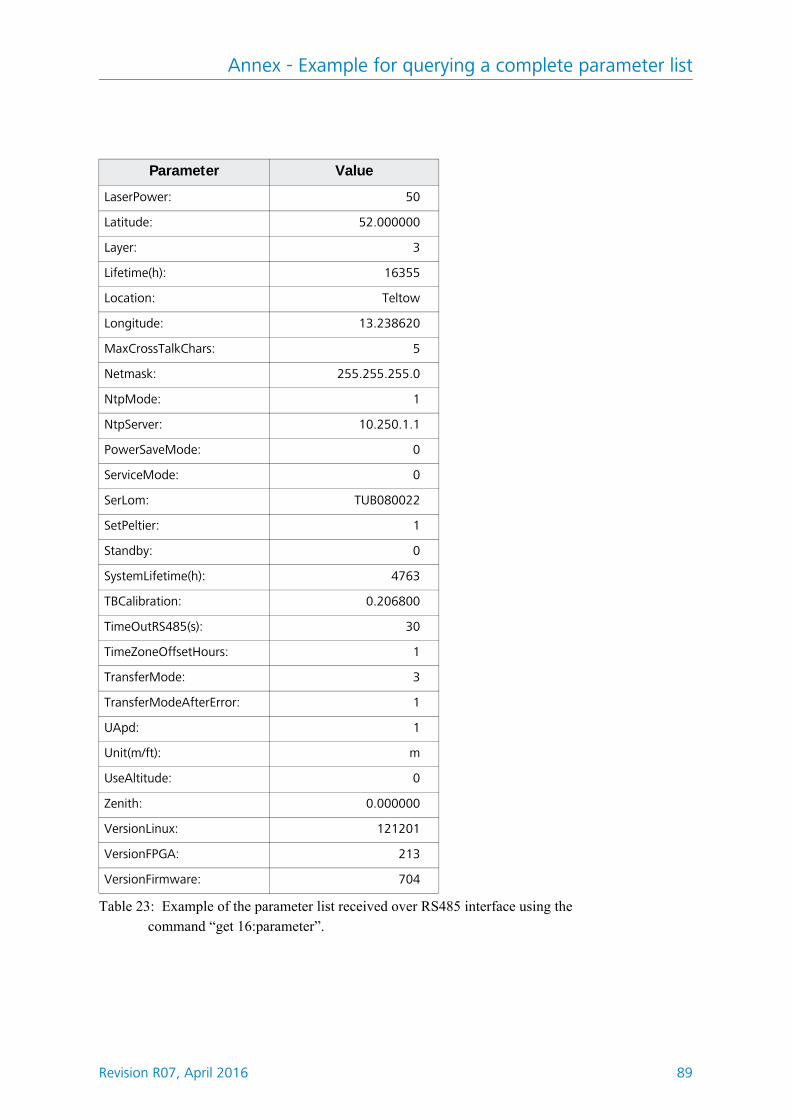
Table 2 shows the most important commands that are necessary to perform sim-ple function tests in routine mode.
On completion of simple function testing: of the CHM 15k:l continue to operate the CHM 15k in polling mode orl set it back to automatic transfer mode
set<SPACE><RS485No>:Transfermode=1<CR><LF>
Note: This command refers to automatic transfer mode.
NOTEPay special attention to the baud rate setting for RS485 bus operation. If you operate the system in raw data transfer mode, you should set the baud rate at least 19.200 Baud for a short transmission time of telegrams.
Command DescriptionReply
(shortened)
get<SPACE>16:L<CR><LF> Poll for extended data telegram
refer to chapter 8.3.4
set<SPACE>16:RNO=14<CR><LF> Changes RS485 number from 16 to 14
set 16:RNO=14
set<SPACE>16:Baud=4<CR><LF> Sets baud rate to 19,200 set 16:Baud=4
get<SPACE>16:Lifetime(h)<CR><LF> Queries laser operating time in hours
get 16:Lifetime(h)
Table 2: Essential commands for function testing (examples)
Starting Up & Shutting Down
Revision R07, April 2016 27
7.2 Starting up with LAN connection
Additionally or instead of the RS 485 connection a LAN connection (Ether-net) can be used. Precondition: LAN cable is connected (see chapter 6.2)
Configuration: 3 IP addresses are available at the same time for communication:
1. a pre-configured fixed service address to the CHM 15k Nimbus– 192.168.100.101, Subnet 255.255.255.0
2. DHCP server allocation (DHCP server required)3. user address + subnet + gateway ( Ssee chapter 8.7 for configuration with
LAN / WAN access to the instrument and chapter 8.1 and 8.2 if you config-ure these values using the RS485 interface)
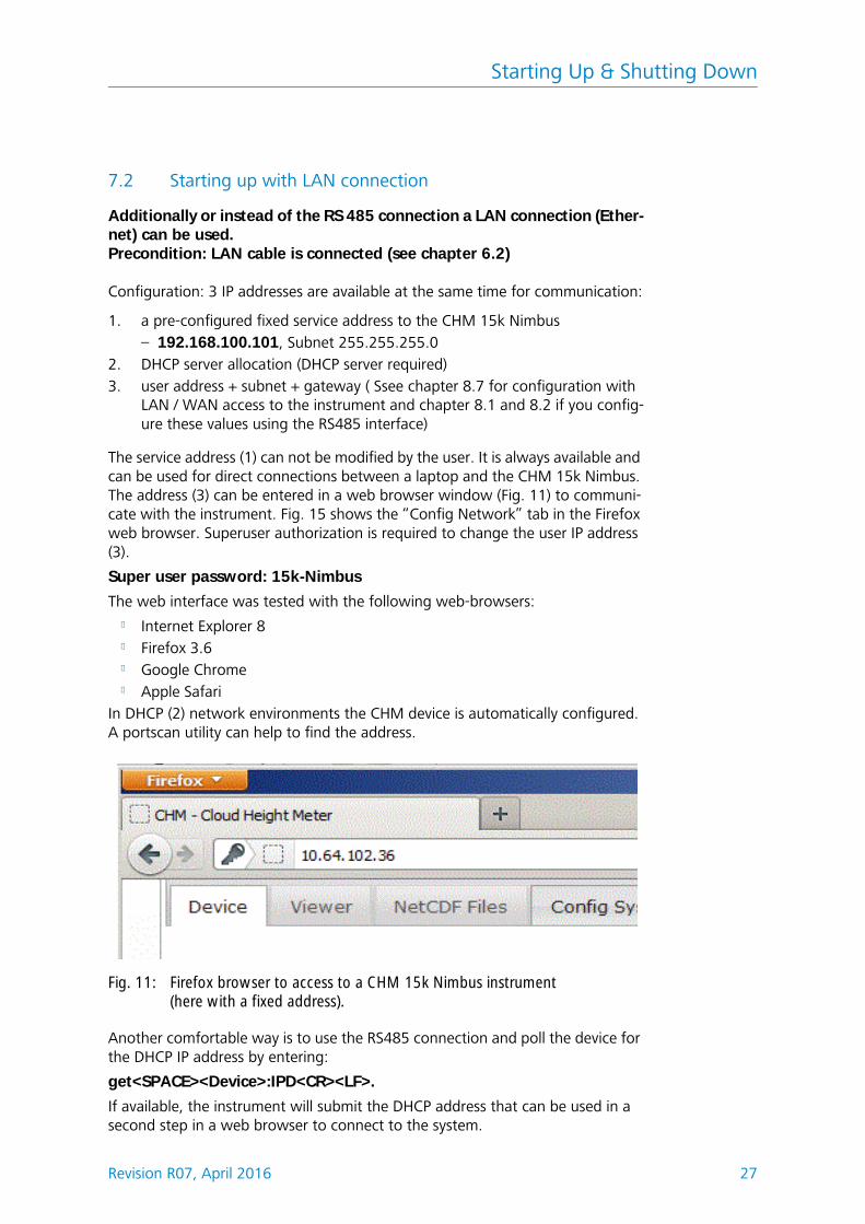
The service address (1) can not be modified by the user. It is always available and can be used for direct connections between a laptop and the CHM 15k Nimbus. The address (3) can be entered in a web browser window (Fig. 11) to communi-cate with the instrument. Fig. 15 shows the “Config Network” tab in the Firefox web browser. Superuser authorization is required to change the user IP address (3).
Super user password: 15k-Nimbus
The web interface was tested with the following web-browsers:l Internet Explorer 8l Firefox 3.6l Google Chromel Apple Safari
In DHCP (2) network environments the CHM device is automatically configured. A portscan utility can help to find the address.
Another comfortable way is to use the RS485 connection and poll the device for the DHCP IP address by entering:
get<SPACE><Device>:IPD<CR><LF>.
If available, the instrument will submit the DHCP address that can be used in a second step in a web browser to connect to the system.
Fig. 11: Firefox browser to access to a CHM 15k Nimbus instrument (here with a fixed address).
Starting Up & Shutting Down
28 Revision R07, April 2016
The user IP-address can be set or queried by the user via RS485 using the param-eter IPS instead of IPD, e.g.:
get<SPACE><Device>:IPS<CR><LF>
For further communication please contact G. Lufft GmbH for assistance.
7.3 Shutting Down
Advanced users shall power off the system carefully to avoid any data loss:
1. Users with software superuser privileges shall use the web interface: login in as superuser and press “SHUTDOWN SYSTEM” at the data transfer panel, the same command is available for the RS485 interface.
2. Service trained persons may also open the inner housing door and press the white “shut down” button at the main controller (check service manual for details)
Procedures (1) or (2) have the same effect. The Linux based system is powered down and measuring data are saved on the local SD Card.
3. Switch off the power supply.
To disassemble the CHM15k Cloud Height Meter and install it in another loca-tion, perform the sequence of working steps described in chapter 6.1.2 and chapter 6.2 in reverse order.
NOTEIn case of malfunction/faults, disconnect the CHM 15k from power supply (using the mains circuit breaker). Turn on power again after a short pause. If the problem persists, you should contact a qualified on-site ser-vice technician. If case of urgent problems, you should directly contact the service from Lufft.
7.4 Disposal
NOTEDisposal of the CHM 15k Cloud Height Meter must be in accordance with national regulations.
Communication RS485 & Ethernet
Revision R07, April 2016 29
8 Communication RS485 & Ethernet
The CHM 15k Nimbus supports two interfaces RS485 (section 8.2) and Ethernet (section 8.7) to communicate with the instrument. Both have the opportunity to transfer the measured values and to configure the instrument.
A web-interface is part of the system for the main communication (configura-tion) over the Ethernet interface. It can be accessed by many web browser inde-pendent from the operating system. The web-interface can also be used to download measured data manually, which are stored in daily NetCDF (section 8.4) files on a build in SD Card. An AFD (fto) service (section 8.8) is implemented in the system too, which allows the transfer of eg 5 min blocks of NetCDF data to any external ftp server.
For RS 485 communication a terminal software is required. For operating sys-tems running Microsoft Windows™ the terminal software “JO-DataClient” is supplied together with the equipment.
NOTEThe RS 485 half-dublex interface does not allow sending and receiving data on at the same time. Accordingly, the interface has its own auto-matic switching mechanism. This explains why you cannot send other commands (refer to chapter 8.1) when receiving a data telegram. Data telegrams are described in chapter 8.3.3 to 8.3.5. Incoming initial <STX> and end <EOT> character codes are indication of a running receive trans-mission session.
CAUTIONLoss of data!If you use query software other than “JO-DataClient”, make sure that it provides an internal function for automatic switching between transmit-ting and receiving mode. Otherwise, malfunctions may occur at the RS485 interface and cause loss of data.
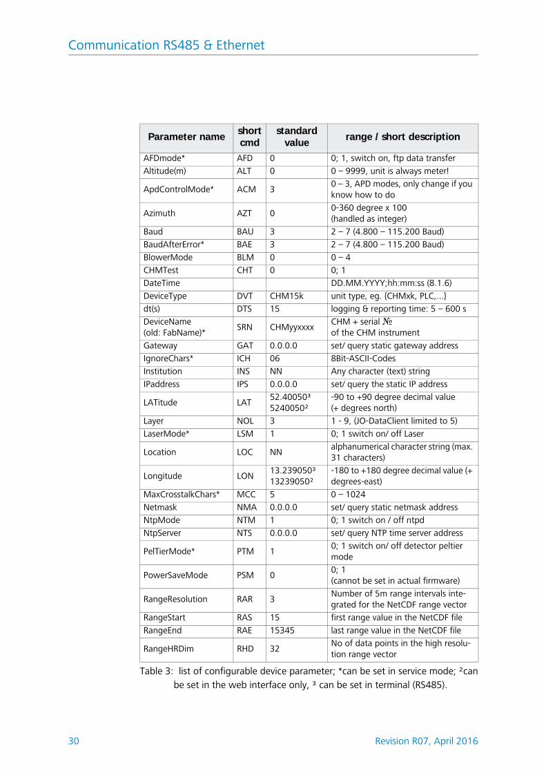
8.1 List of configurable instrument parameters
Table 3 contains the most important setting options. They will be explained in the following sections. For safety reasons and because they have a considerable influence on the way the CHM 15k functions, some options are only available if the ceilometer is set into a service mode(RS485) or superuser mode (Ethernet). Some additional parameters like the instrument name itself can be set only as service user using a Ethernet connection.
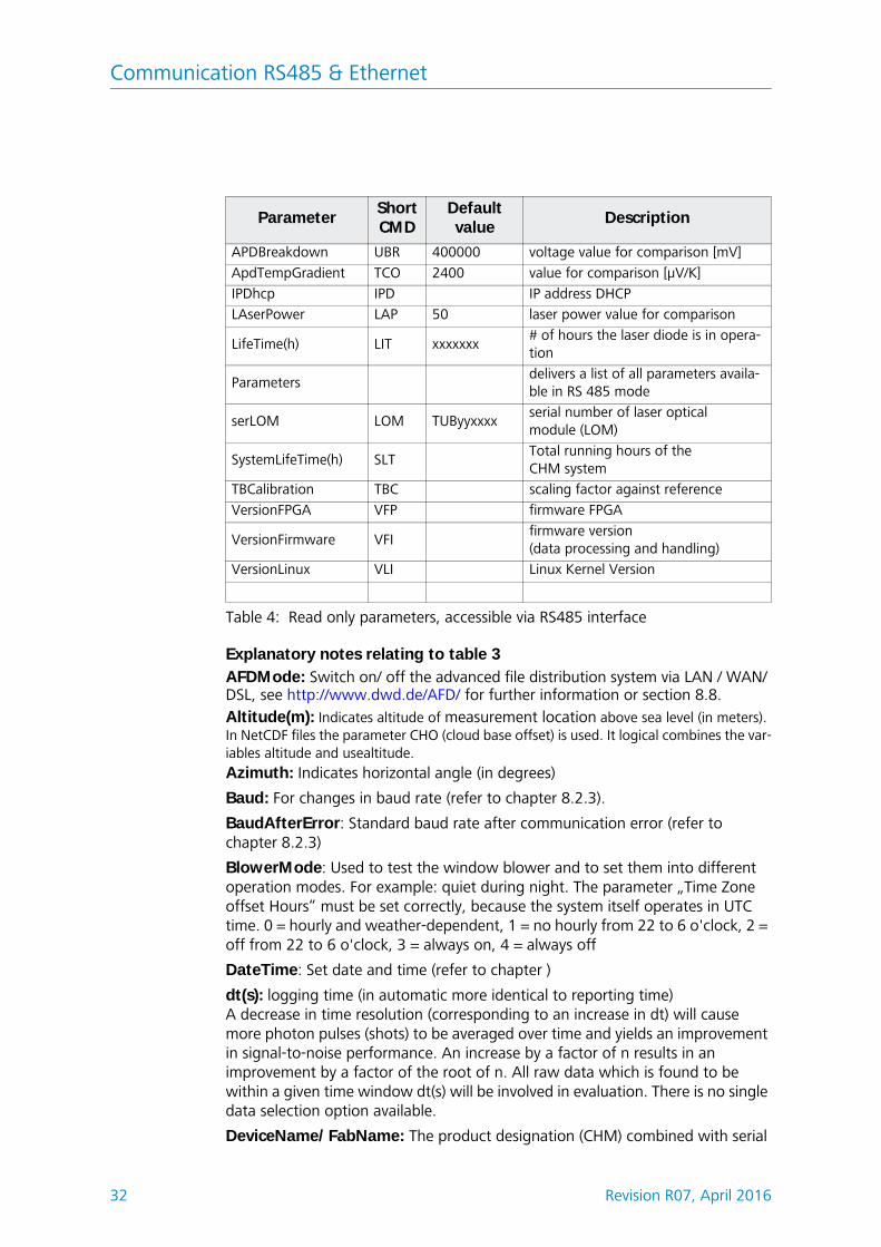
table 4 provides a list of additional read only parameters. These parameters are partly saved on the EEPROM mounted on the laser optical module (LOM). They have an impact on data evaluation and basic system settings. The tables are con-taining the permissible value range for each parameter together with the default value that is set at the time of product shipment and an indicator if service mode is required or not.
Communication RS485 & Ethernet
30 Revision R07, April 2016
Parameter nameshortcmd
standard value
range / short description
AFDmode* AFD 0 0; 1, switch on, ftp data transfer
Altitude(m) ALT 0 0 – 9999, unit is always meter!
ApdControlMode* ACM 30 – 3, APD modes, only change if you know how to do
Azimuth AZT 00-360 degree x 100(handled as integer)
NtpServer NTS 0.0.0.0 set/ query NTP time server address
PelTierMode* PTM 10; 1 switch on/ off detector peltier mode
PowerSaveMode PSM 00; 1(cannot be set in actual firmware)
RangeResolution RAR 3Number of 5m range intervals inte-grated for the NetCDF range vector
RangeStart RAS 15 first range value in the NetCDF file
RangeEnd RAE 15345 last range value in the NetCDF file
RangeHRDim RHD 32No of data points in the high resolu-tion range vector
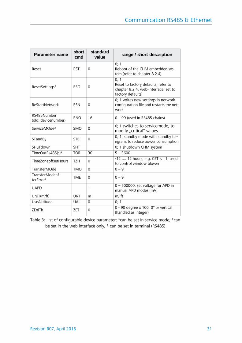
Table 3: list of configurable device parameter; *can be set in service mode; ²canbe set in the web interface only, ³ can be set in terminal (RS485).
Communication RS485 & Ethernet
Revision R07, April 2016 31
Reset RST 00; 1Reboot of the CHM embedded sys-tem (refer to chapter 8.2.4)
ResetSettings³ RSG 0
0; 1Reset to factory defaults, refer to chapter 8.2.4, web-interface: set to factory defaults)
ReStartNetwork RSN 00; 1 writes new settings in network configuration file and restarts the net-work
RS485Number(old: devicenumber)
RNO 16 0 – 99 (used in RS485 chains)
ServiceMOde³ SMO 00; 1 switches to servicemode, to modify „critical“ values.
STandBy STB 00; 1, standby mode with standby tel-egram, to reduce power consumption
SHuTdown SHT 0; 1 shutdown CHM system
TimeOutRs485(s)* TOR 30 5 – 3600
TimeZoneoffsetHours TZH 0-12 .... 12 hours, e.g. CET is +1, used to control window blower
TransferMOde TMO 0 0 – 9
TransferModeaf-terError*
TME 0 0 – 9
UAPD 10 – 500000, set voltage for APD in manual APD modes [mV]
UNiT(m/ft) UNT m m, ft
UseALtitude UAL 0 0; 1
ZEniTh ZET 00 - 90 degree x 100, 0° := vertical(handled as integer)
Parameter nameshortcmd
standard value
range / short description
Table 3: list of configurable device parameter; *can be set in service mode; ²canbe set in the web interface only, ³ can be set in terminal (RS485).
Communication RS485 & Ethernet
32 Revision R07, April 2016
Explanatory notes relating to table 3
AFDMode: Switch on/ off the advanced file distribution system via LAN / WAN/ DSL, see http://www.dwd.de/AFD/ for further information or section 8.8.Altitude(m): Indicates altitude of measurement location above sea level (in meters). In NetCDF files the parameter CHO (cloud base offset) is used. It logical combines the var-iables altitude and usealtitude. Azimuth: Indicates horizontal angle (in degrees)
Baud: For changes in baud rate (refer to chapter 8.2.3).
BaudAfterError: Standard baud rate after communication error (refer to chapter 8.2.3)
BlowerMode: Used to test the window blower and to set them into different operation modes. For example: quiet during night. The parameter „Time Zone offset Hours“ must be set correctly, because the system itself operates in UTC time. 0 = hourly and weather-dependent, 1 = no hourly from 22 to 6 o'clock, 2 = off from 22 to 6 o'clock, 3 = always on, 4 = always off
DateTime: Set date and time (refer to chapter )
dt(s): logging time (in automatic more identical to reporting time) A decrease in time resolution (corresponding to an increase in dt) will cause more photon pulses (shots) to be averaged over time and yields an improvement in signal-to-noise performance. An increase by a factor of n results in an improvement by a factor of the root of n. All raw data which is found to be within a given time window dt(s) will be involved in evaluation. There is no single data selection option available.
DeviceName/ FabName: The product designation (CHM) combined with serial
ParameterShortCMD
Default value
Description
APDBreakdown UBR 400000 voltage value for comparison [mV]
ApdTempGradient TCO 2400 value for comparison [μV/K]
IPDhcp IPD IP address DHCP
LAserPower LAP 50 laser power value for comparison
LifeTime(h) LIT xxxxxxx# of hours the laser diode is in opera-tion
Parametersdelivers a list of all parameters availa-ble in RS 485 mode
serLOM LOM TUByyxxxxserial number of laser optical module (LOM)
SystemLifeTime(h) SLTTotal running hours of the CHM system
TBCalibration TBC scaling factor against reference
VersionFPGA VFP firmware FPGA
VersionFirmware VFIfirmware version(data processing and handling)
VersionLinux VLI Linux Kernel Version
Table 4: Read only parameters, accessible via RS485 interface
Communication RS485 & Ethernet
Revision R07, April 2016 33
number of a given device, e.g. CHM060001.
IgnoreChars: Variable contains 8Bit-ASCII-codes will be ignored by the CHM 15k. The ASCII-codes have to coded as 2 character HEX-code, e.g. “06” corresponds to <ack>. Only HEX-codes will be evaluated!
Institution: The name of the institution or company
Lasermode:
LaserPower: Laser Power in mW
Latitude: The latitude of a given location, in decimal numbers.
Sample value for Berlin: 52.51833 (corresponds 52° 31' 6'' N)
Layer (Number of Layer): No. of cloud layers displayed in extended telegram and NetCDF file
Layer: set the number of layers in the cloud telegram.
Lifetime(h): For querying of operating counter state of the laser lifetime.
Location: Set/ query the location, where the instrument is used. The name is restricted
Longitude: The longitude of a given location, in decimal numbers, where east-erly is defined as positive orientation.
Sample value for Berlin: 13.40833 (corresponds to 13° 24' 30'' E)
MaxCrossTalkChars: Sets a Number of characters the CHM 15k will ignore within “TimeOutRS485(s)” if they are receives in a fragmentary string, which may be a query not ended with <EOT> (04 HEX), <CR> (0D HEX), <LF> (0A HEX). The parameter is included to prevent the ceilometer to fall back in its standard baud rate caused by noise on unstable communication lines.
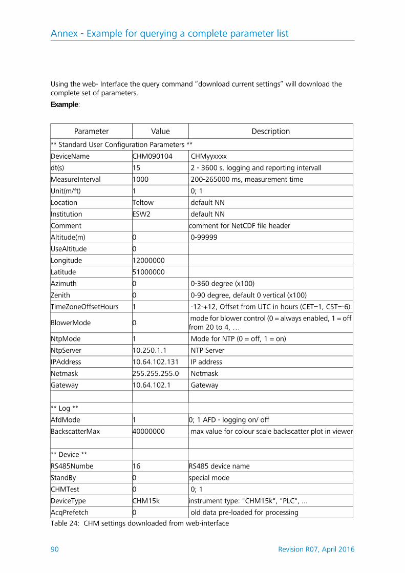
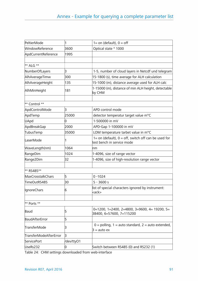
Parameters: For querying of a complete parameter list (see Annex B for details)
RS485Number: Designates the identification number in a bus system, which is required to address a given device via a data port.
Standby: Turns off laser, heater and blower
TimeOutRS485(s): Set time interval within MaxCrossTalkChars and BaudAfterError is reacting (standard 30s).
TransferMode: Refer to chapter 8.3.1 to 8.3.5.
Unit(m/ft): sets dimensions in meters (m) or feet (ft).
UseAltitude: Adds Altitude(m) to data output string.If a value of e.g. 60 m is specified for Altitude, the output value for a given cloud base will increase by 60 m.
Zenith: Indicates vertical angle (in degrees), the sky condition algorithm (SCA) is using this angle to calculate the real altitude of cloud bases against ground level.
8.2 Instrument Configuration using RS 485 interface
The user can change settings via the RS485 interface for:l control of the measuring processl configuration of the communication interfaces
Communication RS485 & Ethernet
34 Revision R07, April 2016
8.2.1 Reading a parameter
To read a parameter, you must trigger a command:
get<SPACE><RS485No>:<ParameterName><CR><LF>If <ParameterName> is found to contain a valid designation according to table 3 or table 4, its value will be output as part of
If the instrument serial number (Devicename) was preset to CHM060003, you may query the name, using the short command
get 16:DVN<CR><LF>The response to this query may look like this:
<STX>get 16:DeviceName=CHM15kd01;2B<CR><LF><EOT>.
where each of <STX>, <CR>, <LF> and <EOT> stand for one byte with hexadeci-mal codes 02, 0D, 0A and 04 in this same order. The value 3F represents the checksum of the two's complement formed over the whole response line, excluding the two characters (3F) themselves, in accordance with the established protocol response format (refer to chapter 8.3.3 to 8.3.5).
Communication RS485 & Ethernet
Revision R07, April 2016 35
8.2.2 Setting a parameter
A command line like
set<SPACE><RS485No>:<ParameterName>=<Value><CR><LF>can change a desired configuration parameter. The successful completion of a change in parameter setting is reported via:
<STX>set<SPACE><RS485No>:<ParameterName>=<Value>;<ASCII-Two’s complement><CR><LF><EOT>If <Value> is found to be within permissible limits, the newly set value <NewValue> meets this requirement. If an entry is found to be above the upper limit or below the lower limit, the permitted maximum or minimum value will be applied instead. With alphanumerical entries the default value will be applied as <Value>.
Example:
Following a command,
set 16:Unit(m/ft)=ft<CR><LF>or in short formset 16:UNT=ft<CR><LF>all range data in a telegram will be indicated in feet (ft) instead of meter (m). Since Unit(m/ft) provides a switching option,
<STX>set 16:Unit(m/ft)=ft;2A<CR><LF><EOT>is output for confirmation. 2A is the checksum value of the response line.
8.2.3 Change in Baud Rate
Changes in the baud rate are a special setting option. To make a change, pro-ceed as described in chapter 8.2.2. For example, by triggering a
set<SPACE>16:Baud=4<CR><LF>command, you will set baud rate “4”, i.e. 19,200 bits per second, for RS485No 16. Table 5 shows all baud rate numbers and their assigned baud rate values.
Immediately on triggering a set command of this type, the interface will be set to
Baud rate no. Baud rate [bits/s]
(0) (1,200)
(1) (2,400)
2 4,800
3 9,600
4 19,200
5 38,400
6 57,600
7 115,200
Table 5: Baud-rate-number-to-baud-rate assignments. Baud rates 0;1 are notspecified within the time limits.
Communication RS485 & Ethernet
36 Revision R07, April 2016
the new baud rate. In the event of a false baud rate setting with consequential communication errors, it is not possible to reverse this setting as usual because of failure to establish normal communication. It will be reset to the default baud rate specified by parameter BaudAfterError after 30 seconds, which is the standard value of TimeOutRS485(s). The standard value of BaudAfterError is 3 (refer to chapter Table 3:) which means 9,600 bits per second. If this baud rate still proves too high, a different desired baud rate can be set as the default rate before product shipment or by service personnel.
8.2.4 Reboot of embedded linux system/ reset to factory settings
By triggering a
set<SPACE>16:Reset=1<CR><LF>command, the build in processor board is instructed to immediately perform a reboot.A restart procedure takes less than a minute. Before or unless it has finished, communication with the CHM 15k is not possible. The same applies to continu-ously ongoing telegram outputs.
With a
set<SPACE>16:ResetSettings=1<CR><LF>command you can restore all parameters to their factory settings.
8.2.5 Changing the logging time dt(s), date & time
set<SPACE><RS485No>:dt(s)=30<CR><LF>
The logging and reporting time is set to 30s. The internal measurement time is always set to 1s. The logging and reporting time must be multiple of one sec-ond.
With the help of
set<SPACE>16:DateTime=DD.MM.YYYY;hh:mm:ss<CR><LF>you can switch the date and time settings of the internal processing unit, where DD means day, MM month, YYYY year, hh hours, mm minutes and ss seconds, referenced to GMT zone (Greenwich Mean Time).
Example:
set 16:DateTime=13.04.2006;17:22:46<CR><LF>will set 13th April 2006 as the date and 17:22:46 GMT as the exact time.
The terminal software JO-DataClient has a build in update function for the time called „–utcupdaterate <hours>“ (chapter 11.10). If the ceilometer is connected to a WAN or LAN and the NTP option is active, time settings over the serial inter-faces shall be avoided.
8.3 Data Queries RS485
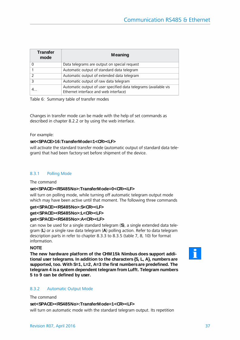
At any time during operation, the CHM 15k is in one of the following transfer modes as shown in table 6.
Communication RS485 & Ethernet
Revision R07, April 2016 37
Changes in transfer mode can be made with the help of set commands as described in chapter 8.2.2 or by using the web interface.
For example:
set<SPACE>16:TransferMode=1<CR><LF>will activate the standard transfer mode (automatic output of standard data tele-gram) that had been factory-set before shipment of the device.
8.3.1 Polling Mode
The command
set<SPACE><RS485No>:TransferMode=0<CR><LF>will turn on polling mode, while turning off automatic telegram output mode which may have been active until that moment. The following three commands
get<SPACE><RS485No>:S<CR><LF>get<SPACE><RS485No>:L<CR><LF>get<SPACE><RS485No>:A<CR><LF>can now be used for a single standard telegram (S), a single extended data tele-gram (L) or a single raw data telegram (A) polling action. Refer to data telegram description parts in refer to chapter 8.3.3 to 8.3.5 (table 7, 8, 10) for format information.
NOTEThe new hardware platform of the CHM15k Nimbus does support addi-tional user telegrams. In addition to the characters {S, L, A}, numbers are supported, too. With S=1, L=2, A=3 the first numbers are predefined. The telegram 4 is a system dependent telegram from Lufft. Telegram numbers 5 to 9 can be defined by user.
8.3.2 Automatic Output Mode
The command
set<SPACE><RS485No>:TransferMode=1<CR><LF>will turn on automatic mode with the standard telegram output. Its repetition
Transfer mode
Meaning
0 Data telegrams are output on special request
1 Automatic output of standard data telegram
2 Automatic output of extended data telegram
3 Automatic output of raw data telegram
4...Automatic output of user specified data telegrams (available vis Ethernet interface and web interface)
Table 6: Summary table of transfer modes
Communication RS485 & Ethernet
38 Revision R07, April 2016
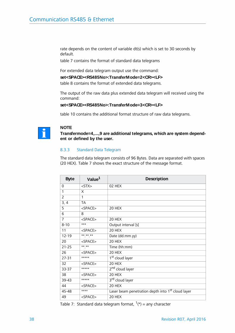
rate depends on the content of variable dt(s) which is set to 30 seconds by default.
table 7 contains the format of standard data telegrams
For extended data telegram output use the command:
set<SPACE><RS485No>:TransferMode=2<CR><LF>table 8 contains the format of extended data telegrams.
The output of the raw data plus extended data telegram will received using the command:
set<SPACE><RS485No>:TransferMode=3<CR><LF>
table 10 contains the additional format structure of raw data telegrams.
NOTETransfermode=4,...,9 are additional telegrams, which are system depend-ent or defined by the user.
8.3.3 Standard Data Telegram
The standard data telegram consists of 96 Bytes. Data are separated with spaces (20 HEX). Table 7 shows the exact structure of the message format.
Byte Value1 Description
0 <STX> 02 HEX
1 X
2 1
3, 4 TA
5 <SPACE> 20 HEX
6 8
7 <SPACE> 20 HEX
8-10 *** Output interval [s]
11 <SPACE> 20 HEX
12-19 **.**.** Date (dd.mm.yy)
20 <SPACE> 20 HEX
21-25 **.** Time (hh:mm)
26 <SPACE> 20 HEX
27-31 ***** 1st cloud layer
32 <SPACE> 20 HEX
33-37 ***** 2nd cloud layer
38 <SPACE> 20 HEX
39-43 ***** 3rd cloud layer
44 <SPACE> 20 HEX
45-48 **** Laser beam penetration depth into 1st cloud layer
49 <SPACE> 20 HEX
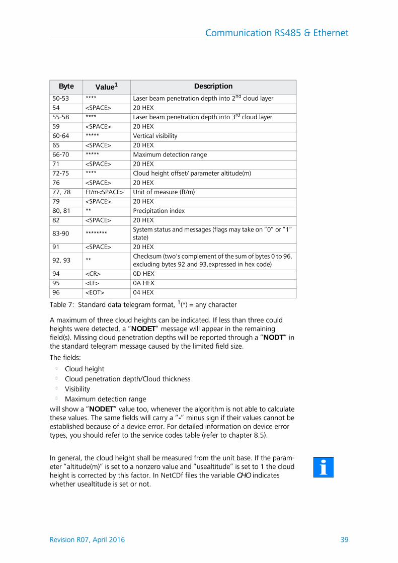
Table 7: Standard data telegram format, 1(*) = any character
Communication RS485 & Ethernet
Revision R07, April 2016 39
A maximum of three cloud heights can be indicated. If less than three could heights were detected, a “NODET” message will appear in the remaining field(s). Missing cloud penetration depths will be reported through a “NODT” in the standard telegram message caused by the limited field size.
The fields:l Cloud heightl Cloud penetration depth/Cloud thicknessl Visibilityl Maximum detection range
will show a “NODET” value too, whenever the algorithm is not able to calculate these values. The same fields will carry a “-” minus sign if their values cannot be established because of a device error. For detailed information on device error types, you should refer to the service codes table (refer to chapter 8.5).
In general, the cloud height shall be measured from the unit base. If the param-eter “altitude(m)” is set to a nonzero value and “usealtitude” is set to 1 the cloud height is corrected by this factor. In NetCDf files the variable CHO indicates whether usealtitude is set or not.
50-53 **** Laser beam penetration depth into 2nd cloud layer
54 <SPACE> 20 HEX
55-58 **** Laser beam penetration depth into 3rd cloud layer
83-90 ********System status and messages (flags may take on “0” or “1” state)
91 <SPACE> 20 HEX
92, 93 **Checksum (two's complement of the sum of bytes 0 to 96, excluding bytes 92 and 93,expressed in hex code)
94 <CR> 0D HEX
95 <LF> 0A HEX
96 <EOT> 04 HEX
Byte Value1 Description
Table 7: Standard data telegram format, 1(*) = any character
Communication RS485 & Ethernet
40 Revision R07, April 2016
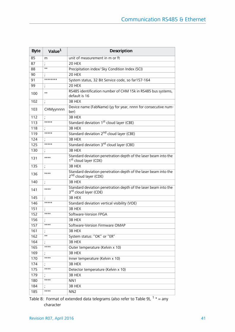
8.3.4 Extended Data Telegram
The extended data telegram consists of 240 Bytes. Semicolon (3B HEX) replaces space (20 HEX) as delimiter for extended data telegrams. Table 7 shows details about the telegram structure. The telegram size is different if the number of cloud layers “layer” has been changed.
Byte Value1 Description
0 <STX> 20 HEX
1 X
2 1
3 TA
5 ; 20 HEX
6 8
7 ; 20 HEX
8 *** Output interval [s]
11 ; 20 HEX
12 **.**.** Date (dd.mm.yy)
20 ; 20 HEX
21 **.**.** Time; Note modification, as of now (hh:mm:ss)
29 ; 20 HEX
30 * Numbers of layer
31 ;
32 ***** 1st Cloud layer (CBH)
37 ; 20 HEX
38 ***** 2nd Cloud layer (CBH)
43 ; 20 HEX
44 ***** 3rd Cloud layer (CBH)
49 ; 20 HEX
50 *****Penetration depth of the laser beam into the 1st cloud layer (CPD), Note: extension to 5 digit
55 ; 20 HEX
56 *****Penetration depth of the laser beam into the 2nd cloud layer
(CPD), Note: extension to 5 digit
61 ; 20 HEX
62 *****Penetration depth of the laser beam into the 3rd cloud layer
(CPD), Note: extension to 5 digit
67 ; 20 HEX
68 ***** Vertical visibility (VOR)
73 ; 20 HEX
74 ***** Max. detection range (MXD)
79 ; 20 HEX
80 **** Cloud height-Offset / altitude(m)
84 ; 20 HEX
Table 8: Format of extended data telegrams (also refer to Table 9), 1 * = any character
Communication RS485 & Ethernet
Revision R07, April 2016 41
85 m unit of measurement in m or ft
87 ; 20 HEX
88 ** Precipitation index/ Sky Condition Index (SCI)
90 ; 20 HEX
91 ******** System status, 32 Bit Service code, so far157-164
99 ; 20 HEX
100 **RS485 identification number of CHM 15k in RS485 bus systems, default is 16
102 ; 3B HEX
103 CHMyynnnnDevice name (FabName) (yy for year, nnnn for consecutive num-ber)
112 ; 3B HEX
113 ***** Standard deviation 1st cloud layer (CBE)
118 ; 3B HEX
119 ***** Standard deviation 2nd cloud layer (CBE)
124 ; 3B HEX
125 ***** Standard deviation 3rd cloud layer (CBE)
130 ; 3B HEX
131 ****Standard deviation penetration depth of the laser beam into the 1st cloud layer (CDE)
135 ; 3B HEX
136 ****Standard deviation penetration depth of the laser beam into the 2nd cloud layer (CDE)
140 ; 3B HEX
141 ****Standard deviation penetration depth of the laser beam into the 3rd cloud layer (CDE)
145 ; 3B HEX
146 ***** Standard deviation vertical visibility (VOE)
151 ; 3B HEX
152 **** Software-Version FPGA
156 ; 3B HEX
157 **** Software-Version Firmware OMAP
161 ; 3B HEX
162 ** System status: “OK” or “ER“
164 ; 3B HEX
165 **** Outer temperature (Kelvin x 10)
169 ; 3B HEX
170 **** Inner temperature (Kelvin x 10)
174 ; 3B HEX
175 **** Detector temperature (Kelvin x 10)
179 ; 3B HEX
180 **** NN1
184 ; 3B HEX
185 **** NN2
Byte Value1 Description
Table 8: Format of extended data telegrams (also refer to Table 9), 1 * = any character
Communication RS485 & Ethernet
42 Revision R07, April 2016
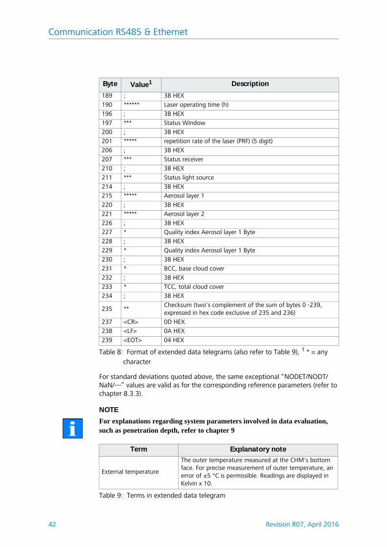
For standard deviations quoted above, the same exceptional “NODET/NODT/NaN/---” values are valid as for the corresponding reference parameters (refer to chapter 8.3.3).
NOTE
For explanations regarding system parameters involved in data evaluation, such as penetration depth, refer to chapter 9
189 ; 3B HEX
190 ****** Laser operating time (h)
196 ; 3B HEX
197 *** Status Window
200 ; 3B HEX
201 ***** repetition rate of the laser (PRF) (5 digit)
206 ; 3B HEX
207 *** Status receiver
210 ; 3B HEX
211 *** Status light source
214 ; 3B HEX
215 ***** Aerosol layer 1
220 ; 3B HEX
221 ***** Aerosol layer 2
226 ; 3B HEX
227 * Quality index Aerosol layer 1 Byte
228 ; 3B HEX
229 * Quality index Aerosol layer 1 Byte
230 ; 3B HEX
231 * BCC, base cloud cover
232 ; 3B HEX
233 * TCC, total cloud cover
234 ; 3B HEX
235 **Checksum (two's complement of the sum of bytes 0 -239, expressed in hex code exclusive of 235 and 236)
237 <CR> 0D HEX
238 <LF> 0A HEX
239 <EOT> 04 HEX
Byte Value1 Description
Table 8: Format of extended data telegrams (also refer to Table 9), 1 * = any character
Term Explanatory note
External temperature
The outer temperature measured at the CHM's bottom face. For precise measurement of outer temperature, an error of ±5 °C is permissible. Readings are displayed in Kelvin x 10.
Table 9: Terms in extended data telegram
Communication RS485 & Ethernet
Revision R07, April 2016 43
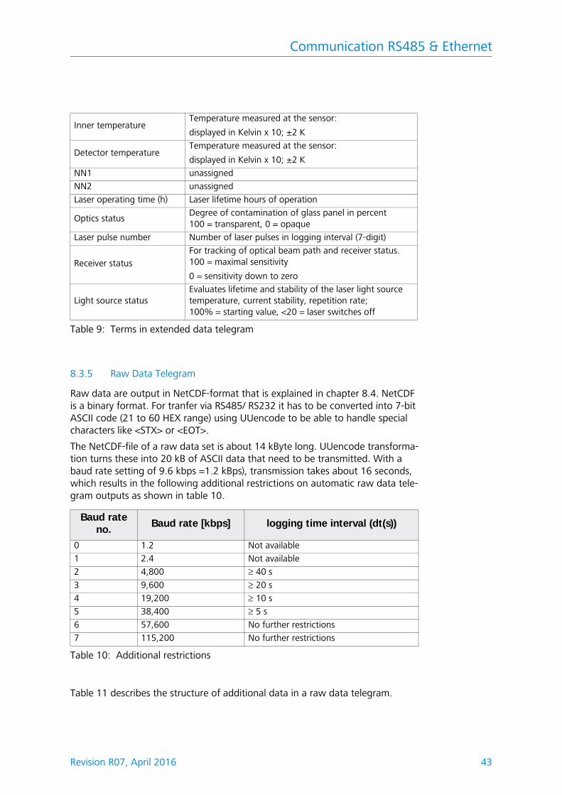
8.3.5 Raw Data Telegram
Raw data are output in NetCDF-format that is explained in chapter 8.4. NetCDF is a binary format. For tranfer via RS485/ RS232 it has to be converted into 7-bit ASCII code (21 to 60 HEX range) using UUencode to be able to handle special characters like <STX> or <EOT>.
The NetCDF-file of a raw data set is about 14 kByte long. UUencode transforma-tion turns these into 20 kB of ASCII data that need to be transmitted. With a baud rate setting of 9.6 kbps =1.2 kBps), transmission takes about 16 seconds, which results in the following additional restrictions on automatic raw data tele-gram outputs as shown in table 10.
Table 11 describes the structure of additional data in a raw data telegram.
Inner temperatureTemperature measured at the sensor:
displayed in Kelvin x 10; ±2 K
Detector temperatureTemperature measured at the sensor:
displayed in Kelvin x 10; ±2 K
NN1 unassigned
NN2 unassigned
Laser operating time (h) Laser lifetime hours of operation
Optics statusDegree of contamination of glass panel in percent100 = transparent, 0 = opaque
Laser pulse number Number of laser pulses in logging interval (7-digit)
Receiver statusFor tracking of optical beam path and receiver status.100 = maximal sensitivity
0 = sensitivity down to zero
Light source statusEvaluates lifetime and stability of the laser light source temperature, current stability, repetition rate; 100% = starting value, <20 = laser switches off
Baud rate no.
Baud rate [kbps] logging time interval (dt(s))
0 1.2 Not available
1 2.4 Not available
2 4,800 40 s
3 9,600 20 s
4 19,200 10 s
5 38,400 5 s
6 57,600 No further restrictions
7 115,200 No further restrictions
Table 10: Additional restrictions
Table 9: Terms in extended data telegram
Communication RS485 & Ethernet
44 Revision R07, April 2016
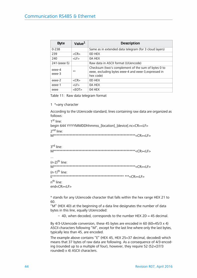
1 *=any character
According to the UUencode standard, lines containing raw data are organized as follows:
* stands for any UUencode character that falls within the hex range HEX 21 to 60.“M” (HEX 4D) at the beginning of a data line designates the number of data bytes in this line, equally UUencoded:
– 4D, when decoded, corresponds to the number HEX 2D = 45 decimal.
By 4/3-UUencode conversion, these 45 bytes are encoded in 60 (60=45/3 x 4) ASCII characters following “M”, except for the last line where only the last bytes, typically less than 45, are encoded.
The example above contains “E” (HEX 45, HEX 25=37 decimal, decoded) which means that 37 bytes of raw data are following. As a consequence of 4/3-encod-ing (rounded up to a multiple of four), however, they require 52 (52=(37/3 rounded) x 4) ASCII characters.
Byte Value1 Description
0-238 Same as in extended data telegram (for 3 cloud layers)
239 <CR> 0D HEX
240 <LF> 0A HEX
241-(eeee-5) Raw data in ASCII format (UUencode)
eeee-4eeee-3
**Checksum (two's complement of the sum of bytes 0 to eeee, excluding bytes eeee-4 and eeee-3,expressed inhex code)
eeee-2 <CR> 0D HEX
eeee-1 <LF> 0A HEX
eeee <EOT> 04 HEX
Table 11: Raw data telegram format
Communication RS485 & Ethernet
Revision R07, April 2016 45
The last line with “end” marks the termination of UUencode data.
An example of a file name in line 1
YYYYMMDDhhmmss_ [location]_[Device].ncis 20060331123730_Jena_CHM06003.nc (also refer to chapter 8.4.3).
which means:
– CHM060003 fabrication number in Jena, data of 31st March 2006,at 12:37:30.
If the device e. g. by means of an angle adapter placed obliquely, so does in line 1 the file name changes as follows:
YYYYMMDDhhmmss_ [location]_[zenith]_[Device].nc
In [zenith], the appropriate number of degrees is entered, for example 15°.
8.3.6 User configured data telegrams
The structure of data telegrams are defined in a file called “telegram.xml”. It can be downloaded and modified using the web interface in the superuser or service user mode.
Communication RS485 & Ethernet
46 Revision R07, April 2016
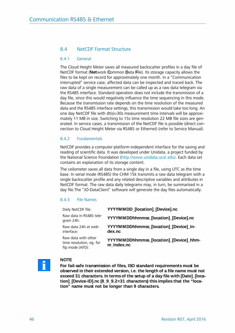
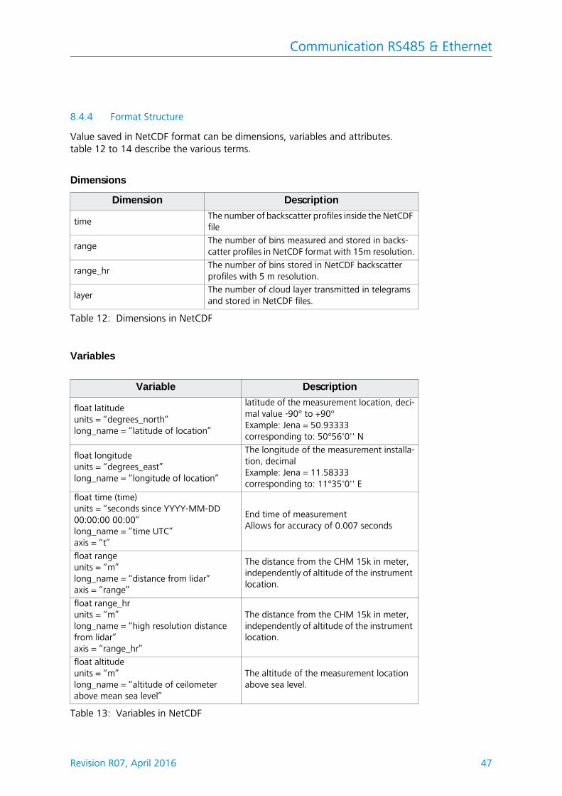
8.4 NetCDF Format Structure
8.4.1 General
The Cloud Height Meter saves all measured backscatter profiles in a day file of NetCDF format (Network Common Data File). Its storage capacity allows the files to be kept on record for approximately one month. In a “Communication interrupted” service case, affected data can be inspected and traced back. The raw data of a single measurement can be called up as a raw data telegram via the RS485 interface. Standard operation does not include the transmission of a day file, since this would negatively influence the time sequencing in this mode. Because the transmission rate depends on the time resolution of the measured data and the RS485 interface settings, this transmission would take too long. An one day NetCDF file with dt(s)=30s measurement time intervals will be approxi-mately 11 MB in size. Switching to 15s time resolution 22 MB file sizes are gen-erated. In service cases, a transmission of the NetCDF file is possible (direct con-nection to Cloud Height Meter via RS485 or Ethernet) (refer to Service Manual).
8.4.2 Fundamentals
NetCDF provides a computer-platform-independent interface for the saving and reading of scientific data. It was developed under Unidata, a project funded by the National Science Foundation (http://www.unidata.ucar.edu). Each data set contains an explanation of its storage content.
The ceilometer saves all data from a single day in a file, using UTC as the time base. In serial mode (RS485) the CHM 15k transmits a raw data telegram with a single backscatter profile and any related descriptive variables and attributes in NetCDF format. The raw data daily telegrams may, in turn, be summarised in a day file.The “JO-DataClient” software will generate the day files automatically.
8.4.3 File Names
NOTEFor fail-safe transmission of files, ISO standard requirements must be observed in their extended version, i.e. the length of a file name must not exceed 31 characters. In terms of the setup of a day file with [Date]_[loca-tion]_[Device-ID].nc (8_9_9.2=31 characters) this implies that the “loca-tion” name must not be longer than 9 characters.
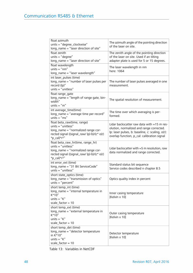
int laser_pulses (time)long_name = “number of laser pulses per record (lp)”units = “unitless”
The number of laser pulses averaged in one measurement.
float range_gatelong_name = “length of range gate, bin-width”units = “m”
The spatial resolution of measurement.
int average_time(time)long_name = “average time per record”units = “ms”
The time over which averaging is per-formed.
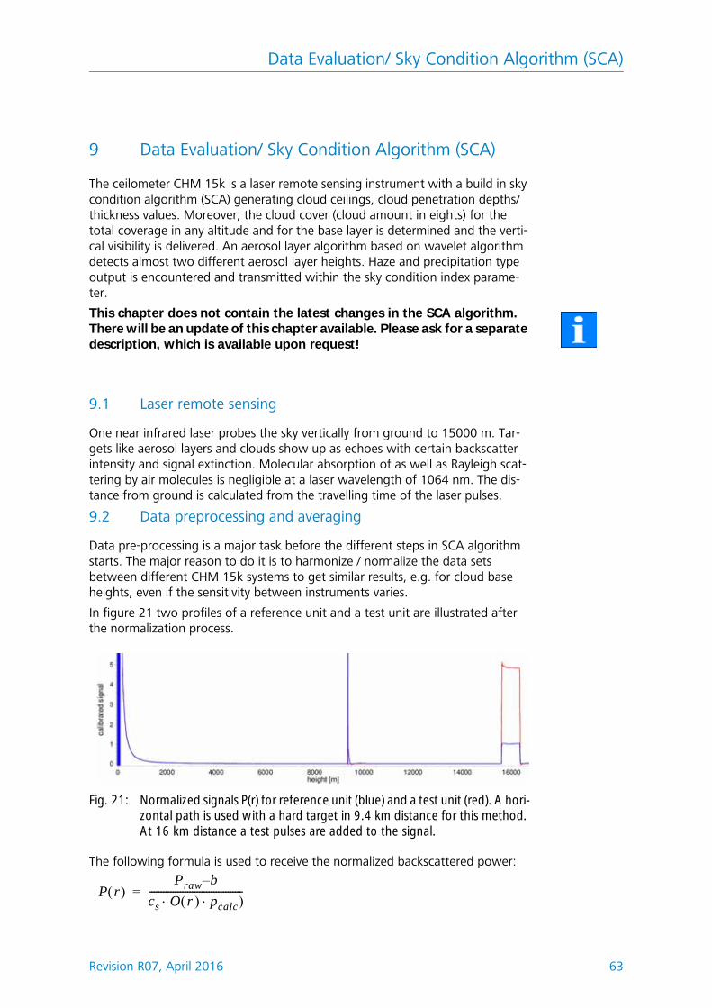
float beta_raw(time, range)units = “unitless”long_name = “normalized range cor-rected signal ((signal_raw/ lp)-b)/(c* o(r) *p_cal)*r²”
Lidar backscatter raw data with ≈15 m res-olution, normalized and range corrected.lp: laser pulses, b: baseline, c: scaling, o(r): overlap function, p_cal: calibration signal
float beta_raw_hr(time, range_hr)units = “unitless”long_name = “normalized range cor-rected signal ((signal_raw/ lp)-b)/(c* o(r) *p_cal)*r²”
Lidar backscatter with ≈5 m resolution, raw data normalized and range corrected.
int error_ext (time)long_name = “31 Bit ServiceCode” units = “unitless”
Standard status bit sequenceService codes described n chapter 8.5
short state_optics (time)long_name = “transmission of optics”units = “percent”
Optics quality index in percent
short temp_int (time)long_name = “internal temperature in K*10”units = “K”scale_factor = 10
Inner casing temperature[Kelvin x 10]
short temp_ext (time)long_name = “external temperature in K*10”units = “K”scale_factor = 10
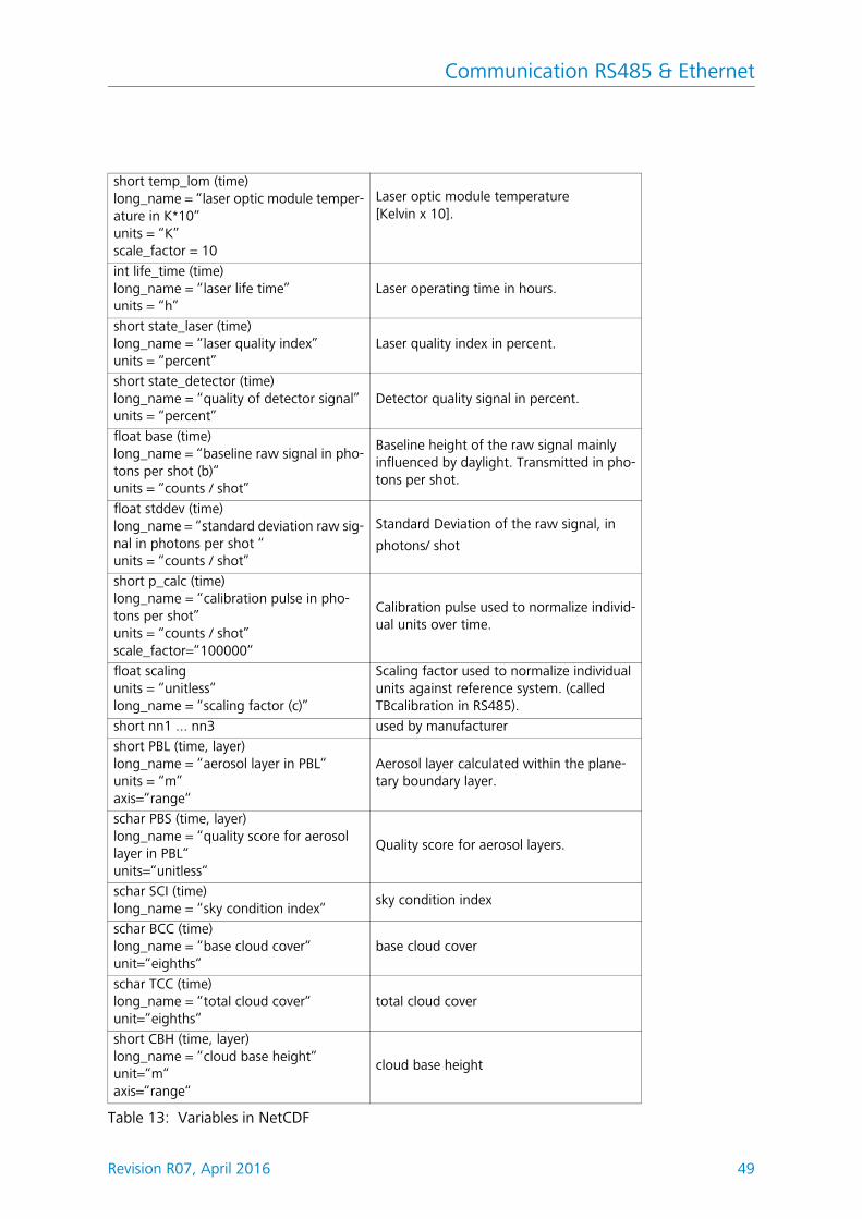
short CBH (time, layer)long_name = “cloud base height“unit=“m“axis=“range“
cloud base height
Table 13: Variables in NetCDF
Communication RS485 & Ethernet
50 Revision R07, April 2016
Global Attributes
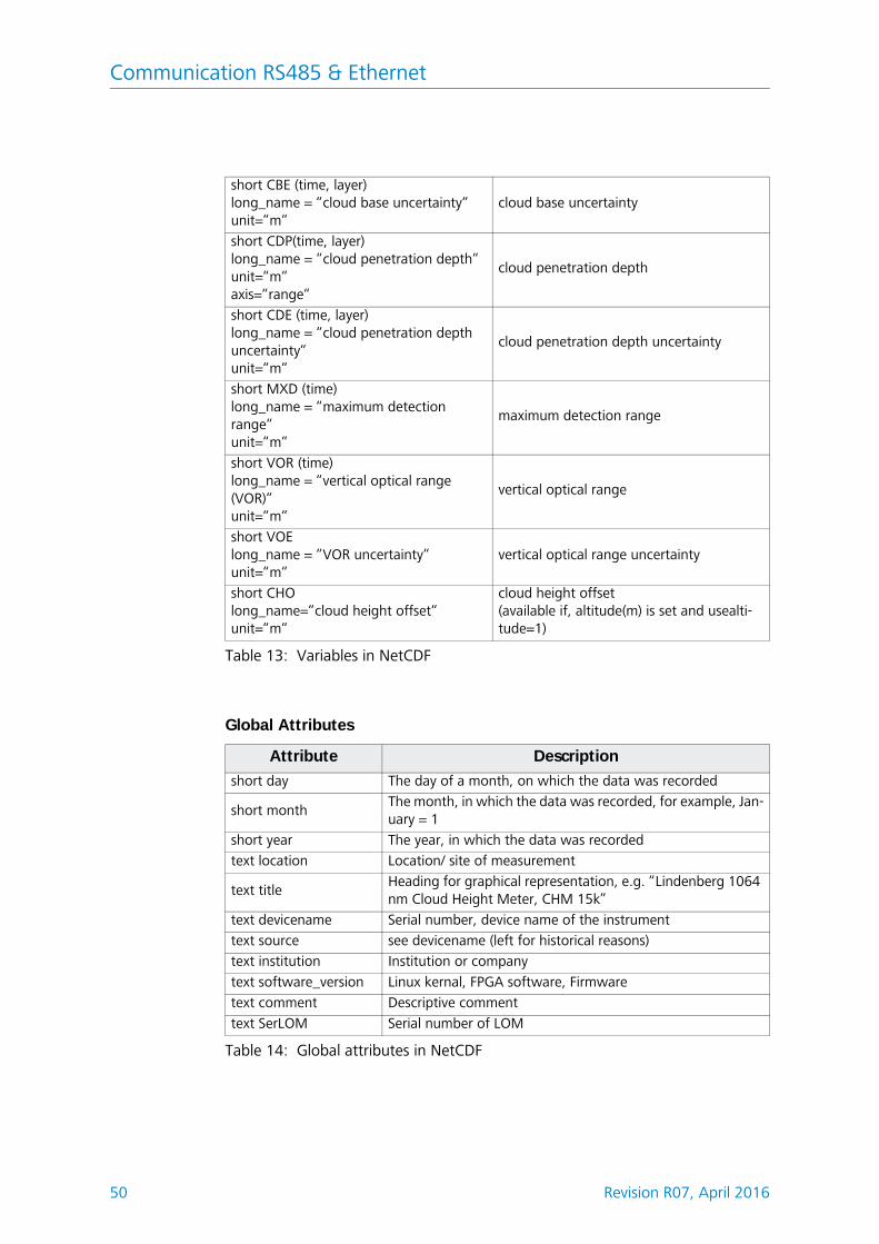
short CBE (time, layer)long_name = “cloud base uncertainty“unit=“m“
cloud base uncertainty
short CDP(time, layer)long_name = “cloud penetration depth“unit=“m“axis=“range“
cloud penetration depth
short CDE (time, layer)long_name = “cloud penetration depth uncertainty“unit=“m“
cloud penetration depth uncertainty
short MXD (time)long_name = “maximum detection range“unit=“m“
maximum detection range
short VOR (time)long_name = “vertical optical range (VOR)“unit=“m“
vertical optical range
short VOElong_name = “VOR uncertainty“unit=“m“
vertical optical range uncertainty
short CHOlong_name=“cloud height offset“unit=“m“
cloud height offset (available if, altitude(m) is set and usealti-tude=1)
Attribute Description
short day The day of a month, on which the data was recorded
short monthThe month, in which the data was recorded, for example, Jan-uary = 1
short year The year, in which the data was recorded
text location Location/ site of measurement
text titleHeading for graphical representation, e.g. “Lindenberg 1064 nm Cloud Height Meter, CHM 15k”
text devicename Serial number, device name of the instrument
text source see devicename (left for historical reasons)
text institution Institution or company
text software_version Linux kernal, FPGA software, Firmware
text comment Descriptive comment
text SerLOM Serial number of LOM
Table 14: Global attributes in NetCDF
Table 13: Variables in NetCDF
Communication RS485 & Ethernet
Revision R07, April 2016 51
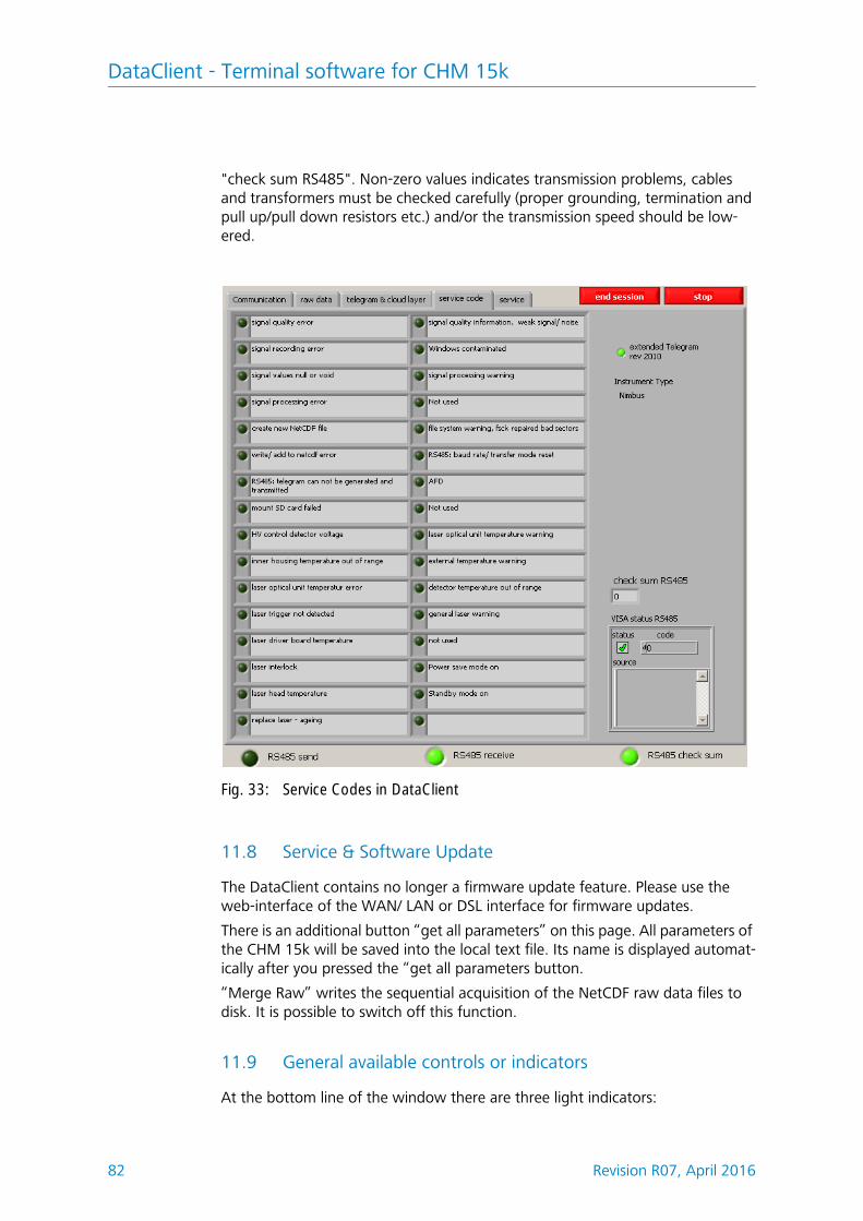
8.5 Service Codes
Table 15 explains the meaning of each bit in a 31-bit service code string. The 31-bit service code string is contained in characters 83 to 90 (91 to 99) of the stand-ard (extended) data telegram and in the raw data telegram as an eight-digit hex-adecimal number (table 8 and 11). A bit in unset state means that the corre-sponding part works properly. A bit in set state suggests an error/ warning or indicates that initialization is still underway, e. g. shortly after turning power on.
Bits are unassigned and set to “0” by default. Accordingly, a hexadecimal service code “0” indicates that the CHM 15k is fully operational.
Bit HEX code Description
0 00000001 Error: Signal quality
1 00000002 Error: Signal recording
2 00000004 Error: Signal values null or void
3 00000008 Error: Signal recording error channel 2 (not used for Nimbus)
4 00000010 Error: Create new NetCDF file
5 00000020 Error: Write / add to NetCDF
6 00000040 Error: RS485 telegram can not be generated, transmitted
7 00000080 Error: Mount SD card faile (test: write to raw buffer)
8 00000100Error: Detector high voltage control failed / cable defect or absent
9 00000200 Error: Inner housing temperature out of range
10 00000400 Error: Laser optical unit temperature error
11 00000800 Error: Laser trigger not detected
12 00001000 Warning: Laser driver board temperature
13 00002000 Error: Laser interlock
14 00004000 Error: Laser head temperature
15 00008000 Warning: Replace Laser - ageing
16 00010000 Warning: Signal quality – low signal/ noise level
17 00020000 Warning: Windows contaminated
18 00040000 Warning: Signal processing
19 00080000 Warning: Max. detection range can not be determined
20 00100000 Warning: File system, fsck repaired bad sectors
21 00200000 Warning: RS485 baud rate/ transfer mode reset
22 00400000 Warning: AFD
23 00800000 Warning: configuration problem
24 01000000 Warning: Laser optical unit temperature
25 02000000 Warning: External temperature
26 04000000 Warning: Detector temperature out of range
27 08000000 Warning: General laser issue
28 10000000 Note: NOL > 3 and standard telegram selected
29 20000000 Note: Power save mode on
30 40000000 Note: Standby mode on
Table 15: Service codes/ status bits
Communication RS485 & Ethernet
52 Revision R07, April 2016
8.6 Firmware Update
The CHM 15k Nimbus system can be updated via Ethernet interface (WAN/ LAN connection). Please check the web browser section below for details. A supe-ruser password is needed to perform such an update.The original update service via the RS485 interface is no longer available.
Communication RS485 & Ethernet
Revision R07, April 2016 53
8.7 Communication via Ethernet - Web-Interface
The communication with the CHM 15k Nimbus using the Ethernet connection is a fast, secure and system independent way. Inside the instrument runs an Apache web server. It enables a communication and configuration platform via web interface to handle firmware updates, quick views of measuring results or downloading full day NetCDF raw data files.
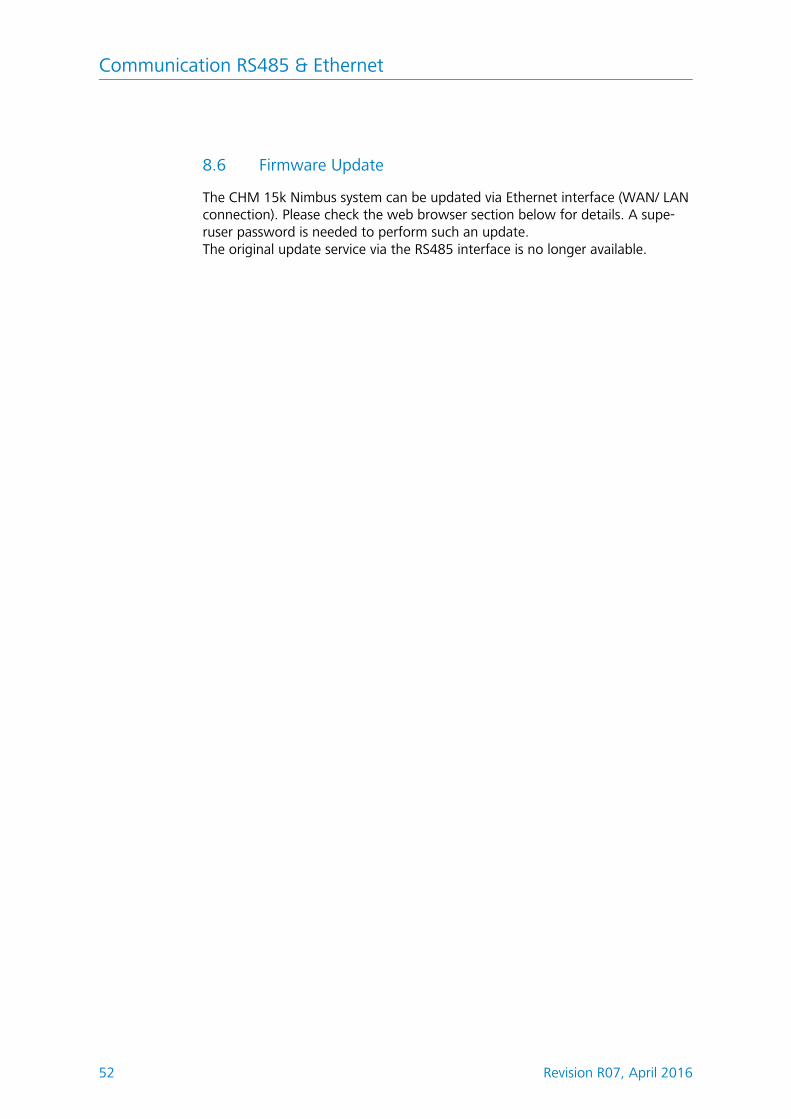
Figure 12 shows the start screen after a successful connection to the instrument (start-up procedure in section 7.2).
In general the web interface does include the following right management:l End-user can check the state of the instrument.l Super user can additionally download NetCDF files, configure the instru-
ment, download user manual and further configuration files.l Service user can update the firmware, set the instrument serial number,
download the service manual and upload configuration files.By entering a password in the “Administration” form field, downloadable and configurable elements are enabled, e.g. the IP network configuration (Fig. 15).
The status info on device panel and the process warning panel are displaying warnings and errors updated once a minute. Listed codes in the status info are corresponding to service codes in table 15. The process warning panel (figure 20) contains more details for service people. In super user or service mode the device panel contains buttons to switch off or restart the system.
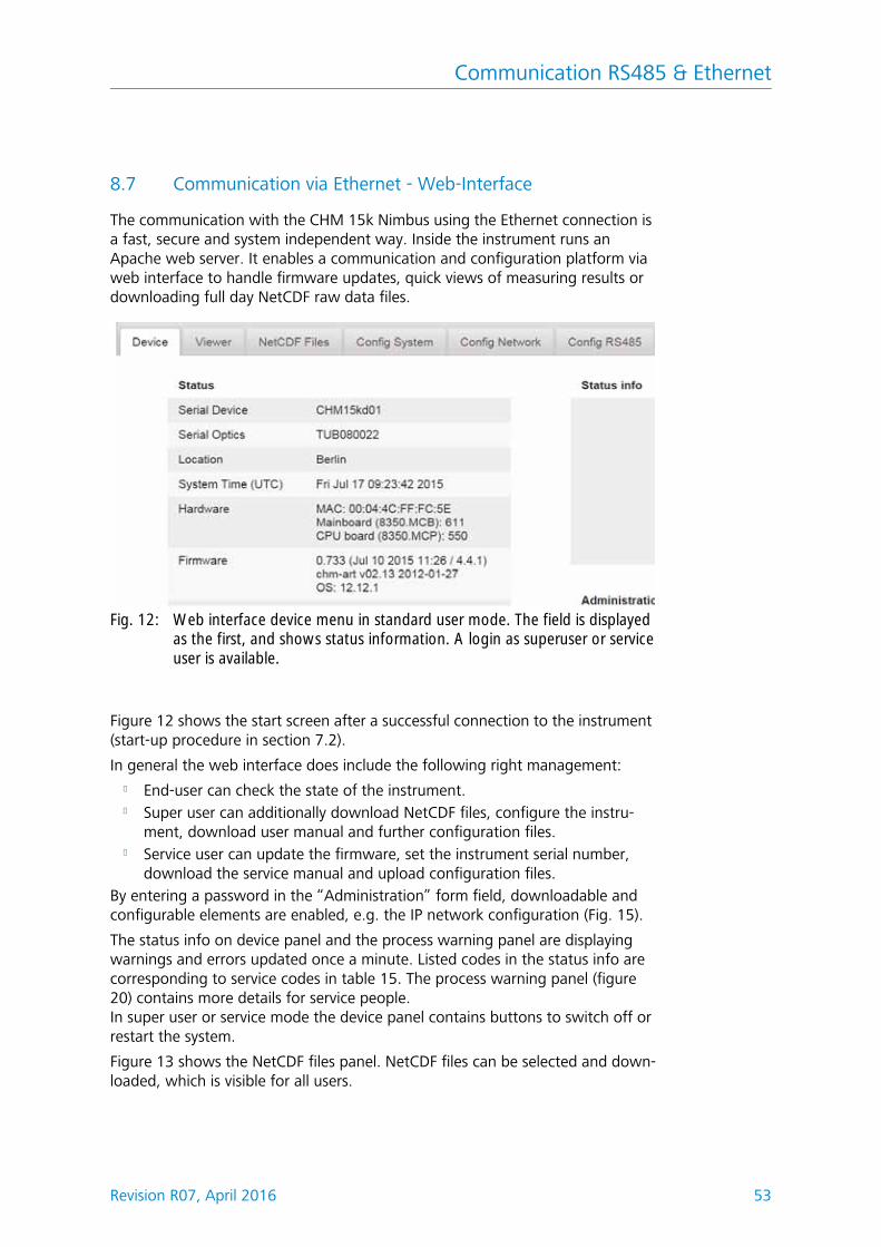
Figure 13 shows the NetCDF files panel. NetCDF files can be selected and down-loaded, which is visible for all users.
Fig. 12: Web interface device menu in standard user mode. The field is displayedas the first, and shows status information. A login as superuser or serviceuser is available.
Communication RS485 & Ethernet
54 Revision R07, April 2016
Fig. 13: Web interface NetCDF files (superuser): Displays a list of NetCDF filesstored on the internal SD Card. NetCDF files can be downloaded by double–clicking in superuser or service mode.
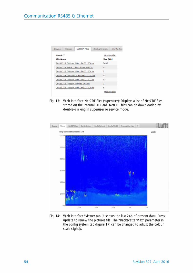
Fig. 14: Web interface/ viewer tab: It shows the last 24h of present data. Pressupdate to renew the pictures file. The “BackscatterMax” parameter in the config system tab (figure 17) can be changed to adjust the colour scale slightly.
Communication RS485 & Ethernet
Revision R07, April 2016 55
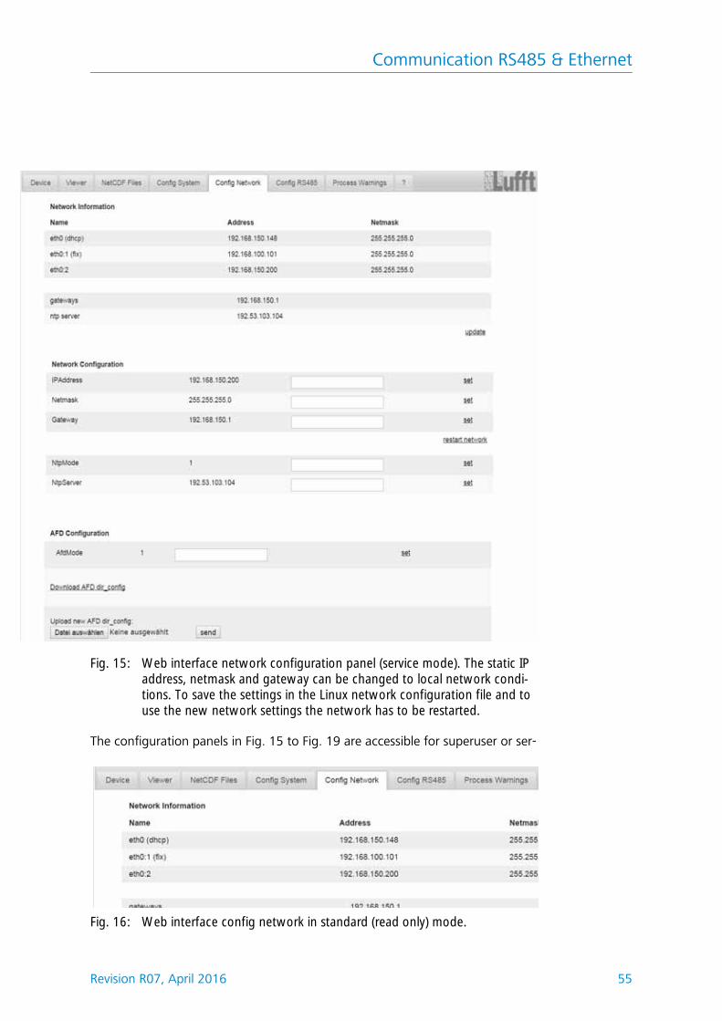
The configuration panels in Fig. 15 to Fig. 19 are accessible for superuser or ser-
Fig. 15: Web interface network configuration panel (service mode). The static IP address, netmask and gateway can be changed to local network condi-tions. To save the settings in the Linux network configuration file and to use the new network settings the network has to be restarted.
Fig. 16: Web interface config network in standard (read only) mode.
Communication RS485 & Ethernet
56 Revision R07, April 2016
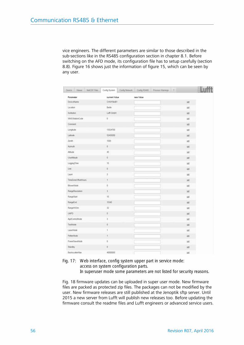
vice engineers. The different parameters are similar to those described in the sub-sections like in the RS485 configuration section in chapter 8.1. Before switching on the AFD mode, its configuration file has to setup carefully (section 8.8). Figure 16 shows just the information of figure 15, which can be seen by any user.
Fig. 18 firmware updates can be uploaded in super user mode. New firmware files are packed as protected zip files. The packages can not be modified by the user. New firmware releases are still published at the Jenoptik sftp server. Until 2015 a new server from Lufft will publish new releases too. Before updating the firmware consult the readme files and Lufft engineers or advanced service users.
Fig. 17: Web interface, config system upper part in service mode: access on system configuration parts. In superuser mode some parameters are not listed for security reasons.
Communication RS485 & Ethernet
Revision R07, April 2016 57
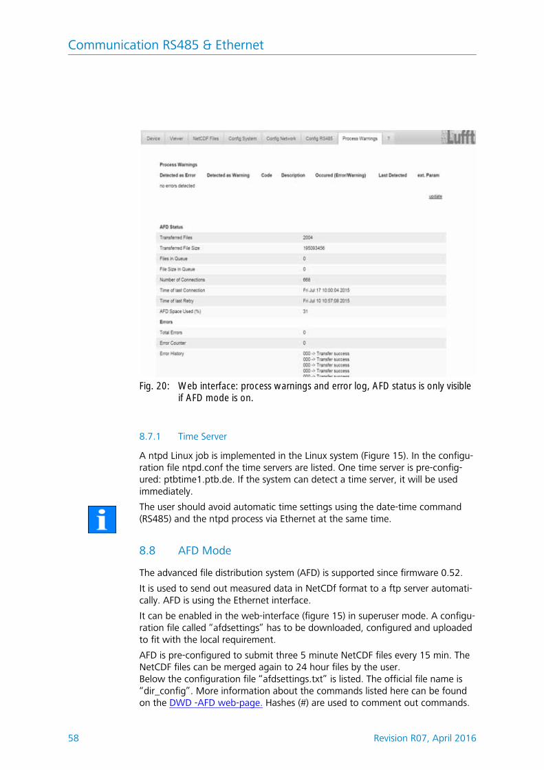
The upper section of process warning tab in figure 20 is mainly used by the Lufft service to identify firmware problems and special errors. The lower section shows information about the advanced file distribution (AFD) mode. If AFD mode is switched on the status of transferred files is shown. The properly setup or any mistakes have been done in the configuration with the AFD configuration file can be identified.
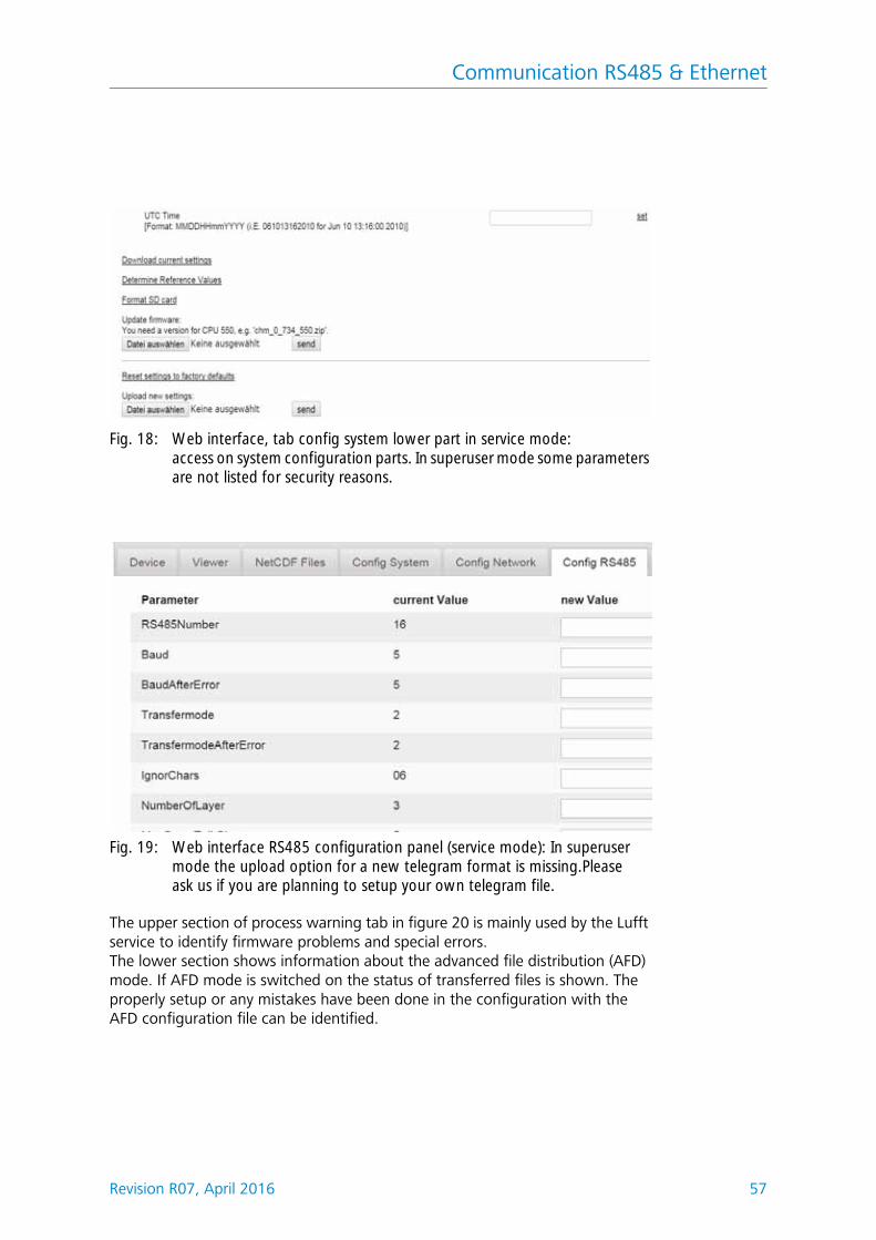
Fig. 18: Web interface, tab config system lower part in service mode: access on system configuration parts. In superuser mode some parameters are not listed for security reasons.
Fig. 19: Web interface RS485 configuration panel (service mode): In superusermode the upload option for a new telegram format is missing.Please ask us if you are planning to setup your own telegram file.
Communication RS485 & Ethernet
58 Revision R07, April 2016
8.7.1 Time Server
A ntpd Linux job is implemented in the Linux system (Figure 15). In the configu-ration file ntpd.conf the time servers are listed. One time server is pre-config-ured: ptbtime1.ptb.de. If the system can detect a time server, it will be used immediately.
The user should avoid automatic time settings using the date-time command (RS485) and the ntpd process via Ethernet at the same time.
8.8 AFD Mode
The advanced file distribution system (AFD) is supported since firmware 0.52.
It is used to send out measured data in NetCDf format to a ftp server automati-cally. AFD is using the Ethernet interface.
It can be enabled in the web-interface (figure 15) in superuser mode. A configu-ration file called “afdsettings” has to be downloaded, configured and uploaded to fit with the local requirement.
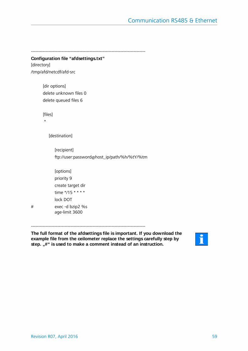
AFD is pre-configured to submit three 5 minute NetCDF files every 15 min. The NetCDF files can be merged again to 24 hour files by the user.Below the configuration file “afdsettings.txt” is listed. The official file name is “dir_config”. More information about the commands listed here can be found on the DWD -AFD web-page. Hashes (#) are used to comment out commands.
Fig. 20: Web interface: process warnings and error log, AFD status is only visible if AFD mode is on.
The full format of the afdsettings file is important. If you download the example file from the ceilometer replace the settings carefully step by step. „#“ is used to make a comment instead of an instruction.
Communication RS485 & Ethernet
60 Revision R07, April 2016
Example for the file “afdsetting.txt”Ftp server 192.168.1.51
Every 15 minute bzip compressed files are transferred to a directory specified by subdirectory/hostname/year/month. Hostname “%h” is the instrument name like CHM060001, year “%tY” and month “%tm” are specified by the instrument time settings.
A double slash // after the IP address indicates that the path starts from root directory, a single slash / that it starts from the ftp home directory.
A ftp path in a windows directory may look like this:
The file will be stored in the home directory of the ftp server in the sub path /%h/%tY/%tm.
The command „time * * * * *“ sends out the 5 min NetCDF file immediately when it is generated.
Communication RS485 & Ethernet
Revision R07, April 2016 61
8.9 Telegram over Ethernet
The software implementation over the Ethernet interface provides also a method to receive data telegrams. The raw data telegram described in 8.3.5 can be polled.
On Windows operating systems the Nmap/ Ncat binaries can be downloaded and installed form the server http://nmap.org/ncat/, The web-page provides also various binaries and source codes for other operating systems.
After installation and setup the data telegram can be accessed by entering the polling command:
ncat <IP-address> <Port>
For example:
ncat 192.168.100.101 11000
or the old release from ncat: netcat 192.168.100.101 11000
The port number is up to firmware release 0.726 8000, after that (December 2014) it has been changed to port number11000.
The raw data telegram is still uuencoded like in the RS485 transfer mode and must uudecoded before it can be read.
The ceilometer CHM 15k is a laser remote sensing instrument with a build in sky condition algorithm (SCA) generating cloud ceilings, cloud penetration depths/ thickness values. Moreover, the cloud cover (cloud amount in eights) for the total coverage in any altitude and for the base layer is determined and the verti-cal visibility is delivered. An aerosol layer algorithm based on wavelet algorithm detects almost two different aerosol layer heights. Haze and precipitation type output is encountered and transmitted within the sky condition index parame-ter.
This chapter does not contain the latest changes in the SCA algorithm. There will be an update of this chapter available. Please ask for a separate description, which is available upon request!
9.1 Laser remote sensing
One near infrared laser probes the sky vertically from ground to 15000 m. Tar-gets like aerosol layers and clouds show up as echoes with certain backscatter intensity and signal extinction. Molecular absorption of as well as Rayleigh scat-tering by air molecules is negligible at a laser wavelength of 1064 nm. The dis-tance from ground is calculated from the travelling time of the laser pulses.
9.2 Data preprocessing and averaging
Data pre-processing is a major task before the different steps in SCA algorithm starts. The major reason to do it is to harmonize / normalize the data sets between different CHM 15k systems to get similar results, e.g. for cloud base heights, even if the sensitivity between instruments varies.
In figure 21 two profiles of a reference unit and a test unit are illustrated after the normalization process.
The following formula is used to receive the normalized backscattered power:
Fig. 21: Normalized signals P(r) for reference unit (blue) and a test unit (red). A hori-zontal path is used with a hard target in 9.4 km distance for this method. At 16 km distance a test pulses are added to the signal.
P r Praw b–
cs O r pcalc ---------------------------------------=
Data Evaluation/ Sky Condition Algorithm (SCA)
64 Revision R07, April 2016
with, Praw as raw backscatter profile (photon counts), b. baseline, p_calc : aver-age test pulse intensity, O(r) overlap function, cs: calibration constant and Pc(r) is the normalized backscatter signal.
In another step, normalized data are calibrated to get attenuated backscatter values beta_raw, which are stored in the NetCDF files. For cloud processing, and aerosol layer determination another pre-processing step will taken into account, which is shown in figure 22. It shows an example of the time average used to determine clouds in different altitudes from the range corrected backscatter sig-nal. The values, where the time average starts to where it stops, here in the fig-ure 3000m, 6000m) depends on the focus of usage of the ceilometer.
9.3 Cloud ceilings/ cloud base heights
After successful pre-processing the averaged backscatter profile is used to iden-tify cloud echoes, rain, fog, aerosol layers and discriminate these events from each other.
Figure 23 show a daily color coded intensity plot, where all layers with a signifi-cant backscatter value marked black. The algorithm identifies rain and aerosol in these structures and calculates in a next step cloud bases and penetration depths.
Fig. 22: Example for a time average used to calculate cloud bases in different altitudes.
Fig. 23: Cloud detection algorithm.
Data Evaluation/ Sky Condition Algorithm (SCA)
Revision R07, April 2016 65
9.4 Cloud Penetration Depth
A cloud penetration depth is established by identifying a cloud lower and upper level using the threshold level" ThAlphaStart(m-1E7)" (9.2). The subtraction of these values result in the cloud penetration depth. The "ThAlphaFactor(%)" is used to check the surrounding area of the calculated values. Both values com-bined deliver the standard deviation for the penetration depth of a cloud layer. Figure 24 show how the evaluation process for the cloud parameters are done.
9.5 Determination of Maximum Detection Range
The maximum detection range corresponds to the maximum distance at which significant signals can still be measured. It follows from averaged signal/noise ratios versus the distance range. At heights which are beyond the planetary boundary layer, significant signals are only generated by clouds. In presents of clouds the maximum detection range determined by means of the penetration depth of the highest detectable cloud layer.
Data Evaluation/ Sky Condition Algorithm (SCA)
66 Revision R07, April 2016
9.6 Vertical optical range
The method for calculating VOR (vertical optical range) is described in the stand-ard ISO 28902-1:2012. First an extinction profile a is calculated from the backs-catter signal. The VOR is where the integral of extinctions equals 3.
9.7 Precipitation and haze
Haze and precipitation types are detected by multiple scattering. Usually only single scattering is considered as a signal source. Strong atmospheric turbidity and high particle density respectively produce a stronger signal than usual close to the instrument. An integral over the signal in certain ranges is used to evalu-ate haze and precipitation.
9.8 Mixed layer height
Pollution from sources at ground level is spreading to a height depending on atmospheric conditions. The resulting aerosol layer are identified using a typical signature in the backscatter signal. The mixed layer height can be determined by finding the lowest aerosol layer height. The quality of the identified aerosol layers are strongly dependend on local con-ditions and time. Table 16 shows an index describing the quality of the identified aerosol layers with respect to high accuracy and low uncertainty..
Q-Index description
/ (telegram)
-1 (NetCDF)
not enough raw data for calculation
- (telegram)
-2 /NetCDF)
system hardware failure or system not ready
/ (telegram)
-3 (NetCDF)
algorithm can’t generate value
0 no layer detected,
(index was not calculated in older firmware releases)1 layer can be detected, but with a high uncertainty and low
accuracy9 layer can be detected with a high accuracy (less than 50 m)
Table 16: Quality Index description, of the aerosol layer height
30
VOR
drr
Data Evaluation/ Sky Condition Algorithm (SCA)
Revision R07, April 2016 67
9.9 Parameters for data evaluation
A set of parameters controls the data evaluation routine. The system dependend values are stored on the laser optical unit. They are listed within the table 3 and table 4.
9.10 Cloud amount/ cloud cover (BCC / TCC)
The cloud amount value will be determined from calculated cloud bases, where their temporal history the will be treated. The base cloud cover (BCC) from the lowest cloud base and the total cloud cover (TCC) are written in NetCDF files.
The considered time intervall depends on the altitude, see Figure 25. For each altitude intervall the frequency of cloud bases are calculated. This histogram will be smoothed using a height depending weight function. Within the smoothed frequency distribution, peaks will be separated. All cloud bases in the space of a peak will be clustered to one cloud layer.
The calculation of the total cloud cover value and the separated cloud layers are done within a rectangle depending on time and altitude. For this purpose the selected time intervall (truncated cone) will be divided in a fixed number of small truncated cones. Parts containing cloud bases are counted against the total number of cone parts. The cloud cover values is expressed as a percentage value from these comparison. Finally the percentage value is exppressed in oktas.Table 17 lists the WMO code for the cloud cover index. The please check the
sdsdsdsdsd
s
Fig. 24: Evaluation of cloud parameters, for the altitude of cloud bases and penetration depth the range vector will be corrected by the zenith angle
Threshold + 20% Threshold Threshold – 20%
Distance
Inte
nsit
y
Cloud height
Penetration depth
Cloud height std. deviation
Data Evaluation/ Sky Condition Algorithm (SCA)
68 Revision R07, April 2016
firmware release if the code is fully supported.
9.11 Sky condition index (SCI)
The sky condition index is written in the extended data telegram and is a stand-ard variable of the NetCDF file. It should allow the user to better interpret data, e.g. when clouds are not detected. In older CHM 15k system the variable was handled as precipitation index. It is used in the following way:
,
oktas description
- (telegram)
-2 (NetCDF)
system hardware failure or system not ready
/ (telegram)
-1 (NetCDF)
-3 (NetCDF)
cloud is indiscernible for reasons other than fog or other meteorological phenomena, or observation is not made
0 clear sky1 1 okta : 1/10 - 2/102 2 oktas : 2/10 - 3/103 3 oktas : 4/10 4 4 oktas : 5/105 5 oktas : 6/10 6 6 oktas : 7/10 - 8/107 7 oktas or more, but not 8 oktas : 9/10 or more, but not 10/108 8 oktas : 10/109 9 - sky obscured by fog or other meteorological phenomena
Table 17: Cloud amount / cloud cover values related to WMO code 2700.
Value Description
-- (telegram)
-2 (NetCDF)
system hardware failure or system not ready
00 no fog nor precipitation detected01 rain02 fog, no clouds detectable03 snow or freezing rain04 window transmission reduced, droplets on the window// (telegram)
-1 (NetCDF)
-3 (NetCDF)
observation is not made,in NetCDF, the numerical values -1, -3 are used instead of // in the telegram
Table 18: Sky condition index (SCI)
Data Evaluation/ Sky Condition Algorithm (SCA)
Revision R07, April 2016 69
Fig. 25: Cloud amount algorithm: The selected time interval used for the cloud cover calculation depends on the range, a truncated cone function is used for the calculation.
Cleaning, Maintenance & Service Instructions
Revision R07, April 2016 71
10 Cleaning, Maintenance & Service Instructions
DANGERLaser radiation! There is danger of eye injury!Class 1M laser radiation, if viewed over an extended period of time, may cause damage to the eyes such as glare or irritation or even full loss of eyesight. Do not directly look into the laser beam. Under no circum-stances should the laser beam be directly inspected with the help of opti-cal instruments (e.g. field glasses). Make also sure that no items with a reflecting surface (e.g. watches) are placed in the beam path.
10.1 Cleaning
1 for average dust load level of 25 -35 μg/m³ in the air
2 as soon as snow reaches the air inlet plane of the fans
Interval Cleaning Comment/Aids
Quaterly1 Clean glass panels (Fig. 26) mainly with a lot water and some mild soap.Use your hands to dispense some soap at the windows, clean again with water, use distilled water for the finish.
Dishwashing liquid, water, hands,
As required Remove sedimentation from space below casing top
Neutral cleaning agents, micro-fibre wipes
As required Remove potential plant pockets in front of fan inlet grids (rear side)
Keep fan intake area unob-structed, see Fig. 27
As required Remove snow2 Keep fan intake area unob-structed, see Fig. 27
Table 19: Cleaning schedule and cleaning action
Cleaning, Maintenance & Service Instructions
72 Revision R07, April 2016
Fig. 26: Glass panels have to be cleaned
1 Laser outlet on left side
2 Casing top
3 Glass panels; windows shall be cleaned without micro-fibre wipes
NOTEThe CHM 15k Cloud Height Meter requires regular maintenance. Mainte-nance work may not be performed by anyone other than service person-nel of G. Lufft GmbH or specially trained customer technicians. For detailed instructions on maintenance, you should consult the Service Manual.
Cleaning, Maintenance & Service Instructions
Revision R07, April 2016 73
10.2 Maintenance Intervals & Action
CAUTIONDanger of physical injury by electric current! Use miniature circuit breaker to cut power supply before any kind of maintenance or repair work at the Cloud Height Meter.
10.2.1 Replacement of Air Dehumidifier Bag [67]
l Open outer and inner door l Remove air dehumidifier bag (item 2 of Fig. 18)l Glue new air dehumidifier bag to inner door l Close inner and outer door
10.2.2 Replacement of Rubber Seal [34] at Inner Door
l Open outer and inner door l Detach cable [69] of thermostat at clip terminal XK013l Remove rubber seal from inner door (item 1 of Fig. 18) l Mount new rubber seal to inner door (using suspension points)l Close inner and outer door
check of intactness of air dehumidifier bag CONTAINER DRI II"
at least once a year
Replace air dehumidifier bag CONTAINER DRI II"
Three- to four-yearly
Replace laser optic module if signs of laser wear - falling repetition rate;replace SD-card
only service personal
Five-yearly Replace inner door rubber seal (material fatigue)
only service personal
Five-yearly Replace lightning ductor following lightning strike
only service personal
Eight-yearly Replace electronic mainboard only service personal
Table 20: Preventive maintenance intervals and action
Cleaning, Maintenance & Service Instructions
74 Revision R07, April 2016
Fig. 28: Air dehumidifier bag (2) and rubber seal (1).
If you have questions or if a procedure mentioned in the User Manual fails to fix a particular problem, you are advised to contact your on-site service technician or G. Lufft GmbH.
NOTEFor other detailed information, which is in excess of this User Manual (maintenance, replacement and system assembly particulars), you should refer to the Service Manual. The Service Manual is only available to Lufft personnel or specially trained technicians who have a documented proof of qualification (valid certificate) to handle respective maintenance and service work responsibilities.
DataClient - Terminal software for CHM 15k
Revision R07, April 2016 75
11 DataClient - Terminal software for CHM 15k
The main purpose of the Terminal program DataClient is receiving data tele-grams from CHM 15k instruments and storing these data on local disks. Moreo-ver, it can also be used for remote maintenance and diagnosis of connected CHM 15k instruments. Basic commands are included for reading CHM 15k parameters, and with some restrictions also writing these parameters. Com-mands are described in chapter 8 of this manual.
11.1 Software Installation
DataClient requires a Windows 7, Vista, XP or (2000) operating system to install the software and its runtime engine. Precondition is that instrument communica-tion could be established via the RS485 connection line to the CHM 15k, which is typically done by a RS232-RS485 or USB-RS485 interface adapter.
The DataClient software is included in each CHM system delivered from Lufft. The standard CD includes:
l full installation: setup file for the program and the runtime enginel single program files, which can be used for updates if the runtime was
already installed.l manual of the CHM 15k instrumentl additional information/ tools
In addition, another product CD exists, which includes a visualization program of raw data.
While the standard installation process is running, the installation directory can be changed from its default values.
Default: c:\Lufft\Programs
Additional directories used by the program are:l c:\Lufft\Measure (data base path)l c:\Lufft\Image (used by the old software JO-Visual only to save images)l local temporary file path to save raw data.
The user needs read and write access to the Lufft program and data folder and the “temp” folder. Because the measure and image paths are not fixed, be sure that the configuration file JO-Visual.ini for the old visualisation program and the path variables for the DataClient program have been changed in the same way. Starting from August 2014 the new visualization program CHMViewer has replaced the JO-Visual software.
11.2 Convention for the file names
DataClient generates ASCII files with a file name and path convention depending on the telegram (see chapter 8.3.3, 8.3.4, 8.3.4) and the “filestructure” start parameter.
DataClient - Terminal software for CHM 15k
76 Revision R07, April 2016
Please notice that the standard telegram does not contain the information of the instrument name of the instrument. Without additional queries the name is set to “CHMstndrd”. The instrument name can be set by querying for the device-name (old fabname) or for all parameter in the start sequence form field or within the autostart process.
11.3 Start dialog
For the DataClient a start dialogue exists to configure the instrument (section 11.3). Furthermore an autostart mode exists to avoid the pop up of the start dia-logue. The command line parameters and the pre-installed autostart.cmd exam-ple file are explained in section 11.10.Immediately afters start the following dialog window appears.
The four input fields on the left side should be filled with appropriate values. If the current baud rate of the connected CHM 15k is unknown, then use the value “9600, which is the default baud rate. A higher baud rate, eg. 38400, is recom-mended for raw data transfer and could be changed later on, see top figure 30.
If you poll the CHM 15k many times with an incorrect baud rate the CHM 15k will automatically set its baud rate to the “BaudrateAfterError” value, which is also predefined to 9600 Baud, after one logging interval.
To go on:
– With “Cancel” the program terminates.– With “Continue” the program will enter normal operation mode with five
pages, which are explained in the following sections.
11.4 Communication tab
Fig. 30: Main page “Communication”, where all actions are carried out. The remaining four pages serve the monitoring of the measuring data as well as service information.
All control elements are placed on the left side of the page. Responses of the
DataClient - Terminal software for CHM 15k
78 Revision R07, April 2016
CHM 15k can be read unfiltered in the display box „CHM 15k answer“. The raw data part of raw data telegrams is not displayed here. In addition, they are shown in the service tab field.
Details of control elements. The top row encloses the interface parameters:
– RS485 port: Here the RS232 port which is connected to the RS232-485 adaptor is displayed. It can only be changed by the initial dialogue (see above).
– RS485 number: The RS485 ID-number of the connected CHM 15k device. The value “16” should only be exchanged if necessary.
– baud: With this electoral switch the baud rates 1200, 2400, 4800, 9600, 19600 or 38400 bauds can be selected. Note, that the factory default value is 9600 baud.
Below there is a button named “auto transfer off”. Pressing this button means, that all previous automatic transfer modes will be cancelled.
The next block contains three buttons for single telegram acquisitions:
– small: The standard data telegram is requested, see user guide, chapter 8.3.3
– large: The advanced data telegram is requested, see user guide, chapter 8.3.4
– all: The raw data telegram is requested, see user guide, chapter 8.3.5
The next block contains three buttons for automatic polling of data telegrams.
Below there is an input field for the internal measure period (in seconds) of the CHM 15k. The associated button must be pressed, if this value should go into effect for the CHM 15k device. Nevertheless, this value is also used as the time between automatic polling mode acquisitions described in the previous para-graph, and changes of the value in this sense are applied without pressing the button “set measure period”!
The next block contains three buttons for automatic telegram output, initiated by the CHM 15k itself, i.e., not by polling.
Remark: All six automatic telegram modes will be cancelled by pressing the but-ton “auto transfer off”, or also by acquisition of one of the three single tele-grams.
Now a block follows for reading and writing internal CHM 15k parameters:
– device variable: Here the name of the concerning CHM 15 parameter has to be specified. A summary of these parameters can be find in the user guide, tables 4 and 16.
– set value: Value for the “send set command”.– send get command: The current value of the parameter is displayed in
the box “CHM 15k answer” on the right side.– send set command: Value "set value" is transmitted to the CHM 15k. Pro-
vided that the suitable parameter is really alterable and is in the permissi-
DataClient - Terminal software for CHM 15k
Revision R07, April 2016 79
ble range, the successful parameter update will be acknowledged in the box “CHM 15k answer”. If one of these restrictions is violated, there is no acknowledgement and the parameter is not changed. For safety reasons some of the parameters are alterable only in the service mode, see user guide, section 8.6.
– switch “auto clean of input fields”: If activated, the two input fields “device variable” and “set value” will be erased after each set or get command
Finally another two paths are adjustable which concern local paths of the com-puter, where the DataClient runs:
– measure path: In this directory the telegram messages of CHM 15k will be saved in subdirectory structure, which depends on device name and date, for later evaluations.
– program update path: If a software update has to be carried out (see last page) this path must contain the new program files to be transmitted. This path is to be set here only in the case, if during a running update process DataClient is terminated and is newly started later again. In the latter case the update directory has to be customized immediately after the restart.
11.5 Raw Data
DataClient - Terminal software for CHM 15k
80 Revision R07, April 2016
Fig. 31: Raw data tab. In the graph shown here the data of the lasttransmitted raw data telegrams are captured.
In fact, a simple moving average (SMA) filter is applied on the last 10 raw data telegrams, this number 10 is changeable in the input field “maximum number of data for SMA”. If the value 1 is set in this field, the raw data of the last received raw data telegram are displayed in the graph. The field “actual number of data used for SMA” contains the number of raw data records used for SMA calcula-tion - without change of parameter “maximum number of data for SMA” this value should grow with succeeding telegrams up to 10.
“NetCDF filename” specifies the entire local path of the last transmitted raw data telegram, this file is overwritten every time a raw data telegram is received.
11.6 Telegram & Cloud Layer
DataClient - Terminal software for CHM 15k
Revision R07, April 2016 81
Fig. 32: All types of telegrams contain cloud layer and associated penetration depths; in the advanced and raw data telegrams also the standard devia-tions of these values and aerosol layers are transmitted. These values are displayed on the left side. The right side shows the course of cloud heights over the last 120 (tbd) telegrams.
In the above example we don’t see recognized cloud layer, hence the field for cloud layer is marked with NODET or NODT, short form for "not detected". The vertical visibility is also not detectable and the detection range is very high. Two aesorol layers are identified. In sum we can assume clear sky condition.
11.7 Service Code
Each telegram message contains a service code field of 32 bit. The service code tab lists clearly the Bits by their meaning, see also chapter 8.5 for service code details. A signal light indicates an alert of the suitable function.
During the start phase of CHM 15k some of these signals may light up. How-ever, after some minutes the CHM 15k should enter normal operation mode with all lights switched off. Lights are hints for trouble-shooting.
Every received message from CHM 15k (telegrams & set/get command answers) contains a checksum in terms of two’s complement. Transmission is checked by this gibberish total, proper transmission is indicated by value zero in the field
DataClient - Terminal software for CHM 15k
82 Revision R07, April 2016
"check sum RS485". Non-zero values indicates transmission problems, cables and transformers must be checked carefully (proper grounding, termination and pull up/pull down resistors etc.) and/or the transmission speed should be low-ered.
11.8 Service & Software Update
The DataClient contains no longer a firmware update feature. Please use the web-interface of the WAN/ LAN or DSL interface for firmware updates.
There is an additional button “get all parameters” on this page. All parameters of the CHM 15k will be saved into the local text file. Its name is displayed automat-ically after you pressed the “get all parameters button.
“Merge Raw” writes the sequential acquisition of the NetCDF raw data files to disk. It is possible to switch off this function.
11.9 General available controls or indicators
At the bottom line of the window there are three light indicators:
Fig. 33: Service Codes in DataClient
DataClient - Terminal software for CHM 15k
Revision R07, April 2016 83
– RS485 send: Normally this light should only blink for a short moment, while sending commands. An exception is a running software update, where large blocks of data will be sent to the CHM 15k, in this case this light shines for some seconds.
– RS485 receive: This light shines while receiving data from CHM 15k. Dur-ing this period send actions (like set/get variables) must not be done because there is only a half-duplex RS485 connection to the CHM 15k, so simultaneous sending and receiving is not possible.
– RS485 check sum: Each answer of CHM 15k (telegram or set/get com-mand confirmation) is closed by two checksum bytes (complement of two). The result of check is indicated by this light: green - ok / red - fail-ure.
There are two buttons in the upper right corner of the program window:
“end session”: The current session is finished, and the very first start dialog (with RS 485 connection parameters) appears again. Now possibly changed connec-tion values should be filled in and another session can start.
“stop”: The program terminates.
11.10 Autostart and command line parameters
The file “Autostart_DataClient.cmd” allows an automatic startup procedure of the DataClient software. The default path variables listed below are used to have a seperate path for the measuring software, the data and configuration files, which is not restricted by the Windows operating system. The standard file includes all command line options, which can be changed due to user require-ments:
It is important that the current internal baud rate of the CHM 15k (set in previ-ous sessions) must coincide with the baud rate in this command line, in this example value 3 means 9600 baud. Otherwise connection failures will occur, see chapter 11.3 (start dialog). In this example the CHM PC clock is synchronized every 6 hours.
DataClient can be invoked with one or more of the following command line parameters:
l –baud <index>:
DataClient - Terminal software for CHM 15k
84 Revision R07, April 2016
Possible values of <index> can be 0 (1200 baud), 1 (2400 baud), 2 (4800 baud) , 3 (9600 baud, default) , 4 (19200 baud) , 5 (38400 baud) , 6 (57600 baud) or 7 (115200 baud).
l –com <port>:Usually <port> is one of the serial ports ASRL1::INSTR (default), ASRL2::INSTR, and so on. Depending on the Labview environment on the host PC, the alternative names COM1, COM2 may be available too.
l –device <number>:The default value is 16, suitable for the factory default RS485 number of a CHM15k.
l –measurepath <path>:<path> specifies the main directory of locally saved raw data telegrams (NetCDF). Default <path> is D:\Measure
l –ncpath <filename>:<filename> specifies the full qualified filename (i.e. including path) of a required temporary NetCDF file for the decoding of raw data telegrams. Therefore the user must have read and write access to this path. Default <filename> is C:\WHM\uudecode.nc
l –utcupdaterate <hours>:Any positive value means that the internal CHM PC clock is synchronized with the client PC clock (converted to UTC) every <hour> hours. Default value for <hour> is 0, i.e., no synchronization is done.
l –startseq <number>Defines a list of parameter queries in the start up process of the software. “7” queries all parameter values t(ransfermode, logging time and fabname).
l –instrument <number>Parameter changes the type of the instrument, e.g. changes the service text of status codes. The default number for Nimbus systems is “1“ and for old CHM 15k systems “0“.
l –filestructure <number>Telegram files and NetCDF files are saved with a specific file structure and number of files in the predefined directory: “0” means a daily files is gener-ated, “1” hourly files and “2” 15 minute files are generated.
l –nostartdialog <number>The value „1“ skips completely the start dialogue, “0“ just affects the input fields of the start dialog (Fig. 29).
DataClient - Terminal software for CHM 15k
Revision R07, April 2016 85
11.11 DataClient Software Versions
Table 22: Software releases DataClient
Software # Description Published
2.35 Latest 2.x release of DataClient based on Labview 7, which was limited to Windows 2000, XP
Dec, 2010
3.36 First issue base on Labview 10, tested for Windows 7& XP
<RS> is the ASCII character “Record Separator” (HEX 1E), and <TABS> stands for one or more tab characters (HEX 09). Changing the characters after receiving <LF> or <CR><LF> a clearly arranged list of all system parameters are generated. The number of tabs are chosen in a way that with a standard tabulator grid of 8 characters the names of variables and its values are well aligned in two columns. The JO-DataClient software has a special download option for the parameter file.
Parameter Value
AfdMode: 1
Altitude(m): 36
ApdBreakDown: 368
ApdControlMode: 3
Azimuth: 0.000000
Baud: 5
BaudAfterError: 5
BlowerMode: 0
CHMTest: 0
DateTime: ”10.04.2012 13:55:25”
DeviceName: 16
DeviceType. CHM15k
dt(s): 15
FabName: CHM090104
Gateway: 10.64.102.1
IgnoreChars: 06
Institution: Lufft
IPdhcp: 10.64.102.36
IPAddress: 10.64.102.136
Table 23: Example of the parameter list received over RS485 interface using the command “get 16:parameter”.
Annex - Example for querying a complete parameter list
Revision R07, April 2016 89
LaserPower: 50
Latitude: 52.000000
Layer: 3
Lifetime(h): 16355
Location: Teltow
Longitude: 13.238620
MaxCrossTalkChars: 5
Netmask: 255.255.255.0
NtpMode: 1
NtpServer: 10.250.1.1
PowerSaveMode: 0
ServiceMode: 0
SerLom: TUB080022
SetPeltier: 1
Standby: 0
SystemLifetime(h): 4763
TBCalibration: 0.206800
TimeOutRS485(s): 30
TimeZoneOffsetHours: 1
TransferMode: 3
TransferModeAfterError: 1
UApd: 1
Unit(m/ft): m
UseAltitude: 0
Zenith: 0.000000
VersionLinux: 121201
VersionFPGA: 213
VersionFirmware: 704
Parameter Value
Table 23: Example of the parameter list received over RS485 interface using the command “get 16:parameter”.
Annex - Example for querying a complete parameter list
90 Revision R07, April 2016
Using the web- Interface the query command “download current settings” will download the complete set of parameters.
Example:
Parameter Value Description
** Standard User Configuration Parameters **
DeviceName CHM090104 CHMyyxxxx
dt(s) 15 2 - 3600 s, logging and reporting intervall
MeasureInterval 1000 200-265000 ms, measurement time
Unit(m/ft) 1 0; 1
Location Teltow default NN
Institution ESW2 default NN
Comment comment for NetCDF file header
Altitude(m) 0 0-99999
UseAltitude 0
Longitude 12000000
Latitude 51000000
Azimuth 0 0-360 degree (x100)
Zenith 0 0-90 degree, default 0 vertical (x100)
TimeZoneOffsetHours 1 -12-+12, Offset from UTC in hours (CET=1, CST=-6)
BlowerMode 0 mode for blower control (0 = always enabled, 1 = off from 20 to 4, …
NtpMode 1 Mode for NTP (0 = off, 1 = on)
NtpServer 10.250.1.1 NTP Server
IPAddress 10.64.102.131 IP address
Netmask 255.255.255.0 Netmask
Gateway 10.64.102.1 Gateway
** Log **
AfdMode 1 0; 1 AFD - logging on/ off
BackscatterMax 40000000 max value for colour scale backscatter plot in viewer
large update including FPGA + linux Kernel;AFD options added; AFD layout changed to avoid memory errors,Warnings/ Error/ Status code: Detector signal control added; memory warning added to status code bit 22, temperature measuring issues fixedAcquisition changes: compatibility with polarization lidar, fancontrol modified
04/2012
0.590range vector corrected for speed of light in air, cloud preview removed from web-interface, small bug fixes (fan control, temperature control) AFD config improved, manual J0
05/ 2012
0.704large update new improved SCA based on new calibration method for Nimbus instruments, NetCDF format changed, e.g. new parameter added for near field, embedded Linux & file system changed
02/2013
0.718
Network configuration updated, cloud algorithm: in rare cases cloud base equals 0 m caused by division by zero, visibility: not calculated if cloud base >3000 m found, Web-Interface: Viewer: range scale cor-rected, NetCDF: -3 for all critical calculation errors in algorithm part, Telegram: "-3" from NetCDF is set to 'NODET', '/', '//',..., NetCDF data synchronization to SD-Card set to 30 min; parameter "scale_factor" in different NetCDF variables corrected --> now han-dled as integer not as string anymore, different bug fixes
08/2013
Table 25: Firmware Releases
Annex - CHM 15k Firmware Version
94 Revision R07, April 2016
0.721memory leak fixed ( since 0.717) , chm watchdog implemented, NetCDF range_gate_hr implemented, manualP0, device name und Rs485 number defined
09/2013
0.722
- Status-Bit 19 added: Algorithm error, when max range detection fails- additional laser protection for cold temperatures added- scripts added for bug fix: no empty addresses in network configura-tion file
02/2014
0.723- NetCDF bugfix to avoid problems in ctrl process- support for new processor board (2015)
03/2014
0.724 - 0.726
- test releases: implementation of 10 m resolution in NetCDF files, Lufft design, ...
08-11/2014
0.730
- updated cloud algorithm during precipitation events- telegram over Ethernet support, now using port 11000- aerosol layer detection less sensitive in lower range to avoid artefacts- range parameter in webinterface and command interface imple-mented (RAR, RAS, RAE,RHD)- cloud detection is using new flexible range resolution to enable pre-cise post processing- Range2DIM in RangeHRDim renamed and max. set to 600 data points- serial numbers of various components in EEPROM (opticconfig) added- new serial number of mainboard (2015 edition)
12/ 2014
0.732
- small adjustments to the cloud algorithm (lower false alarm rate below 100m; signal smoothing changes)- first averaging starts at 3 km instead of 2.2 km,+ better corresponds to met service requirements- DeviceName is preserved at reset settings to factory defaults.- Apply settings to factory defaults removed in web-interface (will be redesigned and reintegrated in future)
05/2015
0.733
- mainboard revision and processor board revision shown on web interface- service code bit 12 (laser controller temperature) combined with bit 13 (laser interlock) as new bit 13!- test firmware update for compatibility with processor board (error on service code bit 12)- decrease valid Laser optical unit temperature from 62°C to 55°C- tolerance for APD temperature warning (service code bit 26) increased, now 24°C < x < 28°C
07/2015
Table 25: Firmware Releases
Annex - CHM 15k Firmware Version
Revision R07, April 2016 95
0.735
1) Settable altitude range enlarged to [-999m, 9999m], negative val-ues accepted now)2) Settable range for RangeStart and RangeEnd changed (RangeStart from [5,3000] to [5,1000]; RangeEnd from [8000,15400] to [5500,15400])3) show corrected laser life time (with LaserInstallTime) on web inter-face and chmsettings.txt (same as in NetCDF file)4) new telegrams predefined: #4 (correspond to #2) and #5 (corre-spond to #1) with the difference that the fan and heating activities are shown at the end of the telegram and the altitude has no positive sign to allow a larger altitude range
(here with a fixed address).. . . . . . . . . . . . . . . . . . . . . . . . . . . . . . . . . . . . . . . . . . . 27Fig. 12: Web interface device menu in standard user mode. The field is displayed
as the first, and shows status information. A login as superuser or serviceuser is available. . . . . . . . . . . . . . . . . . . . . . . . . . . . . . . . . . . . . . . . . . . . . . . . . . . . 53
Fig. 13: Web interface NetCDF files (superuser): Displays a list of NetCDF filesstored on the internal SD Card. NetCDF files can be downloaded by double–clicking in superuser or service mode. . . . . . . . . . . . . . . . . . . . . . . . . . . . . 54
Fig. 14: Web interface/ viewer tab: It shows the last 24h of present data. Pressupdate to renew the pictures file. The “BackscatterMax” parameter in the config system tab (figure 17) can be changed to adjust the colour scale slightly. . . . . . . . . . . . . . . . . . . . . . . . . . . . . . . . . . . . . . . . . . . . . . . . . . . . . . 54
Fig. 15: Web interface network configuration panel (service mode). The static IP address, net-mask and gateway can be changed to local network conditions. To save the settings in the Linux network configuration file and to use the new network settings the network has to be restarted. . . . . . . . . . . . . . . . . . . . . . . . . . . . . . . . . . . . . . . . . . . . . . . . . 55
Fig. 16: Web interface config network in standard (read only) mode. . . . . . . . . . . . . . . . . . 55Fig. 17: Web interface, config system upper part in service mode:
access on system configuration parts. In superuser mode some parameters are not listed for security reasons. . . . . . . . . . 56
Fig. 18: Web interface, tab config system lower part in service mode: access on system configuration parts. In superuser mode some parameters are not list-ed for security reasons.. . . . . . . . . . . . . . . . . . . . . . . . . . . . . . . . . . . . . . . . . . . . . . 57
Fig. 19: Web interface RS485 configuration panel (service mode): In superusermode the upload option for a new telegram format is missing.Please ask us if you are planning to setup your own telegram file. . . . . . . . . . . . . . . . . . . 57
Fig. 20: Web interface: process warnings and error log, AFD status is only visible if AFD mode is on. . . . . . . . . . . . . . . . . . . . . . . . . . . . . . . . . . . . . . . . . . . . . . . . . . 58
Fig. 21: Normalized signals P(r) for reference unit (blue) and a test unit (red). A horizontal path is used with a hard target in 9.4 km distance for this method. At 16 km distance a test pulses are added to the signal. . . . . . . . . . . . . . . . . . . . . . . . . . . . . . . . . . . . . . . . . 63
Fig. 22: Example for a time average used to calculate cloud bases in different
the range vector will be corrected by the zenith angle . . . . . . . . . . . . . . . . . . . . . . 67Fig. 25: Cloud amount algorithm: The selected time interval used for the cloud cover calculation
depends on the range, a truncated cone function is used for the calculation. . . . . . 69Fig. 26: Glass panels have to be cleaned . . . . . . . . . . . . . . . . . . . . . . . . . . . . . . . . . . . . . . . 72Fig. 27: Fans inlet. Remove snow, sedimentation,... . . . . . . . . . . . . . . . . . . . . . . . . . . . . . . 72Fig. 28: Air dehumidifier bag (2) and rubber seal (1). . . . . . . . . . . . . . . . . . . . . . . . . . . . . . . 74Fig. 29: Start dialog window DataClient . . . . . . . . . . . . . . . . . . . . . . . . . . . . . . . . . . . . . . . 76Fig. 30: Main page “Communication”, where all actions are carried out. The remaining four
pages serve the monitoring of the measuring data as well as service information. . 77Fig. 31: Raw data tab. In the graph shown here the data of the last
transmitted raw data telegrams are captured. . . . . . . . . . . . . . . . . . . . . . . . . . . . . 80Fig. 32: All types of telegrams contain cloud layer and associated penetration depths; in the ad-
vanced and raw data telegrams also the standard deviations of these values and aerosol layers are transmitted. These values are displayed on the left side. The right side shows the course of cloud heights over the last 120 (tbd) telegrams. . . . . . . . . . . . . . . . . 81
be set in the web interface only, ³ can be set in terminal (RS485). 30Table 4: Read only parameters, accessible via RS485 interface . . . . . . . . . . . . . . . . . . . . . . . 32Table 5: Baud-rate-number-to-baud-rate assignments. Baud rates 0;1 are not