44
Product Manual Manual Changer QMT 6600 QMT 7600 3HXC 7412-1 Rev.0, Sep 2002 semcon
| Date post: | 20-Aug-2018 |
| Category: |
Documents |
| Upload: | phamkhuong |
| View: | 221 times |
| Download: | 0 times |

Product ManualManual Changer
QMT 6600QMT 76003HXC 7412-1 Rev.0, Sep 2002
semcon

The information in this document is subject to alteration without prior notice and should not be regarded as an
undertaking from ABB Automation Technology Products AB. ABB Automation Technology Products AB assumes
no responsibility for errors that may occur in this document.
ABB Automation Technology Products AB bears no responsibility for damage that is a consequence of using this
document or the software or hardware described in this document.
The document, or parts of it, may not be reproduced or copied without prior permission from ABB Automation
Technology Products AB. It may neither be imparted nor otherwise used without authorisation. Infringement hereof
will be subject to action in accordance with applicable laws.
Further copies of this document can be obtained from ABB Automation Technology Products AB at current prices.
(c) ABB Automation Technology Products AB
Article number: 3HXC 7412-1 Rev.0, Sep 2002
ABB Automation Technology Products AB
Arc Welding & Application Equipment
Robot Peripherals
SE-721 75 Västerås
Sweden

3HXC 7412-1 Rev.0, Sep 2002 i
Contents
Product ManualManual ChangerQMT 6600 QMT 7600
Specification Flap 1:
Description 1
Safety instructions 5
Technical specifications and requirements 7
Variants (and options) 11
Installation and operation Flap 2:
Unpacking and handling 1
Mechanical installation 3
Maintenance Flap 3:
Maintenance intervals 1
Maintenance instructions 3
Spare parts 5

ii 3HXC 7412-1 Rev.0, Sep 2002
Sp
ecif
icat
ion
3HXC 7412-1 Rev.0, Sep 2002 Specification i
Flap 1: SpecificationChapter 1: Description 1
General 1
Terms and concepts 1Definitions 1Software requirements IRB 6600 2
Principle layout 2QMT Faceplate with clamping ring 2
Principle layout 3QMT Tool plate 3
Chapter 2: Safety instructions 5
Description 5
Safety with mechanical installation 5
Safety with commissioning 5Checking the working area 5
Safety with mechanical maintenance 5Checking the working area 5
Chapter 3: Technical specifications and requirements 7
Technical data 7Performance QMT 6600/175 7Performance QMT 6600/225 7Performance QMT 7600 7
Dimensions 7QMT 6600/175 Faceplate 8QMT 6600/175 Tool plate 8QMT 6600/225Faceplate 9QMT 6600/225 Tool plate 9QMT 7600 Faceplate 10QMT 7600Tool plate 10
Chapter 4: Variants (and options) 11
Variants (and options) for QMT 6600, QMT 7600 11Ordering list 11

Specification ii 3HXC 7412-1 Rev.0, Sep 2002
Sp
ecification

Sp
ecif
icat
ion
Description
3HXC 7412-1 Rev.0, Sep 2002 1-1
Chapter 1: Description
General
The manual tool changer QMT equips the robot with the capacity to rapidly install tools and
change during maintenance. Using the QMT-faceplate considerably reduces the times connected
with tool replacement and maintenance.
The tool changer is supplied fitted to the robot, but can also be supplied separately for retrofitting.
Fig. 1: Manual Changer, QMT
Terms and concepts
Definitions The table below lists terms and concepts used in the documentation.
High performance - High precision
The tool changer displaces the TCP minimally, which gives a very high handling capacity as well
as very high precision when working.
Types QMT is available in three different designs:
QMT 6600/175 adapted to an IRB 6600 (175 kg)
QMT 6600/225 adapted to an IRB 6600 (225 kg)
QMT 7600 adapted to an IRB 7600
For more information about the different robots, see the product specifications for respective
robots.
Interface to the robot
The new QMT-faceplate, which is mounted on the tool changer's robot side, replaces the robot's
original faceplate.
Clamping ring
Tool plateClamping ring
Faceplate
Securing hole,
QMT_001
axis 6 bracket
Name Definition
QMT Quick Mounting Tool
TCP Tool Center Point
IRB Industrial Robot from ABB
Description
1-2 3HXC 7412-1 Rev.0, Sep 2002
Sp
ecification
Interface to the customer
The tool changer QMT 7600 has the same customer interface and appearance as the original
faceplate.
Software requirements IRB 6600
The following only applies to IRB 6600.
The software limitation on axis 5 is ±114° permitted working area.
For modification, see the robot's Programming Manual.
Principle layout
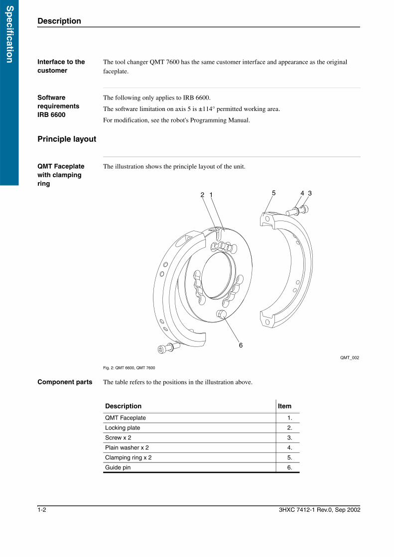
QMT Faceplate with clamping ring
The illustration shows the principle layout of the unit.
Fig. 2: QMT 6600, QMT 7600
Component parts The table refers to the positions in the illustration above.
QMT_002
6
4 3512
Description Item
QMT Faceplate 1.
Locking plate 2.
Screw x 2 3.
Plain washer x 2 4.
Clamping ring x 2 5.
Guide pin 6.
Sp
ecif
icat
ion
Description
3HXC 7412-1 Rev.0, Sep 2002 1-3
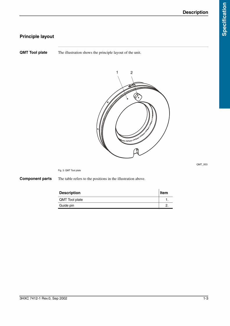
Principle layout
QMT Tool plate The illustration shows the principle layout of the unit.
Fig. 3: QMT Tool plate
Component parts The table refers to the positions in the illustration above.
QMT_003
1 2
Description Item
QMT Tool plate 1.
Guide pin 2.

Description
1-4 3HXC 7412-1 Rev.0, Sep 2002
Sp
ecification
Sp
ecif
icat
ion
Safety instructions
3HXC 7412-1 Rev.0, Sep 2002 1-5
Chapter 2: Safety instructions
Description
There are safety instructions in this chapter for all steps that involve a risk of personal injury or
material damage. In addition, they are written out by the instruction for each step.
General warnings where the intention is to avoid difficulties are only set out by the instruction in
question.
Personal injury or damage to the product may result if the safety instructions or the local safety
directives are not observed.
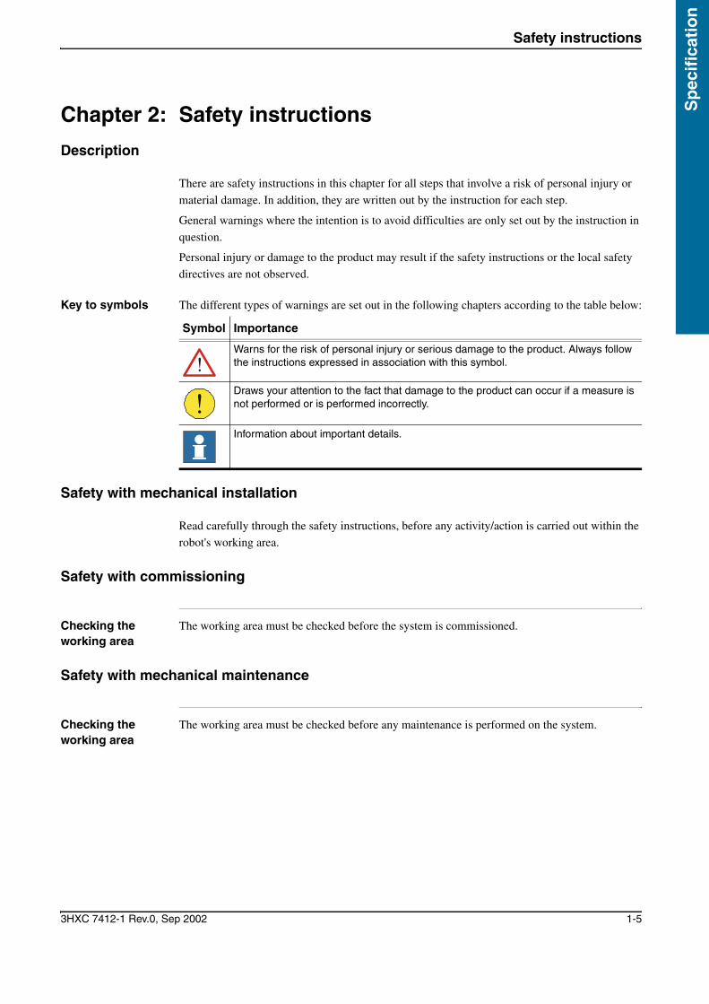
Key to symbols The different types of warnings are set out in the following chapters according to the table below:
Safety with mechanical installation
Read carefully through the safety instructions, before any activity/action is carried out within the
robot's working area.
Safety with commissioning
Checking the working area
The working area must be checked before the system is commissioned.
Safety with mechanical maintenance
Checking the working area
The working area must be checked before any maintenance is performed on the system.
Symbol Importance
Warns for the risk of personal injury or serious damage to the product. Always follow the instructions expressed in association with this symbol.
Draws your attention to the fact that damage to the product can occur if a measure is not performed or is performed incorrectly.
Information about important details.

Safety instructions
1-6 3HXC 7412-1 Rev.0, Sep 2002
Sp
ecification

Sp
ecif
icat
ion
Technical specifications and requirements
3HXC 7412-1 Rev.0, Sep 2002 1-7
Chapter 3: Technical specifications and requirements
Technical data
Performance QMT 6600/175
The table below contains important technical and performance data for the manual changer
QMT 6600/175.
Performance QMT 6600/225
The table below contains important technical and performance data for the manual changer
QMT 6600/225.
Performance QMT 7600
The table below contains important technical and performance data for the manual changer
QMT 7600.
Dimensions
The table below specifies the dimensions of the manual changers QMT 6600/7600.
Function Weight
Faceplate 4.6 kg
Tool plate 4.5 kg
Clamping ring x 2 2.2 kg/each
Function Weight
Faceplate 4.6 kg
Tool plate 4.5 kg
Clamping ring x 2 2.2 kg/each
Function Weight
Faceplate 8.5 kg
Tool plate 8.5 kg
Clamping ring x 2 3.1 kg/each
Component Dimensions
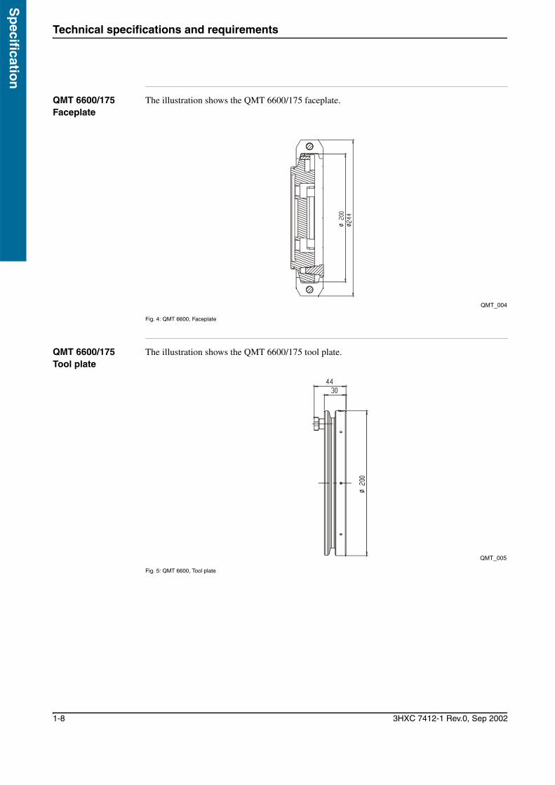
Faceplate 6600/175 D = 200 mm, t = 37
Faceplate 6600/225 D = 200 mm, t = 37
Faceplate 7600 D = 250 mm, t = 44.5
Clamping ring 6600/175 D = 244 mm, t = 42
Clamping ring 6600/225 D = 244 mm, t = 42
Clamping ring 7600 D = 300 mm, t = 42
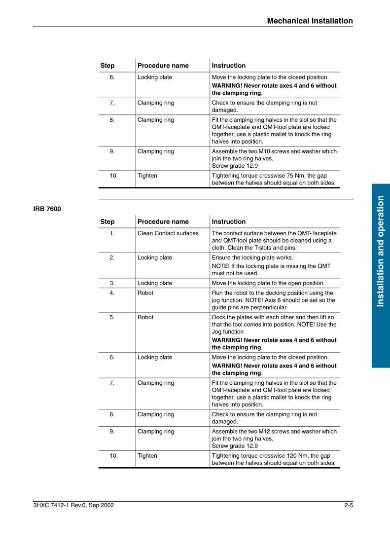
Tool plate 6600/175 D = 244 mm, t = 30
Tool plate 6600/225 D = 244 mm, t = 30
Tool plate 7600 D = 300 mm, t = 37
Technical specifications and requirements
1-8 3HXC 7412-1 Rev.0, Sep 2002
Sp
ecification
QMT 6600/175 Faceplate
The illustration shows the QMT 6600/175 faceplate.
Fig. 4: QMT 6600, Faceplate
QMT 6600/175 Tool plate
The illustration shows the QMT 6600/175 tool plate.
Fig. 5: QMT 6600, Tool plate
QMT_004
QMT_005

Sp
ecif
icat
ion
Technical specifications and requirements
3HXC 7412-1 Rev.0, Sep 2002 1-9
QMT 6600/225Faceplate
The illustration shows the QMT 6600/225 faceplate.
Fig. 6: QMT 6600/225, Faceplate
QMT 6600/225 Tool plate
The illustration shows the QMT 6600/225 tool plate.
Fig. 7: QMT 6600/225, Tool plate
QMT_006
QMT_007

Technical specifications and requirements
1-10 3HXC 7412-1 Rev.0, Sep 2002
Sp
ecification
QMT 7600 Faceplate
The illustration shows the QMT 7600 faceplate.
Fig. 8: QMT 7600, Faceplate
QMT 7600Tool plate
The illustration shows the QMT 7600 tool plate.
Fig. 9: QMT 7600, Tool plate
QMT_008
37
QMT_009

Sp
ecif
icat
ion
Variants (and options)
3HXC 7412-1 Rev.0, Sep 2002 1-11
Chapter 4: Variants (and options)
Variants (and options) for QMT 6600, QMT 7600
Ordering list The tables describe the variants (and options) that can be order for QMT 6600, QMT 7600.
QMT 6600/175 Name Part. no.
Faceplate, assembly 3HXC 0100-384
Clamping ring, assembly 3HXC 0100-386
Tool plate, assembly 3HXC 0000-153
QMT 6600/225 Name Part. no.
Faceplate, assembly 3HXC 0100-387
Clamping ring, assembly 3HXC 0100-386
Tool plate, assembly 3HXC 0000-153
QMT 7600 Name Part. no.
Faceplate, assembly 3HXC 0100-388
Clamping ring, assembly 3HXC 0100-390
Tool plate, assembly 3HXC 0000-154

Variants (and options)
1-12 3HXC 7412-1 Rev.0, Sep 2002
Sp
ecification

3HXC 7412-1 Rev.0, Sep 2002 Installation and operation i
Inst
alla
tio
n a
nd
op
erat
ion
Flap 2: Installation and operationChapter 1: Unpacking and handling 1
Safety 1General 1Acceptance inspection 1Cleaning 1
Chapter 2: Mechanical installation 3
Dismantle the faceplate from the robot 3IRB 6600 3IRB 7600 3
Assembling the QMT-Faceplate, 3IRB 6600 3 IRB 7600 3
Assembling the QMT-tool plate 3QMT 6600 3QMT 7600 4
Docking the tool 4IRB 6600 4IRB 7600 5

Installation and operation ii 3HXC 7412-1 Rev.0, Sep 2002
Installatio
n an
d o
peratio
n

Inst
alla
tio
n a
nd
op
erat
ion
Unpacking and handling
3HXC 7412-1 Rev.0, Sep 2002 2-1
Chapter 1: Unpacking and handling
Safety
GeneralRead through this chapter before using QMT.
Wear protective footwear with all handling of heavy objects.
Always lift heavy equipment according to the stipulated codes of practice.
Always attempt to find the most comfortable working height/working position.
Acceptance inspection
Check using the list of items that all components parts have been included in the delivery.
Check that no visible damage has occurred during transport.
Test assemble to ensure no damage has occurred during transport.
CleaningClean all components using a cloth and white spirit before assembly.

Unpacking and handling
2-2 3HXC 7412-1 Rev.0, Sep 2002
Installatio
n an
d o
peratio
n

Inst
alla
tio
n a
nd
op
erat
ion
Mechanical installation
3HXC 7412-1 Rev.0, Sep 2002 2-3
Chapter 2: Mechanical installation
Dismantle the faceplate from the robot
IRB 6600 To dismantle the faceplate from the robot, refer to the Maintenance Manual for IRB 6600.
IRB 7600 To dismantle the faceplate from the robot, refer to the Maintenance Manual for IRB 7600.
Assembling the QMT-Faceplate,
IRB 6600 Assemble the QMT-Faceplate according to the instruction, refer to the Maintenance Manual for
IRB 6600.
IRB 7600 Assemble the QMT-Faceplate according to the instruction, refer to the Maintenance Manual for
IRB 7600.
Assembling the QMT-tool plate
Tools • Torque wrench:
• Hexagonal insert M12:
QMT 6600 Assembling the tool plate on the tool
WARNING! Ensure the faceplate is tightened on the robot to the specified torque. See the robot's Installation Manual for the faceplate torque.
Step Procedure name Instruction
1 Tools and tool plate Carefully clean the contact surfaces
2 Assemble QMT 6600 Assemble the stated number of screws/washers in the joint. NOTE! assemble the plate so that the holes for the guide pins are perpendicular, this makes docking easier.
NOTE! The screw length must not be longer than the thickness of the tool + 15 mm.
3 Tightening Tighten the joint to the applicable torque
4 Visual inspection Ensure the joint is secure. The guide pin must be located, see page 1-2

Mechanical installation
2-4 3HXC 7412-1 Rev.0, Sep 2002
Installatio
n an
d o
peratio
n
QMT 7600 Assembling the tool plate on the tool
Docking the tool
Tools • Plastic mallet:
• Torque wrench:
• Hexagonal insert M10:
IRB 6600
Step Procedure name Instruction
1 Tools and tool plate Carefully clean the contact surfaces
2 Assemble QMT 7600 Assemble the stated number of screws/washers in the joint. NOTE! assemble the plate so that the holes for the guide pins are perpendicular, this makes docking easier.
NOTE! The screw length must not be longer than the thickness of the tool + 20 mm.
3 Tightening Tighten the joint to the applicable torque
4 Visual inspection Ensure the joint is secure. The guide pin must be located, see page 1-2
WARNING! The robot must not be run without the clamping ring
WARNING! Rotation of axes 4 and 6 before the clamping ring is fitted can cause the tool to release.
WARNING! Ensure the tool plate and tool are tightened to the specified torque.
Step Procedure name Instruction
1. Clean Contact surfaces The contact surface between the QMT- faceplate and QMT-tool plate should be cleaned using a cloth. Clean the T-slots and pins.
2. Locking plate Ensure the locking plate works.
NOTE! If the locking plate is missing the QMT must not be used.
3. Locking plate Move the locking plate to the open position.
4. Robot Run the robot to the docking position using the jog function. NOTE! axis 6 should be set so the guide pins are perpendicular.
5. Robot Dock the plates with each other and then lift so that the tool comes into position. NOTE! Use the Jog function
WARNING! Never rotate axes 4 and 6 without the clamping ring.
Inst
alla
tio
n a
nd
op
erat
ion
Mechanical installation
3HXC 7412-1 Rev.0, Sep 2002 2-5
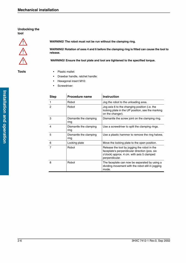
IRB 7600
6. Locking plate Move the locking plate to the closed position. WARNING! Never rotate axes 4 and 6 without the clamping ring.
7. Clamping ring Check to ensure the clamping ring is not damaged.
8. Clamping ring Fit the clamping ring halves in the slot so that the QMT-faceplate and QMT-tool plate are locked together, use a plastic mallet to knock the ring halves into position.
9. Clamping ring Assemble the two M10 screws and washer which join the two ring halves. Screw grade 12.9
10. Tighten Tightening torque crosswise 75 Nm, the gap between the halves should equal on both sides.
Step Procedure name Instruction
Step Procedure name Instruction
1. Clean Contact surfaces The contact surface between the QMT- faceplate and QMT-tool plate should be cleaned using a cloth. Clean the T-slots and pins.
2. Locking plate Ensure the locking plate works.
NOTE! If the locking plate is missing the QMT must not be used.
3. Locking plate Move the locking plate to the open position.
4. Robot Run the robot to the docking position using the jog function. NOTE! Axis 6 should be set so the guide pins are perpendicular.
5. Robot Dock the plates with each other and then lift so that the tool comes into position. NOTE! Use the Jog function WARNING! Never rotate axes 4 and 6 without the clamping ring.
6. Locking plate Move the locking plate to the closed position. WARNING! Never rotate axes 4 and 6 without the clamping ring.
7. Clamping ring Fit the clamping ring halves in the slot so that the QMT-faceplate and QMT-tool plate are locked together, use a plastic mallet to knock the ring halves into position.
8. Clamping ring Check to ensure the clamping ring is not damaged.
9. Clamping ring Assemble the two M12 screws and washer which join the two ring halves. Screw grade 12.9
10. Tighten Tightening torque crosswise 120 Nm, the gap between the halves should equal on both sides.
Mechanical installation
2-6 3HXC 7412-1 Rev.0, Sep 2002
Installatio
n an
d o
peratio
n
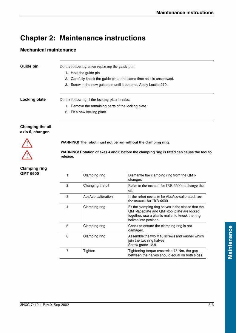
Undocking the tool
Tools • Plastic mallet:
• Drawbar handle, ratchet handle:
• Hexagonal insert M10:
• Screwdriver:
WARNING! The robot must not be run without the clamping ring.
WARNING! Rotation of axes 4 and 6 before the clamping ring is fitted can cause the tool to release.
WARNING! Ensure the tool plate and tool are tightened to the specified torque.
Step Procedure name Instruction
1 Robot Jog the robot to the unloading area.
2 Robot Jog axis 6 to the changing position (i.e. the locking plate in the UP position, see the marking on the changer).
3 Dismantle the clamping ring
Dismantle the screw joint on the clamping ring.
4 Dismantle the clamping ring
Use a screwdriver to split the clamping rings.
5 Dismantle the clamping ring
Use a plastic hammer to remove the ring halves.
6 Locking plate Move the locking plate to the open position.
7 Robot Release the tool by jogging the robot in the faceplate's perpendicular direction (pos. six o'clock) approx. 4 cm. with axis 5 clamped perpendicular.
8 Robot The faceplate can now be separated by using a dividing movement with the robot still in jogging mode.

3HXC 7412-1 Rev.0, Sep 2002 Maintenance i
Mai
nte
nan
ce
Flap 3: MaintenanceChapter 1: Maintenance intervals 1
Routine checks and preventive maintenance 1Maintenance chart 1
Chapter 2: Maintenance instructions 3
Mechanical maintenance 3Guide pin 3Locknig plate 3Clamping ring QMT 6600 3
Chapter 3: Spare parts 5
Spare parts for QMT 6600/175 5Faceplate 5Clamping ring 6Tool plate 7
Spare parts for QMT 6600/225 8Faceplate 8Clamping ring 9Tool plate 10
Spare parts for QMT 7600 11Faceplate 11Clamping ring 12Tool plate 13
Locking plate 14QMT 6600 14QMT 7600 14

Maintenance ii 3HXC 7412-1 Rev.0, Sep 2002
Main
tenan
ce

Mai
nte
nan
ce
Maintenance intervals
3HXC 7412-1 Rev.0, Sep 2002 3-1
Mai
nte
nan
ce
Chapter 1: Maintenance intervals
Routine checks and preventive maintenance
Maintenance chart
The changer is designed to need a minimum of maintenance. However, routine checks and
preventive maintenance always need to be carried out at regular intervals.
The maintenance chart describes the routine maintenance and routine checks in chronological
order.
.
Fig. 1: QMT 6600 and 7600, maintenance
Interval Part Maintenance More info.
With each change
Guide pin Visual inspection
Locking plate Cleaning, lubrication
Discs Visual inspection
Every six months Screw, clamping rings Check the torque See Chapter 2:Mechanical installation
Clamping ring
Tool plate
Clamping ring
Faceplate
QMT_010

Maintenance intervals
3-2 3HXC 7412-1 Rev.0, Sep 2002
Main
tenan
ce
Mai
nte
nan
ce
Maintenance instructions
3HXC 7412-1 Rev.0, Sep 2002 3-3
Mai
nte
nan
ce
Chapter 2: Maintenance instructions
Mechanical maintenance
Guide pin Do the following when replacing the guide pin:
1. Heat the guide pin
2. Carefully knock the guide pin at the same time as it is unscrewed.
3. Screw in the new guide pin until it bottoms. Apply Loctite 270.
Locking plate Do the following if the locking plate breaks:
1. Remove the remaining parts of the locking plate.
2. Fit a new locking plate.
Changing the oil axis 6, changer.
Clamping ring QMT 6600
WARNING! The robot must not be run without the clamping ring.
WARNING! Rotation of axes 4 and 6 before the clamping ring is fitted can cause the tool to release.
1. Clamping ring Dismantle the clamping ring from the QMT-changer.
2. Changing the oil Refer to the manual for IRB 6600 to change the oil.
3. AbsAcc-calibration If the robot needs to be AbsAcc-calibrated, see the manual for IRB 6600.
4. Clamping ring Fit the clamping ring halves in the slot so that the QMT-faceplate and QMT-tool plate are locked together, use a plastic mallet to knock the ring halves into position.
5. Clamping ring Check to ensure the clamping ring is not damaged.
6. Clamping ring Assemble the two M10 screws and washer which join the two ring halves. Screw grade 12.9
7. Tighten Tightening torque crosswise 75 Nm, the gap between the halves should equal on both sides.

Maintenance instructions
3-4 3HXC 7412-1 Rev.0, Sep 2002
Main
tenan
ce
Clamping ring QMT 7600 1. Clamping ring Dismantle the clamping ring from the QMT-
changer.
2. Changing the oil Refer to the manual for IRB 7600 to change the oil.
3. AbsAcc-calibration If the robot needs to be AbsAcc-calibrated, see the manual for IRB 7600.
4. Clamping ring Fit the clamping ring halves in the slot so that the QMT-faceplate and QMT-tool plate are locked together, use a plastic mallet to knock the ring halves into position.
5. Clamping ring Check to ensure the clamping ring is not scored.
6. Clamping ring Assemble the two M12 screws and washer which join the two ring halves. Screw grade 12.9
7. Tighten Tightening torque crosswise 120 Nm, the gap between the halves should equal on both sides.

Mai
nte
nan
ce
Spare parts
3HXC 7412-1 Rev.0, Sep 2002 3-5
Mai
nte
nan
ce
Chapter 3: Spare parts
Spare parts for QMT 6600/175
Faceplate Spare parts for QMT 6600/175, Faceplate
Fig. 2: 1QMT 6600/175 Faceplate
Quantity Description Art. no. Item
Faceplate assembly 3HXC 0100-384
1 Faceplate 3HXC 1000-170 1
1 Guide pin 3HXC 1000-171 2
1 Locking plate 3HXC 0100-385 3
1 Cylindrical pin 3ABA 107-7 4
1
2
3,4
QMT_011
Spare parts
3-6 3HXC 7412-1 Rev.0, Sep 2002
Main
tenan
ce
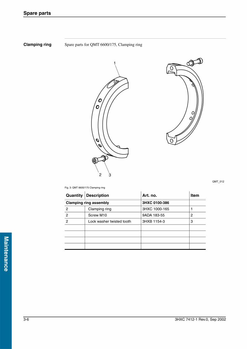
Clamping ring Spare parts for QMT 6600/175, Clamping ring
Fig. 3: QMT 6600/175 Clamping ring
Quantity Description Art. no. Item
Clamping ring assembly 3HXC 0100-386
2 Clamping ring 3HXC 1000-165 1
2 Screw M10 9ADA 183-55 2
2 Lock washer twisted tooth 3HXB 1154-3 3
32
1
QMT_012

Mai
nte
nan
ce
Spare parts
3HXC 7412-1 Rev.0, Sep 2002 3-7
Mai
nte
nan
ce
Tool plate Spare parts for QMT 6600/175, Tool plate:
Fig. 4: QMT 6600/175 Tool plate
Quantity Description Art. no. Item
QMT Tool plate assembly 3HXC 0000-153
1 QMT Tool plate 3HXC 1000-166 1
1 Guide pin 3HXC 1000-171 2
1 2
QMT_013

Spare parts
3-8 3HXC 7412-1 Rev.0, Sep 2002
Main
tenan
ce
Spare parts for QMT 6600/225
Faceplate Spare parts for QMT 6600/225, Faceplate
Fig. 5: QMT 6600/225 Faceplate
Quantity Description Art. no. Item
Faceplate assembly 3HXC 0100-387
1 Faceplate 3HXC 1000-175 1
1 Guide pin 3HXC 1000-171 2
1 Locking plate 3HXC 0100-385 3
1 Cylindrical pin 9ABA 107-7 4
1
2
3,4
QMT_014

Mai
nte
nan
ce
Spare parts
3HXC 7412-1 Rev.0, Sep 2002 3-9
Mai
nte
nan
ce
Clamping ring Spare parts for QMT 6600/225, Clamping ring
Fig. 6: QMT 6600/225 Clamping ring
Quantity Description Art. no. Item
Clamping ring assembly 3HXC 0100-386
2 Clamping ring 3HXC 1000-165 1
2 Screw M10 9ADA 183-55 2
2 Washer 3HXB 1154-3 3
32
1
QMT_015

Spare parts
3-10 3HXC 7412-1 Rev.0, Sep 2002
Main
tenan
ce
Tool plate Spare parts for QMT 6600/225, Tool plate
Fig. 7: QMT 6600/225 Tool plate
Quantity Description Art. no. Item
QMT Tool plate assembly 3HXC 0000-153
1 QMT Tool plate 3HXC 1000-166 1
1 Guide pin 3HXC 1000-171 2
1 2
QMT_016

Mai
nte
nan
ce
Spare parts
3HXC 7412-1 Rev.0, Sep 2002 3-11
Mai
nte
nan
ce
Spare parts for QMT 7600
Faceplate Spare parts for QMT 7600, Faceplate
Fig. 8: QMT 7600 Faceplate
Quantity Description Art. no. Item
Faceplate assembly 3HXC 0100-388
1 Faceplate 3HXC 1000-167 1
1 Guide pin 3HXC 1000-168 2
1 Locking plate assembly 3HXC 0100-389 3
1 Cylindrical pin 9ABA 107-8 4
1
2
3,4
QMT_017
Spare parts
3-12 3HXC 7412-1 Rev.0, Sep 2002
Main
tenan
ce
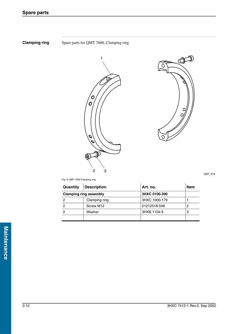
Clamping ring Spare parts for QMT 7600, Clamping ring
Fig. 9: QMT 7600 Clamping ring
Quantity Description Art. no. Item
Clamping ring assembly 3HXC 0100-390
2 Clamping ring 3HXC 1000-179 1
2 Screw M12 21212518-546 2
2 Washer 3HXB 1154-5 3
32
1
QMT_018

Mai
nte
nan
ce
Spare parts
3HXC 7412-1 Rev.0, Sep 2002 3-13
Mai
nte
nan
ce
Tool plate Spare parts for QMT 7600, Tool plate
Fig. 10: QMT 7600 Tool plate
Quantity Description Art. no. Item
QMT Tool plate assembly 3HXC 0000-154
1 QMT Tool plate 3HXC 1000-180 1
1 Guide pin 3HXC 1000-168 2
1 2
QMT_019
Spare parts
3-14 3HXC 7412-1 Rev.0, Sep 2002
Main
tenan
ce
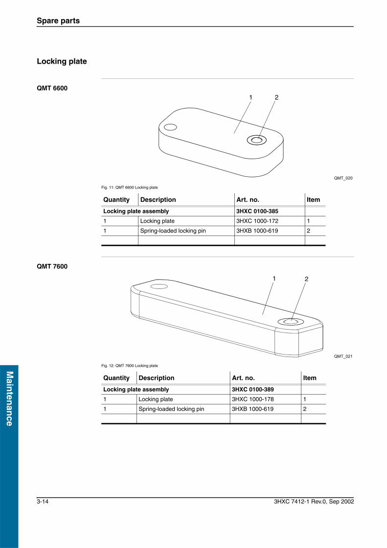
Locking plate
QMT 6600
Fig. 11: QMT 6600 Locking plate
QMT 7600
Fig. 12: QMT 7600 Locking plate
Quantity Description Art. no. Item
Locking plate assembly 3HXC 0100-385
1 Locking plate 3HXC 1000-172 1
1 Spring-loaded locking pin 3HXB 1000-619 2
1 2
QMT_020
Quantity Description Art. no. Item
Locking plate assembly 3HXC 0100-389
1 Locking plate 3HXC 1000-178 1
1 Spring-loaded locking pin 3HXB 1000-619 2
1 2
QMT_021


3HXC 7412-1 Rev.0, Sep 2002


