142
DYNATORCH CNC PLASMA CUTTER Software Users Manual Volume 1

DYNATORCH CNC PLASMA CUTTER
Software Users
Manual
Volume
1

DYNATORCH CNC PLASMA SYSTEMS
A Guide to the Software Features
Dynatorch Corporation2720 A Bridge St
Paducah, KY 42003Sales 877-260-2390 • Support 270-442-0560

Dyn
ator
ch C
NC
Pla
sma
Cut
ters
Table of ContentsIntroduction........................................................................................8
CNC Plasma Cutting 101...................................................................................................9Quick Machine Parameters Setup..................................................................................12
Hard stop installation for Hard Stop Homing.........................................................................................12Machine Settings Tab...........................................................................................................................12Inputs Tab.............................................................................................................................................13Homing Tab..........................................................................................................................................13Tuning Tab...........................................................................................................................................13Advanced Settings Tab.........................................................................................................................13Torch Tab.............................................................................................................................................14Joystick Tab..........................................................................................................................................14Offsets Tab...........................................................................................................................................14Drive Direction and Homing..................................................................................................................16Drive Distance calibration and Speed Setting.......................................................................................16Running your first Cycle........................................................................................................................17
Machine Parameter Settings...........................................................19Machine Tab.....................................................................................................................20
Comports..............................................................................................................................................20Buffer size.............................................................................................................................................20Max Angle.............................................................................................................................................20Units.....................................................................................................................................................20Work area Plus Limit+..........................................................................................................................21Work area Minus Limit-.........................................................................................................................21Scaling (encoder pulses per inch).........................................................................................................21Max Velocity.........................................................................................................................................21Max Acceleration during Rapid and Jog moves....................................................................................21Max Acceleration during Cutting moves...............................................................................................22Max Motor RPM....................................................................................................................................22
Inputs Tab........................................................................................................................23Outputs Tab..................................................................................................................... 25Homing Tab......................................................................................................................27
Homing Order.......................................................................................................................................27Home Method.......................................................................................................................................27Opposite Home Direction......................................................................................................................27Ignore Index Mark.................................................................................................................................27Home Velocity......................................................................................................................................27Home Offset.........................................................................................................................................28Home Value..........................................................................................................................................28The Homing Procedure.........................................................................................................................28
Tuning Tab.......................................................................................................................29K Proportional.......................................................................................................................................29K Derivative..........................................................................................................................................29K Integral..............................................................................................................................................29K Accel Feed Forward..........................................................................................................................29K Integrator Limit..................................................................................................................................29Error Limit (Following Error limit)..........................................................................................................29Sample rate..........................................................................................................................................29K Velocity Feed forward........................................................................................................................29K Gravity...............................................................................................................................................30AMPS value (1-1023)...........................................................................................................................30Additional Parameters..........................................................................................................................30
Special M-Codes Tab......................................................................................................31M86 ... M91...........................................................................................................................................31M80 ... M85...........................................................................................................................................31
Advanced Tab..................................................................................................................32Ask to Home at startup.........................................................................................................................32Show User Defined M-Code Button......................................................................................................32If no Feed rate is set, use this default value..........................................................................................32
2

Dyn
ator
ch C
NC
Pla
sma
Cut
ters
Allow Re-Zeroing in G53 (machine coordinates)..................................................................................32Keyboard character turns on / off an output..........................................................................................32These Outputs turn OFF when the Servo Errors..................................................................................33Feed Hold Turns these Outputs OFF....................................................................................................33Resume turns these Outputs ON..........................................................................................................33Wait for M50 before resuming (Input port B on X axis).........................................................................33Do not reset line number when clearing E-Stop condition....................................................................33Start Cycle with Line Number >1 forces these Outputs ON..................................................................33M30 (end of program) turns these Outputs OFF...................................................................................33Zoom All if rapid move exits the current zoomed in screen...................................................................33Vector Slow Proportional Up To XX.X Degrees (89 degrees max).......................................................33Continuous Path...................................................................................................................................34Slow at Vertex......................................................................................................................................34Allowable Overshoot:............................................................................................................................35Minimum arc radius allowed.................................................................................................................35Max allowed comm errors before alarming...........................................................................................35E-Stop abruptly halts motors instead of decelerating to a stop.............................................................35Use APS (automatic proportional slowdown) for short segments.........................................................35Freeze THC during these short cut paths.............................................................................................35Show Sub-Routines in G-Code Box......................................................................................................35Enable View option - Show Positions...................................................................................................35Ghost Image Color choices (cutting / rapid)..........................................................................................36Cutting Path Line Thickness and color.................................................................................................36Numeric display color...........................................................................................................................36
Torch Tab.........................................................................................................................37Scaled arc voltage input.......................................................................................................................37Down force used when searching for the plate.....................................................................................37AVC Height sensing delay (0.25 to 2.0 seconds)..................................................................................37AVC Correction Sensitivity Factor.........................................................................................................38AVC # of Measurements to Average....................................................................................................38Fixed distance jogging with the torch....................................................................................................38While cutting, each click of the torch jog button will move....................................................................38Number of seconds to wait for the arc to establish before it is an error................................................38Delay time after arc is established and before starting gantry movement, for arc to pierce thick material.............................................................................................................................................................39Raise the torch between cuts in OxyFuel mode....................................................................................39Using Jog buttons during a cycle will re-teach the cutting height..........................................................39Pause at pierce height before going to cut height for preheating..........................................................39This output turns ON for OxyFuel Cutting Oxygen................................................................................39This output turns ON for OxyFuel Preheat Gas....................................................................................39Leave preheat gas output on between cuts..........................................................................................39
Offsets Tab....................................................................................................................... 40Service and Load Positions..................................................................................................................400,0 Position...........................................................................................................................................40Raise torch first when "Service pos" button is pressed.........................................................................40Raise torch first when "Load pos" button is pressed.............................................................................40Raise torch first when "0,0 pos" button is pressed................................................................................40G54... G57............................................................................................................................................40
Joystick Tab.....................................................................................................................42Enable the Joystick...............................................................................................................................42Reverse X Dir.......................................................................................................................................42Reverse Y Dir.......................................................................................................................................42Use velocity mode for freehand joystick. The freehand joystick is the one on the LEFT......................42Maximum freehand cutting speed.........................................................................................................43Joy Stick Buttons..................................................................................................................................43Joy Stick Button #12.............................................................................................................................43Joystick Use.........................................................................................................................................43Straight Line Cutting.............................................................................................................................44
Maintenance Tab.............................................................................................................45Query Motor Information.......................................................................................................................45Erase Program in Motor(s)...................................................................................................................45
Terminal Tab.................................................................................................................... 46Send to.................................................................................................................................................46Current motor information.....................................................................................................................46Continuous update and refresh:............................................................................................................47
Files Tab........................................................................................................................... 48File Open Extensions............................................................................................................................48
Custom Tab...................................................................................................................... 49
3
Dyn
ator
ch C
NC
Pla
sma
Cut
ters
The Main Cutting Screen Controls.................................................50Menu Options...................................................................................................................51
Under File:............................................................................................................................................51Open G-Code File................................................................................................................51Edit G-Code and New G-Code (sub) Bank and New Subroutine..........................................51New G-Code (sub) Code Wizard..........................................................................................51Save.....................................................................................................................................51Save As................................................................................................................................51Convert DXF - G-Code.........................................................................................................51Exit Program.........................................................................................................................51
Under Setup:........................................................................................................................................51Manually Set Home..............................................................................................................52Search for Home..................................................................................................................52Clear homed flags................................................................................................................52Machine Settings..................................................................................................................52
Under SmartMotor:...............................................................................................................................52Under View:..........................................................................................................................................52Under Help:..........................................................................................................................................52
About....................................................................................................................................52Contents...............................................................................................................................52
The Numeric Display.......................................................................................................53ALL ON button......................................................................................................................................53Axis label Checkbox (X,Y,Z).................................................................................................................53Status Error Indicators:.........................................................................................................................53The Master Slave Button (M and S on the button next to the X numeric display).................................53Coordinate systems..............................................................................................................................53
The Jogging Window.......................................................................................................55X- X+ Y+ Y- Buttons.....................................................................................................................55Continuous...........................................................................................................................................55Fixed.....................................................................................................................................................55Keyboard Jogging.................................................................................................................................55STOP....................................................................................................................................................55Joystick.................................................................................................................................................55Torch + Torch –...................................................................................................................................55Torch CUT / No-CUT and THC (height control)....................................................................................56
Start Functions................................................................................................................57Open Button.........................................................................................................................................57Edit Button............................................................................................................................................57Start Cycle / Step Buttons.....................................................................................................................57Feed Hold Button..................................................................................................................................57Resume Button.....................................................................................................................................57Reset Button.........................................................................................................................................57Feed rate and Rapid overrides.............................................................................................................58Dis-connect / Connect..........................................................................................................................58
Program line number boxes...........................................................................................58Manual data input line (MDI line)....................................................................................59User defined / dedicated positions buttons..................................................................60
Home Pos button..................................................................................................................................60Load Pos and Service Pos buttons.......................................................................................................60Raise Torch button...............................................................................................................................600,0 Pos button......................................................................................................................................60Zero X-Y button....................................................................................................................................60E-Stop Assist button.............................................................................................................................60Zoom All and the Arrow (next to Zoom All) buttons..............................................................................61
Plasma / Oxyfuel cutting selection................................................................................62Plasma Cutting THC functions..............................................................................................................62Oxyfuel Cutting functions......................................................................................................................62Oxyfuel torch types and connections....................................................................................................63Torch CUT / No-CUT and THC (height control)....................................................................................63
The Visual Cutting Area..................................................................................................65
The DXF to G-Code Converter........................................................68Creating a G-Code File from a DXF drawing.................................................................69
4

Dyn
ator
ch C
NC
Pla
sma
Cut
ters
How it works.........................................................................................................................70Saving and Saving Special...................................................................................................................70Scale the object with this ratio xxx to 1.................................................................................................71Save as an Array of Parts.....................................................................................................................71
DXF Converter Setup Menu............................................................................................73The Settings Tab..................................................................................................................................73Join Tolerance......................................................................................................................................73After conversion, save *.dxf as *.tap.....................................................................................................73Set G92 to initial position......................................................................................................................73Use these Z commands when Points are encountered in the drawing.................................................73The Import Locations Tab.....................................................................................................................74
Co-Locate with Origin as drawn............................................................................................74Locate drawing “Zero” at X.xxx Y.yyy................................................................................74Lower Left Extents at X.xxx Y.yyy......................................................................................74Use Current Position.............................................................................................................74
The Conversions (Plasma, OxyFuel, Custom) Tabs.............................................................................75PreCode...............................................................................................................................65PostCode..............................................................................................................................65Z up......................................................................................................................................65Z Down.................................................................................................................................65
Modifying an Existing G-Code File.................................................66Modifying a G-Code.........................................................................................................67
Browse for a G-Code to Modify.............................................................................................................67Scaling / Moving...................................................................................................................................67
Scale Factor.........................................................................................................................68Allow scaling of the original XY starting point.......................................................................68Maintain original XY starting location when scaling..............................................................68Move starting XY location to X.xxx Y.yyy.............................................................................68Measuring the amount of material needed to cut this newly scaled shape...........................68Saving As.............................................................................................................................68
Rotating an object.................................................................................................................................68Degrees to Rotate................................................................................................................69Rotate about.........................................................................................................................69
Building an Array..................................................................................................................................69Columns...............................................................................................................................70The E Button.........................................................................................................................70Odd column spacing.............................................................................................................70Even column spacing............................................................................................................70Rows....................................................................................................................................70The E Button.........................................................................................................................70Odd row spacing...................................................................................................................70Even row spacing.................................................................................................................70
Special Array Options...........................................................................................................................71Stagger even rows................................................................................................................71Reduce even rows by 1........................................................................................................71Rotate object in even numbered rows..................................................................................71Rotate every other object in each rows.................................................................................72
Convert a G-Code file to DXF file.........................................................................................................72Include rapid (G0) moves as lines in the output file..............................................................73
Convert an EIA file to G-Code file.........................................................................................................73
The Code Wizard..............................................................................73Code Wizard.....................................................................................................................75
Brief Overview......................................................................................................................................75In Depth................................................................................................................................................75
Plasma or OxyFuel...............................................................................................................75Circle, Rectangle, Gusset, or Donut.....................................................................................75Clockwise or Counter Clockwise...........................................................................................76Include a Lead-in or Do Not include a Lead-in......................................................................76Fillets in the Corners UR (upper right) LL (lower left)............................................................76
Making an Circles or Donuts.................................................................................................................76Hole Center X.......................................................................................................................76Hole Center Y.......................................................................................................................76
5

Dyn
ator
ch C
NC
Pla
sma
Cut
ters
Feed Rate.............................................................................................................................77Outer Diameter.....................................................................................................................77
Making an Gussets...............................................................................................................................77X Start..................................................................................................................................77Y Start..................................................................................................................................77X Leg Length........................................................................................................................77Y Leg Length........................................................................................................................77Feed Rate.............................................................................................................................77Fillet radius...........................................................................................................................77
Making an Rectangular Shapes............................................................................................................77X Start..................................................................................................................................78Y Start..................................................................................................................................78X Width.................................................................................................................................78Y Height................................................................................................................................78Feed Rate.............................................................................................................................78Fillet radii..............................................................................................................................78
Making an ARRAY of Parts..................................................................................................................78Rectangular..........................................................................................................................78Circular.................................................................................................................................79
E-Stop Assistance............................................................................80E-Stop Assistant..............................................................................................................81
Joystick Cutting and Controls........................................................81Joystick Operation..........................................................................................................83
Enable the Joystick...............................................................................................................................83Reverse X Dir.......................................................................................................................................83Reverse Y Dir.......................................................................................................................................83Use velocity mode for freehand joystick...............................................................................................83Maximum freehand cutting speed.........................................................................................................84Joy Stick Buttons..................................................................................................................................84Joy Stick Button #12.............................................................................................................................84Joystick Use.........................................................................................................................................84Straight Line Cutting.............................................................................................................................84
Implemented G-Codes.....................................................................85G-Codes used in the CNC Plasma Cutter......................................................................86
G00 Rapid Motion.................................................................................................................86G01 Linear Motion................................................................................................................86G02 Clockwise Circular Arc..................................................................................................86G03 Counterclockwise Circular Arc......................................................................................87G04 Dwell.............................................................................................................................87G10 Coordinate System Reset.............................................................................................87G17 X-Y Plane Selection (This is the normal plane of operation).........................................87G20 and G70 Inch Mode......................................................................................................87G21 and G71 Metric Mode...................................................................................................87G23 Start Plasma Torch Cycle.............................................................................................87G24 Rapid Move of Torch to Commanded Position..............................................................88G25 End Plasma Torch Cycle..............................................................................................88G26 Turn ON the Automatic THC.........................................................................................88G27 Home Torch (seldom used or needed)..........................................................................88G28 Turn OFF the Automatic THC.......................................................................................88G53 G54 G55 G56 G57 Coordinate offsets..........................................................................88G76 Repeat a section of the program...................................................................................88G90 Absolute Mode..............................................................................................................89G91 Relative Mode...............................................................................................................89G92 Set Coordinate System Offset.......................................................................................89
Implemented M-Codes.....................................................................89M-Codes used in the CNC Plasma Cutter......................................................................91
6

Dyn
ator
ch C
NC
Pla
sma
Cut
ters
M0 Program Halt..................................................................................................................91M01 Program Pause.............................................................................................................91M02 End Program (See M30 below).....................................................................................91
M03 and M04 and M05 and M08 and M09:..........................................................................................91M14 Turn ON any single or multiple outputs.........................................................................91M15 Turn OFF any single or multiple outputs.......................................................................91M21 Continuous Path On.....................................................................................................91M210 Set Maximum Angle Amount......................................................................................91M22 Continuous Path Off.....................................................................................................91M23 Slow at Vertex On.........................................................................................................91M24 Slow at Vertex Off.........................................................................................................91M25 Px.xxx Sets the pierce delay time with the P Word......................................................92M26 Enables the THC for automatic arc voltage height sensing..........................................92M28 Disables the THC for automatic arc voltage height sensing..........................................92M30 & M02 Program End and Reset....................................................................................92M41 Turns on an output as soon as motion starts...............................................................92M42 Turns on an output as soon as motion starts...............................................................92M43 Turns on an output as soon as motion starts...............................................................92M45 Turns off output(s) immediately...................................................................................92M46 Turns off output(s) immediately...................................................................................92M47 Turns off output(s) immediately...................................................................................92M50... M57 Waiting for Inputs from the real world................................................................92M60... M73 Outputs to the real world....................................................................................92M80... M85 Special codes for advanced programmers, it does special motor command functions...............................................................................................................................93M86... M91 Special codes for sound functions.....................................................................93M95 Dwell (exactly the same as an G04).............................................................................93M98 Go To a Subroutine......................................................................................................93M99 Return from a Subroutine.............................................................................................93M100 Special Polishing routine............................................................................................94M101 Special Pause with optional instructions.....................................................................94
Wiring Harnesses.............................................................................94Single X drive Wiring Layout..........................................................................................95Dual X drive Wiring Layout.............................................................................................96
Grounding.........................................................................................96IMPORTANT GROUNDING TEST....................................................................................98
GROUND TEST PROCEDURE............................................................................................98
IntroductionIntroduction
Chapter
1
7

Dyn
ator
ch C
NC
Pla
sma
Cut
ters
Our CNC software is designed expressly for the Plasma and Oxyfuel Flame Cutting Industry to exploit the many technological advantages only available from our intelligent motors. New users and seasoned users alike will appreciate the ease of operation provided by this software.
Our CNC software can accept traditional G-code or drawings in a DXF file format. Objects created in many of different software packages are easily imported using DXF file formats.
The DXF Conversion screen of our software allows standard DXF files created by any CAD or drawing software to be imported, and converted into G-Code that is used to direct cutting operations. Additionally, the DXF files can be processed to optimize them for plasma and oxyfuel flame cutting.
The following two sections will help you get started.
CNC Plasma Cutting 101
A tutorial on Plasma Cutting
Quick Setup
A quick guide to get your plasma table set-up to the correct operating parameters
8

Dyn
ator
ch C
NC
Pla
sma
Cut
ters
CNC Plasma Cutting 101CNC Plasma Cutting 101CNC plasma cutting, like many other disciplines, has unique attributes and methods. We hope to give a new user some basics as an introduction to this fascinating and useful subject.
A plasma cutting machine typically takes ordinary compressed shop air, strips off its electrons converting it to a super hot ionized state (plasma). A hand held or machine operated torch projects the super hot plasma against the material to be cut. When the plasma hits the material it melts; the melted material is blown away by the force of the moving plasma leaving a hole or gap. By moving the torch across the material, a continuous gap is created much like one created by a saw blade. A hand held torch is limited in accuracy by the hand that holds it. A machine torch is a specialized torch designed to be held and moved by a computer controlled gantry system, which assures accuracy in complex cutting operations.
There are two types of CNC plasma cutting systems: Standard and High Definition. High Definition systems utilize the same ionized gas principle but different torch design and gas feeds. High Definition can produce cleaner, more precise cuts than standard plasma cutting systems but generally cost as much as $30,000. For the purpose of this discussion, we will stick to Standard plasma cutting at a small fraction of High Definition costs.
What can you do with a CNC Plasma Cutting Machine? Essentially, you can cut simple or complex shapes into any material that can conduct electricity. Typical materials would be common steels and aluminum. Non-typical materials might include brass or copper titanium (creates toxic fumes) with special provision for venting, vision protection and gas selection. Complex shapes can be cut into flat stock, tubing, angles etc. Cutting can be done rapidly, accurately and with repetition. Cutting parts for mechanical assemblies or artwork of great complexity can be accomplished with equal speed and accuracy.
Can you cut watch gears with a CNC plasma cutter? No, and you can’t engrave on diamonds either. The gas-like plasma removes material while it cuts much like a saw blade cutting a board. Like any device that removes material while cutting, plasma cutters have limitations on doing very small detailed work. However, small work without tiny inside radiuses is well within its capabilities. Additionally, formerly tedious tasks like locating a pattern of holes can be done through a series of pierces for later drilling to finished size. This can save many hours of layout work. We have cut a number of ¾” by ¾” parts with a located hole in the center many times. Because of its low cost and high versatility, plasma cutting has become a fabrication tool in thousands of shops.
How does an object go from a drawing to finished part? First there is software. CNC plasma cutting requires three basic types of software: creation, conversion/modification and execution.Creation software actually generates the drawing that will be cut. Parts for fabricated assemblies are created by CAD packages like AutoCAD, Turbo CAD and many others. These CAD systems have a universal export (interchange) format called DXF. Drawings produced in a DXF format can be easily imported into most plasma cutting systems. DXF drawings are in a vector format as opposed to a raster format. Vectors are lines of specific length and direction. Raster formatted drawings are made up of a series of dots. Bitmaps and “Gif” drawings would be examples of raster images. Although the human eye can interpret raster images, a CNC machine can not. Raster images must be converted to vector format. There are many ways to do this. Some methods are good, some bad. You can call us for a further discussion of this subject. AutoCAD, Turbo CAD, Corel, PhotoShop and dozens of others can provide you assistance in creating drawings suitable for importing into your plasma cutting system. Since excellent drawing creation software is available on the open market, we leave it up to the user to select what is best for their unique needs. If you need some help in that direction? Call us. We are anxious to help.
As mentioned, the plasma cutter removes material while cutting. The width of the cut, as an example, might be .040. If we center the cut on the parts edge, we will remove .020 off the part’s
9

Dyn
ator
ch C
NC
Pla
sma
Cut
ters
edge. This will produce an undersized part. If we offset the cut .020 into the waste side of the material the part will be properly cut. Specified offsets can be created in most good CAD packages.
At the start of each cut the plasma cutter makes an initial round pierce. From the pierce hole the CNC plasma cutter begins cutting its normal slot. If we were cutting out a box-shaped object and began with a pierce at one corner. The round pierce hole would nip off the corner a bit and leave that corner poorly formed. To prevent this, we pierce the material a short distance away from the object, start the cut and proceed into the object with a fully established, clean cutting arc. The cut from the pierce point to the beginning of the object is called a “lead in” (see figure 1). Similarly we want to terminate the arc away from the object, so we continue the arc a short distance beyond the normal completion point. This is called a: lead out.”
CNC machines move according to very specific instructions given to them. These instructions are in the form of a CNC machine programming language. This programming language is called G and M coding. Since the typical drawing input format is a DXF file we need some way to convert it to G/M code. Some CAD software can save a drawing directly in a G Code format skipping the need to convert a DXF file. As part of its structure our software provides a simple means of converting DXF files into G Code.
In addition to doing a G-Code conversion our software does much more. Typically a DXF drawing file generated by a CAD package needs a bit of “tuning up” to optimize it for CNC cutting. For example, a drawing may need to be joined. Picture a drawing of a box. The box may consist of four separate lines at right angles, or, it may consist of one line with four right angles. This is a big difference. The CNC Plasma cutter will interpret the separate line box as needing four independent cuts and will stop and restart at each corner. This will produce a sloppy part. The CNC cutter will cut the one line box differently. It will start at one corner and cut all around the box without stopping till it returns to where it started, which results in a much better part. Our software allows you to take separate lines, arcs, etc. and join them into one line entity for optimum cutting.
10

Dyn
ator
ch C
NC
Pla
sma
Cut
ters
A drawing may need to be sequenced. Imagine you want to cut a donut. If you cut the outside circle first, the part will drop out of the material stock and you will not have the opportunity to cut out the center hole. When a CAD program creates a drawing, the order the drawing parts were created in is the order they will be cut. In most cases the order they were created in will not be the order you want them to be cut. Our software allows you to reorder the cut sequence to your choices.
Once you are satisfied that your drawing is properly joined and sequenced, the software should be able to save it as a G-Code file. When the G-Code is created you have completed all the work needed on the drawing file and it is ready to cut.
The execution portion of the software will then process the G-Code into the drive components and cut your parts.
At this point we should discuss the steps involved in plasma cutting.
In the first step the torch needs to properly locate itself above the material. That the torch must be over the proper location to begin the first cut is obvious. What may not be as obvious is that the torch must also be the proper distance above the work. To do this the torch must locate the material in relation to itself. There are three basic types of material sensors the torch can use to “find” its initial height above the material. The three sensors are: a mechanical switch, proximity and pressure sensing. The torch positions itself over the starting point, lowers itself, finds the material using one of the three sensing methods, then raises itself to an optimal height for an initial material pierce. Do not confuse the pierce height and cutting height. The pierce height is larger than the cutting height. When piercing there is a momentary molten material splash. You want the torch tip high enough to avoid the splash fouling the torch tip, but close enough to make a clean pierce. Once the material is pierced and arc established the torch should lower itself to an optimal cutting height.
Maintaining the proper gap distance between the torch tip and material wile cutting is critical. Anyone stating otherwise is being less than honest with you. Material as received from the mill is not perfectly flat. Material that may be reasonably flat will bow somewhat while it is being cut from heat warpage. If the material to torch tip distance is not maintained within a few thousandths of an inch, regardless of the material’s flatness, the cut will be poor and torch tips will not last. Maintaining the proper distance is the job of an automated torch height controller. Without an automated torch height controller there is NO way to maintain proper cutting (arc) gap. Again, some type of automated torch height controller is essential from day one. The best types maintain cutting gap by monitoring arc voltage. The best types can set an initial pierce height and maintain a separate cutting gap distance. Of course, our torch height controller can do both exceedingly well.
The plasma cutting arc produces an angular cut called a kerf. This means the cut edge may not be perfectly perpendicular. The thicker the material that is cut the more pronounced the kerf angle appears. Kerf angularity can be minimized by keeping in mind this rule of thumb. Using our donut as an example, cut the outside circle in a clockwise direction. Cut the inside circle in a counter clockwise direction.
While a cut is being made some of the oxidized material removed by the plasma arc is not completely blown away. It sticks to the cut edge in droplet form. This material is called dross or slag. Dross is very brittle and is easily removed by tapping it with a small hammer, grinding or sanding it off. The amount of dross produced is a function of cut speed, torch tip condition, material cleanliness and material quality.
11

Dyn
ator
ch C
NC
Pla
sma
Cut
ters
Quick Machine Parameters SetupQuick Machine Parameters SetupBE SURE YOUR MONITOR IS SET FOR 1024 BY 768 DISPLAY MODE
This section includes step-by-step instructions for setting up your software and calibrating your machine for the servo drive software.
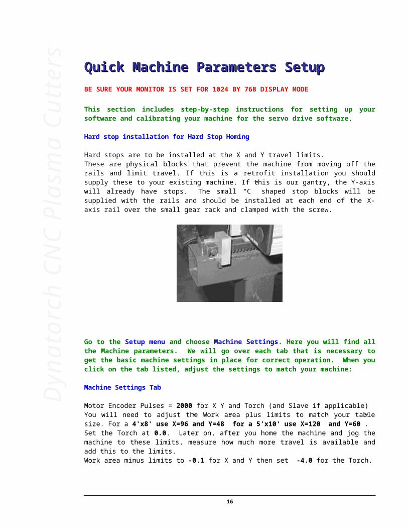
Hard stop installation for Hard Stop Homing
Hard stops are to be installed at the X and Y travel limits.These are physical blocks that prevent the machine from moving off the rails and limit travel. If this is a retrofit installation you should supply these to your existing machine. If this is our gantry, the Y-axis will already have stops. The small “C” shaped stop blocks will be supplied with the rails and should be installed at each end of the X-axis rail over the small gear rack and clamped with the screw.
Go to the Setup menu and choose Machine Settings. Here you will find all the Machine parameters. We will go over each tab that is necessary to get the basic machine settings in place for correct operation. When you click on the tab listed, adjust the settings to match your machine:
Machine Settings Tab
Motor Encoder Pulses = 2000 for X Y and Torch (and Slave if applicable)You will need to adjust the Work area plus limits to match your table size. For a 4'x8' use X=96”and Y=48” for a 5'x10' use X=120” and Y=60”. Set the Torch at 0.0. Later on, after you home the machine and jog the machine to these limits, measure how much more travel is available and add this to the limits.Work area minus limits to -0.1 for X and Y then set -4.0 for the Torch.Scaling with our 30 to 1 gear reducer X=-15275, Y=15275, Torch = -10000 (new)Scaling with our 28 to 1 gear reducer X=-14257, Y=14257, Torch = -10000 (old)If you have built your own gear drive system, please calculate the number of pulses it takes to move 1"... the motor encoder has 2000 pulses per revolution. Or press the "?" button for help with this calculation.Maximum Velocity please start with 12 inches per second for X and Y, 15 for TorchRapid Accel please start with 10 inches per second for X and Y, 12 for TorchCutting Accel please start with 4 inches per second for X and YIf any RPM indicates greater than 7000 rpm, you are destined to have failures. Please lower the maximum velocity, until you reach about 6000 rpm as a maximum.On Dual Drive units, never exceed 5000 rpm on the slave motor
12

Dyn
ator
ch C
NC
Pla
sma
Cut
ters
Inputs Tab
Go to Setup, choose Machine Settings and then select the Inputs tab. Adjust theses settings:
Port B input on X axis = Plasma Arc ConfirmationPort C input on X axis = Emergency StopAll other ports = Input does nothing
Homing Tab
Next, select the tab marked Homing and change these settings
X-axisOpposite is CheckedY-axisOpposite is UncheckedTorch axisOpposite is UncheckedAll axesVelocity is 3/4 fullIgnore in UncheckedTorque = 120Offset = 0.25Home Value = 0.0
Tuning Tab
Now select the tab marked Tuning and verify these settings
All AxesProportional gain = 30Derivative gain = 300Integral gain = 15Accel Feed forward = 0Integral limit = 100Follow error = 7000Sample rate = 1Velocity feed forward = 0Gravity compensation = 0AMPS = 1000Additional Parameters = F=8 (no spaces between F=8)
Advanced Settings Tab
Select the tab marked Advanced and verify these settings:
Ask to Home at Start is CHECKEDShow user defined is CHECKEDUser Down = 03User Up = 05If no feed rate... is CHECKED with a value of 100 ipmAllow re-zeroing is UncheckedKeyboard character W turns on 7Outputs OFF when error = 7Feed hold outputs is CHECKED with value = 7
13
Dyn
ator
ch C
NC
Pla
sma
Cut
ters
Resume outputs is Unchecked with value = 0Wait for M50 is Unchecked value = 0Do NOT reset line number is CHECKEDStart Cycle with line number... = 0M30 turns outputs off = 7Vertex slowdown = 45 degreesContinuous path is CHECKEDSlow at Vertex is CHECKED
Allowable overshoot = 0.05Max comm errors allowed = 1E-Stop abruptly halt motor is UNCHECKEDShow Subroutines is UNCHECKEDEnable view options is UNCHECKEDFile open extensions should include tap, cnc, nc, txt
Under the value for the default feed rate (located left center) you may set a default feed rate if you do not have one in your program. If you use a value of 100, then the feed rate override percent on screen can represent the actual feed rate.
Colors and line widths may be set to any user preferences.
Torch Tab
Next select the tab marked Torch and verify these settings
Scaled Arc Voltage = 5.0Down force for searching = 80AVC Height sensing delay = 0.75Arc output ON delay = 1AVC Correction sensitivity = 9AVC # of measurements = 15Fixed distance jigging Z = 0.0625While cutting Jog Moves = 0.0625Number of seconds to wait for arc = 5.0Delay time after arc established = 0.0Raise torch between cuts is CHECKEDUsing jog buttons... is CHECKEDPause at pierce height is CHECKEDOutput for Cutting Oxygen = 2Output for Preheat = 4Leave preheat gas ON is UNCHECKED
Joystick Tab
If you have a joystick connected to your PC and you have calibrated it from the windows control panel... then select the tab marked Joystick and check the enable box.
Using this page as a training aid and key. you can simulate inputs and see what functions are available. See later section for notes on the proper use of the joystick when cutting.
Offsets Tab
Next select the Offsets tab.
14
Dyn
ator
ch C
NC
Pla
sma
Cut
ters
There are two user defined position buttons at the bottom of the page. The first is the Torch service position and the second is the Material load position. These are available at all times. Clicking in either of these buttons will raise the torch and send the machine to the specified location immediately. The valid coordinates must be within the plus limits set on the Machine tab of the settings.
CHECK the Raise torch boxes and enter the positions for material load and torch service ONLY leave all others as they are for now.
Now select “APPLY” at the bottom, confirm and then “CLOSE” the machine settings. All of your settings are now ready to operate the machine.
15
Dyn
ator
ch C
NC
Pla
sma
Cut
ters
Drive Direction and Homing
*Note: If a drive errors out, the coordinates at the top of the screen will go gray and no movement is permitted. To turn them back on, select the check box button in the far left upper section marked ALL ON to turn them back on. All drives should be on when operating the machine.
1. With the machine power off, push the machine to the middle of the table. This will prevent you from running off one end or damaging anything. Power up the machine and start the software by double clicking on the icon on your desktop. Do not attempt to home the machine yet. When asked to home, click NO!2. Select the check box on the screen under jog direction for 1/10 speed. Start with slow moves to avoid damage. 3. Jog the machine using the jog buttons on the right side of the screen. The machine should move away from you on the short axis for Y+ and to the right on the long axis for the X+. If not, go to Setup, Machine Settings, Machine tab. Change the sign from + to -, or vice versa for that drive axis scaling; do not change the number yet. Click on “Apply” and “Close” then re-check.4. When the machine moves in the correct direction, jog towards the limits and stop about three or more inches away from it. Now go to Setup - Search for home and pick the X-axis. If the machine moves away from the limit right away, press escape or click the “E- Stop” button on the right-hand side of the screen. Go to back to Setup, Machine Settings and select the Homing Tab. Invert the selection in the box marked “Opposite” for the homing direction. Click on Apply and then Close Try again. Repeat this process for Y, and if equipped, Z (Torch) axis. The speed of the homing routine is also adjustable on the Homing page. After the machine has homed for that axis, you may want to repeat the process and observe where it stops. This is your zero position. You can make some changes to this by setting the Offset and Home Value. The offset tells the machine to move away from the hard stop by this amount either + or -. Once complete, the Home Value will be applied to the final position.5.You my now home all axis when starting the program, or at any time by going to Setup, Search for Home, Home all Axis.
Drive Distance calibration and Speed Setting
NOTE: THIS STEP SHOULD ONLY BE REQUIRED ON RETROFIT OR CUSTOM INSTALLATIONS OR WHEN YOU WISH TO CHECK MACHINE ACCURACY CALIBRATION. OUR GANTRIES WILL ALREADY HAVE THE CORRECT NUMBERS (15275) LOADED
1. Home the machine and mark the machine's position with a piece of tape for reference. 2. Go down to box in the lower right next to the arrow. You can enter manual code directions for the machine here. Type in a command to move 10 inches to the X+ direction as: “G0X10” and press enter. (G0) is a rapid move. *Note: (G0) is (G zero) not the letter “o.”The machine will move to the X+ a distance. Measure this and record. Type in “G0X0” to return to the zero point. You can also simply choose FIXED in the jogging window, and select value of 10.0. Clicking on the X+ arrow will move the gantry 10", clicking X- will move it back 10"
Calculate an encoder distance as follows:Commanded move (10) / Actual move (insert distance measurement)= correction factor
3. Go to Setup, Machine Settings, and under that axis, look at the box marked Scaling Multiply this number by your correction factor and enter the new number. The X and Y numbers will usually be the same.4. Repeat the 10-inch move command and recheck. Repeat any correction still required. When satisfied, repeat this process with a long move to look for error accumulation. You may also use a dial indicator for a final check.
16

Dyn
ator
ch C
NC
Pla
sma
Cut
ters
5. Check the Y-axis in the same manner. (G0Y10) etc.6. Set your speeds and acceleration. Go to Setup - Machine Settings Increase or decrease the maximum velocity allowed until the motor maximum at the bottom of the columns is at or below 7000. 7. Set the acceleration levels as high as possible without causing the drives to error out. There is one setting for rapid (non-cutting) moves, and one for cutting moves. The rapid will usually be set equal to the maximum velocity. The cutting acceleration will usually be around 4 to 6. 8. Make several rapid moves using the manual input box such as G0X20Y20 to move 20 inches in each axis, and then G0X0Y0 to return. If the drives error out and turn off, reset the number, lowering it, and turn the drives back on. 9. Dry run a program to check for cutting acceleration settings. To do this with plasma, simply turn off the cutting operation by de-selecting the box on the right that has a picture of a lighting bolt.
Running your first Cycle
Using the Main Production ScreenTo begin, simply double click on the icon that was automatically placed on your desktop during installation to open the software. Before cutting your first item, it is recommended that you Home the Machine.To open an existing G-Code file, click on the button labeled Open.To open an existing G-Code for editing, click on the button labeled Edit.With the lightening bolt button UN-Depressed (this disables the torch). Click on Start Cycle to start the sequence. It should now run the file path, without actual cutting. Click on the lightening bolt when you are ready to make the actual cut.
17
Dyn
ator
ch C
NC
Pla
sma
Cut
ters
This page left intentionally blank
Machine Parameter SettingsMachine Parameter SettingsHere we will cover all the settings related to the Machine Parameter Settings of the Production Screen Setup MenuEach area of the Machine Parameters section is separated by their tabs
Machine Tab Inputs Tab Outputs Tab Tuning Tab Homing Tab Special M-Codes Tab Advanced Options Tab Torch Settings Tab Offsets Tab Joy Stick Tab Maintenance Tab Terminal Tab File Locations Tab Custom M-Codes Tab
Chapter
2
18

Dyn
ator
ch C
NC
Pla
sma
Cut
ters
Machine TabMachine Tab
Comports
This version of Our CNC Plasma software will search all the Windows reported available comports and select the PC comports for you. If only two motors are found, then it is assumed that the Torch Height control is not available, and the software will switch to Oxy-Acetylene mode.
Buffer size
The maximum number of path points to be stored in each Motor. A buffer size of 16 path points is recommended. 18 is the max, 3 the minimum, but probably anything less than 14 will not work.
Max Angle
Maximum angle, in degrees, between tool path segments for them to be considered tangent. If the angle between adjacent line segments is less than this angle, and "Continuous Path" is checked, the path will be executed continuously without stopping. Lower values improve smoothness; higher values will reduce the overall cycle time. 30-45 degrees is a reasonable value. If you have checked the 'Slow at Vertex' box, then this angle setting is ignored, as the axis will automatically slow down at sharp angles.
UnitsSelect from Inch or Metric. This will tell the program that the scaling is in metric or inch. When the program encounters a change in G20 (inch)/G21 (Metric), it will make the correct math execution.
19

Dyn
ator
ch C
NC
Pla
sma
Cut
ters
Motor Encoder PPR (pulses per rev)Our motors use 2000 line encoders. Set this to 2000.
Work area Plus Limit+
Once the machine is homed, this is the maximum that the motors will travel. Movements or requests to move beyond this point will not occur, or will give an error warning. The "Max Limit" minus the "Min Limit" are the overall work area dimensions... Therefore it is possible to have Zero in the middle of the table, and work +/- 24 if you have a 48" axis. This most normally is a POSITIVE value such as 96 or 120 depending upon the table size.
Work area Minus Limit-
Once the machine is homed, this is the minimum that the motors will be allowed to travel. Movements or request to move beyond this point will not occur, or will give an error warning. This most normally is a NEGATIVE value. e.g. –0.10
Scaling (encoder pulses per inch)Scale factors equal to the number of encoder counts per inch (or millimeter). If a positive number of encoder counts causes a negative motion in that axis, then change the scale factor to be negative. If your motor runs the wrong way, first change the sign of this number. There is a button with a “?” on it, clicking this will assist you in the calculation of the scaling value.Example: X=-15275Y=15275Torch=-10000Slave scaling is probably the same factor as the master X, but could very well have a different "sign" either positive or negative, depending on how the motor is mounted. The slave to master ratio is a calculation based on the encoder line count and the scale factor.
Max Velocity
Maximum velocities for each axis in inches (or millimeters) per second. The value is the velocity used for rapid motions "G0 moves", and the smallest of the X, Y and/or Z-axes velocities is used as a limit on the overall feed rate during path moves "G1, G2, G3...” (If these values differ, it is up to the user to make sure that any programs do not exceed the maximum velocity of the slower axes.) Enter values in inches per SECOND; multiply by 60 for inches per minute. Example: X=15 (900 ipm)Y=15 (900 ipm)Z=5.0 (300 ipm)
Max Acceleration during Rapid and Jog moves
Acceleration values to use for each axis, in inches (or millimeters) per second. The value is the accel used for rapid motions "G0 moves", and when jogging. This can be from twice to even five times higher than the cutting accel rate…. Experimentation is recommended. A god starting value is the same value as the max velocity.12-15
20

Dyn
ator
ch C
NC
Pla
sma
Cut
ters
Max Acceleration during Cutting moves
Acceleration values to use for each axis, in inches (or millimeters) per second per second. The smallest of the X, Y or Z-axes accels is used as a limit on the overall accel rate during path moves "G1, G2, G3". These values are typically much smaller than the rapid accel rates, and typically ¼ of the max velocity. 3-5
Max Motor RPM
As you change the Max Velocity and Scale, and Encoder Pulses Per Revolution, this value will give you an indication of the motor's RPM during the fastest move such a rapid "G0". This will help you to determine whether or not your motor will be over-revved, during rapid moves. Motor speeds of 8,000 rpm are guaranteed to fail… use good judgment here. Typically in a dual drive system, the slave motors cannot exceed 5000 rpm.
21

Dyn
ator
ch C
NC
Pla
sma
Cut
ters
Inputs TabInputs Tab
Each Motor in the system has 7 Ports. These are called ports because they can be either Inputs or Outputs. We have decided to use Ports B, C, D and G as inputs. All these ports are user programmable for a variety of different functions, including no function at all, where the input does nothing.
With 3 motors, each having 4 inputs, the system has 12 inputs available.Other than Port B on Axis X, which we have dedicated to the Arc confirmation input from the Plasma Controller, each of the 12 input ports can be assigned to any of the functions defined in the drop down list. As an example, Port C on axis X could be defined as any one of several selection such as clicking on the E- Stop button, the Feed Hold button, the Start Cycle button etc.
If Port B or G on any axis is defined as a home switch, then that axis will home to a Limit Switch instead of a Hard Stop. If Ports C and D are defined as anything other than the End of Travel switches, then the SmartMotor is sent the UCI and UDI commands, preventing the Motor from shutting down when the switch is made. Otherwise, the UCP and UDM commands are sent restoring the EOT functions.
The selection for "Resume after M5x” where x=1,2... is an input assigned to a particular M command. If your program contains an M51 then it would pause the cycle until the input B on the Y motor was ON. This is helpful for times when you send an air cylinder operated Z axis down, and wanted to wait until it hit it's down limit switch before going to the next step of the g-code program.
22

Dyn
ator
ch C
NC
Pla
sma
Cut
ters
DY is crash detector input and should be assigned as an E-Stop. CX is the E-Stop on the front panel of the control box. The P3 connector on the back of the control box is for extra E-Stop buttons, wire them in parallel.
When "Issue SM Command" is selected, a SmartMotor command should be entered in the text box, and the axis for the command should be selected. The SmartMotor command must adhere to the command structure and language of the SmartMotor version available. Try to avoid commands that will return a response such as RP (report position). For example, if you entered "MP D=2000 G" the SmartMotor will make an incremental move of 2000 pulses. This is an advanced function and for help, consult the factory.
Some inputs are outputs... We chose to use Ports B, C, D and G for Inputs. Animatics decided that Port C and Port G can also be used as brake control outputs. These outputs turn on when the motor thinks the motor brake should be engaged. There are two types of braking control. Failsafe braking is when the motor will turn on the brake whenever the motor has a failure and has a red light. Trajectory braking is whenever the motor stops moving, the brake will turn ON, and turn off when movement begins.
The Numerical display shows the status of the inputs and outputs of ports A thru G on each of the motors. The round circular indicators are Inputs. Inputs cannot be forced on by clicking on them, they are indicators ONLY. Putting the mouse pointer directly over any of the I/O indicators will display the user-defined name of the M-code or assigned input label in the Machine settings.
The rectangular indicators are Outputs on Ports A, E and F (in that order going down on the display). Each output is a user definable m-code. These outputs are turned on and off by m-codes instructions in your G-Code program, or manually by clicking on the rectangular indicator on the screen.
23

Dyn
ator
ch C
NC
Pla
sma
Cut
ters
Outputs TabOutputs Tab
Each Motor in the system has 7 Ports. These are called ports because they can be either Inputs or Outputs. We have decided to use Ports A, E, F as outputs. With 3 motors, each having 3 outputs, the system has 9 outputs available.
We have dedicated M-Codes that can be used to turn on/off outputs. Each M- code output can be assigned to a motor output Port. In the example above, M3 and M5 are assigned to the X Axis - output Port A. In this case, issuing an M03 will turn ON the output port A on the X motor, and M05 will turn OFF the output port A on the X motor.
One of these outputs has been dedicated to the Arc Voltage input (that's right it's not an output, it's an input). That is Port A on the Torch (Z) motor. It is dedicated to sensing the arc voltage and cannot be assigned to an output. Please do not assign any m-code to Port A on the Z Axis.
If multiple m-codes are assigned to the same ports, then unknown results can occur. And only one of the outputs will be set, and it is unknown as to which one that might be. If you need a single M-code to turn on multiple outputs, then use the M14 or M15 commands.
Any text entered into the Description will show up as hint text when the mouse cursor is hovered over the rectangular indicator on the numerical display.
24

Dyn
ator
ch C
NC
Pla
sma
Cut
ters
The Numerical display shows the status of the inputs and outputs of ports A thru G on each of the motors. The rectangular indicators are Outputs on Ports A, E and F (in that order going down on the display). Each output is a user definable M-Codes. These outputs are turned on and off by m-code instructions in your G- Code program, or by moving the mouse over the rectangular indicator and clicking.
The round circular indicators are Inputs. Inputs cannot be forced on by clicking on them, they are indicators ONLY. Putting the mouse pointer directly over any of the I/O indicators will display the user-defined name of the M-code or assigned input label in the Machine settings.
25

Dyn
ator
ch C
NC
Pla
sma
Cut
ters
Homing TabHoming Tab
Homing OrderDepending on the setup of the machine, you may want to home the axes in a certain order... It is recommended that Z be homed first for safety reasons, then Y and X. Enter the Capital letters of the Axis in the order in which they should be homed. In the typical application, this would be "ZYX". Enter only the Letters of axes that you intend to home. If you only want to home Z, then only enter Z.
Home MethodThis is an indication of the homing method that has been chosen. If you chose an input to be a home switch, then Limit switch homing will be the method. If you chose NO input as a home switch, then hard stop homing will be the method.
Opposite Home DirectionThe motors always home in the same direction. However, if these boxes are checked then the motor will home in the opposite direction than standard. This is helpful if you change the “scaling” from a plus to a minus, as the motors may now go to find home the opposite way. Once you have scaled the axes, and they are moving it the correct direction and sign, then start a homing process. If the motors go the wrong direction, then check this box.
Ignore Index MarkTypically, you would home to a switch or hard stop, and then move backward to the index mark on the encoder. This will ensure the highest accuracy and repeatability of the homing sequence. This would place you within one encoder pulse every homing cycle. You have the ability to skip this extra move to the index mark, but you cannot guarantee the one pulse homing accuracy, you are left to the accuracy of your home switch. On systems that use the slave axis, you must choose ignore, otherwise, the two motors, master and slave may find the index mark at different locations.
Home VelocityThe velocity of the axis while looking for the home switch or hard stop is programmable. Drag the slider bar to where it homes smoothly. Hard Stop homing at a high speed would not be prudent.
Home Torque (Valid ONLY during Hard Stop homing)
26

Dyn
ator
ch C
NC
Pla
sma
Cut
ters
This value is the amount of torque the system has to overcome in order for it to realize it has hit a homing hard stop. The minimum value should be 10 with a maximum value of 1000, NEVER, never use the max value. Start with an initial value of 120. The slave axis is typically a larger motor and will probably require a lower torque setting than the master, start with a value of 90.
Home OffsetThis is a distance that after homing, the motor will move before it sets the home value. In certain applications, such as homing to a hard stop, it is not advised to have the "0" location against the hard stop. In this case you could offset the axis maybe 1/2" away from the hard stop and call that "0". Or you could leave this value at 0 and set the home value to be “–1/2”.
Home ValueThe home value is the value stored in the servomotor AFTER it has found the limit switch or hard stop. Most system call G53 "machine" home the position that was found during homing... if you want to do the same, then leave the value here at zero. Otherwise set this value to the location that the axes are in when they find the home switch.For example if you use the middle of the table as "0", but your home switch is at one end of the travel 48" total travel, then you could put "-24.000" as your home value. Or you could have this value as 0 and put in +24.000 as your Home offset above, and the machine will go to the switch located at –24.000, then move the offset amount (24”) and when it arrived there it would set the position to “0”.
The Homing Procedure
HARD STOP HOMINGHARD STOP HOMING The servomotor will move towards the end stop in velocity mode with limited current. Velocity mode means that the motor will travel at a fixed given speed. Limited current means that the torque applied to output shaft is current limited. (This current setting is adjustable by the user, from 10 to 1000, with 1000 being 100% of the available motor current). While the motor is in limited current mode, traveling towards the end stop at a fixed velocity, it is sensing the position encoder. When it sees the encoder has stopped turning, it assumes it has hit the hard stop, and immediately switches from velocity mode to torque mode. Torque mode just applies a force to the motor shaft, and ignores the position error that is associated with the velocity and/or position modes. This force will hold the axis up against the hard stop for about 1/2 second to allow the system to settle. Once it has settled, it makes a move it the opposite direction the "offset" distance. So if the offset was 1/2", it would have moved the axis 1/2" away from the end stop. At this time it will set the motors internal position to the "home value". If the home value was "0" then the motor's internal encoder will be set to "0". Homing is now completed.
But why would it home in the wrong place? If the limited current ("Torque") setting is too low, it will see the encoder stop rotating earlier than the end stop. This can be caused by a small piece of dirt in the track, a heavier than normal weight of the torch, or just general friction. This can be cured by slightly increasing the "Torque" setting.
SLAVE HOMING:SLAVE HOMING: The same situation applies when homing with a slave axis. The difference is, the system waits for BOTH axes to hit the hard stops and switch to torque mode before reversing direction and moving out the offset amount. If the torque setting is too low, and the slave axis falsely finds home early, it will switch over to torque mode, thinking it need to hold against the hard stop while the master finishes it's move. But the torque mode can cause the slave to move faster than the fixed velocity of the master, and they will get skewed, possibly binding. This is true for the master axis as well. If the torque setting is too high, then the axis could jump teeth while holding against the end stop waiting for the other axis to finish.
27

Dyn
ator
ch C
NC
Pla
sma
Cut
ters
Tuning TabTuning Tab WARNING - consult factory before adjusting these settings.
K ProportionalProportional gains used by the PID in the motor. Try 50 as a starting number
K DerivativeDerivative gains used by the PID in the motor. Try 200 as a starting number
K IntegralIntegral gains used by the PID in the motor. Try 15 as a starting number
K Accel Feed ForwardAcceleration Feed forward used by the PID in the motor. Default = 0
K Integrator LimitIntegration limits used by the PID in the motor. Try 100 as a starting number
Error Limit (Following Error limit)Position error limits, in encoder counts, used by the PID in the motor. (usually 4000-8000)
Sample rateUsually a value of 1
K Velocity Feed forwardVelocity Feed forward gains used by the PID in the motor.
28

Dyn
ator
ch C
NC
Pla
sma
Cut
ters
K GravityCompensation for gravity. This makes the gain stiffer during acceleration when lifting and makes it stiffer when decelerating on a downward move. We suggest you leave this at 0.
AMPS value (1-1023)This is the percentage of the max current allowed to the motor. 1023 is 100%, while 1 is 0.1%
Additional ParametersThere are parameters such a "F=8" which will be sent to the motors during the setting of the gains
29

Dyn
ator
ch C
NC
Pla
sma
Cut
ters
Special M-Codes TabSpecial M-Codes Tab
M86 ... M91 These m-codes will play a sound file when they are encountered in a g-code program. If a sound file is to be played, use the browse button to locate the file, (“WAV” files only) and then check the “enable” box. If you want the program to hold up any further executions until the sound file has finished, click on the “Wait for completion” checkbox. If you have no sound card in your system, and you choose to enable any M86 thru M91, you can expect an error from Windows.
M80 ... M85Consult the factory for the Issue SmartMotor Commands... There are occasions when you want an M-Code to perform a function that talks directly to the SmartMotor. In these cases, these m-codes can be configured to issue Smart Motor commands. These M-Codes are dedicated as M86 thru M91. To send a Smart Motor command, enter the code in the text box exactly as the SmartMotor would expect it. Avoid commands that return a response (such as any report command.) Also, select the axis for which the command is intended. As an example, "AMPS=205" will set the torque on all the selected axes to 20.5% of the motor's maximum continuous torque.
30

Dyn
ator
ch C
NC
Pla
sma
Cut
ters
Advanced TabAdvanced Tab
Ask to Home at startupSelecting this will bring up a pop up window asking if you want to home the motors at start up of this program. It is recommended that you ask to home at startup. Default is checked
Show User Defined M-Code ButtonA button will be enabled on the main screen that will issue M-Codes when selected and de-selected. The M-Code that is issued is defined in the following text boxes. If you want to have a button on the screen to turn On and Off some output, this would be a convenient way to do that. Default is M60 and M61, and it is checked.
If no Feed rate is set, use this default valueWhen checked it will automatically use the defined feed rate if the G-Code file failed to have an “Fxx” feed rate defined. Be sure to fill in a value for the default feed rate. Default is checked with a value of 100 in/min.
Allow Re-Zeroing in G53 (machine coordinates)Normally, it is not possible to change the zero that was set by the machine during a homing procedure. Selecting this box will enable the "Zero" button on the screen to be present when you are in G53 mode. This will change the machine reference, use with caution. Default is unchecked.
Keyboard character turns on / off an outputIf you would like an output(s) to turn on/off by pressing a key on the keyboard, this will allow you to do that… Be careful, some keys are used to start a certain function… such as “r” is the same as
31

Dyn
ator
ch C
NC
Pla
sma
Cut
ters
clicking the “Start” button. Click on the “?” button for help determining the number that should be entered here. The default value is 0
These Outputs turn OFF when the Servo ErrorsThese output(s) will turn off when the servo motor errors, or is turned off for any reason. Click on the “?” button for help determining the number that should be entered here. The default value is 7
Feed Hold Turns these Outputs OFFWhen selected, it will turn off all of the outputs that are selected. These will turn off when the “Feed hold” button is clicked. Click on the “?” button for help determining the number that should be entered here. The default value is 7
Resume turns these Outputs ONWhen selected, it will turn ON all of the outputs that are selected. These will turn on when the “Resume” button is clicked. Click on the “?” button for help determining the number that should be entered here. The default is unchecked value of 0.
Wait for M50 before resuming (Input port B on X axis)Discuss this use with us, it is custom for those who wish to use their own THC. After clicking Resume during a Feed hold condition, the program will wait for an input (XB) to be true before moving the XY motors. The default is unchecked.
Do not reset line number when clearing E-Stop conditionWhen selected, the g-code file will maintain the current line number. This is useful in restarting a program, from the place it last stopped, due to an E-Stop. The default is checked
Start Cycle with Line Number >1 forces these Outputs ONAs an example you could use M60 to turn on your exhaust fan. Normally the M60 command would appear at the beginning of the G-code program. If you start the program from somewhere in the middle, (a line number greater than 1) the M60 command is not read, and hence not acted upon. This option allows you to turn on an output, such as the exhaust fan, when you start the program from the middle. The default value is 0.
M30 (end of program) turns these Outputs OFFThis will turn off all of the outputs that are selected. These will turn off when the “M30 (End of File)” code is read in the file. Click on the “?” button for help determining the number that should be entered here. M02 is also an End Of File indicator, but it does not turn off any outputs. The default value is 7.
Zoom All if rapid move exits the current zoomed in screenIn the case where you have used the zoom to get a closer look at the object on the cutting table, this will zoom out to the complete table if a rapid move takes the torch outside of the zoomed-in viewing area
Vector Slow Proportional Up To XX.X Degrees (89 degrees max)As you approach a location where the path will make a sharp angle and you are in Continuous Path mode and have Slow at Vertex selected, the system will slow all the axes in order to make the move smoothly. The amount it slows down is based on the size of the upcoming angle. If the angle is one degree, the slowdown is virtually non-existent. As the angle reaches 30 degrees, you will begin to notice it slowing, and at 85 degrees, it creeps very slowly through the corner. As you experiment with this value, you may find that the slow down at 55 degrees is slow enough to make a 90-degree corner smoothly. If that is the case, then set 55 as your value here, and any turn greater than 55 degrees will only slow down to that speed. Speeds at angles less than 55 degrees will slow down proportionally. This amount is usually set after you are satisfied with your selected
32

Dyn
ator
ch C
NC
Pla
sma
Cut
ters
velocities and accelerations in the machine settings, because they will affect this. Experimentation may be necessary. Default is 60 degrees.
Continuous PathWhen checked, this will force the interpreter to join all the lines and arcs into one continuous path. This program has the ability to "look ahead" and merge line segments and arcs that are tangent, (as set by parameter 'Max Angle') into a single smooth motion without stopping at each end point. Selecting the Continuous Path checkbox will enable this feature. The Max Angle parameter, as defined in the Machine settings tab, specifies the maximum angle, in degrees, between line segments for them to be considered tangent. Continuous Path can be turned on and off while a program is running using M-Codes M21, M210 and M22. The default is checked. Example:M21 turns on Continuous pathM22 turns off Continuous pathMaxang can be changed in the program by M210 Px.xx (where x.xx=max angle)Example:M210 P65.0 (sets continuous path ON with the Max angle at 65.0 degrees)
Slow at VertexWhen checked this will slow the axes down prior to a change in the angle at the next vertex. The amount the plasma cutter slows is proportional to the tangency angle of the next vector. The default is checked.
When Continuous Path is used with Slow at Vertex, it allows the path to be continuous and the speed at the non-tangent corners to slow down proportional to the upcoming angle. This slow down amount is proportional to the cube of the cosine of the angle. For instance, the cosine of 60 degrees is 0.5, cubing it becomes 0.125, this is multiplied by the present federate, and the vector speed slows to this amount. If the vector speed was 100 ipm then the speed as it rounds a 60-degree corner will be 12.5 ipm. Since the cosine of 90 degrees is 0, the motion would slow to zero speed and NOT continue, a big problem here. Since we are using the cube of the cosine, an angle above 84 degrees will slow to 0.001, or one thousandth of the present speed, which proceeds very slowly around the corner. Please select a value starting at 55-60 degrees and going up or down 2-3 degrees at a time to find a value that allows smooth motion in sharp corners. Remember that acceleration and maximum feed rate play a part in the smoothness also. Experimentation would be helpful here. When using the Slow at Vertex feature, the MaxAng value of continuous path is ignored.Slow at Vertex can be turned on and off while a program is running using M- Codes M23 and M24.Example:M23 turns on Slow at VertexM24 turns off Slow at Vertex
With Continuous path turned on, there are several conditions under which the programmed tool path will be broken into separate motions:
1) Two consecutive tool paths are not tangent (greater than MaxAng and Slow at Vertex is NOT checked.)
2) A rapid motion (G00) is encountered.3) A dwell command (G04) is encountered4) A feed rate change is encountered. (e.g. F20)5) Any M-Code is encountered. (e.g. M05)6) A subroutine jump (e.g. M98)7) A repeat command (e.g. G76 L2 P10)
When one of these conditions is encountered, the previous motion will decelerate to a stop before the next motion will be started.
33
Dyn
ator
ch C
NC
Pla
sma
Cut
ters
Allowable Overshoot:This has to do with the software limit switches. In most cases, the software limit switches will not allow a movement past the soft limits. However, if you attempt to drive the axes to the limit, they may overshoot due to poor tuning. This amount allows you to be a little forgiving, prior to shutting down with an error. Default is 0.010”.
Minimum arc radius allowedThis is an information box, depending upon your scaling of pulses per inch, or millimeters, you will not be able to perform an arc with a radius less than what is listed in this box. You cannot change the data here, it is only for informational purposes.
Max allowed comm errors before alarmingThis will ignore the sequential communication errors up to the quantity that is set. Once the count is equal to the value, an alarm message will be posted. The default is 1, and should be left there… Only increase this if you have a noise problem and you are trying to debug it.
E-Stop abruptly halts motors instead of decelerating to a stopThis should remain unchecked. This will slam the motor to a stop. While doing so it will draw all the power it can from the power supply. Each motor could draw up to 12 amps; two motors can draw 24 amps. This is usually enough to send the power supply into an over-current condition which will cause it to shut down. Unless you have a 30 amp power supply (typically we supply 10 amp units) you should not check this box, and only check it if you need to slam to a stop.
Use APS (automatic proportional slowdown) for short segmentsSelecting this check box will force the G-Code interpreter to examine the upcoming path segment. If the segment is smaller than a certain size, it will proportionally slow the feed rate down automatically. Path lengths less than X.xxx in length will be slowed down, but not less than Y.y% of the defined feed rate. Other lengths will be scaled proportionally up to a length of Z.zzz.Let's imagine that X.xxx = 0.785"and that Y.y% = 25%and that Z.xxx = 4.0"and the current feed rate is F120 (120 ipm)Now let's look at an example. A small circle with diameter of 1/4 inch, has a path length of Pi * 0.25 = 0.785" This will force the CNC to limit the feed rate for this, or any segment shorter than it, to run at of 25% (Y.y%) of 120 ipm which is a feed rate of 30 ipm. Segments with lengths greater than the minimum 0.785, will be adjusted proportionally up to the length of 4.0". So a circle with the diameter of 1.0" has a path length of 3.14", it is greater then 0.785 and less than 4.0", so it's feed rate will be scaled proportionally. It will be scaled between 25% and 100% of the programmed feed rate, it this case it will run a 1" diameter circle at a feed rate of 80% or 96 ipm. Once the segment length is greater then 4.0", the feed rate will remain at 100% of the programmed feed rate, or 120 ipm in this example. Experimentation would be helpful here.
Freeze THC during these short cut pathsSelecting this will force the THC to hold at the Pierce Height and is inhibited from any movement during the cut.
Show Sub-Routines in G-Code BoxSelecting this will make the G-Code window smaller so that the subroutine window will fit below it. If you are using subroutines, select it, if not leave it unchecked.
Enable View option - Show PositionsSelecting this will enable the drop down menu on the main screen "View" to contain a selection for showing positions. This will display the time delta and encoder positions to which the motor is going. This function is best used for troubleshooting.
34

Dyn
ator
ch C
NC
Pla
sma
Cut
ters
Ghost Image Color choices (cutting / rapid)When you first open a tap file to cut, the image is drawn on the screen. (the ghost image). The colors of this ghost image can be selected by the user for both the rapid moves as well as the cutting moves. This is just a matter of personal preference.
Cutting Path Line Thickness and colorWhen the system is cutting, the path is drawn on the screen. Here you have the ability to select the color of the line (click anywhere in the white box). You can also choose the thickness of the line; a thicker line will show up easier when viewing from the other side of the machine. This is just a matter of personal preference. Why would I not see the path being drawn? Under the View menu on the main screen, be sure to have "Show 2D Path" checked.
Numeric display colorClick on the example, and you can choose a color other than the default yellow.
35
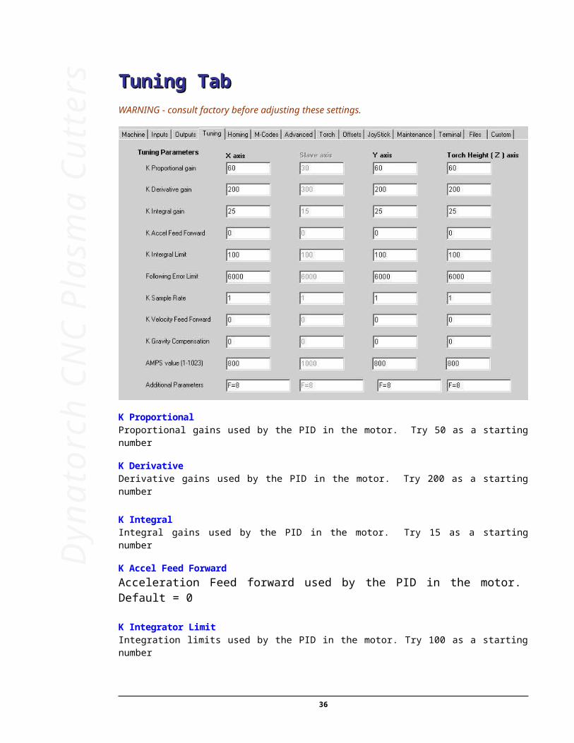
Dyn
ator
ch C
NC
Pla
sma
Cut
ters
Torch TabTorch Tab
Scaled arc voltage inputSome Plasma system can deliver a low (<10volts dc) voltage proportional to the arc voltage… In our standard system, we scale the 0-300 volt arc voltage down to 0-5 volts…. In the case where the plasma supplier can deliver the lower voltage signal, it may not necessarily be 5 volts=300volts, please enter here the voltage that they can supply. One plasma supplier we know uses 0-6 volts for the 0-300 volt reference. In this case you would put 6 in the text box. The default is 5.
Down force used when searching for the plateThis is how much force the motor is allowed to apply while it senses the following error of the encoder, hence sensing that motion has stopped.. Keep this number small, especially for thin material. 80 to 100 is the default. These values represent 8% and 10% of the motors continuous torque rating.
AVC Height sensing delay (0.25 to 2.0 seconds)This is the settling time after the arc has been ignited and movement of the gantry begins, before we allow the AVC to make it’s “height correction”. The initial arc is unstable for the first ½ second or so, and if the AVC was allowed to make corrections it could jump erratically based on the unstable arc. This ¾ second delay, allows the arc to stabilize before we start the correction. Default is 0.75 seconds. If a pierce delay is used, it will be added to this value automatically by the system.
Arc output ON delay in CPU cycles (4069 CPU CYCLES IN ONE SECOND)When cutting VERY this material (0.025”), it is possible that the arc can burn away all the material and extinguish itself before the gantry even starts to move. There is a sequence of events that
36

Dyn
ator
ch C
NC
Pla
sma
Cut
ters
occurs when the arc initiation takes place. First the AVC sends a command to the plasma unit to “turn on the arc”, once the plasma unit determines that the arc is on, it sends a signal to the XY motors saying the arc has been established. It is then that the gantry begins it’s movements, and this exchange of signals can be a small delay in time. During that delay, the thin material can be burnt away completely and the arc goes out. This feature, will delay sending the “turn on the arc” for a short amount of time. This delay can be tuned to have the arc established at the exact time the gantry movement starts it’s move. This feature ONLY works if the “E-Stop on lost Arc” is UN-checked. (this checkbox is located below the arc voltage/arc set- point display). Why is this necessary? It is because we are beginning Gantry movement without arc confirmation; otherwise we would go into an E-Stop condition as soon as we lost the arc. Normally we would not begin movement unless we have confirmation that the arc is established. In this case it is assumed the arc will establish itself and we should just begin movement. This delay allows us to begin movement, which takes some milliseconds, and then turn on the output to ignite the torch. The value here is in CPU cycles of the intelligent motor. This will be a more accurate and more precise value for the delay. The CPU of the motor makes 4069 cycles per second. If you enter a value of 800, it would be 800/4069 = 0.197 seconds. The default value is 1.
AVC Correction Sensitivity FactorThis is the GAIN of the AVC. This factor (a multiplier) sets the correction speed of the AVC. If the value is too low, the AVC will be slow to make corrections, if it is too high, the AVC will overshoot when correcting and become unstable. Typical values are between 10 and 20.
AVC # of Measurements to AverageTypically when you read an analog value, it is best to take several readings and then take the average of those readings. This eliminates spurious noise related measurements that are anomalies that cause erratic jumping of the AVC. Dynatorch has two versions of the electronics that are in the AVC control box. The earlier versions required that we take about 75 measurements and average those prior to making a decision on how much to correct. The current electronics allow us to take 5 to 10 measurements. This gives a much, much faster response time. And this makes a smaller and smoother correction. Basically instead of a 3-4 corrections per second, it can now make 20-25 corrections per second. Because there are those customers with the old electronics out there, the default value is 75, but if you have the new electronics (starting around May 2005), you can use a value between 5 and 15. You should also lower the correction sensitivity if you have the newer electronics.
Fixed distance jogging with the torchThe X and Y-axes can be setup for “fixed” jogging. It is possible to fix the jog amount to 5.0” or even 50.0". Every time you click on X or Y the axis will jog 5.0”…. Well if you have the fixed jog selected and you attempt to jog the Torch 5.0 inches, it’s will crash, since it only has 4” of travel. Rather then prevent the torch from making fixed jogs, we allow you to set the value of a fixed jog for the torch here. So each click of the torch Up/Down button during "Fixed" jogging will more the torch this value. The default is 0.0625” (1/16”)
While cutting, each click of the torch jog button will moveHolding down on the Jog button will cause a buffer underflow in the X and Y motors. By just sending a quick instruction of "Move this amount" to the torch, we eliminate the buffer underflow problem. The default is 0.0625” (1/16”)
Number of seconds to wait for the arc to establish before it is an errorIn previous versions of this program this delay was fixed at 4 seconds, but recently some plasma units are requiring up to 5 or 6 seconds from the time we send the signal to ignite until they actually do. This was causing us to timeout just as the system was igniting. We have now made this value adjustable by the operator. The default is 5 seconds. If, from the time we send the signal to ignite the torch, and we wait 5 seconds without the arc confirmation, we will consider it an error and shut the system down.
37
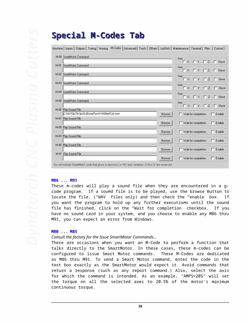
Dyn
ator
ch C
NC
Pla
sma
Cut
ters
Delay time after arc is established and before starting gantry movement, for arc to pierce thick materialThick material, 3/4" to 1.0" may take an extra second or two to pierce thru the material. We will wait this time before beginning the gantry movement to allow the pierce to complete. The default is 0. If you do not want to change the settings for each different part, you can do it is a G-Code program by setting M25 Px.xxx. The P word is used to set the delay time. Be sure to reset this value to 0 when cutting thinner material.
Raise the torch between cuts in OxyFuel modeThis checkbox enables the torch to rise between cuts in the OxyFuel mode. Typically when the system is used with the plasma torch, the torch lowers itself down to touch off on the material, and then it rises up to the pierce height. But with Oxyfuel torch, doing this will most likely extinguish the flame. Therefore we expect the customer to jog the torch down to the preferred cutting height manually, and set the cut height using the button just above the delay timers for preheat and pierce. Once the height has been set, it is memorized for the entire cycle. If this checkbox is not checked, then the torch moves between cuts at wherever it currently is set, it will not raise or lower unless the jog buttons are used by the operator. If this checkbox IS checked, then the torch raises to the home position between cuts. When it arrives at the next cut, it lowers itself back down to the cut height position that was set by the "cut height" pushbutton. The default is checked.
Using Jog buttons during a cycle will re-teach the cutting heightIf you jog the torch up or down during a cut (using the Torch Up/Torch Down buttons) then the memorized cut height position is re-memorized. The current down position that is memorized is displayed in a textbox that shows up next to the set cut height button. This is useful if you need to make a height correction during a cut. The default is checked.
Pause at pierce height before going to cut height for preheatingIn an OxyFuel cycle, the torch will lower itself to the cut height while the preheat and pierce delays time out. However if this box is checked, then it will pause on the way down, at the pierce height above the cut height. The pierce height is the ?/16ths value. This will perform the preheat from the pierce height and then make the pierce at this same height, once the pierce time has expired, the torch will lower itself to the cut height to complete the rest of the cut. This should prevent any splash back that may clog the torch tip if it was to pierce at a lower height.
This output turns ON for OxyFuel Cutting OxygenYou can determine the output you want to turn on the cutting oxygen valve. Default is 2
This output turns ON for OxyFuel Preheat GasYou can determine the output you want to turn on the preheat valve. Default is 4
Leave preheat gas output on between cutsSome systems cannot turn off the preheat between cuts or the torch may extinguish. This will allow the preheat to stay on until the cycle is completed. Default is unchecked
38

Dyn
ator
ch C
NC
Pla
sma
Cut
ters
Offsets TabOffsets Tab
Service and Load PositionsThese locations are based on the homing location of the machine. They are relative to where the machine found home. They are NOT based on the floating zero locations. If you have a 48" x 96" machine, and jogged to the center of the table, then clicked Zero All, even tough the numerical displays will show 0,0, the machine knows where it really is in respect to the home position. So if you click on the Service position, it will do the necessary math required to get the machine to, in the case above, X0 and Y48 based upon where it found home.
0,0 PositionThis location is NOT and I repeat NOT based on the homing location of the machine. It is the position based on the current numerical display values. AND pressing the "0,0 Pos" button DOES NOT require homing! So be careful.
Raise torch first when "Service pos" button is pressedRaise torch first when "Load pos" button is pressedRaise torch first when "0,0 pos" button is pressedThe check boxes will force the torch to raise to it's home position completely, prior to moving the X or Y axes.
G54... G57These dimensions are the offsets from the homing position on the machine. The homing position, also known as the machine reference, is G53, and is relative to the physical home 0,0 location after the machine has done a homing routine. If you would like to work in an offset mode, enter the locations from the machine home here. In the example, if G54 was entered in the G-Code, and a G0 to X0Y0Z0 was performed, the machine would move to x=0.5 y=0.5, z=0.0 but the display (when in program) will show x=0.0, y=0.0, z=0.0. You can choose to jump between the four offset coordinates (G53, G54, G55, G56, G57) at any time. The G54 is your typical program home location. It is offset from the machine home by some distance. In fact, when the machine first finds
39

Dyn
ator
ch C
NC
Pla
sma
Cut
ters
the machine home it then switches to G54 mode. Issuing a G10 will immediately reset the present coordinate (G54 thru G57) to 0,0,0. However, it will not reset the G53, machine home position. Issuing a G92, followed by a X10 or other Axis and position will immediately set the present location to X=10.
WARNING In this program G53 is MODAL.
40

Dyn
ator
ch C
NC
Pla
sma
Cut
ters
Joystick TabJoystick TabTo activate the joystick, go to the Setup pull down window. Go to Machine settings. Go to Joystick Tab. The window you arrive at should look as follows:
Enable the JoystickThis check box is to enable the Joystick; this will be grayed out if Windows does not find any joystick connected to it. When in doubt, go to the Windows Control Panel and look in the Gaming Options for the joystick / game pad devices. From the control panel you can also test and calibrate you joystick.
Reverse X DirThis checkbox will reverse the direction of the motor. If when you push the joystick to the right, and your torch goes to the left, it would be suggested that you change the state of this checkbox.
Reverse Y DirThis checkbox will reverse the direction of the motor. If when you push the joystick to the up, and your torch goes to down, it would be suggested that you change the state of this checkbox.
Use velocity mode for freehand joystick. The freehand joystick is the one on the LEFT The joystick normally operates in torque mode. When the stick is centered it give no torque to the motors, when it is pushed off center, the torque to the motor (corrected for direction) is increased moving the torch. If you are not paying attention and you run the torch to the end stop, and if it is in torque mode, it just applies a force against the end stop, but does not get a following error. Releasing the stick at this point reduces the torque to zero and the motor just sits happily with no torque applied.
41

Dyn
ator
ch C
NC
Pla
sma
Cut
ters
However in Dual Drive Systems, if the axes have any mechanical misalignment, then the master is free to move at will because there is no torque on the motor, but this misalignment can cause the master to move, and this in turn will force the slave to move because it follows every single encoder pulse the master moves, and what happens is the slave, while compensating for misalignment, is pulling the master who is rotating and sending pulses to the slave to follow the master and it is a vicious circle. And the system will walk it way all the way down to the other end of the table. So for these systems, we have this checkbox that puts the motors into velocity mode where they have torque on them all the time on order to maintain position. Bt what can happen here is any move that causes the system to hit something can cause a following error and shut the motors down. So be careful.
Maximum freehand cutting speedThe freehand cutting joystick's speed can be limited. For those who do not want the joystick so sensitive to high-speed moves, they can limit the torque/speed with this slider control.
Joy Stick ButtonsEach button on the joystick is numbered. The function of each numbered button can be found by clicking on the joystick buttons and viewing the indicator that lights up. NO movement will take place while the joystick setup screen is opened.
Joy Stick Button #12Button on the joystick is used to turn on/off an output(s). Select the number with the help of the ? button.
General Joystick Notes:Our cutting system is equipped with a uniquely flexible joystick that allows the user to have almost complete machine control in a portable, hand held device. Normal G-Code cutting operations, jogging (X, Y, and the Torch axis), speed controls, canned and gantry relocations are all available to the user by the joystick use. In addition, the joystick gives the user a freehand (non G-Code) cutting control tool.
The system utilizes a Logitech Dual Action Game Pad (or compatible) as the control device. It is available through us or from most electronic stores, retail outlets. The joystick plugs directly into an available computer USB port. The joystick's working distance from the computer can be extended by employing a standard USB extension cable also locally obtainable. Be sure to install and test the joystick under Windows prior to attempting to use it with the CNC software. This can be done under the game controllers in the control panel of the Windows operating system.
Joystick UseTo activate the joystick click the radio button labeled joystick located under the jogging speed slider control on the main software screen. If it is not visible, then you have not enabled the joystick on the above settings page.
The left joystick controls freehand jogging operation. The further away from center you move the joystick the faster the torch will move. Pressing down on the left joystick while it is off center will result in a doubling of speed (torque).
Table limits are NOT in effect while using the joystick, caution must be observed so as not to run into the X and Y hard stops.
42

Dyn
ator
ch C
NC
Pla
sma
Cut
ters
Straight Line CuttingThe right joystick only is used for straight-line cutting. It operates in a similar manner to the left joystick but only runs at a fixed speed curing a G23 while the torch is down and ignited.
Familiarize yourself with the location of buttons 8 and 6.
If a G-Code file IS presently loaded the joystick cutting operation speed will default to the G- Code initial cut rate modified by the feed rate percentage window. For example: If the G- Code initial rate is set to 120 inches per minute (F120) and the feed rate window percentage is set to 50% the resultant freehand cutting speed will be 60 inches per minute.
If NO G-Code is loaded presently, the cutting speed is defaulted to 100 inches per minute and modified by the feed rate percentage window setting. For example, if the feed rate window is set to 75% the resultant cut speed will be 75 inches per minute.With joystick cutting you must emulate manually the operations done for you automatically by G-Code. For example:
Start cut cycleSend torch in a direction to cut.Stop cut cycle.
To complete a freehand cutting operation do as follows:
1. Position torch over where you wish cut to begin with the left hand joystick.2. Press button number 8 to start cut cycle, this issues a G23 to the controller.3. As soon as the arc is established, move the right joystick in a direction you wish to cut. You can be pushing the joystick before the arc has struck, but it will not move until the arc strikes.4. When reaching the point you wish the cut to stop release the joystick and quickly press button number 6, or just press button 6 and the joystick will stop when the arc goes out.5. The arc will terminate and the torch will retract to it's home position.
Should you run the torch off the edge of the material or into a hole the arc will terminate and an emergency stop will occur. To clear this condition press button number 10. This clears the emergency condition. Then press button number 6 to complete a normal stop cycle.
43

Dyn
ator
ch C
NC
Pla
sma
Cut
ters
Maintenance TabMaintenance Tab
Query Motor InformationThe CNC cutting system has 2 or 3 servomotors connected to it. This tab allows the user to query the motors for some information such as serial and model numbers
Erase Program in Motor(s)The motors have a program in each of them to offload some of the burden from the PC for more efficient control. (They are intelligent motors). There may be an occasion when the factory requests that you clear the program from the motor (like a re-install). If this is the case, you will be instructed to open this page and click the clear the motor program. Once they have been cleared, you must close this program, otherwise expect lots of communication errors as the PC tries to ask the motor to perform an operation for which the motor no longer has the program. When the PC program restarts, it will download fresh programs to each motor and restore everything in it's proper order and be ready to begin work again.
44

Dyn
ator
ch C
NC
Pla
sma
Cut
ters
Terminal TabTerminal Tab
This tab will allow the operator to directly communicate with the motors. It will also give a quick diagnostics of the current condition of the motors. The data in" (E99999)" is the serial number of the motor.
Send toCommands typed into the command line will be sent to either All motors, or a specific motor. You should understand the command structure of the motors before sending instructions. In the example above, "RP" command was sent to all the motors. The Response was the current encoder position of each motor it found. Likewise the command "OFF" would have turned the motors off, "G" turns them back on again, not "ON" as you might assume.
Current motor information
State: Is the motor ON or OFF ?Position: The present encoder position of the motor.Follow Err: the present following error of the motor (it should be 0 or 1)I/O A ... G: the status of the ports A thru G 1 = no input/output active 0= input is active/output is ONBus Volts: The voltage on the pins A1 and A2 of the 7 pin motor connector. (the power supply voltage)Current: The number of amps the motor is currently drawingTemp degrees C: The internal temperature of the motor. These motors shut down automatically at 70 degrees.
45
Dyn
ator
ch C
NC
Pla
sma
Cut
ters
Status: A code that describes the present motor status or error condition. See the motor manual for a complete list.AMPS: The current limitation of the motor. Max current is 1023. If the value is 512 the motor has been limited to 50% of its current draw.Mode: The current mode of the motor.Version: The firmware version of the motor.Analog: The 0-5 volt input from the arc voltage scales from 0 to 1023 unitsSlave Encoder: The current external encoder value of the slave axis
Continuous update and refresh:These control the refresh of the current motor information.
46

Dyn
ator
ch C
NC
Pla
sma
Cut
ters
Files TabFiles Tab
This tab will allow the operator to decide where the files should be opened from and saved to. Clicking on the browse button will allow you to search for the directory (folder) you would like to use.
File Open ExtensionsList the file extension you want to filter when you open a G-Code file. Do not add the "." (dot). Only files with those extension will be filtered through and show up.The defaults are TAP, NC, and TXT. Bt you can add any others you like such as CNC, or whatever your G-Code converter uses as it's extension.
47
Dyn
ator
ch C
NC
Pla
sma
Cut
ters
Custom TabCustom Tab
This tab explains custom M codes that were developed for certain applications. These are typically an instance where the end user wanted a special feature and we added it to the program. If there are special settings pertaining to the custom M code, they can be filled in here.
The Main Cutting Screen The Main Cutting Screen ControlsControlsThis section contains the descriptions of the Main screen elements
The Menu Options The Numeric display The Jogging Buttons The Start Buttons The Go To Position Buttons
Chapter
3
48

Dyn
ator
ch C
NC
Pla
sma
Cut
ters
The Plasma OxyFuel Buttons The Visual Cutting Area
49

Dyn
ator
ch C
NC
Pla
sma
Cut
ters
Menu OptionsMenu Options
Under File:
Open G-Code File
This opens a dialog box for selecting a G-Code file. The file filters are pre-selected by the user on the Advanced Setting page under Machine Settings. The selected file is loaded into the Interpreter. If the immediate folder that opens is not the current program folder, right click on the desktop icon that started the program to check the properties. If there is nothing in the “Starts in:” text area, then add the path to the program folder in the text area.
Edit G-Code and New G-Code (sub) Bank and New Subroutine
These selections open a dialog box for creating a .tap G-Code file, or for editing an existing one. The selected file is loaded into the edit window. The file can be manipulated here and Saved, Saved As, Saved and Opened To save an unaltered version of the file, click the Cancel button.
New G-Code (sub) Code Wizard
This selection opens the code wizard for building simple shapes like circles, rectangles, gussets and bolt circles (even arrays of these)
Save
Choose Save to store the file you are currently working on. It will automatically keep the same file name the file had when opened, and will store to the same location as where the file was residing when opened.
Save As
Use Save As the first time you save a new file, or to save a second copy of a file, giving it a name such as “sunmoon2.tap”. Use Save As to save a copy of the file with the original name to a new location, such as on your desktop or to a zip disk.
Convert DXF - G-Code
This opens the DXF Converter for converting two dimensional .dxf files to G-Code. See DXF Converter for more information.
Exit Program
This will exit and close the program window.
Under Setup:
50

Dyn
ator
ch C
NC
Pla
sma
Cut
ters
Manually Set Home
This will allow the operator to set home manually; it operates the same as if the machine had run its search for home routine. The assumption is that the present location of the axis truly is the home position.
Search for Home
This will home one or all the axes, in the Homing order that was selected in the Homing tab of the machine settings. The homing style, whether Hard Stop or Limit Switch, will depend on the selection made under Machine Settings, on the Inputs and Homing tabs.
Clear homed flags
This removes the "H" or "Axis is homed" bit and sets it to false. This could be useful if the system homed in the wrong palace and now won't allow you to jog back closer to the home switches. By resetting the homed flags, you can jog anywhere because there are no limits when the system is not homed.
Machine Settings
This will open the Machine Settings tab. These settings control and setup the basic machine parameters etc. See the Machine Settings section for complete descriptions.
Under SmartMotor:
This will allow you to go Online and Offline in communicating with the motor. This is the same as the Connect and Disconnect buttons.
Under View:
You must check the Show 2D Path drop down if you want to see the path drawn on the screen while it is cutting. The color and thickness of the path lines are user selectable in the advanced tab of the machine settings.
Under Help:
About
This provides software version and copyright information.
Contents
Opens this Manual. This opens this help file.
51
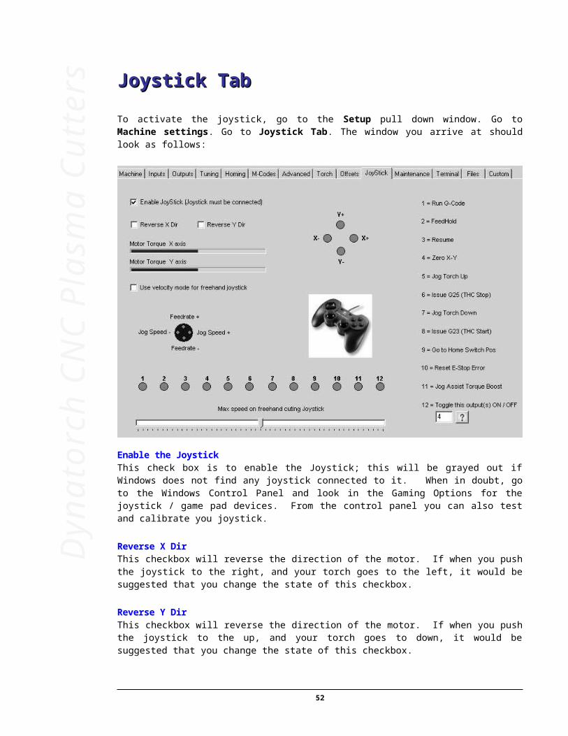
Dyn
ator
ch C
NC
Pla
sma
Cut
ters
The Numeric DisplayThe Numeric Display
Plasma display
Oxyfuel display
ALL ON button
This is a very important button. Whenever the drives turn off due to an error of any kind, the ALL ON button will restore machine operation. This is used after E-stops also. Whenever the drives turn off, the readout numbers will go GRAY to indicate that the drive is off-line. The readouts will still operate and indicate actual machine position even if pushing the machine manually turns the drives. Clicking on the ALL ON will restore the drives to on-line condition and all drive coordinates will return to YELLOW or what ever color you have selected in the advanced settings. See also Axis Label check box below.
Axis label Checkbox (X,Y,Z)
When checked, this will turn the power ON to the Motor and it will servo in position. De- selecting the box will turn the motor OFF, it will be free to turn by hand, but the encoder will maintain the correct position.
Status Error Indicators:
The area below the axes numerical display is the status area. If an error occurs, the error text will turn red, indicating which error occurred. To clear a red error indicator, click on the status area. If the indicator does not clear, the problem still exists. The errors are “OFF” when the motor is off, “POS ERR” when the motor has a following error, “OVER CURR” when an over-current condition has been applied to the motor, and the “TEMP” when the motor is overheated greater than 70 degrees C.
The Master Slave Button (M and S on the button next to the X numeric display)
This button will toggle between the servo position and information of the Master or Slave on the dual drive axis systems. In the above photo, there is NO slave motor so the slave "S" has an X thru it.
Coordinate systems
The numeric display always shows positions in program coordinates, NOT machine coordinates. Because you may wish to re-assign the 0,0 point in order to cut a pattern somewhere out on the table other than the lower left corner, you can re-zero the coordinates anywhere the machine is at any time. The display will not affect the machine limits or rapid positioning buttons at the bottom of the screen.
52

Dyn
ator
ch C
NC
Pla
sma
Cut
ters
The Numerical display also shows the status of the inputs and outputs of ports A thru G on each of the motors.
The round circular indicators are Inputs on Ports B, C, D and G. Inputs cannot be forced on by clicking on them, they are indicators ONLY. Putting the mouse pointer directly over any of the I/O indicators will display the user-defined name of the M-code or assigned input label in the Machine settings.
The rectangular indicators are Outputs on Ports A, E and F (in that order going down on the display). Each output is a user definable M-Codes. These outputs are turned on and off by m-code instructions in your G-Code program, or by moving the mouse over the rectangular indicator and clicking.
53

Dyn
ator
ch C
NC
Pla
sma
Cut
ters
The Jogging WindowThe Jogging Window
X- X+ Y+ Y- Buttons
These buttons allow the individual axes to be jogged. The Jog Speed bar adjusts the speed of the jog. Full speed is approximately one half of the maximum velocity as set in the Machine Settings.
Continuous
If Continuous is selected, the axis will jog continuously while the button is held down, and stop when it is released.
Fixed
If Fixed is selected, each click of the button increments the axis in the amount entered in the fixed text box. Negative numbers are not allowed, jog in the reverse direction if you want to go negative.
Keyboard Jogging
All jogging functions are also available from the keyboard if this check box is selected. The keyboard arrow keys control the X an Y axes
STOP
The Stop Button (with the stop sign) will appear only in the Fixed jogging mode.
Joystick
This radio button will allow the jogging to be controlled by the Joystick. Please see the machine settings for the button usage of the Joystick. We recommend the Logitech game pad available at most department stores for less than $20. We have also tested the Wireless version of the same joystick, and it worked well without the plasma ignited… We have not yet tested the wireless functionality with the plasma ignited (there could be a noise issue). You can cut with the joystick. Windows must detect a joystick attached to the PC for this radio button to appear. For more information, see the Joystick section.
Torch + Torch –
54

Dyn
ator
ch C
NC
Pla
sma
Cut
ters
These buttons allow the torch to be jogged. The Jog Speed bar adjusts the speed of the jog. Similar to the XY jogging arrows, full speed is approximately one half of the maximum velocity as set in the Machine Settings.If Continuous is selected, the axis will jog continuously while the button is held down, and stop when it is released. If it is during a cutting cycle, the torch jog will be limited to the fixed increment that was set on the torch tab of the machine settings.
Fixed torch jogging is also set in the machine settings under the torch tab. Since the torch has only 4" of travel, if you wee to select a 12" move for the X or Y and forget to deselect the fixed button, then the torch would move to where it should never go.
Torch CUT / No-CUT and THC (height control)
THC AND PLASMA THC AND PLASMA
SHOWN ON SHOWN OFF
Just below the Torch up and down jog buttons are two buttons for controlling cut and dry run as well as THC (torch height control for plasma only). If the lightning bolt button is depressed, then the machine will cut when running a G-code program using whichever process (plasma or oxy) was selected above. If the lightning bolt button is not depressed and gray, then no cutting or THC will operate. This includes the initial pierce height sensing operation for plasma. The Lightning Bolt button controls the torch, either plasma or oxyfuel. If the lightning bolt is NOT depressed, neither torch will activate.
If the cut (lighting bolt) button is on, then the THC button will be enabled. This is only operative in Plasma cutting mode. With THC depressed, running a program will cause the torch to find the pierce height, start the arc and cut using arc voltage control. When not depressed the unit will find the pierce height but after cutting begins, no automatic height control will be used. Only the jog buttons will change torch height. The THC button turns on the Automatic Height Control based on the Arc Voltage. This compensates the torch height based on feedback from the arc voltage. The THC button can be turned On and OFF pro grammatically by the M-Codes M26 (on) and M28 (off). For changing it during a cycle.
55

Dyn
ator
ch C
NC
Pla
sma
Cut
ters
Start FunctionsStart Functions
The area below the Jogging Functions on the main screen handles theStart and G-Code Function Buttons
Open Button
This will bring up the File Dialog for selection of a .tap, .nc or .txt file. These file extensions are defaults; file types may be added or deleted under Setup, Machine Settings, Advanced Settings tab. Do not attempt to open another file type, such as a dxf file here. This section is ONLY for G-Codes. Once selected, the G-Code is loaded into the interpreter, and will show up in the main text box. If there are subroutines, they will be in the Subroutine text area, when the program arrives at a gosub (i.e. M98 P100) function call. If the G-Code file you open does not contain an M30 or M02 (either of which are program end statements) an error will occur.
Edit Button
This will a file edit word processor and allow you to change or modify the file you open.
Start Cycle / Step Buttons
Clicking Run G-Code or the Step button will start the sequence. Step processes one line of code at a time, while Start Cycle will read ahead. Stepping thru a g-code is OK for debugging, but not suggested while plasma cutting
Feed Hold Button
This will stop the plasma torch and ramp the speed to zero on all axes thereby stopping any movement
Resume Button
Resume will restart the plasma torch cycle (go down, search for the plate, find pierce height and initiate arc) and then speed back to the designated feed rate.
Reset Button
Clicking Reset while in a FEEDHOLD condition will stop the current execution and reset the file to the first line again. This is the preferred way to halt program execution. If you would like to stop the program, first select Feed Hold. Once the axes have stopped, you can then click Reset G-Code, which will place the system back in manual mode.
56
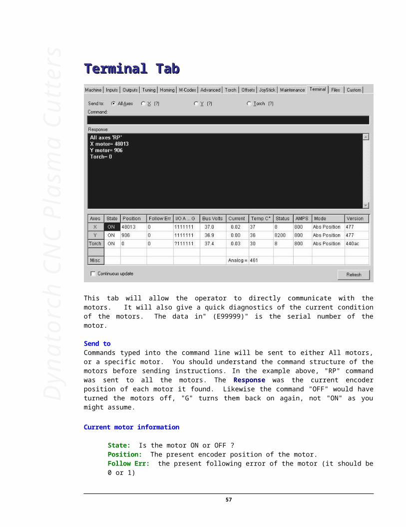
Dyn
ator
ch C
NC
Pla
sma
Cut
ters
Feed rate and Rapid overrides
On the left box is a selection for rapid traverse feed rate. Default is 100%. You may not exceed this speed but you may reduce it as desired by 10% increments to a minimum of 10% using the up/down buttons. On the right is the override for cutting feed rate. Actual feed rate is determined in the program to be run by the “Fx.xx" G-code command. This multiplier will be used against the program feed rate. Minimum is 5% and maximum is 200%. These feed rates can be changed at anytime. If executed during a move, the new feed rate will take effect momentarily. Rapid overrides will takes effect at the next rapid move.
Dis-connect / Connect
Enables the “simulation mode”, which allows you to run through the G-Code program and watch its movement in the display area. No motors will move during this mode. If your path looks correct, it may be safe to begin with your motors moving by selecting Connect to go back Online.
STOP (Space Bar) (hidden under the jogging buttons when not in a cycle)
Clicking this button or pressing the Space Bar shuts off power to all axes. This is the best method to stop movement quickly. Doing this does not lose the axis position, and re-homing is not required. If a motor has been shut OFF, selecting the check box next to the axis label will restore power to the motor, and servo in position. If a red status-indicator located below the numeric display is on, clicking that area will clear the error indicator. If it returns to ON, the error is still present.
Program line number boxesProgram line number boxesLocated just below the feed rate overrides are two boxes showing the program line numbers. The one on the right will always show the last line number where a pierce (actual cut only) occurred. This is a good reference when desiring to go back to the last pierce point. This will be a line with G23 code where the arc was “ON”. A good practice is to return to the G00 line just preceding this line to re-start a cut.
The box on the left shows the active line number to be executed. There are two sets of up/down buttons. The ones on the left of the box increment or decrement by 100 lines. The ones on the
57

Dyn
ator
ch C
NC
Pla
sma
Cut
ters
right of the box increment or decrement by 1 line. You may proceed to a line number and press Start Cycle to start on that line. If the line is a G01 code, the machine will start from where it presently is, cutting immediately if cutting button is on (lightning bolt). If a G02 or G03, unit will proceed to the start of that arc and beginning cutting (if cutting button is on).
Manual data input line (MDI line)Manual data input line (MDI line)
Located in the far lower right of the screen is a blank white box with a green arrow next to it. By clicking in this area, you may manually type in a line of G-code to be executed immediately. All G-code, M code and position commands may be entered one line at a time. This is known as the Manual Data Input (MDI). The MDI allows you to send the immediate G- Code that was typed in the text box. For instance if you wanted to make a rapid move of the Y axis to the 3” location, then Type G0 Y3 in the MDI and either hit enter on the keyboard or click green arrow button, the line will be executed. All coordinates entered are program coordinates, not machine coordinates. .
58
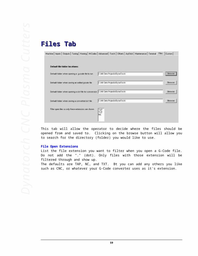
Dyn
ator
ch C
NC
Pla
sma
Cut
ters
User defined / dedicated positions buttonsUser defined / dedicated positions buttons
Located at the bottom of the screen are 5 rapid positioning buttons.
Home Pos button
This button always returns the machine to the lower left location where it found home during the homing procedure. If the machine was not homed, this button will not work.
Load Pos and Service Pos buttons
These are user-defined positions. At installation, these are set to 0,0 or home position. To change these, select Setup->Machine Settings and the Offsets tab. You will be presented with a screen allowing X and Y positions to be assigned to these buttons.
Raise Torch button
This button does a rapid raise to the up position of the torch (Z axis) on machines equipped with a THC or Z-axis lifter station.
0,0 Pos button
This button makes a rapid move to the 0,0 position currently programmed into the machine. This is the floating zero and can be anywhere on the machine. It does NOT require that the machine be homed. So be careful, it will move the axes until the numerical displays read 0,0
Zero X-Y button
This is a very important feature. The X and Y coordinate system may be re-zeroed independently using the “Zero” button at the top next to each axis or X and Y may be re- zeroed together using this button. This re-sets the program zero point for program execution. This does not affect the machine zero or travel limits. This zero is known as the floating zero and can be located anywhere on the machine.
If you wish to cut a part somewhere out on the table, you may jog to a new zero point (lower left corner of where you wish to cut) and then press the Zero X-Y button. This will then move the program to this location for cutting. The machine will retain this as the program zero point until re-set again using the Zero button(s) even if power is lost or the machine is shut off. When the machine re-starts, after homing you may see negative numbers in the coordinate displays. This maintains the program zero relative to the machine travel limits so that you may re-run the program to recover from power outage or other catastrophes and still be exactly where it was before.
A quick re-zero would be by pressing the Home Pos button and then after the machine returns to the lower let corner, press the Zero X-Y button. Program zero and machine zero will now be the same again.
Pressing Zero XY button when a g-code file is opened will cause the ghost image to be redrawn in relationship to the table.
59
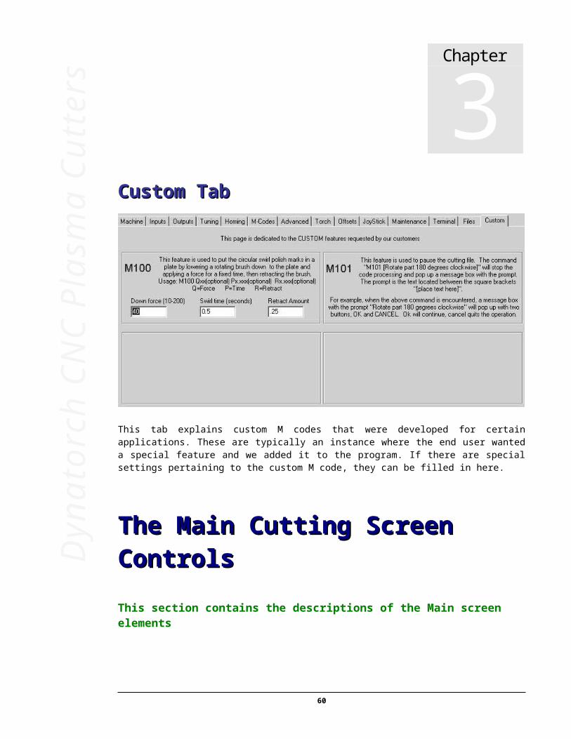
Dyn
ator
ch C
NC
Pla
sma
Cut
ters
E-Stop Assist button
This button handles the E-Stop assistant. Please refer to the E-Stop Assist section of the help file
Zoom All and the Arrow (next to Zoom All) buttons
The Zoom All button shows the complete table with the parts to be cut in relation to where they will be cut. If you drag a box around any object on the main screen and then click the zoom button that appears, then that object will be zoomed in, and fill the screen. While Zoom all is enabled, the table is shown as a blue dotted line on the screen.
You can zoom up to 24 levels, zooming in more and more each time. The Arrow button backs up one zoom level. The Arrow button will be enabled if there is a zoom level you can back up to, otherwise it is disabled.
Zooming while cutting is possible, but it can cause buffer underflows if zoomed or unzoomed during a cut. If you must zoom during a cut, do it during rapid move between cuts or anytime the torch is NOT ignited. Zooming is not recommended while the torch is lit.
60

Dyn
ator
ch C
NC
Pla
sma
Cut
ters
Plasma / Oxyfuel cutting selectionPlasma / Oxyfuel cutting selection
In the far right upper section just above the torch up and down jog buttons is the word Plasma or Oxyfuel. By clicking on this word, you can toggle between cutting methods and parameters.
Plasma Cutting THC functions
If Plasma is selected, you will have the ability to set a pierce height just under the large Torch letters. This has an up and down button next to it incrementing the pierce height by 1/16 + or - and sets the distance that the torch will back up after finding the plate. This may be changed at any time even while cutting and will be reflected on the next pierce operation.
The E-stop on lost arc is normally checked and is only unchecked for cutting very thin material (less than 22 gauge). The V window represents the actual cutting arc voltage at the present time. If not cutting it will show “---”. Next to this is the SP (set point) window. This sets the target cutting voltage and thus the cutting height. The unit will move the torch up or down in order to try to maintain this voltage when cutting. The plasma power supply manual will suggest correct voltages for a given set of consumables, amperages etc. It is best to start high (5 to 10 volts over the recommendation) rather than low to avoid crashing into the plate due to a low voltage set point. You may change this set point at any time even while cutting and the torch will respond by raising or lowering the cut height.
Oxyfuel Cutting functions
If Oxyfuel is selected, you will have the ability to set three (3) timers. The first timer sets the Preheat delay. After the machine reaches the pierce X Y location, the Preheat gas output turns on. The machine stays in position while the output remains on and the preheat delay timer counts down to zero. Then, the cutting oxygen output turns on. The machine still maintains position while the second pierce delay timer marked Pierce counts down to zero. Then the machine begins
61

Dyn
ator
ch C
NC
Pla
sma
Cut
ters
moving along the cut path. At the end of the cut path, both the high preheat and the cutting oxygen are turned off and the machine waits for the Post delay to time out. This post delay allows the pressure in the lines to drop back so that the machine will not still be cutting when the rapid movement to the next pierce point begins.
If the option for Raise Torch Between Cuts is set in the Machine Settings Torch tab, then the cycle will be similar with these added features. First it is expected that the machine operator has jogged the oxy torch down to the height that is preferred for cutting and has clicked the SET CUT HEIGHT button. This teaches the torch the cutting height and allows for the torch to rise to the home position for rapid moves to the next cutting location. Once the cut height has been set, the operator can select the pierce height using the up/down arrows just below the Torch check box, these will increment and decrement the pierce height by 1/16 for each click. With these selection made, the cycle sequence will be as follows: First the torch will rapid to the starting location, it will then lower itself to the cut height PLUS the pierce height. That is, it will stop x/16th's above the cut height and turn on the preheat gas output. It will then wait for the preheat delay to timeout. Once the preheat delay has timed out, it will turn on the cutting oxygen output to pierce thru the material. The pierce delay will start to count down. When the pierce delay expires, the torch will lower itself to the cut height and begin it's XY moves along the path. This ability to remain at the raised pierce height may prevent the blow back from clogging the torch tip when the cutting oxygen first begins to pierce.
Oxyfuel torch types and connections
You may use either a two or three hose torch. A three hose torch is more often used for machine cutting. Using this type of torch, you will have one gas (fuel) line and two Oxygen lines. One for preheat and one for cutting. Three regulators are used. One for the gas (fuel) usually which remains on all the time that the torch is being used and burns at a low flame. The second regulator operates high preheat oxygen sets the flame to a good blue level for heating and the last regulator sets the cutting oxygen pressure. You will need two high flow solenoids for gas service. Generally ASCO brand red-hat series brass solenoids operating on 115VAC. The outputs on the back of the console are pre-configured to deliver 115VAC when on at a maximum of 5 amps each. Mounting these near the torch greatly reduces the bleed- down or post-flow delay time and saves gases. All safety recommendations by the torch manufacturer including safety check valves should be used. Always check for leaks.
Torch CUT / No-CUT and THC (height control)
62

Dyn
ator
ch C
NC
Pla
sma
Cut
ters
THC AND PLASMA THC AND PLASMASHOWN ON SHOWN OFF
Just below the Torch up and down jog buttons are two buttons for controlling cut and dry run as well as THC (torch height control for plasma only). If the lightning bolt button is depressed, then the machine will cut when running a G-code program using whichever process (plasma or oxy) was selected above. If the lightning bolt button is “X”-d out and gray, the no cutting or THC will operate. This includes the initial pierce height sensing operation for plasma.
If the cut (lighting bolt) button is on, then the THC button will be enabled. This is only operative in Plasma cutting mode. With THC depressed, running a program will cause the torch to find the pierce height, start the arc and cut using arc voltage control. Then “X”-d out the unit will find the pierce height but after cutting begins, no automatic height control will be used. Only the jog buttons will change torch height.
63

Dyn
ator
ch C
NC
Pla
sma
Cut
ters
The Visual Cutting AreaThe Visual Cutting AreaThe visual cutting area of the screen shows the work piece path that was represented by the G- Code file currently open.
The dark blue dotted line around the objects represents the limits of you table. If the parts go beyond the dotted line on the screen, then the torch will also attempt to go beyond the table.
When the table is filled with lots of small parts to be cut, then it is hard to actually see what is going on. In this case it is possible to ZOOM up on a particular area of the screen. By left clicking and dragging a box around the object to view, you can zoom up on the object. A button will appear (Zoom) after you have dragged the box around the object, if you click on it the zooming will take place, if you click away from the button, then the zoom is aborted
64

Dyn
ator
ch C
NC
Pla
sma
Cut
ters
Once zoomed up, the Button with the Arrow next to the Zoom All button will be enabled. This is the Un-Zoom button and will take you back one zoom level until you reach the table limits. You can zoom up to 24 levels deep.
Zooming and un-zooming during actual cutting may result in “buffer underflow” errors. If you wish to zoom during a cut, it is suggested you do it when the torch is NOT lit. As an example, when the torch is making a rapid move between objects, or when it is retracting or when it is descending to initialize the arc. Just about anytime other than while the ARC is ignited. This holds especially true when the object is large or the file has a lot of nested parts on the screen. A simple one-piece gusset would not cause a problem. Whereas a 48” square piece of artwork with lots of detail spells trouble. Just use common sense. Also, the speed of the PC and video card have a lot to do with this.
65

Dyn
ator
ch C
NC
Pla
sma
Cut
ters
.
You can continue to zoom beyond 24 levels, but when you click the arrow button to back up, you will immediately back up to level 24 and continue from there backing up.
66

Dyn
ator
ch C
NC
Pla
sma
Cut
ters
The DXF to G-Code ConverterThe DXF to G-Code ConverterThis section contains subjects related to the onboard DXF converter
Main Converter ScreenSetup Menu
Chapter
4
67

Dyn
ator
ch C
NC
Pla
sma
Cut
ters
Creating a G-Code File from a DXF drawingCreating a G-Code File from a DXF drawingThese are the steps needed to transform a raw DXF file into a processed G-Code file ready for cutting using our software.
It is assumed you have completed the settings in the converter setup menu
Click on the Open button, navigate to a file in your operating program directory and locate a sample DXF file. Double left click on this file. This will load the dxf file shaped object into the lower left corner of the white area of the conversion screen. The object image is scaled in size to its relationship with the cutting table as a whole.
Click on the Object button. The object will be magnified to fill the entire white area making it easier to work with.
Click on the Zoom button. Using the left mouse button drag a window around a section of the drawing to magnify it.
Click on the Un-zoom button. This will return the screen to the previous view.
Click on the Start button. The cursor will change to crosshairs. Place the crosshairs over any section of the drawing where you would want the torch to start cutting, this is preferably a lead-in. The segments will begin to be pieced together as they are sorted thru from the list of lines and arcs that make up the drawing. They will turn red indicating they have been joined together as one
68

Dyn
ator
ch C
NC
Pla
sma
Cut
ters
object to be cut. When the path is complete, or at least this section of the file to be cut is complete, you can now...
Move the crosshairs to the next lead-in line. Place the crosshairs over the free end of the lead-in line and left click. This is the next place the torch will lower itself to and begin cutting. As the segments are pieced together they will turn red.
Once all the lines making up the cut path have now been joined and sequenced. Left click on the Test Run button. The program will create a series of red dotted and solid blue lines. The dotted lines indicate rapid moves. The solid blue lines indicate cuts.
If the test run meets your approval click on the Save button. At this point the program will create a G-Code file and save it in the same directory as the DXF file was obtained from.
How it works
Your DXF drawing can be from any cad package that supports the “.dxf” output including: ACAD, Turbo CAD, Fast CAD, AZ CAD, Corel Draw, Photoshop, Paint Shop Pro, and others. The drawing can be made with arcs, fillets, circles, points, lines, and polylines. (no blocks, ellipses or splines) Once the drawing is exported to a .dxf file, it can then be imported to this conversion utility. How does the converter work? Simple... click the start button... then when you click on the screen (the white area) the computer takes the location of where you clicked and starts looking all through the group of lines and arcs that make up the drawing until it finds the closest endpoint to where you clicked. It then gets the other end of that line or arc etc and it then looks thru all the remaining segments for a line or arc that matches that endpoint... this continues until there is no line or arc closer than the join tolerance. At this point it will stop, draw an X on the screen of the next closest endpoint, and display the message " Next closest segment found is x.xx" distance away... Right click to accept it or left click to pick another (lifting Z)" What does that mean. Well if the drawing is poorly drawn, and you intended on a continuous cut to the next point, by right clicking it will automatically insert a connecting line between the two endpoints and continue with the path building. If instead it has reached the end of that particular cut, then you would move the cursor closest to the next begin point and click there to start the next path build. And the torch will do the same thing when it is cutting, it also will stop the cut, raise the torch move to the new location, and begin cutting again. But what if it comes to a place where more than two lines join? How does it know which one to pick? Well, it is based on the current direction of the cut, and it will choose the smoothest path from it's current path. If one path goes off at a 10-degree angle the other goes off at 80 degrees, it will choose the 10-degree angle path.
Saving and Saving SpecialOnce your drawing is converted, you must save the drawing:There are two options: Save and Save Special. Save does exactly what is says, but save special is listed below.
69

Dyn
ator
ch C
NC
Pla
sma
Cut
ters
Scale the object with this ratio xxx to 1This option allows you to scale up or down the size of the converted drawing. Value must be positive (greater than zero).
Save as an Array of Parts
If you want to cut multiple copies of the same drawing, you can do this by building an array. An array, for the purpose of this document, is a layout of one or more copies of the same object, which is organized in columns and rows of identical images, with X = to the number of columns, and Y = the number of rows. Choose the number of rows and columns you want by typing in the number, or by using the left and right arrow keys under the number to adjust it. X multiplied by Y = the total number of images to be cut.
On the left side of this window look for “X (cols) and Y (rows)” area. Here, by changing the numbers, you can define the number of columns and rows in your array.You can also have the system calculate for you the maximum number of parts it can fit into a certain width or height or both.
Our software can create arrays using three methods for spacing the objects in an array.
METHOD ONE:
70

Dyn
ator
ch C
NC
Pla
sma
Cut
ters
When the first radio button is checked an array is created using the starting point of the first object plus an offset distance (both horizontal and vertical0 to define the starting point of the second object. The offset distance is specified in the areas labeled “X axis spacing” and “Y axis spacing”.
METHOD TWO:When the first radio button is checked AND the checkbox directly below it is also checked the object starting point is ignored. The object’s extents are used in place of the starting point. An extent is a theoretical box around an object that is part of the DXF file. The sides of the box correspond to the objects width and height. When using extents the “X axis spacing” and “Y axis spacing: areas will define the horizontal and vertical spacing between the objects (copies) extents boxes.
METHOD THREE:When the lower radio button is checked, arrays are created using an objects starting and ending points. The beginning point of the second object in the array will be co-located with the ending point of the first object. Only one row can be created using this method. It would be rare to use this method.
NOTE: The total material area needed to create your array will appear in the Object Width and Height windows. Once the conversion is completed, it is saved as a .tap file. It is possible to edit the generated code to your liking, if changes are made to the code from the edit command in the main program window (Production Screen).
*Note: this version of our CNC Plasma software only handles 2D drawings.
71

Dyn
ator
ch C
NC
Pla
sma
Cut
ters
DXF Converter Setup MenuDXF Converter Setup MenuThe Settings Tab
Join ToleranceAS the converter is building the cut path, it looks for line ends that touch each other, or are close to each other. This is the tolerance for being close to each other. The default is set at 0.001. The larger the number, the further distance away the system will search for the next line. This is used for poorly drawn objects where the lines do not touch each other.
After conversion, save *.dxf as *.tapThis will automatically save the dxf file you opened as the same name except with a ".tap" extension. This skips the dialog box requesting you to select a name for the file to save as.
Set G92 to initial positionThis check box will issue a G92 command followed by the X and Y value of the first rapid move. The G92 sets the current coordinate system position to the X and Y values. This way when you jog the table to where you want to begin, the code will automatically set it's current position to the correct position. You do not need to push the Zero XY button on the machine.It is for advanced users.
Use these Z commands when Points are encountered in the drawingSometimes points are used in a drawing where you want to pierce a hole, but not traverse the X and Y. Just go down, pierce the hole and go back up. In this case you would issue the G23 for the Z down and a G25 for the Z up. These codes will follow each other immediately, or there may be a G04 Pxx pause to clear the pierce completely. There will be no X Y movement during the pierce.
72

Dyn
ator
ch C
NC
Pla
sma
Cut
ters
The Import Locations Tab
The import location specifies where the drawing will appear on your screen.
Co-Locate with Origin as drawn
The origin is the 0,0 value as defined in the DXF file, superimposed on the table’s 0,0 position.
Locate drawing “Zero” at X.xxx Y.yyy
Specify where you would like the drawing’s zero to be by entering the values for X and Y. “Use Current Position” button changes values to match current gantry position.
Lower Left Extents at X.xxx Y.yyy
This uses the lower left of the extents box (measured by the objects in the drawing file) to position the object at the X&Y location sited in the windows shown.
Use Current Position
This button changes values in the X and Y text boxes to match current gantry position.
73

Dyn
ator
ch C
NC
Pla
sma
Cut
ters
The Conversions (Plasma, OxyFuel, Custom) Tabs
Here you fill in any values in the Plasma /OxyFuel and Custom Conversions Tabs
PreCode
When converting a drawing, and writing the resultant file to the tap file, some codes are required at the very beginning of the file. These codes include things like the feed rate, the coordinate offsets, etc. Anything placed in this text box will be put at the beginning of the file.
PostCode
When converting a drawing, and writing the resultant file to the tap file, some codes are required at the very end of the file. These codes include things like the M30 command which indicate the EOF (end of file) or some sort of code to turn off the exhaust system after a 5 second delay, etc. Anything placed in this text box will be put at the very end of the file.
Z up
This will allow you, for instance, to perform code between each and every path segment. Such as it would be convenient to be able to raise the Z-axis prior to moving from the end of the first segment to the beginning of the second segment (G25). Whenever the path ends, this code is added to the file.
Z Down
This will allow you, for instance, to perform code between each and every path segment. Such as it would be convenient to be able to lower the Z-axis as soon as it gets to the
74

Dyn
ator
ch C
NC
Pla
sma
Cut
ters
beginning of the cut path (after a rapid move). (G23) Whenever the path is about to begin, this code is inserted into the file.
The 4 code boxes can have as much of any G-Code you like entered in them; they are automatically saved when this window closes. There are 3 different sets of Pre/Post and Z up/down commands. One for Plasma cutting, one for OxyFuel cutting and still another for your own custom application.
Typically when using the built in torch height controller, it is advisable to put “G23” in the Z down and “G25” in the Z up code windows. G23 sends the Torch down and strikes the arc, G25 raise the torch. When using the OxyFuel conversion, the G23 and G25 are not appropriate commands, but the M04 and M05 are the correct command for Oxyfuel.(see G-codes and M-codes for more information on what to put in here)
Modifying an Existing G-CodeModifying an Existing G-Code FileFile Our software allows you to change or modify an already existing G-Code.
Scale an objectMove it's originRotate the objectBuild and array of the objects,Convert it to a DXFConvert and existing EIA drawing to our G-Code
Chapter
5
75

Dyn
ator
ch C
NC
Pla
sma
Cut
ters
Modifying a G-CodeModifying a G-CodeOur software allows you to change or modify an already existing G-Code. From the DXF Converter screen, choose the Other menu and select Modify GCode. In this window you can:
1. Scale an object2. Move it's origin3. Rotate the object4. Build and array of the objects,5. Convert it to a DXF6. Convert and existing EIA drawing to our G-Code
Object scaled and it's starting point moved
Browse for a G-Code to Modify
The browse button will allow you to scroll thru the folders and find an existing ".tap" (G-Code file) to open. Once the file has been opened, it should appear as an image in the Original drawing area (bottom left side). If the drawing does not have the X and Y commanded positions on it's first G0, G1, G2or G3 line, it will NOT open the file in the Original window. Rather, it will open the file in the Modified window, which will allow you to modify or fix the problem, you can then save it or click the red arrow button between the text windows to move it from the modified to the original without saving. Once you have a valid file in the original text area, it will show the path image in the Original drawing area. And the Starting XY positions will be filled in on the scale/move tab. This starting XY is the very first position the torch is commanded to go to.
Scaling / Moving
76

Dyn
ator
ch C
NC
Pla
sma
Cut
ters
After a file has been opened, you can now begin to modify it. The first tab is the Scale/Move tab. Here you can increase or decrease the size of the object. You can also move the objects position relative to you table.
Scale Factor
This value can be any POSITIVE number greater than 0. It could be 0.25 to scale it down to 1/4 it's current size or it could be 12 to scale it 12 times bigger than it's original size
Allow scaling of the original XY starting point
This checkbox will scale the starting XY values. If the starting XY is 0,0 then and scale factor is 2, well anything times zero is zero and the starting point will not move. But if the starting point was 3,5 and the scale factor was 0.50, then the new starting point would be 1.5,2.5 which will move the image on the table down to the left. After selecting the scale factor, clicking Modify will compute the new G-Code and draw the new image in the modified drawing area (bottom right).
Maintain original XY starting location when scaling
This checkbox will NOT scale the starting XY values. If the starting XY is 2,5 then after it is scaled it will remain 2,5.
Move starting XY location to X.xxx Y.yyy
This checkbox will first move the starting XY location to this value and then perform any scaling operation while maintaining this value as the starting XY location. If the original XY was found at 2,5 and you wanted it at 10,10... then scaling it with a scale factor of 1.00, will do nothing more than move the origin of the drawing so that the XY Starting point is at 10,10. And if you had a scale factor of 3.0, then the part would be 3 times larger, but with a starting XY location of 10,10.
Measuring the amount of material needed to cut this newly scaled shape
By dragging a Windows rubber band (left click and hold while dragging the mouse) immediately around any of the drawn images, the size of the image will appear above the respective image box.
77

Dyn
ator
ch C
NC
Pla
sma
Cut
ters
Saving As
By clicking the Save as button you can name the re-sized TAP file and save it to a location of your choice
Or you can continue working on the scaled object by...Clicking the Red Arrow button between the text frames will move the modified code to the original code window. This modified code NOW has become your original code. You could scale it again, or you could rotate it, build an array of these parts, and output it to a dxf...
Rotating an object
After a file has been opened, you can now begin to modify it. The rotate allows you to turn the part in any direction. Here you can rotate it forward or backwards. You can rotate the object about many different locations.
Degrees to Rotate
This value can be any POSITIVE or NEGATIVE number between -360.0 to +360.0 degrees. Positive values will rotate the object counter clockwise wand Negative numbers will rotate the object clockwise.
Rotate about...
These check boxes determine the pivot point of rotation. The object's extents are used to calculate the all pivot points other than the starting XY position.
Once you are happy with the rotation, you can continue working on the object by...Clicking the Red Arrow button between the text frames will move the modified code to the original code window. This modified code NOW has become your original code. You could scale it again, move it, build an array of these parts, output it to a dxf...
78

Dyn
ator
ch C
NC
Pla
sma
Cut
ters
Object rotated 90 degrees about it's center
Building an Array
The build array tab allows you to copy the object multiple times in a rectangular pattern. Putting them in columns and rows. The rows can be shifted (staggered) and rotated. Also every other part in a column can be rotated.
Columns
This is the number of object you want placed next to each other, going from left to right on you table.
The E Button
This button will load the width of the extents of the object into the odd and even text boxes to give you a starting point for spacing your array
Odd column spacing
If the column number is odd, this is the centerline distance horizontally between the previous object and this one. The original object on the screen is column 1 row 1, the next column is column 2, and the next one is column 3, 3 is an odd number. It will be begin this amount from the beginning of column 2 (the previous column), and subsequent columns, 5,7,9... will be spaced the same amount away for their previous columns 4,6,8...
79

Dyn
ator
ch C
NC
Pla
sma
Cut
ters
Even column spacing
If the column number is even, this is the centerline distance horizontally between the previous object and this one. The original object on the screen is column 1 row 1, the next column is column 2, 2 is an even number. This object will be begin this amount from the beginning of column 1 (the previous column), and subsequent columns, 4,6,8... will be spaced the same amount away for their previous columns 3,5,7...
Rows
This is the number of object you want placed above to each other, going from bottom to top right on you table.
The E Button
This button will load the height of the extents of the object into the odd and even text boxes to give you a starting point for spacing your array
Odd row spacing
If the row number is odd, this is the centerline distance vertically between the previous object and this one. The original object on the screen is column 1 row 1, the next row is row 2, and the next one is row 3, 3 is an odd number. It will be begin this amount from the beginning of row 2 (the previous row), and subsequent rows, 5,7,9... will be spaced the same amount away for their previous rows 4,6,8...
Even row spacing
If the row number is even, this is the centerline vertically distance between the previous object and this one. The original object on the screen is column 1 row 1, the next row is row 2, 2 is an even number. This object will be begin this amount from the beginning of row 1 (the previous row), and subsequent rows, 4,6,8... will be spaced the same amount away for their previous rows 3,5,7...
Rectangular Array 2 columns by 3 rows
80

Dyn
ator
ch C
NC
Pla
sma
Cut
ters
Special Array Options
These special options allow you to modify the standard rectangular array but shifting and rotating.
Stagger even rows
This will offset the beginning of the even rows by the percentage if the object, this number can be Positive and Negative, shifting the object left or right from it's original starting location. This only affects the even rows
Reduce even rows by 1
Sometimes when the objects are shifted, then last object may fall off the plate. This option allows you to remove the last object from that row.
Rotate object in even numbered rows
This allows you to rotate all the objects placed in the even numbered rows. This is the beginning of a simple nesting. Some experimentation is needed here with the even and odd spacing to get the best nesting
4 columns - 2 rows - shifted 5% - rotated even columns 180 degrees
81

Dyn
ator
ch C
NC
Pla
sma
Cut
ters
Rotate every other object in each rows
This allows you to rotate the even object in each and every row. This is the beginning of a simple nesting. Some experimentation is needed here with the even and odd spacing to get the best nesting
2 rows - 3 columns - rotated every other even object in all rows
Convert a G-Code file to DXF file
This option converts the lines and arcs of the G-Code file to a DXF file. This file should be compatible with most all CAD programs as it is very generic. To convert a file, browse to open it, click Modify and then click save as once the Modified text has stopped writing the file code.
82

Dyn
ator
ch C
NC
Pla
sma
Cut
ters
Include rapid (G0) moves as lines in the output file
Typically rapid moves are NOT in any DXF file as they are solely used by the machine for moves to the next cutting location. But we give you the option to save then if you wish.
Convert an EIA file to G-Code file
One customer had a bunch of these files, he said they were from an old Burny machine. They were written using Absolute dimensions for the I and J arc center values. And the Start cut and stop cut were not the G23 and G25 that we use. We wrote this converter to allow these files to be used with our system.
Once it has been converted, you can continue working on the object by...
83

Dyn
ator
ch C
NC
Pla
sma
Cut
ters
Clicking the Red Arrow button between the text frames will move the modified code to the original code window. This modified code NOW has become your original code. You could scale it again, or you could rotate it, build an array of these parts, and output it to a dxf...
The Code WizardThe Code WizardSo you want to build a simple gusset, a washer, or a flange with 4 boltholes in the corners?
Simple shapes without CAD
Chapter
6
84

Dyn
ator
ch C
NC
Pla
sma
Cut
ters
Code WizardCode Wizard
Brief Overview The code wizard gives you the ability to create simple shapes without drawing them in CAD and saving as a DXF file. By right clicking on the Edit button or clicking on File-New G code - Code Wizard you will be presented with a box that creates G code from shape dimension parameters. Select the type of cutting as Plasma or Oxyfuel. Then select the part type to the right. Select preferences and dimensions. When ready, click on the Build G code button. Now either copy to clipboard or save the G code as a file. The program is now complete and ready to be cut. Arrays of these simple shapes may also be created.
In DepthPlasma or OxyFuel
Checking Plasma will use the Pre, Post, Zup and ZDown codes that you have entered into Setup Screen of the DXF Converter under the Plasma conversion tab. Likewise checking OxyFuel will use the same from the OxyFuel conversion tab. If these conversion tabs are empty, then each time the torch is supposed to raise or lower to go to the next work piece, the code will be missing and thus make the G-Code output incomplete.
Circle, Rectangle, Gusset, or Donut
This is the basic selection of the type of simple part you would like to build. Though there are only 4 listed, by taking them one step at a time, you can build more complex shapes. For instance, if you wanted to build a rounded square flange with a 4-bolt hole pattern in the
85

Dyn
ator
ch C
NC
Pla
sma
Cut
ters
corners and a larger hole in the center, all this can be done. First you would build a circle, then build a circular array of 4 smaller holes, that start at 45 degree angle, then you would build a rectangle of sufficient size as to encompass the big hole and 4 corner holes. Each time you clicked Build, it would have asked you if you want to overwrite the existing code, or add it to the current code. You would always ask to add it to the current code.
When you are finished and click Save it will add the Post code from the proper conversion type and write the program to a file name you select. It is now ready to run, or you can go to Modify G-Code and build an array of these parts.
Clockwise or Counter Clockwise
Some cuts, whether they are holes or circles, (with a hole being the center is thrown away and the outside is used), are cut in a certain direction, either clockwise or counter- clockwise. You can choose here which direction (path) you would like the torch to make as it moves around the part. When cutting a donut, it is already assumed that you want to throw away the center piece, so the center cut is a hole, while the outside cut is a circle. And this direction of cut has been pre-chosen based on typical plasma cutting conventions, CCW for a hole, CW for a circle.
Include a Lead-in or Do Not include a Lead-in
You can choose to have a lead-in or not. It is probably preferred to have some sort of lead-in when cutting, as the initial pierce is usually not very clean. The lead-in will be added to the scrap side (the piece thrown away) and lead into the cut path with a small arc, tangent to the cut path for a smooth transition. The lead-in is usually a 1/4" radius unless the part to be cut is smaller than that, then it is 1/2 the size if the part.
Fillets in the Corners UR (upper right) LL (lower left)...
When cutting rectangular and gusset parts, you can choose to add a radius to any 90 degree corner. This radius can be in inside radius or outside radius. We know that when making gussets, it is helpful to have a bite taken out of the 90-degree corner so the gusset will not interfere with other welds in that area. Likewise, square flanges look better with rounded corners.
Making an Circles or Donuts
86

Dyn
ator
ch C
NC
Pla
sma
Cut
ters
Hole Center X
Enter the X-axis dimension where you would like the center of this hole to be located
Hole Center Y
Enter the Y-axis dimension where you would like the center of this hole to be located
Feed Rate
Enter Feed rate for how fast the torch should move while cut this circle.
Outer Diameter
Enter diameter for this circle. This wizard does not take into account the kerf width. You will need to adjust this dimension, accounting for both kerf width whether it is a hole or a circle, by adding to or subtracting from the diameter.
Making an Gussets
87
Dyn
ator
ch C
NC
Pla
sma
Cut
ters
X Start
Enter the X-axis dimension where you would like the intersection of the 90-degree corner to be located (lower left corner of the gusset)
Y Start
Enter the Y-axis dimension where you would like the intersection of the 90-degree corner to be located (lower left corner of the gusset)
X Leg Length
Enter the length of the bottom leg of the gusset, this is the length of the gusset in the X dimension. Starting from the intersection of the 90-degree corner moving horizontally.
Y Leg Length
Enter the length of the vertical leg of the gusset, this is the length of the gusset in the Y dimension. Starting from the intersection of the 90-degree corner moving vertically.
Feed Rate
Enter Feed rate for how fast the torch should move while cut this gusset.
Fillet radius
If you chose to put a fillet in the 90-degree corner, then enter radius for this corner.
Please remember: This wizard does not take into account the kerf width. You will need to adjust the dimensions, accounting for both kerf width whether it is a cutout or a gusset, by adding to or subtracting from the leg lengths.
88
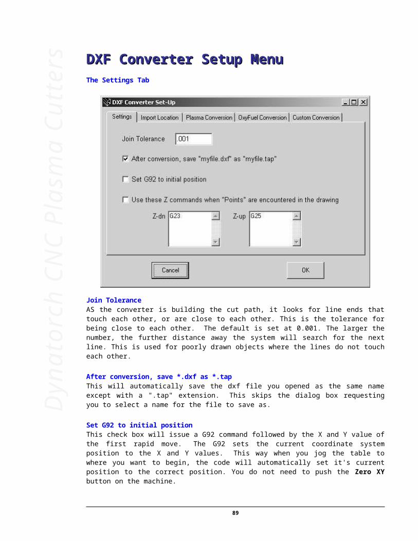
Dyn
ator
ch C
NC
Pla
sma
Cut
ters
Making an Rectangular Shapes
X Start
Enter the X-axis dimension of the lower left corner of the rectangle
Y Start
Enter the Y-axis dimension of the lower left corner of the rectangle
X Width
Enter the width in the X dimension of the rectangle, this is the length of the rectangle in the X dimension. Starting from the lower left corner.
Y Height
Enter the height in the Y dimension of the rectangle, this is the height of the rectangle in the Y dimension. Starting from the lower left corner.
Feed Rate
Enter Feed rate for how fast the torch should move while cut this gusset.
Fillet radii
If you chose to put a fillet in any corner, then enter radius for this corner. This radius is the same for ALL corners. If you would like different radii in the corners, you will have to use your CAD package and draw it accordingly.
Please remember:
89

Dyn
ator
ch C
NC
Pla
sma
Cut
ters
This wizard does not take into account the kerf width. You will need to adjust the dimensions, accounting for both kerf width whether it is a cutout or a rectangle, by adding to or subtracting from the width and height.
Making an ARRAY of Parts
Rectangular
When rectangular is selected, the arrayed parts are arranged in rows and columns. Any simple shape can be put into a rectangular array.
Columns
This is the number of parts to be placed in the X direction, each part placed to the right of the next part.
Rows
This is the number of parts to be placed in the Y direction, each part placed above the next part.
X Column Spacing
This is the distance in the X direction, each part is separated from the previous part. It is NOT the distance from the end of one part to the beginning of the next, rather it is the centerline distance between parts.
Y Row Spacing
This is the distance in the Y direction, each part is separated from the previous part. It is NOT the distance from the top of one part to the bottom of the next, rather it is the centerline distance between parts in the vertical direction.
90

Dyn
ator
ch C
NC
Pla
sma
Cut
ters
Circular
When circular is selected, the arrayed parts are arranged in a bolt hole pattern. Circular arrays only work with round parts, rectangles and gussets cannot be in a circular array.
Bolt Circle Diameter
This is the diameter of the bolt hole circle. The center of each arrayed part will be located on this circle.
Starting Angle Hole #1
This is the angle on the bolt hole circle where the first hole is to be located. Depending upon how the holes are rotated, CW or CCW, the next hole will be located some angular spacing away from this hole.
# of Holes
This is the quantity of holes placed on the bolt circle. If you chose the first hole at 60 degrees, and the number of holes at 2, then if the angular spacing was 45 degrees, then the next hole would be located at 105 degrees on the bolt circle.
Angular Spacing
Angular spacing can be any value, but will be grayed out and pre-calculated if the equal spacing checkbox is checked. This is the distance between each hole from the Starting hole angle.
Equal Spacing
Equal spacing if checked will divide 360 degrees by the number of holes and place the value in the Angular Spacing text area.
Counter Clockwise
When checked this will locate the holes starting from the first hole, to the left (CCW) from the starting hole location. Unchecked will locate the holes to the right, (CW). The compass indicator will show the angular direction, because depending on CW or CCW, the starting angle could be located in a different quadrant.
91

Dyn
ator
ch C
NC
Pla
sma
Cut
ters
E-Stop AssistanceE-Stop AssistanceThe system has stopped.... oh NO !
Right in the middle of a very large cut the torch went out...
What am I going to do !
Chapter
7
92

Dyn
ator
ch C
NC
Pla
sma
Cut
ters
E-Stop AssistantE-Stop Assistant
The E-Stop Assistant is a control function that will allow you to back up in a program. This is allowed only after an E-Stop has occurred. An E-Stop can occur for several reasons, with the main reason being loosing the arc. If you loose the arc during a cut, the system will sense the lost arc and E-Stop all the motors. The system will also E-Stop if the operator hits the E-Stop button or Space Bar during a cycle. Other causes of E-Stops are servo motor failures, such a communications errors, excessive torque overload or excessive overheating. When and if an E-Stop occurs, you can get back to exactly where it E-Stop occurred very easily, and even backtrack thru the program to all the way to the previous pierce point.
When you have the E-Stop condition, all the drives will be turned off, and the outputs will also turn off. Here are the steps needed to get back cutting again:
Click the All On button in the upper left corner of the main screen. At this point is time it is safe for you to raise the torch if needed with the jog buttons Go to the bottom of the screen and click on the E-Stop Assist button The following Window will appear:
You may now click the Move to material load position or Move to torch service position for servicing the torch. During the move to these positions, they can be stopped using the Stop All Motion button. Once you have finished servicing the torch (if it was needed), you can now click on the Move to where E-Stop occurred button. This will return the torch to the location it was when the system trigger a stop due to the E-Stop. From this location, you can now Back up thru the current cut path with the Rev button. The Fwd button at this time will not work because the cycle only saved in it's memory, those positions it has already commanded to the motors. As you click the Rev button, you will see the motors X and Y, move backwards thru the code along the cut path. If you brought it back too far, you can click the Fwd button all the way up to the point where the E-Stop occurred but not beyond. When it has gone back to where you want to restart the program you can now click on the Initialize g-code to restart from this position button. This will find the correct line in the g-code and initialize the axes so they are ready to begin, even from in the middle of an arc. Next click the Close button and you are now
93

Dyn
ator
ch C
NC
Pla
sma
Cut
ters
ready to click the Start Cycle button on the screen to begin the cycle. This will start with a new attempt to pierce and then continue on.
Joystick Cutting and ControlsJoystick Cutting and ControlsOur cutting system is equipped with a uniquely flexible joystick that allows the user to have almost complete machine control in a portable, hand held device. Normal G-Code cutting operations, jogging (X, Y, and the Torch axis), speed controls, canned and gantry relocations are all available to the user by the joystick use. In addition, the joystick gives the user a freehand (non G-Code) cutting control tool.
The system utilizes a Logitech Dual Action Game Pad (or compatible) as the control device. It is available through us or from most electronic stores, retail outlets. The joystick plugs directly into an available computer USB port. The joystick's working distance from the computer can be extended by employing a standard USB extension cable also locally obtainable. (or wireless Joysticks are now available, but you may experience noise issues from the plasma unit when it is cutting)
First install and test the joystick under Windows prior to attempting to use it with the CNC software. This can be done under the game controllers in the control panel of the Windows operating system.
Joy Stick Operations
Chapter
8
94

Dyn
ator
ch C
NC
Pla
sma
Cut
ters
Joystick OperationJoystick OperationTo activate the joystick, go to the Setup pull down window. Go to Machine settings. Go to Joystick Tab. The window you arrive at should look as follows:
Enable the Joystick
This check box is to enable the Joy Stick, this will be grayed out if Windows does not find any joystick connected to it. When in doubt, go to the Windows Control Panel and look in the Gaming Options for the joystick / game pad devices. From the control panel you can also test and calibrate you joystick.
Reverse X Dir
This checkbox will reverse the direction of the motor. If when you push the joystick to the right, and your torch goes to the left, it would be suggested that you change the state of this checkbox.
Reverse Y Dir
This checkbox will reverse the direction of the motor. If when you push the joystick to the up, and your torch goes to down, it would be suggested that you change the state of this checkbox.
Use velocity mode for freehand joystick
95

Dyn
ator
ch C
NC
Pla
sma
Cut
ters
The freehand joystick is the one on the LEFT The joystick normally operates in torque mode. When the stick is centered it give no torque to the motors, when is pushed off center, the torque to the motor (corrected for direction) is increased moving the torch. If you are not paying attention and you run the torch to the end stop, and if it is in torque mode, it just applies a force against the end stop, but does not get a following error. Releasing the stick at this point reduces the torque to zero and the motor just sits happily with no torque applied.
However in Dual Drive Systems, if the axes have any mechanical misalignment, then the master is free to move at will because there is no torque on the motor, but this misalignment can cause the master to move, and this in turn will force the slave to move because it follows every single encoder pulse the master moves, and what happens is the slave, while compensating for misalignment, is pulling the master who is rotating and sending pulses to the slave to follow the master and it is a vicious circle. And the system will walk it way all the way down to the other end of the table. So for these systems, we have this checkbox that puts the motors into velocity mode where they have torque on them all the time on order to maintain position. Bt what can happen here is any move that causes the system to hit something can cause a following error and shut the motors down. So be careful.
Maximum freehand cutting speed
The freehand cutting joystick's speed can be limited. For those who do not want the joystick so sensitive to high-speed moves, they can limit the torque/speed with this slider control.
Joy Stick Buttons
Each button on the joystick is numbered. The function of each numbered button can be found by clicking on the joystick buttons and viewing the indicator that lights up. NO movement will take place while the joystick setup screen is opened.
Joy Stick Button #12
Button on the joystick is used to turn on/off an output(s). Select the number with the help of the ? button.
Joystick Use
To activate the joystick click the radio button labeled joystick located under the jogging speed slider control on the main software screen. If it is not visible, then you have not enabled the joystick on the above settings page.
The left joystick controls freehand jogging operation. The further away from center you move the joystick the faster the torch will move. Pressing down on the left joystick while it is off center will result in a doubling of speed (torque).
Table limits are NOT in effect while using the joystick, caution must be observed so as not to run into the X and Y hard stops.
Straight Line Cutting
The right joystick only is used for straight-line cutting. It operates in a similar manner to the left joystick but only runs at a fixed speed curing a G23 while the torch is down and ignited.
96

Dyn
ator
ch C
NC
Pla
sma
Cut
ters
Familiarize yourself with the location of buttons 8 and 6.
If a G-Code file IS presently loaded the joystick cutting operation speed will default to the G- Code initial cut rate modified by the feed rate percentage window. For example: If the G- Code initial rate is set to 120 inches per minute (F120) and the feed rate window percentage is set to 50% the resultant freehand cutting speed will be 60 inches per minute.
If NO G-Code is loaded presently, the cutting speed is defaulted to 100 inches per minute and modified by the feed rate percentage window setting. For example, if the feed rate window is set to 75% the resultant cut speed will be 75 inches per minute.
With joystick cutting you must emulate manually the operations done for you automatically by G-Code. For example:
Start a cut cycleSend torch in a direction to cut.Stop a cut cycle.
To complete a freehand cutting operation do as follows:
1. Position torch over where you wish cut to begin with the left hand joystick.2. Press button number 8 to start cut cycle, this issues a G23 to the controller.3. As soon as the arc is established, move the right joystick in a direction you wish to cut. You can be pushing the joystick before the arc has struck, but it will not move until the arc strikes.4. When reaching the point you wish the cut to stop release the joystick and quickly press button number 6, or just press button 6 and the joystick will stop when the arc goes out.5. The arc will terminate and the torch will retract to it's home position.
Should you run the torch off the edge of the material or into a hole the arc will terminate and an emergency stop will occur. To clear this condition press button number 10. This clears the emergency condition. Then press button number 6 to complete a normal stop cycle.
Implemented G-CodesImplemented G-CodesG0 RapidG1 Straight LineG2 CW ArcG3 CCW Arc
Chapter
9
97
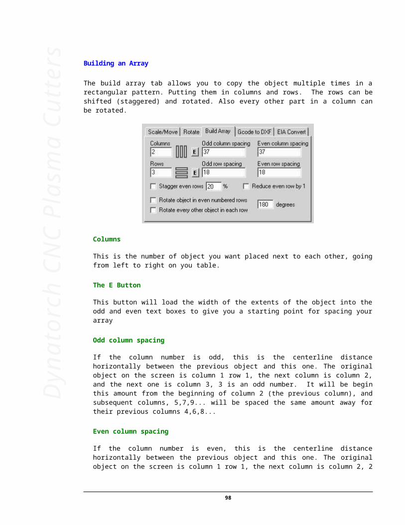
Dyn
ator
ch C
NC
Pla
sma
Cut
ters
G4 PauseG10 Coordinate resetG17 XY PlaneG18 PlaneG19 PlaneG20 InchG21 MetricG23 Start PlasmaG24 Move TorchG25 Stop PlasmaG26 Enable THCG27 Home TorchG28 Disable THCG53 Use Machine CoordinatesG54 - G57 Use Program CoordinatesG76 Repeat G90 AbsoluteG91 RelativeG92 Set Program Coordinates
98

Dyn
ator
ch C
NC
Pla
sma
Cut
ters
G-Codes used in the CNC Plasma CutterG-Codes used in the CNC Plasma CutterG-Code interpreters will operate in different ways. This G-Code interpreter tries to follow most of the standards, but there are a few exceptions and other suggestions to follow. This G-Code interpreter will interpret a number with a decimal point. For example, 1.2345.
G-Codes are normally broken into different groups.group 0 = {g04,g10,g23,g24,g25,g26,g27,g28,g76,g92}group 1 = {g0,g1,g2,g3}group 2 = {g17,g18,g19}group 3 = {g90,g91}group 6 = {g20,g21,g70,g71}group 12 = {g53,g54,g55,g56,g57}
Multiple G-Codes may appear on the same line of G-Code, but only one command from any one group is allowed. The CNC interpreter allows this to some degree, but there may be some ambiguity as to which command is executed first. Therefore, it is far safer and more predictable to use only one G- Code per line. Using one G-Code per line is highly recommended.
Some G-Codes are said to be modal, meaning that once the G-Code is active, additional data can appear without needing to re-state the G-Code on each line. For example, a G0 rapid move is usually followed on the same line by X or Y data. If no other command from the same group appears, additional X and Y data may be entered without an additional G0 code.Again, this programming practice can introduce ambiguity and is highly discouraged. WARNING in this program G53 is MODAL.
M-Codes are usually allowed on the same line as G-Codes. The CNC interpreter allows only one M-Code on a line, which always gets executed after the G- Code. Again, placing multiple codes on one line can introduce ambiguity and is highly discouraged.
Comments are delimited with parentheses () and must appear on a single line. Comments within comments are not allowed (( )). Comments are encouraged, given how unreadable G-Codes tend to be.
The maximum G-Code file size is restricted only by the Windows operating system; if it can give you memory, then it will allow very large file sizes. Some CAM systems, which automatically generate G-Code files, may produce larger files. In these cases, the files can be broken up into multiple files, which are loaded and executed separately. Use of subroutine files is one way for breaking up code. We have run 47 megabyte files successfully.
All G-Code letter characters (G, X, Y, Z, M, F, etc.) must be capitalized and have a space in front of them or appear at the beginning of a line.All programs must end with an M02 or and M30.
G-Codes that are not listed below are ignored by the interpreter.
G00 Rapid Motion
Initiates a rapid, uncoordinated move to the specified X and Y coordinates.Examples:G0 X1.0 Y2.0 (moves to X=1.0, Y=2.0)
99

Dyn
ator
ch C
NC
Pla
sma
Cut
ters
G0 X-0.5 (moves X to -0.5, and Y is unchanged)
G01 Linear Motion
Moves in a coordinated straight line to the specified X and Y coordinates at the specified feed rate. Feed rates are specified in inches, or millimeters, per minute.Example:G01 X1.0 Y2.0 F30.0 (moves in a straight line to X=1.0, Y=2.0 with a feed rate of 30 inches (or mm’s) per minute)
G02 Clockwise Circular Arc
Moves along a clockwise circular arc to the specified X and Y coordinates at the specified feed rate. The center point of the arc is specified using I and J values, which are relative to the starting point of the arc. (The I value is the distance along the X axis and the J value is the distance along the Y axis. R values are not yet supported.) The distance from the starting point to the center point must be the same as the distance from the ending point to the center, or else an error will be generated. The plane in which the arc lies is selected using G-Code G17. To specify a complete circle, the X and Y coordinates can be omitted, or can be set equal to the starting point. The motion will be clockwise with respect to looking down upon the selected plane.Example:(Starting point: X = 1.0, Y = 0.0)G17 F30.0 (select the X-Y plane, set the feed rate to 30 in/min)G2 X0.0 Y-1.0 I-1.0 (creates an 90 degree arc to the point X=0.0, Y=-1.0 with a radius of 1.0, centered about the point X=0, Y=0)
G03 Counterclockwise Circular Arc
Moves along a counterclockwise circular arc to the specified X and Y coordinates at the specified feed rate. The center point of the arc is specified using I and J values, which are relative to the starting point of the arc. (The I value is the distance along the X axis and the J value is the distance along the Y axis. R values are not yet supported.) The distance from the starting point to the center point must be the same as the distance from the ending point to the center, or else an error will be generated. The plane in which the arc lies is selected using G-Code G17. To specify a complete circle, the X and Y coordinates can be omitted, or set equal to the starting point. The motion will be counterclockwise with respect to looking down upon the selected plane.Examples:(Starting point: X = 1.0, Y = 0.0)G17 F30.0 (select the X-Y plane, set the feed rate to 30 in/min)G03 X0.0 Y1.0 I-1.0 (creates an 90 degree arc to the point X=0.0, Y=1.0 with a radius of 1.0, centered about the point X=0, Y=0)
G04 Dwell
Pauses the program for some number of seconds specified with the P parameter. The actual dwell will only be approximately equal to the specified time.Example:G04 P1.5 (pause the program execution for about 1.5 seconds)
G10 Coordinate System Reset
This code "resets" the present coordinate system (G54-G57) to 0,0.You must be in G54 thru G57 for this to function. All axes are set to Zero. If your display was reading X=1.2500 Y=1.0000, the display will read X=0 Y=0 after this G10 is issued. This offset for the G54 thru G57 from machine home is also memorized.
100

Dyn
ator
ch C
NC
Pla
sma
Cut
ters
If you want to reset only one axis, look at the G92 command.Example:If X is 2.354 and Y is 4.555, then after this command:G10 (no other parameters needed)X will be 0.000 and Y will be 0.000
G17 X-Y Plane Selection (This is the normal plane of operation)
Selects the X-Y plane for circular motions. The starting and ending points for circular motions do not have to have the same Z value. In that case, a helical arc will be drawn. Clockwise or counterclockwise will be interpreted as the direction of motion when looking down along the Z-axis.Example:G17 (no other parameters needed)
G18 Z-X Plane Selection (This plane is NOT applicable to the plasma cutter)Selects the Z-X plane for circular motions. The starting and ending points for circular motions must have the same Y value. Clockwise or counterclockwise will be interpreted as the direction of motion when looking down along the Y-axis.Example:G18 (no other parameters needed)
G19 Y-Z Plane Selection (This plane is NOT applicable to the plasma cutter)Selects the Y-Z plane for circular motions. The starting and ending points for circular motions must have the same X value. Clockwise or counterclockwise will be interpreted as the direction of motion when looking down along the X-axis.Example:G19 (no other parameters needed)
G20 and G70 Inch Mode
Inch is the Default operating mode.Example:G20 (no other parameters needed)
G21 and G71 Metric Mode
Pseudo Metric mode takes metric code in, (such as G1 X20) and immediately recalculates the X into inch mode as X.787. The display on the screen will show inches. G20 and G70 are ignored if the user units are set to INCH; likewise G21 and G71 are ignored if the user units are set to METRIC.Example:G21 (no other parameters needed)
G23 Start Plasma Torch Cycle
This command will start the plasma torch moving down to search for the plate. When the plate is found, it stops and retracts to the pierce height. Once it stops at the pierce height, it sends a signal to the Plasma Unit to start the arc. Once the Arc confirmation signal is received by the control, then the XY axes will begin their move.Example:G23 (no other parameters needed)
101

Dyn
ator
ch C
NC
Pla
sma
Cut
ters
G24 Rapid Move of Torch to Commanded Position
This command will send the torch to a commanded position at Rapid speed. If there is a need to position the torch at a known location, without starting the plasma control, then use this command. The Z word is in absolute coordinates. Home is usually 0, and fully down is usually -4.0... valid values are between those limits.Example:G24 Z-2.25 (will send the torch to the –2.25” position)
G25 End Plasma Torch Cycle
This command ends the plasma cycle. When this command is read, the output to the Plasma Unit turns off, extinguishing the Arc. The torch then raises to the top of it’s travel (unless the Z argument is used). Once the torch arrives at the top, it signal the XY motors that it is now OK for them to move. You have the option of changing where the Z-axis goes when it raises. Under standard operation, when only “G25” is issued, the torch raises to the Torch Maximum work area position (typically “0”). If you use the “Z” axis argument, such as G25 Z-1.25, the Z-axis will only raise to the –1.25” position. Issuing an X or Y argument will cause a syntax error. Like the G24, the Z word is in absolute coordinatesExamples:G25 (no other parameters needed)orG25 Z-1.25 (will send the torch to the –1.25” position)
G26 Turn ON the Automatic THC
This command will depress the THC button on the screen. When the button is depressed, it enables the THC height controller based on the arc voltage. When it is not depressed, the THC will remain motionless, and will NOT compensate for the arc voltage changes.Example:G26 (no other parameters needed)
G27 Home Torch (seldom used or needed)
This command will send the torch searching for home position. There is no need to ever use this command, it is left over from older versions.Example:G27 (no other parameters needed)
G28 Turn OFF the Automatic THC
This command will UN-press the THC button on the screen. When the button is NOT depressed, the THC height controller will remain motionless, and will NOT compensate for the arc voltage changes. It's like a HOLD for the Arc Voltage height compensation.Example:G28 (no other parameters needed)
G53 G54 G55 G56 G57 Coordinate offsets
Selects the coordinate offset that you would like to work in. G53 is equal to the machine home position. If you go to X0 Y0 in G53 mode, you will travel to the machine home position. The G54, G55, G56 and G57 modes will offset the machine zero so that when you travel to X0, Y0 in G55 mode, the machine value will be the value set in the G offsets window under the G55X, Y, and Z values, although the interpreter will think it is at machine 0,0.WARNING G53 is MODAL in this program.
102

Dyn
ator
ch C
NC
Pla
sma
Cut
ters
Example:G54 (no other parameters needed)
G76 Repeat a section of the program
This call sets the number of repeat cycles the code will do.This is still under evaluation and most likely will change, but the example would be as follows: Here the system will move rapid from 0,0 to 2,2, then in feed rate from 2,2 to 4,4 and then the program will jump to L1 and it will feed rate to 2,2 then to 4,4 for the Px cycles. Here it is for a total of 5 times (P5). Then it will loop for three times between the L2 and the following G76 P3 command. This is useful if you go to a subroutine after an incremental (G91) move. If no "L" tag is found, it will restart from the beginning of the program.Example:G0 X0 Y0 Z0 (go to home)L1 (tag label for where to restart from)G01 X2 Y2G01 X4 Y4G76 P5 L1 (go back to the location of the L1 label in the program)(move on only after the 5 passes above)L2G91 (switch to incremental move)G1 X1 (increment X over 1 inch)G90 (switch back to absolute move)M98 P111 (Run the O111 subroutine)G76 P3 L2 (go back to the location of the L2 label in the program)(move on only after the 3 passes above)M30 (end of program)
G90 Absolute Mode
Selects using Absolute coordinates in the G commands. This is the standard normal usage.Example:G90 (no other parameters needed)
G91 Relative Mode
Selects using Relative coordinates in the G commands. Any G motion command such as G01 X2 will travel two inches in the positive direction from its present location. Avoid relative moves as it makes reading the G-Code difficult, and it is very possible to forget where you were in the absolute coordinate world.Example:G91 (no other parameters needed)
G92 Set Coordinate System Offset
This Code sets the present coordinate system (G54-G57) to the values set by the X or Y values that follow the command.Example:G54...G92 X2 Y1.5This will make the present location of the coordinate system (G54) equal to X=2.000 and Y=1.500 You must be in G54 thru G57 for this function to work. If you are in G53 mode, it will be ignored. Any or all of the axes can be defined. In other words, "G92 Y2.3" will only set the present position to Y=2.300; all other axes will remain the same.
103

Dyn
ator
ch C
NC
Pla
sma
Cut
ters
Implemented M-CodesImplemented M-CodesM0 Program HaltM01 Program PauseM02 End ProgramM03 and M04 and M05 and M08 and M09M14 Turn ON any single or multiple outputsM15 Turn OFF any single or multiple outputsM21 Continuous Path On M210 Set Maximum Angle Amount M22 Continuous Path Off M23 Slow at Vertex On M24 Slow at Vertex Off M25 Sets the pierce delay timeM26 Enables the THC for automatic arc voltage height sensingM28 Disables the THC for automatic arc voltage height sensingM30 Program End and ResetM41 Turns on an output as soon as motion startsM42 Turns on an output as soon as motion startsM43 Turns on an output as soon as motion startsM45 Turns off output(s) immediatelyM46 Turns off output(s) immediately M47 Turns off output(s) immediately M50 - M57 Waiting for Inputs from the real worldM60 - M73 Outputs to the real worldM80 - M85 Special motor command codes for advanced programmersM86 - M91 Special codes for sound functionsM95 Dwell (exactly the same as an G04)M98 Go To a SubroutineM99 Return from a SubroutineM100 Special Polishing routineM101 Special Pause with optional instructions
Chapter
10
104
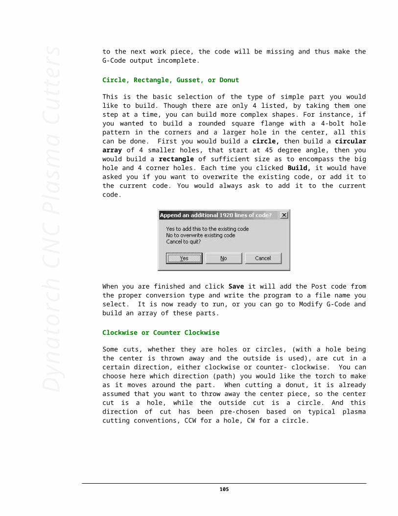
Dyn
ator
ch C
NC
Pla
sma
Cut
ters
M-Codes used in the CNC Plasma CutterM-Codes used in the CNC Plasma Cutter The M-Codes implemented appear below. If an M-Code not listed below is encountered, program execution will stop, and an error message will appear. "Unknown M-Code"
M0 Program Halt
Causes the program halt execution. It acts just like an M02 except it does NOT reset the g-code to the beginning. Execution can be started by clicking the "Start" button.
M01 Program Pause
Causes the program execution to pause. Execution can be resumed by hitting the "OK" button.
M02 End Program (See M30 below)
M03 and M04 and M05 and M08 and M09:
If you are NOT in OxyFuel Mode then: M03 Turns on the selected Motor output. AndM05 Turns M03 selected output OFF
If you ARE in OxyFuel Mode then: M04 Sends the torch down to the cutting height (if the “Raise torch between cuts in OxyFuel mode” is checked). It then turns on the output to operate the valve for the preheat and starts the timer for preheat. Once the preheat has expired, it turns on the output for the cutting oxygen and starts the pierce delay. When the pierce delay expires, the X and Y motors are commanded to move following the path.
M05 Turns M04 OFF, turning off the two valves for cutting oxygen and preheat. If the “Raise torch between cuts in OxyFuel mode” is checked, then the torch will memorize the height where it was when it finished cutting, and retract to the top of it’s travel. This memorized value is used the next time the torch goes down to start a cut.
If you are NOT in OxyFuel Mode then: M08 Turns on the selected Motor output.M09 Turns M08 selected output OFF
M14 Turn ON any single or multiple outputs
This allows the programmer to turn on one or more outputs. This command must be followed with a “P” word. The “P” word is the binary representation of the outputs. The easiest way to figure this is to go to the advanced tab under machine settings and click on any of the “?” marks. This will allow you to select one or more outputs. The number that it calculates is the same number you should use as the P-word. Usage is M14 P7. Turn on XA, XE and XF outputs(Hint XA=1, XE=2. XF=4, YA=8, YE=16…) 1+2+4=7
M15 Turn OFF any single or multiple outputs
See the description for M14… select the Pword for the outputs you would like to turn OFF.Usage is M15 P4. Turn off the XF outputs
105
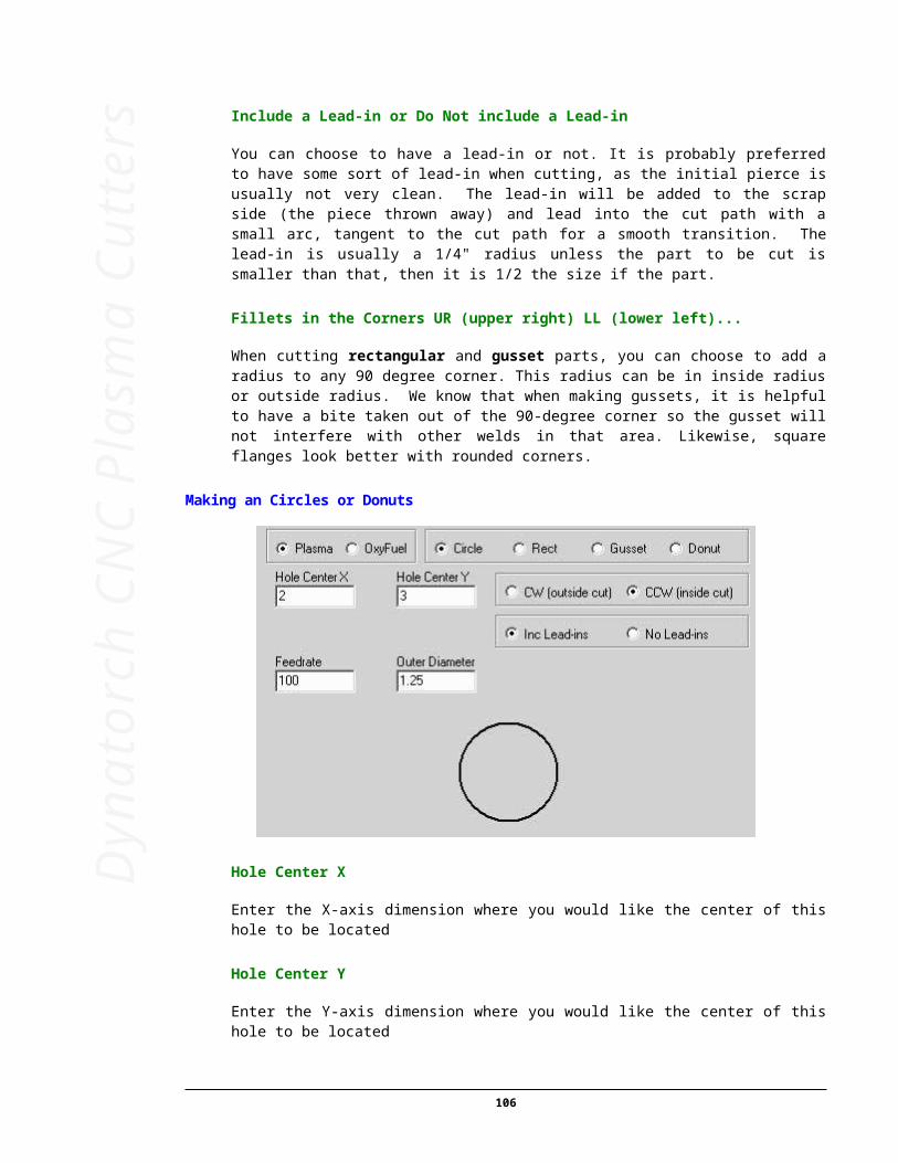
Dyn
ator
ch C
NC
Pla
sma
Cut
ters
M21 Continuous Path On
(VERY seldom used and only by advanced programmers)Turns on the continuous path feature. Path contouring can also be turned on and off via the control panel.
M210 Set Maximum Angle Amount
(VERY seldom used and only by advanced programmers)This sets the maximum angle where it will break the continuous path feature.Usage is M210 P70.Where P is the angle. Max angle can also be set in the machine settings page.
M22 Continuous Path Off
(VERY seldom used and only by advanced programmers)Turns off the continuous path feature. Path contouring can also be turned on and off via the control panel.
M23 Slow at Vertex On
(VERY seldom used and only by advanced programmers)Turns on the slow at vertex feature. Slow at vertex can also be turned on and off via the control panel.
M24 Slow at Vertex Off
(VERY seldom used and only by advanced programmers)Turns off the slow at vertex feature. Slow at vertex can also be turned on and off via the control panel.
M25 Px.xxx Sets the pierce delay time with the P Word.
When you are cutting thick material with the plasma, it is best to have a slight delay to allow the torch to full pierce thru the material prior to starting the XY in motion. This M25 Px.xxx where x.xx is the delay time (i.e. 1.25) When the torch gets the arc confirmation, it will delay this time (1.25 second) and then begin it's path movement.
M26 Enables the THC for automatic arc voltage height sensing
Turns on the THC button on the screen.
M28 Disables the THC for automatic arc voltage height sensing
Turns off the THC button on the screen. This is useful when you know you are about to move to a small hole that will cause the torch to dive if it was under arc voltage height control.
M30 & M02 Program End and Reset
Causes the program execution to halt, and the program will be reset to the beginning. M30 or M02 should appear as the last line of every program. This is an M02, not an M2, you must use the number "0" before the 2, or just use M30. This is only required by the M02, all other M codes, M3,
106
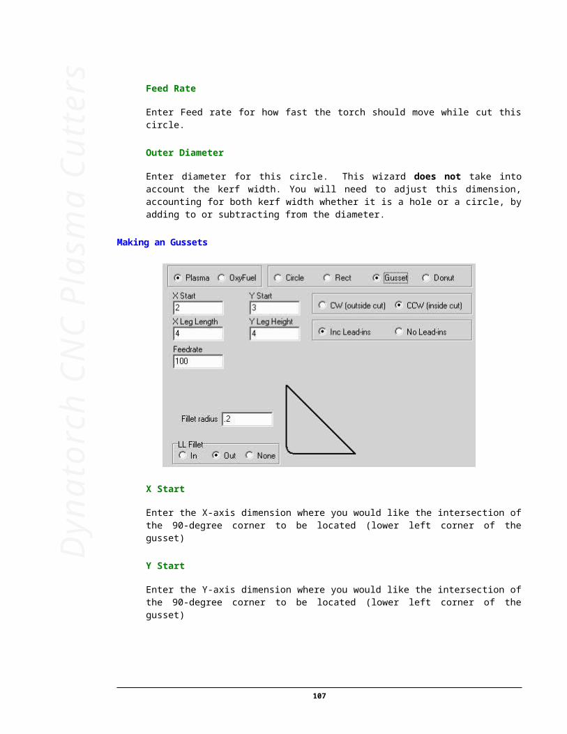
Dyn
ator
ch C
NC
Pla
sma
Cut
ters
M5, M8, M9 do not require the number “0” to be used. M02 ends the program and resets the g-code to the beginning. M30 does the same but it also turns off all outputs that are selected on the advanced tab of the machine settings.Example:M02 (no other parameters needed)M30 (no other parameters needed)
M41 Turns on an output as soon as motion starts...
Sends m=(p-word) GOSUB24 command to the X motorM42 Turns on an output as soon as motion starts...
Sends m=(p-word) GOSUB24 command to the Y motorM43 Turns on an output as soon as motion starts...
Sends m=(p-word) GOSUB24 command to the THC motor
These commands will send the command "m=xxx GOSUB24 " to the selected motor. This subroutine will tell the motor to loop until the in-motion flag is true, at that moment in time, it will turn on one or more outputs. The P word specifies the outputs. The motor has three outputs Ports A, E and F. Port A has a value of 1, port E is 2 and Port F is 4. If you want ports A and F to turn on, the send M41 P5 (P5 is Port A (1) plus Port F (4), 1+4=5). If you just want port E to turn on, then command M41 P2.Example:M42 P7 ( this will turn on all the outputs on the Y motor as soon a motion begins)
M45 Turns off output(s) immediately...
Sends m=(p-word) GOSUB26 command to the X motorM46 Turns off output(s) immediately...
Sends m=(p-word) GOSUB26 command to the Y motorM47 Turns off output(s) immediately...
Sends m=(p-word) GOSUB26 command to the THC motor
These commands will send the command "m=xxx GOSUB26 " to the selected motor. This subroutine will tell the motor to turn off one or more outputs. The P word specifies the outputs. The motor has three outputs Ports A, E and F. Port A has a value of 1, port E is 2 and Port F is 4. If you want ports A and F to turn off, the send M45 P5 (P5 is Port A (1) plus Port F (4), 1+4=5). If you just want port E to turn off, then command M45 P2.Example:M46 P7 (this will turn OFF all the outputs on the Y motor immediately)
M50... M57 Waiting for Inputs from the real world
These commands will cause the program to pause indefinitely waiting for an external input to be true. The inputs are selectable from the Machine Settings Inputs tab. You can set ports "A" or "G" from Axis "X, Y or Z" to "resume on M5x". When these inputs are true, then the system will continue. This could be useful for a Z-axis, which is pneumatically driven. Wait for the signal that the axis is down before resuming motion.
107

Dyn
ator
ch C
NC
Pla
sma
Cut
ters
M60... M73 Outputs to the real world
Turns on/off the user selected Motor outputs. (see the outputs page of the Machine Settings)M60 Pxxx ... M73 Pxxx (with the P word) This will change the "Set Point" value when it turns on the output. Don't know for sure why you would want to do that, but a customer asked for it so we put it in there.
M80... M85 Special codes for advanced programmers, it does special motor command functions
Will either issue a command directly to the Motor such as a gosub or some other SM command. This is an advanced setting and should only be used buy those who are familiar with the motors and their commands. This is a VERY powerful feature, allowing the operator to expand the CNC systems capability to the end of their imagination.
M86... M91 Special codes for sound functions
Will play a sound from the PC sound card. This is useful to sound an alarm prior to Gantry movement or alarm when the cycle is completed.
M95 Dwell (exactly the same as an G04)
Pauses the program for some number of seconds specified with the P parameter. The actual dwell will be approximately equal to the specified time.Example:M95 P1.5 (pause the program execution for about 1.5 seconds)
M98 Go To a Subroutine
M98 P1234 (send the program to the subroutine label 'O1234')The 'P' parameter tells the interpreter which subroutine label to go to. The subroutine label starts with the letter 'O'. To return from a subroutine, end the sub with an M99. (Nested subroutines are not included in this version). The subroutine can be included in the main file, after the M30 or M02, or it can be in a file located in the same folder as the main file, it must have a filename such as "O1234" without any extension. Main files that contain subroutines (after the M30/m02) will have their subroutines extracted and rewritten to the folder as "Oxxxx" during the file open process in the program. Thus, every subroutine now has its own filename and is opened as a file when the call to go to it occurs.
M99 Return from a Subroutine
M99 (returns the interpreter to the next line below the M98 that called it in the main program. The subroutine file must end with M99, not M30.Example:M99 (no other parameters needed)
Sub-Routines in the G CodesSubroutines can be added to the G-Code provided they are not nested. Subroutines must be added after the M30 or M02 of the main program. The subroutine's first line must be the letter 'O' followed by an up to four-digit number. This “Oxxxx” must be by itself on this line, the code should follow immediately on the next line. The subroutine must end with an M99 as the last command on a line all by itself. Calling a subroutine from the main program should be done with an M98 code
108

Dyn
ator
ch C
NC
Pla
sma
Cut
ters
followed by the letter 'P' and the up to four-digit number of the subroutine. If there is a file in the local folder with a filename of "Oxxxx" without extension, it will consider that as the subroutine.Example:G00 X1 Y1M98 P200 (go to sub #200)G00 X2 Y2M98 P300 (go to sub #300)G00 X3 Y3M98 P193 (go to sub #193) *** This will look for a file named "O193"G00 X0 Y0M30 (end of program)
O200 (subroutine label #200)G91G01 X.5 Y.5G90M99 (return to main program)
O300 (subroutine label #300)G17G01 X.5 Y.5G02 J.25M99 (return to main program)*** The program will look in the present folder for a file named "O193" because it does not exist in the main program.
Note: At this time an M98 cannot be placed in a subroutine code block (no nested subroutines.)
M100 Special Polishing routine
M100 This is a special M code that controls the torch vertical slide to allow it to do brush polishing. This command will send the torch down at a fixed down force, once it detects that it hit the plate, it will start a timer for the swirl time, it will the retract a fixed amount and be ready to move to the next location. Q word = down force, P word = swirl time, R word = retract amountExample:M100 Q60 P2.50 R1.0 (Down force = 60, swirl time = 2.5 seconds, retract amount = 1")
M101 Special Pause with optional instructions
M101 This command will pause the g-code command processor with a message for the operator. He will be given a choice of OK to continue and Cancel to quit. OK continues with the gcode, cancel ends the program, (similar to an M30) The message prompt is the text between the brackets "[text goes here]"Example:
109

Dyn
ator
ch C
NC
Pla
sma
Cut
ters
M101 [Please rotate the part 180 degrees]
Wiring HarnessesWiring HarnessesThis section covers the connections of the wiring harness supplied with our drive systems:
Wiring for the Single X axis drive systemWiring for the Dual X axis drive system
Chapter
11
110

Dyn
ator
ch C
NC
Pla
sma
Cut
ters
Single X drive Wiring LayoutSingle X drive Wiring Layout
111

Dyn
ator
ch C
NC
Pla
sma
Cut
ters
Dual X drive Wiring LayoutDual X drive Wiring Layout
112
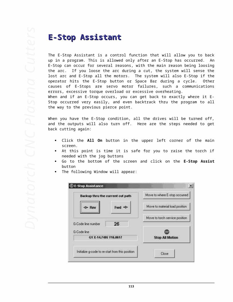
Dyn
ator
ch C
NC
Pla
sma
Cut
ters
GroundingGrounding
Improper grounding is the leading cause of catastrophic failures in the plasma industry.
Do yourself and your wallet a favor.... read and test your system for proper grounds
Is it grounded ?
Chapter
12
113

Dyn
ator
ch C
NC
Pla
sma
Cut
ters
IMPORTANT GROUNDING TESTIMPORTANT GROUNDING TESTVERIFY THIS BEFORE OPERATING THE PLASMA CUTTER
In order to avoid possible damage to electronic components, motors or your PC it is imperative that good grounding be verified prior to operating the plasma generator. Failure to do so will void the warranty and could cause expensive damage to the drive system. Remember that the plasma arc is basically controlled lightening. If your area where you live was prone to frequent lightening strikes, you would want a good lightening rod and surge suppressors connected to every PC or electronic appliance. So with that in mind, please remember there is a computer in each motor, improper grounding could easily allow the plasma arc to act like uncontrolled lightening and destroy any and all electronics and computers in the area. Before you decide against proper grounding, please visit our web site and look at the price of replacement motors.
We suggest you drive a ground rod into the earth within 12 feet of the machine. Ground rods are available from your local home improvement/hardware store (Ace, Lowe’s, Home Depot, etc) Run a large (#6) ground wire from the plasma power leads and the table frame to this ground rod. Also use a ground lead (at least #12) for the 110 circuit that drives the PC and control system to this same ground. See illustration.
Preferred grounding procedure is shown above
All grounding wires should be short in length and larger than 8-awg wires. .
114

Dyn
ator
ch C
NC
Pla
sma
Cut
ters
GROUND TEST PROCEDURE
Connect a 100 W bulb to the ground rod and AC hot. Measure AC voltage with a meter between the ground rod and the AC neutral. Voltage must be below 0.75 VAC. See diagram below
.
A certified, licensed electrician should accomplish the test described. Do not attempt the test yourself as potentially fatal level voltages are involved.
115


