+ All Categories
Home > Documents > Manual de Usuario Reciente - EnDSL-4R5G

Manual de Usuario Reciente - EnDSL-4R5G

Date post: 29-Nov-2015
Category:
Upload: xaviergg
View: 61 times
Download: 2 times
Share this document with a friend
Popular Tags:
125
–© 2010 Encore Electronics, Inc. All rights reserved.COVER © 2010 Encore Electronics, Inc. Product specifications, size, and shape are subject to change without notice, and actual product appearance may differ from that depicted herein. All trademarks and brand names are the properties of their respective holders.
Transcript

–© 2010 Encore Electronics, Inc. All rights reserved.COVER

© 2010 Encore Electronics, Inc.

Product specifications, size, and shape are subject to change without notice, and actual product appearance may differ from that depicted herein.

All trademarks and brand names are the properties of their respective holders.

1www.encore-usa.com

TABLE OF CONTENTS

CHAPTER 1 INTRODUCTION....................................................................... 4

1.1 SAFETY PRECAUTIONS ..................................................................................... 4

1.2 LEDS AND INTERFACES.................................................................................... 5

1.3 FEATURES ........................................................................................................ 6

1.4 APPLICATIONS .................................................................................................. 7

1.5 SPECIFICATIONS ............................................................................................... 7

1.6 SYSTEM REQUIREMENTS................................................................................ 10

1.7 PACKAGE CONTENTS...................................................................................... 10

CHAPTER 2 HARDWARE INSTALLATION .............................................. 11

2.1 CONNECTION WITH NO TELEPHONE SET INSTALLED BEFORE SPLITTER ........... 11

2.2 CONNECTION WITH TELEPHONE SET INSTALLED BEFORE SPLITTER................. 12

CHAPTER 3 SETTING UP THE TCP/IP PROPERTIES............................ 13

3.1 SETTING UP THE TCP/IP PROPERTIES ............................................................. 13

3.1.1 Windows ME/98 .................................................................................... 13

3.1.2 Windows 2000 ....................................................................................... 16

3.1.3 Windows XP .......................................................................................... 19

3.1.4 Windows Vista/7.................................................................................... 22

3.1.5 Linux System.......................................................................................... 25

3.1.6 Mac System............................................................................................ 27

3.2 CHECKING THE TCP/IP CONFIGURATION ....................................................... 28

3.2.1 Windows ME/98 .................................................................................... 28

3.2.2 Windows 2000 ....................................................................................... 29

3.2.3 Windows XP/Vista/7.............................................................................. 30

3.2.4 Linux System.......................................................................................... 31

CHAPTER 4 ACCESS THE WEB CONFIGURATION .............................. 32

2www.encore-usa.com

4.1 HOW TO ACCESS THE ROUTER ....................................................................... 32

4.2 STATUS........................................................................................................... 34

4.2.1 System.................................................................................................... 34

4.2.2 LAN ....................................................................................................... 34

4.2.3 WLAN .................................................................................................... 35

4.2.4 WAN ...................................................................................................... 36

4.2.5 Port Mapping ........................................................................................ 36

4.2.6 Statistics ................................................................................................ 37

4.2.7 ARP Table ............................................................................................. 38

4.3 WIZARD ......................................................................................................... 39

4.3.1 PPPoE................................................................................................... 42

4.3.2 PPPoA................................................................................................... 43

4.3.3 1483 MER: DHCP ................................................................................ 43

4.3.4 1483 MER: Static IP ............................................................................. 45

4.3.5 1483 Bridged......................................................................................... 46

4.3.6 1483 Routed .......................................................................................... 46

4.4 NETWORK ...................................................................................................... 51

4.4.1 LAN ....................................................................................................... 51

4.4.2 WAN ...................................................................................................... 57

4.4.3 WLAN .................................................................................................... 62

4.5 SERVICE ......................................................................................................... 72

4.5.1 DNS ....................................................................................................... 72

4.5.2 Firewall ................................................................................................. 73

4.5.3 UPnP..................................................................................................... 80

4.5.4 IGMP Proxy .......................................................................................... 81

4.5.5 TR069 .................................................................................................... 82

4.5.6 ACL ....................................................................................................... 83

4.6 ADVANCE ....................................................................................................... 86

3www.encore-usa.com

4.6.1 Bridge Setting........................................................................................ 86

4.6.2 Routing .................................................................................................. 87

4.6.3 Port Mapping ........................................................................................ 89

4.6.4 QoS........................................................................................................ 91

4.6.5 SNMP .................................................................................................... 93

4.6.6 Others.................................................................................................... 94

4.7 ADMIN ........................................................................................................... 96

4.7.1 Commit/Reboot...................................................................................... 96

4.7.2 Upgrade................................................................................................. 97

4.7.3 System Log ............................................................................................ 99

4.7.4 Password ............................................................................................... 99

4.7.5 Time Zone............................................................................................ 100

CHAPTER 5 DIAGNOSTIC......................................................................... 102

5.1 PING............................................................................................................. 102

5.2 ATM LOOPBACK .......................................................................................... 102

5.3 ADSL .......................................................................................................... 103

5.4 DIAGNOSTIC TEST........................................................................................ 104

APPENDIX A FREQUENTLY ASKED QUESTIONS.................................. 105

APPENDIX B TROUBLESHOOTING GUIDE ............................................ 109

APPENDIX C GLOSSARY ............................................................................. 113

APPENDIX D REGULATORY NOTES AND STATEMENTS.................... 121

Product specifications, size, and shape are subject to change without notice, and actual

product appearance may differ from that depicted herein.

All trademarks and brand names are the properties of their respective holders.

© 2010 Encore Electronics, Inc. All rights reserved.

4www.encore-usa.com

Chapter 1 Introduction The ENDSL-4R5G Wireless Router / High Speed ADSL 2+ Modem is a highly integrated

wireless Internet gateway device. And, it is fully compliant with ADSL/2/2+, IEEE 802.3/3u and

IEEE 802.11b/g specifications.

It supports one ADSL/2/2+ modem router for high speed ADSL/2/2+ connection to the DSL

telephone line with downstream/upstream data rates up to 24Mbps and 1Mbps for Internet

access, four 10/100Mbps Fast Ethernet ports and one IEEE 802.11g/b 54Mbps wireless Access

Point for connections to PC hosts or other Fast Ethernet or wireless network devices. It is

specially designed for all your possible network connectivity. And, you can share and enjoy

higher quality multimedia and real-time applications such as online gaming, Video-on-Demand

and other bandwidth consuming services. Also the feature-rich routing and NAT functions are

seamlessly integrated to this device for corporation or SOHO users.

The ENDSL-4R5G is the most cost-efficient highly integrated wireless Internet gateway device

you would ever need for all your LAN, wireless and Internet connectivity.

1.1 Safety Precautions

Follow the following instructions to prevent the device from risks and damage caused by fire

or electric power:

Use volume labels to mark the type of power.

Use the power adapter packed within the device package.

Pay attention to the power load of the outlet or prolonged lines. An overburden power

outlet or damaged lines and plugs may cause electric shock or fire accident. Check the

power cords regularly. If you find any damage, replace it at once.

Proper space left for heat dissipation is necessary to avoid damage caused by

overheating to the device. The long and thin holes on the device are designed for heat

dissipation to ensure that the device works normally. Do not cover these heat

dissipation holes.

Do not put this device close to a place where a heat source exits or high temperature

occurs. Avoid the device from direct sunshine.

Do not put this device close to a place where it is over damp or watery. Do not spill any

fluid on this device.

Do not connect this device to any computers or electronic products, unless our

customer engineer or your broadband provider instructs you to do this, because any

wrong connection may cause power or fire risk.

Do not place this device on an unstable surface or support.

5www.encore-usa.com

1.2 LEDs and Interfaces

Front Panel

The following table describes the LEDs of the device:

LEDs Color Status Description

On The initialization of the device is successful. Green

Off The device is powered off.

On The device is self-testing or self-testing is

failed.

Red

Blinks The software is upgrading.

On Connection between the device and the

physical layer of the office is established.

Slow

Blinks No signal is being detected.

Green

Fast

Blinks

The device is handshaking with the physical

layer of the office.

On

The Internet connection is normal in the

routing mode (for example: PPP dial-up is

successful), and no Internet data is being

transmitted.

Blinks Internet data is being transmitted in the routing

mode.

Green

Off The device is in the bridge mode.

Red On

The Internet connection fails after successful

synchronization in the routing mode (for

example: PPP dial-up is failed). On The LAN connection is normal and activated.

Blinks Data is being transmitted in the LAN or Internet

data is being transmitted in the bridge mode. 4/3/2/1 Green

Off The LAN interface is not connected.

On The WLAN connection has been activated.

Blinks Data is being transmitted in the WLAN.

Green

Off The WLAN connection is not activated.

6www.encore-usa.com

LEDs Color Status Description

Blinks WPS is enabled, and is waiting for client to

negotiate.

Green

Off WPS is disabled.

Rear Panel

The following table describes the interfaces of the device:

Interface Description

Wireless antenna.

DSL RJ-11 interface, for connecting to the ADSL interface or a splitter

through a telephone cable.

LAN1/LAN2/

LAN3/LAN4

RJ-45 interface, for connecting to the Ethernet interface of a

computer or the Ethernet devices through an Ethernet cable.

Power Power interface, for connecting to the power adapter of 12 V DC,

800mA.

Reset

Reset to the factory default configuration. Keep the device powered

on, and insert a needle into the hole for 3 seconds, then release it.

The device is reset to the factory default configuration.

WLAN/WPS

Press the button and hold it for 1 second, to enable WLAN.

Press the button and hold it for 1 second and 3 seconds, it does

not take effect.

Press the button and hold it for 3 or more than 3 seconds, to

initialize WPS negotiation.

Power switch, power on or power off the device.

1.3 Features

Compliant to the most updated ADSL2/2+ standards

Support ADSL2+ downstream/upstream data rate up to 24M/1Mbps

IEEE 802.11g WLAN supports up to 54Mbps transmission rate

7www.encore-usa.com

Support WEP, WPA, WPA2 and 802.1X based encryption

Hardware reset button for fast default setting recovery

WLAN/WPS button to enable/disable WLAN or WPS functionalities

Built-in Quick Setup Wizard to easily establish ADSL connection

Web-based management, configuration and firmware upgrade

Embedded firewall (SPI) feature for secure data communication

Support UPnP specification

Support SNTP enactment

Support TR069

1.4 Applications

High speed DSL broadband and Internet access sharing

Audio and video streaming and transferring

PC files and applications sharing

Network and on-line gaming

1.5 Specifications

ADSL

Support ANSI T1.413 Issue 2

Support ITU G.992.1 (G.dmt) Annex A

Support ITU G.992.2 (G.lite) Annex A

Support ITU G.992.3 ADSL2 (G.dmt.bis) Annex A, L, M

Support ITU G.992.4 ADSL2 (G.lite.bis)

Support ITU G.992.5 ADSL2 plus

IEEE 802.3/802.3u ETHERNET/FAST ETHERNET

Compliant with IEEE 802.3/802.3u standards

Support auto-negotiation function

Support IEEE802.3x flow control for full duplex and back pressure flow control

for half duplex

Support MDI/MDI-X auto cross over

IEEE 802.11b/g WIRELESS

IEEE 802.11b/g standards compliant

Frequency band: 2.4 GHz (ISM frequency bands)

8www.encore-usa.com

Data rate:

802.11b compliant: 11, 5.5, 2, 1 Mbps (DSSS/CCK);

802.11g compliant: 54, 48, 36, 24, 18, 12, 9, 6 Mbps (OFDM)

Operating channels: 802.11b/g

11: (Ch. 1-11) – N. America (default)

13: (Ch. 1-13) – Europe ETSI

14: (Ch. 1-14) – Japan

Frequency range: 802.11 b/g

2.412~2.462 GHz – N. America (default)

2.412~2.472 GHz – Europe ETSI

2.412~2.484 GHz – Japan

Transmit output power:

802.11b: 18.5 dBm ± 1.5 dBm

802.11g: 14.5 dBm ±1 .5 dBm

Transmission distance: 300 meters outdoors, 100 meters indoors coverage area

(varying depending on the actual environment.)

Security: 64/128-bit WEP, AES, TKIP, WPA, WPA2, 802.1X

Antenna type: single external detachable antenna

Support WPS features

ATM

Support hardware ATM AAL0, AAL5 and OAM

Support software ATM AAL1 and AAL3/4

Support ATM UBR, CBR, VBR-rt and VBR-nrt traffic shaping QoS

Support up to 8 PVC settings with multiple sessions

Support auto PVC feature

HARDWARE

RTL8671BH ADSL2+ home gateway chipset

16 MB SDRAM

4 MB serial flash ROM

BRIDGING/ROUTING

RFC 2364 PPPoA

RFC 2516 PPPoE

RFC2225/RFC1577 IPoA

RFC 2684/1483 Bridged/Routed/MER

Support transparent bridging (IEEE 802.1D)

Dynamic and static routing (RIP v1/v2)

DHCP server, relay and client

NAT/NAPT with extensive ALG support

Support DNS proxy

9www.encore-usa.com

Support DDNS feature

Support IGMP proxy

Support SNTP

Support port forwarding (virtual server) features

Support DMZ functionality

Support VPN pass-through

MANAGEMENT

Support web-based configuration/management

Support firmware upgrade via HTTP/TFTP

Support built-in diagnostic function of circuitry connect

Support telnet CLI command line

Support hardware reset or web interface reset function

Support configuration files backup and restoration

Support system log, connection status and statistics

Support SNMP v1/v2C (RFC1213 MIB II, RFC 2662 ADSL line MIB, RFC 2515

ATM MIB)

Support SNTP enactment

Support TR069

SECURITY

Support firewall function

Support revised passwords of two-level users

Support electronic signature (preventing different types of versions from

upgrading each other)

Support denial of service (DoS ) which detects and protects against a number of

attacks (such as SYN/FIN/RST Flood, Smurf, WinNuke, Echo Scan, Xmas Tree

Scan)

Packet filter based on IP address and port

Access control based on MAC address

PAP and CHAP authentication

PHYSICAL

Dimension: 165mm (L) X 115mm (W) X 32 mm (H)

Weight : 292 grams

HARDWARE INTERFACE

One 2.4GHz antenna connector

One RJ-11 ADSL port

Four RJ-45 LAN ports

One DC power jack for 12 V DC/800mA power adapter

One reset button for factory default setting recovery

10www.encore-usa.com

One WLAN/WPS button to enable/disable WLAN or WPS functionalities

One push power button

Status LED indicators

ENVIRONMENTAL

Temperature:

Operating: +0 ~ +40oC

Storage: -20 ~ +70 oC

Humidity: (non-condensing)

Operating:10% ~ 90% RH

Storage:5% ~ 90% RH

APPROVALS

FCC Part 15 Class B

CE, EN60950 (LVD) and K.21

UL

RoHS

1.6 System Requirements

Recommended system requirements are as follows:

ADSL Internet service

OS: Windows® 7 / Vista / XP / 2000 / ME / 98SE, Linux® and Mac®

Browser: Internet Explorer® 5.0 or above or equivalent

Network Adapter: 10/100 Ethernet adapter or wireless 802.11b/g adapter

CD-ROM drive

1.7 Package Contents

One ENDSL-4R5G device

One DC power adapter

One splitter (optional)

One QIG (Quick Installation Guide)

One CD-ROM

One RJ-11 cable

One RJ-45 cable

11www.encore-usa.com

Chapter 2 Hardware Installation

Step 1 Connect the DSL interface of the device to the MODEM interface of the splitter

through a telephone cable. Connect the phone to the PHONE interface of the

splitter through a cable. Connect the incoming line to the LINE interface of the

splitter.

The splitter has three interfaces:

LINE: Connect to a wall phone jack (RJ-11 jack).

MODEM: Connect to the ADSL jack of the device.

PHONE: Connect to a telephone set.

Step 2 Connect the LAN interface of the device to the network interface card (NIC) of the

computer through an Ethernet cable (MDI/MDIX).

Note:

Use twisted-pair cables to connect with the hub or switch.

Step 3 Plug one end of the power adapter to the wall outlet and connect the other end to

the Power interface of the device.

2.1 Connection with no telephone set installed before splitter

Figure 1 displays the application diagram for the connection of the router, computer,

splitter and the telephone sets, when no telephone set is placed before the splitter.

Figure 1 Connection diagram (Without connecting telephone set before the splitter)

12www.encore-usa.com

2.2 Connection with telephone set installed before splitter

Figure 2 displays the connection when the splitter is installed close to the router.

Figure 2 Connection diagram (Connecting a telephone set before the splitter)

Note:

When above connection is used, the filter must be installed close to the telephone cable.

See Figure2. Do not use the splitter to replace the filter.

Installing a telephone directly before the splitter may lead to failure of connection between

the device and the central office, or failure of Internet access, or slow connection speed. If

you really need to add a telephone set before the splitter, you must add a micro-filter

before a telephone set. Do not connect several telephones before the splitter or connect

several telephones with the micro-filter.

13www.encore-usa.com

Chapter 3 Setting up the TCP/IP Properties

This chapter describes how to configure the computer to communicate with the router.

Computers access the Internet by using the Transmission Control Protocol/Internet Protocol

(TCP/IP). Each computer in your network must have installed TCP/IP driver, and it has been

selected as its network protocol. If a NIC has already been installed in your computer, then

TCP/IP is already installed as well.

The following description assumes that the router is set to the factory default configuration. The

default LAN IP address of the router is 192.168.1.1. (If the router is not set to the factory default,

keep the device powered on, and insert a needle into the reset hole for 3 seconds, then release

it.)

Note:

Reboot your Windows system might be necessary after setting your computer function as a

DHCP client. In order to properly activate your choice, click OK to reboot your Windows

system.

3.1 Setting up the TCP/IP Properties

You could follow the instructions and configure the NIC installed on your system as a

DHCP client to get the IP address information automatically from the DSL router device.

3.1.1 Windows ME/98

The following describes the operation procedures in Windows ME and Windows 98.

Step 1 Choose Start > Settings > Control Panel. The page as shown in the following

figure appears.

14www.encore-usa.com

Step 2 Double-click the Network icon.

Step 3 In the Network window, click the Configuration tab, and select TCP/IP of the

installed NIC. Then click Properties.

15www.encore-usa.com

Step 4 In the TCP/IP Properties window, click the IP Address tab, and select Obtain an

IP address automatically.

Step 5 In the TCP/IP Properties window, click the Gateway tab. In the window that is

shown, delete all the previous settings.

16www.encore-usa.com

Step 6 In the TCP/IP Properties window, click the DNS Configuration tab, and select

Disable DNS.

Step 7 After setting, click OK.

3.1.2 Windows 2000

The following describes the operation procedures in Windows 2000.

Step 1 Choose Start > Settings > Control Panel. The page as shown in the following

figure appears.

17www.encore-usa.com

Step 2 Double-click the Network and Dial-up Connections icon.

Step 3 Right-click the Local Area Connection icon, and then select Properties in the

menu.

18www.encore-usa.com

Step 4 In the Local Area Connection Properties window, select Internet Protocol

(TCP/IP). Then click Properties.

Step 5 Select Obtain an IP address automatically and Obtain DNS server address

automatically.

Step 6 After setting, click OK.

19www.encore-usa.com

3.1.3 Windows XP

The following describes the operation procedures in Windows XP.

Step 1 Choose Start > Control Panel > Switch to Classic View. The page as shown in

the following figure appears.

Step 2 Double-click the Network Connections icon.

20www.encore-usa.com

Step 3 Right-click the Local Area Connection icon, and then select Properties in the

menu.

Step 4 In the Local Area Connection Properties window, click the General tab, and

select Internet Protocol (TCP/IP). Then click Properties.

21www.encore-usa.com

Step 5 Select Obtain an IP address automatically and Obtain DNS server address

automatically.

Step 6 After setting, click OK.

22www.encore-usa.com

3.1.4 Windows Vista/7

The following describes the operation procedures in Windows Vista/7 systems.

Step 1 Choose Start > Control Panel. The page as shown in the following figure appears.

Step 2 Double-click the Network and Sharing Center icon.

23www.encore-usa.com

Step 3 In the left pane, select Manage network connections, the page as shown in the

following figure appears.

Step 4 Right-click the icon of Local Area Connection, and then select Properties in the

menu.

2

1

24www.encore-usa.com

Step 5 In the Local Area Connection Properties window, select Internet Protocol

Version 4 (TCP/IPV4). Then click Properties.

Step 6 Select Obtain an IP address automatically and Obtain DNS server address

automatically.

Step 7 After setting, click OK.

25www.encore-usa.com

3.1.5 Linux System

The following describes the operation procedures in Ubuntu Linux system.

Step 1 Select Network Connections from Preferences on System menu and the page

as shown in the following figure appears. Then, select the Wired tab.

Step 2 Select Auto eth0 item and click the Edit… button to edit the settings.

26www.encore-usa.com

Step 3 On the Edit Auto eht0 window, check the IPv4 Settings tab.

Step 4 On the IPv4 Settings tab, select Automatic (DHCP) from the Method pull-down

menu.

Step 5 After setting, click Apply button.

27www.encore-usa.com

3.1.6 Mac System

The following describes the operation procedures in Mac OS X Version 10.6.3 system.

Step 1 Choose System Preferences from Dock on the system desktop. The page as

shown in the following figure appears.

Step 2 Double-click the Network icon in the Internet & Wireless section, and you will see

the figure below. Click the Ethernet connected from connections list on left side

and select Using DHCP setting in Configure IPv4 option on the right side. And,

you would be able to see the IP Address assignment in the same window

Step 3 Click Apply button to finish the settings.

28www.encore-usa.com

3.2 Checking the TCP/IP Configuration

After you configure the NIC of the computer and reboot the system, you can check the TCP/IP

configuration by using the following utility that is provided by your Windows system.

3.2.1 Windows ME/98

Step 1 Choose Start > Run.

Step 2 In the Open field, enter command, and then click OK.

Step 3 In the MS-DOS Prompt window, enter Winipcfg, and then press Enter. The page

as shown in the following figure appears. All the Ethernet adapter information is

displayed. You can check the configuration of the computer.

IP Address: 192.168.1.x

Subnet Mask: 255.255.255.0

Default Gateway: 192.168.1.1

29www.encore-usa.com

Step 4 Enter Exit, and press Enter. Then the MS-DOS Prompt window logouts.

3.2.2 Windows 2000

Step 1 Choose Start > Run.

Step 2 In the Open field, enter cmd, and then click OK.

Step 3 In the prompt window, enter ipconfig/all, and then press Enter. The page as

shown in the following figure appears. All the Ethernet adapter information is

displayed. You can check the configuration of the computer.

IP Address: 192.168.1.x

Subnet Mask: 255.255.255.0

Default Gateway: 192.168.1.1

30www.encore-usa.com

Step 4 Enter Exit, and press Enter. Then the prompt window logouts.

3.2.3 Windows XP/Vista/7

Step 1 Choose Start > Run.

Step 2 In the Open field, enter cmd, and then click OK.

Step 3 In the prompt window, enter ipconfig/all, and then press Enter. The page as

shown in the following figure appears. All the Ethernet adapter information is

displayed. You can check the configuration of the computer.

IP Address: 192.168.1.x

Subnet Mask: 255.255.255.0

Default Gateway: 192.168.1.1

Step 4 Enter Exit, and press Enter. Then the prompt window logouts.

31www.encore-usa.com

3.2.4 Linux System

Step 1 Access the command line Terminal window from the Accessories sub-menu

in the Applications menu.

Step 2 Use “ifconfig” command to check the IP address assignment in the command

line Terminal window.

32www.encore-usa.com

Chapter 4 Access the Web Configuration

This chapter describes how to configure the router by using the Web-based configuration

utility.

4.1 How to Access the Router

The following is the detailed description of accessing the router for the first time.

Step 1 Open the Internet Explorer (IE) or other browser software and enter

http://192.168.1.1 in the URL address field.

Step 2 In the Login page that is displayed, enter the user name and password.

The router supports two-level user accounts for accessing.

The user name and password of the super user are admin and admin respectively.

The user name and password of the common user are user and user respectively.

33www.encore-usa.com

If you log in as a super user, the page as shown in the following figure appears. You can check,

configure and modify all the settings.

If you log in as a common user, you can check the status of the router, but can not configure

the most of the settings.

If there is no operation in the Web configuration page within five minutes, the router

automatically logouts. You need to log in again.

Note:

In the Web configuration page, you can click Apply Changes to save the settings

temporarily. If you want to save the settings in this page permanently, click Save of

Attention that appears at the bottom of the Web page after the configuration.

34www.encore-usa.com

4.2 Status

In the navigation bar, click Status. In the Status page that is displayed contains: System,

LAN, WLAN, WAN, Port Mapping, Statistics, and ARP Table.

4.2.1 System

Choose Status > System. The page that is displayed shows the current status and some

basic settings of the router, including uptime, software version, DSP version, upstream speed,

and downstream speed.

4.2.2 LAN

Choose Status > LAN. The page that is displayed shows some basic LAN settings of the

router. In this page, you can view the LAN IP address, DHCP server status, MAC address,

and DHCP client table. If you want to configure the LAN network, refer to Chapter 04.4.1.1

LAN IP.

35www.encore-usa.com

4.2.3 WLAN

Choose Status > WLAN. The page that is displayed shows some basic WLAN settings of the

router. In this page, you can view basic status of wireless LAN (WLAN). If you want to

configure the WAN network, refer to Chapter 00.

36www.encore-usa.com

4.2.4 WAN

Choose Status > WAN. The page that is displayed shows some basic WAN settings of the

router. In this page, you can view basic status of WAN and DNS server. If you want to

configure the WAN network, refer to chapter 4.4.2 WAN.

4.2.5 Port Mapping

Choose Status > Port Mapping. In this page, you can view the mapping relation and the

status of port mapping.

37www.encore-usa.com

4.2.6 Statistics

Choose Status > Statistics. The Statistics page that is displayed contains Traffic

Statistics and ADSL Statistics.

4.2.6.1 Traffic Statistics

Click Traffic Statistics, the page as shown in the following figure appears. In this page,

you can view the statistics of transmitted packets and received packets at each network

interface.

4.2.6.2 ADSL Statistics

Click ADSL Statistics, the page as shown in the following figure appears. In this page, you

can view the ADSL line status, upstream speed, downstream speed, and other information.

38www.encore-usa.com

4.2.7 ARP Table

Choose Status > ARP Table. In this page, you can view MAC addresses of the router and the

connected devices.

39www.encore-usa.com

4.3 Wizard

The Wizard page guides fast and accurate configuration of the Internet connection and other

important parameters. The following sections describe these various configuration parameters.

Whether you configure these parameters or use the default ones, click Next to enable your

Internet connection.

When subscribing to a broadband service, you should be aware of the method by which you are

connected to the Internet. Your physical WAN device can be either PPP, ADSL, or both. The

technical information about the properties of your Internet connection is provided by your

Internet service provider (ISP). For example, your ISP should inform you whether you are

connected to the Internet using a static or dynamic IP address, and the protocol that you use to

communicate on the Internet.

In the navigation bar, click Wizard. The page as shown in the following figure appears.

The following table describes the parameters in this page:

Field Description

User Name Select the user name for accessing the router.

New Password

Enter the password to which you want to change the old

password. The password can not contain space key, %,

“, ? or &.

Confirmed Password Enter the new password again.

40www.encore-usa.com

You are recommended to change the password after login for the first time. Enter the new

password twice and click Next. The page as shown in the following figure appears. In this

page, you can configure the system time and Network Time Protocol (NTP) server.

The following table describes the parameters in this page:

Field Description

State Disable or enable NTP. You need to enable it if you want to configure the

parameters in this page.

Server IP Enter the IP address of the specified time server manually.

Interval Specify the interval that the router synchronizes the time with the server.

Time Zone Select the time zone in which area you are from the drop-down list.

GMT time It displays the Greenwich Mean Time (GMT).

41www.encore-usa.com

After settings done, click Next. The page as shown in the following figure appears.

The procedure for configuring the ADSL settings of the router is as follows:

Step 1 Select the country where you are from the drop-down list.

Step 2 Select the corresponding ISP from the drop-down list.

After the selection, the protocol, connection type, VPI, VCI are displayed.

Step 3 Enter the correction information for dial-up.

There are six protocols available: PPPoE, PPPoA, 1483 MER: DHCP, 1483 MER: Static IP,

1483 Bridged, and 1483 Routed.

For example, please select Singapore and Infoserve Dial-up connection ADSL service from

the corresponding drop-down lists. The page as shown in the following figure appears.

42www.encore-usa.com

]

4.3.1 PPPoE

In this example, select PPPoE as the protocol.

The following table describes the parameters in this page:

Field Description

Protocol There are six protocols available. In this example, PPPoE is the

protocol for dial-up.

Connection

Type

There are two connection types available: VC-Mux and LLC. In

this example, LLC is the connection type.

VPI

Virtual path identifier (VPI) is the virtual path between two points

in an ATM network. Its valid value is in the range of 0 to 255. In

this example, VPI is set to 0.

VCI

Virtual channel identifier (VCI) is the virtual channel between

two points in an ATM network. Its valid value is in the range of

32 to 65535 (0 to 31 is reserved for local management of ATM

traffic). In this example, VCI is set to 100.

User Name Enter the user name for PPPoE dial-up, which is provided by

your ISP.

43www.encore-usa.com

Field Description

Password Enter the password for PPPoE dial-up, which is provided by

your ISP.

Confirmed

Password

Enter the password again.

4.3.2 PPPoA

Select PPPoA as the protocol, the page as shown in the following figure appears.

For the parameters in this page, refer to the parameter description of PPPoE protocol.

4.3.3 1483 MER: DHCP

Select 1483 MER: DHCP as the protocol, the page as shown in the following page appears.

44www.encore-usa.com

After entering correct VPI and VCI, DHCP automatically assigns the WAN IP address, gateway

and DNS information to this device.

45www.encore-usa.com

4.3.4 1483 MER: Static IP

Select 1483 MER: Static IP as the protocol, the page as shown in the following page appears.

The following table describes the parameters in this page:

Field Description

Protocol There are six protocols available. In this example, 1483 MER:

Static IP is the protocol for dial-up.

Connection

Type

There are two connection types available: VC-Mux and LLC. In

this example, LLC is the connection type.

VPI

Virtual path identifier (VPI) is the virtual path between two points

in an ATM network. Its valid value is in the range of 0 to 255. In

this example, VPI is set to 0.

VCI

Virtual channel identifier (VCI) is the virtual channel between

two points in an ATM network. Its valid value is in the range of

32 to 65535 (0 to 31 is reserved for local management of ATM

traffic). In this example, VCI is set to 100.

WAN IP Enter the IP address for WAN connection, which is provided by

46www.encore-usa.com

Field Description

Address your ISP.

Subnet Mask Enter the subnet mask of the WAN IP address, which is

provided by your ISP.

Default

Gateway

Enter the default gateway, which is provided by your ISP.

Primary DNS

Server

Enter the DNS server, which is provided by your ISP.

4.3.5 1483 Bridged

Select 1483 Bridged as the connection type, the page as shown in the following figure

appears.

4.3.6 1483 Routed

Select 1483 Routed as the connection type, the page as shown in the following figure

appears.

47www.encore-usa.com

In this page, you need to enter the IP address of WAN connection, subnet mask, default gateway,

and DNS server which are provided by your ISP.

For parameters in this page, refer to the parameter description of 1483 MER: Static IP.

After setting, click Next, the page as shown in the following page appears.

The following table describes the parameters in this page:

48www.encore-usa.com

Field Description

WLAN

Interface

Enable or disable WLAN.

You need to enable WAN interface only if you want to use

WLAN and configure the parameters in this page.

Band Select the working mode of the router. You can select 802.11b,

802.11g, or Mixed (802.11b/11g).

SSID

The service set identification (SSID) is a unique name to identify

the router in the wireless LAN. Wireless stations associating to

the router must have the same SSID. Enter a descriptive name

that is used when the wireless client connecting to the router. By

default, the SSID is ENDSL-4R5G.

Encryption

Configure the wireless encryption mode. You can choose None,

WEP, WPA (TKIP), WPA (AES), WPA2 (AES), WPA2 (TKIP),

or WPA2 Mixed.

Wired equivalent privacy (WEP) encrypts data frames

before transmitting over the wireless network.

Wi-Fi protected access (WPA) is a subset of the

IEEE802.11i security specification draft.

WPA2 Mixed is the collection of WPA and WPA2 encryption

modes. The wireless client establishes the connection

between the router through WPA or WPA2.

Key differences between WPA and WEP are user authentication

and improved data encryption.

Set the encryption to WEP, the page as shown in the following figure appears.

The following describes the parameters of WEP encryption:

Field Description

Key Length Select the WEP key length. You can select 64-bit or 128-bit.

Key Format

If the key length is set to 64-bit, you can select ASCII (5

characters) or Hex (10 characters).

If the key length is set to 128-bit, you can select ASCII

49www.encore-usa.com

Field Description

(13 characters) or Hex (26 characters).

Key

The encryption key is used to encrypt the data. Both the

router and wireless stations must use the same encryption

key for data transmission.

If you select 64-bit and ASCII (5 characters), enter any

5 ASCII characters.

If you select 64-bit and Hex (10 characters), enter any

10 hexadecimal characters.

If you select 128-bit and ASCII (13 characters), enter

any 13 ASCII characters.

If you select 128-bit and Hex (26 characters), enter

any 26 hexadecimal characters.

Set the encryption to WPA (TKIP), the page as shown in the following figure appears.

The following table describes the parameters of WPA (TKIP) encryption:

Field Description

Enterprise (RADIUS)

If you select it, you need to enter the port, IP address, and

password of the Radius server. You need to enter the user

name and password provided by the Radius server when

the wireless client connects the router.

Personal

(Pre-Shared Key)

If you select it, you need to enter the pre-shared key in the

Pre-Shared Key field.

For the parameters of WPA (AES), WPA2 (TKIP), WPA2 (AES), and WPA2 Mixed refer to the

parameter description of WPA (TKIP).

50www.encore-usa.com

After finishing the configuration, click Next. The page as shown in the following figure appears.

Click Back to modify the settings.

Click Finish to take the settings into effect temporarily.

Click Reset to cancel the settings.

51www.encore-usa.com

4.4 Network

In the navigation bar, click Network. The Network page that is displayed contains LAN, WAN,

and WLAN.

4.4.1 LAN

Choose Network > LAN. The LAN page that is displayed contains LAN IP, DHCP, and DHCP

Static IP.

4.4.1.1 LAN IP

Click LAN IP, the page as shown in the following figure appears. In this page, you can change IP

address of the router. The default IP address is 192.168.1.1, which is the private local IP

address of the router.

By default, secondary IP is disabled. Enable the option of secondary IP if necessary, the page as

shown in the following figure appears.

52www.encore-usa.com

The following table describes the parameters in this page:

Field Description

IP Address

Enter the IP address of LAN interface. Its valid value is in

the range of 192.168.1.1 to 192.168.255.254. The default

IP address is 192.168.1.1.

Subnet Mask Enter the subnet mask of LAN interface. Its valid value is in

the range of 255.255.0.0 to 255.255.255.254.

Secondary IP Select it to enable the secondary LAN IP address. These

two LAN IP addresses must be in the different network.

IGMP Snooping Enable or disable IGMP snooping.

4.4.1.2 DHCP

Dynamic Host Configuration Protocol (DHCP) allows the individual computer to obtain the

TCP/IP configuration from the centralized DHCP server. You can configure this router as a

DHCP server or disable it. The DHCP server can assign information of IP address, IP default

gateway, and DNS server to DHCP clients. This router can also act as a surrogate DHCP server

(DHCP proxy) where it relays IP address assignment from an actual real DHCP server to clients.

You can enable or disable DHCP server or DHCP proxy.

There are three DHCP modes available: DHCP Server, DHCP Relay, and None. The following

describes them respectively.

53www.encore-usa.com

DHCP Server

Click DHCP, the page as shown in the following figure appears.

The following table describes the parameters and buttons in this page:

Field Description

DHCP Mode

If set to DHCP Server, the router can assign information of IP

addresses, IP default gateway and DNS Servers to the hosts

that are in Windows95, Windows NT and other systems that

support the DHCP client.

IP Pool Range It specifies the first and the last of continuous IP addresses of

the IP addresses pool.

Show Client Click it, the Active DHCP Client Table page appears. It shows

the assigned IP addresses of the clients.

Default

Gateway

Enter the IP default gateway of the IP addresses pool.

Max Lease

Time

The lease time determines the period that the computers retain

the assigned IP addresses before the IP addresses change.

Domain Name

Enter the domain name if you know. If you leave this blank, the

domain name obtained by DHCP from the ISP is used. You

must enter host name (system name) on each individual

computer. The domain name can be assigned from the router

through the DHCP server.

54www.encore-usa.com

Field Description

Set

VendorClass IP

Range

Click it, the Device IP Range Table page appears. You can

configure the IP address range based on the device type.

Click Show Client in the DHCP Mode page, the page as shown in the following figure appears.

In this page, you can view the IP addresses assigned to each DHCP clients.

The following table describes the parameters and buttons in this page:

Field Description

IP Address It displays the IP address of the DHCP leased client.

MAC Address

It displays the MAC address of the DHCP client (for

example, computer).

Each Ethernet device has a unique MAC address. The MAC

address is assigned at the factory and it consists of six pairs

of hexadecimal character. For example, 00-14-78-0c-f2-ce.

Expired (s)

It displays the lease time. The lease time determines the

period that the DHCP clients retain the assigned IP

addresses before the IP addresses change.

Refresh Click it to refresh this page.

Close Click it to close this page.

Click Set VendorClass IP Range in the DHCP Mode page, the page as shown in the following

figure appears. In this page, you can configure the IP address range based on the device type.

55www.encore-usa.com

None Select None from the DHCP Mode drop-down list, the page as shown in the following figure

appears.

56www.encore-usa.com

DHCP Relay Select DHCP Relay from the DHCP Mode drop-down list, the page as shown in the following

figure appears.

The following table describes the parameters in this page:

Field Description

DHCP Mode

If set to DHCP Relay, the router acts a surrogate DHCP Server

and relays the DHCP requests and responses between the

remote server and the clients.

Relay Server Enter the DHCP server address provided by your ISP.

57www.encore-usa.com

4.4.1.3 DHCP Static IP

Click DHCP Static IP, the page as shown in the following figure appears. In this page, you can

assign the IP addresses in the LAN to the specific individual computers based on their MAC

addresses.

The following table describes the parameters and buttons in this page:

Field Description

IP Address It specifies the IP address from the IP addresses pool.

MAC Address Enter the MAC address of NIC installed on a computer in

the LAN.

Add After entering the IP address and MAC address, click this

button. A row will be added in the DHCP Static IP Table.

Delete Selected Select a row in the DHCP Static IP Table, then click it.

This row will be deleted.

Reset Click it to refresh this page.

DHCP Static IP Table It shows the assigned IP addresses based on the MAC

addresses.

4.4.2 WAN

Choose Network > WAN. The WAN page that is displayed contains WAN, ATM Setting, and

ADSL Setting.

58www.encore-usa.com

4.4.2.1 WAN

Click WAN, the page as shown in the following figure appears. In this page, you can configure

WAN interface of your router.

The following table describes the parameters in this page:

Field Description

Default Route Selection You can select Auto or Specified.

VPI VPI is the virtual path between two points in an ATM

network. Its valid value is in the range of 0 to 255.

VCI

VCI is the virtual channel between two points in an

ATM network. Its valid value is in the range of 32 to

65535. (0 to 31 is reserved for local management of

ATM traffic)

Encapsulation You can select LLC or VC-Mux mode.

Channel Mode You can select 1483 Bridged, 1483 MER, PPPoE,

PPPoA, or 1483 Routed mode.

Enable NAPT Select it to enable network address port translation

(NAPT). If you do not select it and you want to access

59www.encore-usa.com

Field Description

the Internet normally, you must add a route on the

uplink equipment. Otherwise, the access to the

Internet fails. Normally, it is required to enable NAPT.

Enable IGMP Enable or disable IGMP.

PPP Settings

User Name Enter the correct user name for PPP dial-up, which is

provided by your ISP.

Password Enter the correct password for PPP dial-up, which is

provided by your ISP.

Type You can select Continuous, Connect on Demand,

or Manual.

Idle Time (min)

If you select Connect on Demand, you need to enter

the idle timeout time. Within this preset minutes, if the

router does not detect the flow of the user

continuously, the router automatically disconnects the

PPPoE and PPPoA connection.

WAN IP Settings

Type

You can select Fixed IP or DHCP.

If you select Fixed IP, you need to enter the local

IP address, remote IP address and subnet mask.

If you select DHCP, the router is a DHCP client,

the WAN IP address is assigned by the remote

DHCP server.

Local IP Address Enter the IP address of WAN interface that is

provided by your ISP.

Remote IP Address Enter the gateway IP address that is provided by your

ISP.

Net mask Enter the subnet mask of the local IP address.

Unnumbered Select it to enable IP unnumbered.

Add

After configuring the parameters in this page, click it

to add a new PVC setting into the Current ATM VC

Table.

Modify

Select one PVC settings in the Current ATM VC

Table, and then modify the parameters of this PVC.

After setting, click it to take this PVC setting into

effect.

Current ATM VC Table

This table shows the existed PVC settings. It shows

the Interface name, channel mode, VPI/VCI,

encapsulation mode, local IP address, remote IP

address and other information. The maximum item of

this table is eight.

60www.encore-usa.com

Field Description

Click it, the PPP Interface-Modify page appears.

You can modify the PVC’s parameters.

The following describes how to configure the PPPoE (0/32) connection:

Step 1 Set the VPI to 0, VCI to 32.

Step 2 Select PPPoE as the channel mode.

Step 3 Enter the user name and password for PPPoE dial-up, which are provided by your

ISP.

Step 4 Click in the Current ATM VC Table to check or edit the setting.

The page as shown in the following figure appears. In this page, you can configure

parameters of this PPPoE PVC setting.

The following table describes the parameters and buttons in this page:

Field Description

Protocol It displays the protocol type used for this WAN

connection. In this example, it is PPPoE.

ATM VCC It displays the ATM virtual circuit connection assigned

for this PPP interface (VPI/VCI).

Login Name The login name provided by your ISP.

Password The password provided by your ISP.

Authentication Method You can select AUTO, CHAP, or PAP.

Connection Type You can select Continuous, Connect on Demand, or

Manual.

Idle Time (s) If the connection type is set to Connect on Demand,

you need to enter the idle timeout time. Within the

61www.encore-usa.com

Field Description

preset minutes, if the router does not detect the flow of

the user continuously, the router automatically

disconnects the PPPoE and PPPoA connection.

Bridge You can select Bridged Ethernet, Bridged PPPoE, or

Disable Bridge.

AC-Name Enter the accessed equipment type.

Service-Name Enter the service name.

Apply Changes Click it to save the settings in this page temporarily.

Return Click it to return to the Channel Configuration page.

Undo Click it to refresh this page without any settings

changed.

4.4.2.2 ATM Setting

Click ATM Setting, the page as shown in the following figure appears. In this page, you can

configure the parameters of the ATM, including QoS, PCR, CDVT, SCR, and MBS.

The following table describes the parameters in this page:

Field Description

VPI The virtual path identifier of the ATM PVC.

VCI The virtual channel identifier of the ATM PVC.

QoS The QoS category of the PVC. You can select UBR,

CBR, rt-VBR, or nrt-VBR.

62www.encore-usa.com

Field Description

PCR Peak cell rate (PCR) is the maximum rate at which cells

can be transmitted along a connection in the ATM

network. Its value ranges from 1 to 65535.

CDVT Cell delay variation tolerance (CDVT) is the amount of

delay permitted between ATM cells (in microseconds). Its

value ranges from 0 to 4294967295.

SCR Sustain cell rate (SCR) is the maximum rate that traffic

can pass over a PVC without the risk of cell loss. Its value

ranges from 0 to 65535.

MBS Maximum burst size (MBS) is the maximum number of

cells that can be transmitted at the PCR. Its value ranges

from 0 to 65535.

4.4.2.3 ADSL Setting

Click ADSL Setting, the page as shown in the following figure appears. In this page, you can

select the DSL modulation. Mostly, you may need to remain this as factory default settings. The

router supports these modulations: G.lite, G.Dmt, T1.413, ADSL2, ADSL2+, Annex L and M.

The router negotiates the modulation modes with the DSLAM.

4.4.3 WLAN

Choose Network > WLAN. In the WLAN page that is displayed, it contains Basic Setting,

Security, Access Control, Multi-SSID, Advanced Setting, and WPS.

63www.encore-usa.com

4.4.3.1 Basic Setting

Click Basic Setting, the page as shown in the following figure appears. In this page, you can

configure the parameters for wireless LAN clients that may connect to the router.

The following table describes the parameters and buttons in this page:

Field Description

Disable Wireless

LAN Interface

Check this option if you do not use the WLAN. In default

setting, it is not checked.

Band

Select the working mode of the router. You can select 2.4

GHz (B), 2.4 GHz (G), or 2.4 GHz (B + G). By default, the

band is 2.4 GHz (B + G).

Mode

Select the WLAN mode of the router, which is varied

accordingly to your application. By default, the WLAN

mode of the router is AP.

SSID

The service set identification (SSID) is a unique name to

identify the router in the wireless LAN. Wireless stations

associating to the router must have the same SSID. Enter

a descriptive name that is used when the wireless client

connecting to the router.

Country/Area Select the country/Area where you are from the

drop-down list to meet the RF regulations.

Channel Number A channel is the radio frequency used by 802.11b/g

wireless devices. There are 11 channels (from 1 to 11)

64www.encore-usa.com

Field Description

available, which depends on the geographical area. You

may have a choice of channels (for your region) and you

should use a different channel from an adjacent AP to

reduce the interference. Interference and degrading

performance occurs when radio signal from different AP’s

overlaps.

Select a channel from the drop-down list.

Radio Power

(Percent)

Select the transmission power of the radio signal. It is

recommended to select the default value 100%.

Show Active Clients Click it to view the information of the wireless clients that

are connected to the router.

Click Show Active Clients, the page as shown in the following figure appears. This table shows

information of the wireless clients that connect to the router, including MAC addresses,

transmitted packets, received packets.

65www.encore-usa.com

4.4.3.2 Security

Click Security, the page as shown in the following figure appears.

The following table describes the parameters and the buttons in this page:

Field Description

Encryption

Select the wireless encryption mode. You can select

None, WEP, WPA (TKIP), WPA (AES), WPA2 (AES),

WPA2 (TKIP), or WPA2 Mixed.

Wired equivalent privacy (WEP) encrypts data frames

before transmitting over the wireless network.

Wi-Fi protected access (WPA) is a subset of the IEEE

802.11i security specification draft.

WPA2 Mixed is the collection of WPA and WPA2

encryption modes. The wireless client establishes the

connection between the router through WPA or

WPA2.

Key differences between WPA and WEP are user

authentication and improved data encryption.

Set WEP Key It is available when you set the encryption mode to WEP.

Click it, the Wireless WEP Key Setup page appears.

WPA Authentication

Mode

Select Personal (Pre-Shared Key), enter the

pre-shared key in the Pre-Shared Key field.

66www.encore-usa.com

Field Description

Select Enterprise (RADIUS), enter the port, IP

address, and password of the Radius server. You

need to enter the user name and password provided

by the Radius server when the wireless client

connects the router.

If the encryption is set to WEP, the router uses 802.1X

authentication, which is Radius authentication.

Click Set WEP Key, and the page as shown in the following figure appears.

The following describes the parameters and buttons in this page:

Field Description

Key Length Select the WEP key length. You can select 64-bit or 128-bit.

Key Format

If the key length is set to 64-bit, you can select ASCII (5

characters) or Hex (10 characters).

If the key length is set to 128-bit, you can select ASCII

(13 characters) or Hex (26 characters).

Default Tx Key Select the index of WEP Key. You can select Key 1, Key 2,

Key 3, or Key 4.

Encryption Key 1

to Key 4

The encryption keys are used to encrypt the data. Both the

router and wireless stations must use the same encryption

key for data transmission.

If you select 64-bit and ASCII (5 characters), enter any

5 ASCII characters.

If you select 64-bit and Hex (10 characters), enter any

10 hexadecimal characters.

If you select 128-bit and ASCII (13 characters), enter

any 13 ASCII characters.

67www.encore-usa.com

Field Description

If you select 128-bit and Hex (26 characters), enter

any 26 hexadecimal characters.

Apply Changes Click it to save the settings in this page temporarily.

Close Click it to close this page.

Reset Click it to refresh this page.

4.4.3.3 Access Control

Click Access Control, the page as shown in the following figure appears. In this page, you can

configure the access control of the wireless clients.

Select Allow Listed from the Wireless Access Control Mode drop-down list to enable the

white list function. Only the devices whose MAC addresses are listed in the Current Access

Control List can access the router.

Select Deny Listed from the Wireless Access Control Mode drop-down list to enable the

black list function. The devices whose MAC addresses are listed in the Current Access Control

List are blocked to access the router.

68www.encore-usa.com

4.4.3.4 Multi-SSID

Click Multi-SSID, the page as shown in the following figure appears.

The following table describes parameters in this page:

Field Description

Enable VAP0

Select it to enable virtual access point (VAP). You need to

enable VAP, if you want to configure the parameters in this

page.

SSID The service set identification (SSID) is a unique name to

identify the router in the wireless LAN.

Broadcast

SSID

Select whether the router broadcasts SSID or not. You can

select Enable or Disable.

Select Enable, the wireless client searches the router

through broadcasting SSID.

Select Disable to hide SSID, the wireless clients can not

search the SSID.

Authentication

Type

Select the authentication mode of the router. You can select

Open System, Shared Key, or Auto.

69www.encore-usa.com

Field Description

In the open system, the wireless client can directly

connect to the device

In the encryption authentication, the wireless client

connects to the router through the shared key.

4.4.3.5 Advanced Setting

Click Advanced Setting, the page as shown in the following figure appears. In this page, you

can configure the wireless advanced parameters. It is recommended to keep the default values.

Note:

The parameters in the Wireless Advance Settings page are suggested to be modified by

the professional wireless engineer only, and it is recommended to keep the default values.

The following table describes the parameters in this page:

Field Description

Authentication

Select the router operating in the open system or

encryption authentication. You can select Open System,

Shared Key, or Auto.

In the open system, the wireless client can directly

70www.encore-usa.com

Field Description

connect to the device

In the encryption authentication, the wireless client

connects to the router through the shared key.

Data Rate

Select the transmission rate of the wireless data.

You can select Auto, 1 M, 2 M, 5.5 M, 11 M, 6 M, 9 M, 12

M, 18 M, 24 M, 36 M, 48 M, or 54 M.

Broadcast SSID

Select whether the router broadcasts SSID or not. You can

select Enable or Disable.

Select Enable, the wireless client searches the router

through broadcasting SSID.

Select Disable to hide SSID, the wireless clients can

not search the SSID.

Relay Blocking

Wireless isolation. Select Enable option, the wireless

clients that are connected to the router can not

intercommunicate with each other.

Ethernet to

Wireless Blocking

Whether the wireless network can communicate with the

Ethernet network or not.

4.4.3.6 WPS

Click WPS, the page as shown in the following figure appears.

Disable WPS: Select it to disable WPS. You need to enable WPS if you want to configure the

parameters in this page.

There are three methods for WPS authentication, you can choose one of them:

Press the WLAN/WPS button on the rear panel of the router for 3 seconds or more than

3 seconds.

71www.encore-usa.com

In this page, click Regenerate PIN to generate a new PIN code. Then click Start PCB

and press the WPS button at the wireless client simultaneously. The wireless client

automatically establishes the connection with the router through the encryption mode.

In this case, you need not to enter the key.

The wireless client generates PIN. In this page, enter PIN of the wireless client in the

Client PIN Number field, then click Start PIN to establish the connection.

Note:

The wireless client establishes the connection with the router through WPS negotiation.

The wireless client must support WPS.

72www.encore-usa.com

4.5 Service

In the navigation bar, click Service. The Service page that is displayed contains DNS,

Firewall, UPnP, IGMP Proxy, TR-069, and ACL.

4.5.1 DNS

Choose Service > DNS. The DNS page that is displayed contains DNS and DDNS.

4.5.1.1 DNS

Click DNS, the page as shown in the following figure appears.

Domain name system (DNS) is an Internet service that translates the domain name into IP

address. Because the domain name is alphabetic, it is easier to remember. The Internet,

however, is based on IP addresses. Every time you use a domain name, a DNS service

translates the name into the corresponding IP address. For example, the domain name

www.example.com might translate to 198.105.232.4. The DNS system has its own network. If

one DNS server does not know how to translate a particular domain name, it asks another

one, and so on, until the correct IP address is returned.

The following table describes the parameters in this page:

Field Description

Obtain DNS

Automatically

Select it, the router accepts the first received DNS assignment

from one of the PPPoA, PPPoE or MER enabled PVC(s)

during the connection establishment.

Set DNS

Manually

Select it and then enter the primary and optional secondary

DNS server IP addresses.

73www.encore-usa.com

4.5.1.2 DDNS

Click DDNS, the page as shown in the following figure appears. This page is used to configure

dynamic DNS address (DDNS) from DDNS provider. The router supports two providers:

DynDNS.org and TZO.

The following table describes the parameters in this page:

Field Description

DDNS provider Select the DDNS provider name from the drop-down list. You

can select DynDNS.org or TZO.

Host Name Enter the DDNS identifier.

Interface Select the WAN interface of the router.

Enable Enable or disable DDNS.

User Name Enter the user name provided by DDNS provider.

Password Enter the password provided by DDNS provider.

Email Enter the email provided by DDNS provider.

Key Enter the key provided by DDNS provider.

4.5.2 Firewall

Choose Service > Firewall. The Firewall page that is displayed contains IP/Port Filter, MAC

Filter, URL Blocking, Virtual Server, DMZ Setting, ALG Setting, and Anti-DoS functions.

74www.encore-usa.com

4.5.2.1 IP/Port Filter

Click IP/Port Filter, the page as shown in the following figure appears. Entries in the table are

used to restrict certain types of data packets from your local network to the Internet through

the gateway. IP/Port filter is helpful in securing or restricting your local network.

75www.encore-usa.com

4.5.2.2 MAC Filter

Click MAC Filter, the page as shown in the following figure appears. Entries in the table are

used to restrict certain types of data packets from your local network to the Internet through

the gateway. MAC filter is helpful in securing or restricting your local network.

76www.encore-usa.com

4.5.2.3 URL Blocking

Click URL Blocking, the page as shown in the following figure appears. This page is used to

block a fully qualified domain name (FQDN), such as tw.yahoo.com and filtered keyword. You

can add or delete FQDN and filtered keyword.

The following table describes the parameters and buttons in this page:

Field Description

URL Blocking

Capability

Disable or Enable URL blocking.

Select Disable indicates turning off URL blocking and

keyword filtering.

Select Enable indicates blocking access to the URLs and

keywords specified in the URL Blocking Table.

Keyword Enter the keyword for blocking.

Add Click it to add the keyword to the URL Blocking Table.

Delete Select a row in the URL Blocking Table and click it to delete

the row.

URL Blocking

Table A list of the URL (s) to which access is blocked.

77www.encore-usa.com

4.5.2.4 Virtual Server

Click Virtual Server, the page as shown in the following figure appears. In this page, you can

configure the virtual server. Other users on the Internet access to the server on your LAN

through the IP address of the router.

The following table describes the parameters in this page:

Field Description

Service Type

You can select the common service type, such as AUTH,

DNS, or FTP. You can also define a service name.

If you select the common service type, the

corresponding WAN communication port/service host

communication port has the default settings.

If you define service type, you need to enter the

corresponding port.

Protocol Select the transport layer protocol that the service type

uses. You can select TCP or UDP.

WAN Setting You can select Interface or IP Address.

WAN Interface Select the router port that uses virtual server.

WAN Port Enter the access port in the WAN.

LAN Open Port Enter the port number of the specified service type.

LAN IP Address Enter the IP address of the virtual server. It is in the same

network segment with LAN IP address of the router.

78www.encore-usa.com

4.5.2.5 DMZ Setting

De-Militarized Zone (DMZ) is used to provide Internet services without sacrificing

unauthorized access to the local network. Typically, the DMZ host can be a device accessible

to Internet traffic, such as a Web (HTTP) server, a FTP server, a SMTP (e-mail) server or a

DNS server.

Click DMZ Setting, the page as shown in the following figure appears.

The procedure for configuring DMZ is as follows:

Step 1 Select Enable DMZ to enable DMZ.

Step 2 Enter a local IP address of the DMZ host in your LAN.

Step 3 Click Apply Changes to save the settings in this page temporarily.

79www.encore-usa.com

4.5.2.6 ALG Setting

Click ALG Setting, the page as shown in the following figure appears.

80www.encore-usa.com

4.5.2.7 Anti-DoS

A "denial-of-service" (DoS) attack is an explicit attempt by hackers to prevent legitimate users

of a service from using that service.

Click Anti-DoS, the page as shown in the following figure appears. In this page, you can

enable the router to prevent the DoS attack.

4.5.3 UPnP

Choose Service > UPnP, the page as shown in the following figure appears. This page is

used to configure universal plug-n-play (UPnP). The system acts as a UPnP device in your

LAN after you enable it.

81www.encore-usa.com

4.5.4 IGMP Proxy

Choose Service > IGMP Proxy, the page as shown in the following figure appears. IGMP

proxy enables the system to issue IGMP host messages on behalf of hosts that the system

discovered through standard IGMP interfaces. The system acts as a proxy for its hosts after

you enable it.

82www.encore-usa.com

4.5.5 TR069

Choose Service > TR069. The page as shown in the following figure appears. This page is

used to configure TR-069 customer premises equipment (CPE). In this page, you can

configure the parameters of auto-configuration server (ACS).

The following table describes the parameters and buttons in this page.

Field Description

ACS

URL The URL of the ACS to connect to.

User Name The user name for logging in to the ACS.

Password The password for logging in to the ACS.

Periodic Inform Enable Select Enable to periodically connect to the ACS

83www.encore-usa.com
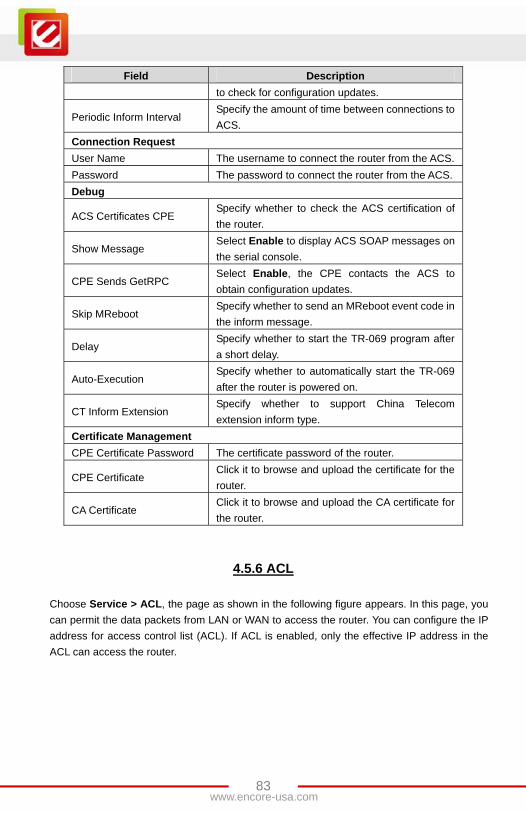
Field Description

to check for configuration updates.

Periodic Inform Interval Specify the amount of time between connections to

ACS.

Connection Request

User Name The username to connect the router from the ACS.

Password The password to connect the router from the ACS.

Debug

ACS Certificates CPE Specify whether to check the ACS certification of

the router.

Show Message Select Enable to display ACS SOAP messages on

the serial console.

CPE Sends GetRPC Select Enable, the CPE contacts the ACS to

obtain configuration updates.

Skip MReboot Specify whether to send an MReboot event code in

the inform message.

Delay Specify whether to start the TR-069 program after

a short delay.

Auto-Execution Specify whether to automatically start the TR-069

after the router is powered on.

CT Inform Extension Specify whether to support China Telecom

extension inform type.

Certificate Management

CPE Certificate Password The certificate password of the router.

CPE Certificate Click it to browse and upload the certificate for the

router.

CA Certificate Click it to browse and upload the CA certificate for

the router.

4.5.6 ACL

Choose Service > ACL, the page as shown in the following figure appears. In this page, you

can permit the data packets from LAN or WAN to access the router. You can configure the IP

address for access control list (ACL). If ACL is enabled, only the effective IP address in the

ACL can access the router.

84www.encore-usa.com

The following table describes the parameters and buttons in this page:

Field Description

Direction Select the router interface. You can select LAN or WAN. In

this example, LAN is selected.

LAN ACL Enable or disable ACL. You need to enable it, if you want to

use ACL and configure the parameters.

IP Address

Enter the IP address of the specified interface. Only the IP

address that is in the same network segment with the IP

address of the specified interface can access the router.

Services Allowed

You can select the following services from LAN or WAN:

Web, Telnet, FTP, TFTP, SNMP, or PING. You can also

select all the services.

Add After setting the parameters, click it to add the Current ACL

Table.

Reset Click it to refresh this page.

Set direction of the data packets to WAN, the page as shown in the following figure appears.

85www.encore-usa.com

The following table describes the parameters and buttons in this page:

Field Description

Direction Select the router interface. You can select LAN or WAN. In

this example, WAN is selected.

WAN Setting You can select Interface or IP address.

WAN Interface Select the interface that permits data packets from WAN to

access the router.

IP Address

Enter the IP address in the WAN. Only the IP address that is

in the same network segment with the IP address in the

WAN can access the router.

Services Allowed

You can select the following services from WAN: Web,

Telnet, FTP, TFTP, SNMP, or PING. You can also select all

the services.

Add After setting the parameters, click it to add an entry to the

Current ACL Table.

Reset Click it to refresh this page.

86www.encore-usa.com

4.6 Advance

In the navigation bar, click Advance. The Advance page that is displayed contains Bridge

Setting, Routing, Port Mapping, QoS, SNMP, and Others settings

4.6.1 Bridge Setting

Choose Advance > Bridge Setting, the page as shown in the following figure appears. This

page is used to configure the bridge parameters. In this page, you can modify the settings or

view some information of the bridge and its attached ports.

The following table describes the parameters and button in this page:

Field Description

Aging Time If the host is idle for 300 seconds (the default value), its entry

is deleted from the bridge table.

802.1D Spanning

Tree Protocol

(STP)

Disable or Enable 802.1d Spanning Tree Protocol (STP).

Select Enable to provide path redundancy while preventing

undesirable loops in your network.

Show MACs Click it to show a list of the learned MAC addresses for the

bridge.

Click Show MACs, the page as shown in the following figure appears. This table shows a list

of learned MAC addresses for this bridge.

87www.encore-usa.com

4.6.2 Routing

Choose Advance > Routing. The Routing page that is displayed contains Static Route and

RIP settings.

4.6.2.1 Static Route

Click Static Route, the page as shown in the following figure appears. In this page, you can

configure the routing information. You can add or delete IP routes.

The following table describes the parameters and buttons in this page:

Field Description

Enable Select it to use static IP routes.

Destination Enter the IP address of the destination device.

Subnet Mask Enter the subnet mask of the destination device.

Next Hop Enter the IP address of the next hop in the IP route to the

destination device.

Metric The metric cost for the destination.

Interface Select the interface for the specified route.

Add Route Click it to add the new static route to the Static Route Table.

Update Select a row in the Static Route Table and modify the

parameters. Then click it to save the settings in this page

88www.encore-usa.com

Field Description

temporarily.

Delete

Selected

Select a row in the Static Route Table and click it to delete the

row.

Show

Routes

Click it, the IP Route Table appears. You can view a list of

destination routes commonly accessed by your network.

Static Route

Table A list of the previously configured static IP routes.

Click Show Routes, the table as shown in the following figure appears. The table shows a

list of destination routes commonly accessed by your network.

4.6.2.2 RIP

Click RIP, the page as shown in the following figure appears. If the device is used as a

RIP-enabled router to communicate with other devices by using Routing Information

Protocol (RIP), you need to enable RIP. In this page, you can configure the parameters of

RIP, including the interface, received version, transmitted version.

89www.encore-usa.com

The following table describes the parameters and buttons in this page:

Field Description

RIP Select Enable, the router communicates with other

RIP-enabled devices.

Apply Changes Click it to save the settings in this page temporarily.

Interface Select the interface of the router that uses RIP.

Receive Version Select the interface version that receives RIP messages.

You can select RIP1, RIP2, or Both.

RIP1 indicates that the router receives RIP v1

messages.

RIP2 indicates that the router receives RIP v2

messages.

Both indicates that the router receives both of RIP v1

and v2 messages.

Send Version Select the working mode for sending RIP messages. You

can select RIP1 or RIP2.

RIP1 indicates that the router broadcasts RIP v1

messages only.

RIP2 indicates that the router multicasts RIP v2

messages only.

Add Click it to add a specified RIP interface to the RIP

Configuration List.

Delete Select a row in the RIP Configuration List and click it to

delete the row.

RIP Configuration

List

A list of the router interfaces that enable RIP.

4.6.3 Port Mapping

Choose Advance > Port Mapping, the page as shown in the following figure appears. In this

page, you can bind the WAN interface and the LAN interface into the same group.

90www.encore-usa.com

The procedure for operating a mapping group is as follows:

Step 1 Enable port mapping.

Step 2 Select a group from the table.

Step 3 Select the interfaces from the WAN and LAN and bind the required interfaces into

an interface group by clicking the arrow button.

Step 4 Click Apply Changes to take the settings into effect.

Note:

The selected interfaces are removed from the original groups and added to a new group.

91www.encore-usa.com

4.6.4 QoS

Choose Advance > QoS, the page as shown in the following figure appears. Entries in this

table are used to assign the precedence for each incoming packet according to physical LAN

port, TCP/UDP port number, source IP address, destination IP address, and other

information.

The procedure for configuring quality of service (QoS) is as follows:

Step 1 Enable IP QoS and click Apply to enable IP QoS.

Step 2 Click Add Rule to add a new IP QoS rule.

92www.encore-usa.com

The page as shown in the following figure appears.

The following table describes the parameters and buttons in this page:

Field Description

IP QoS Disable or enable QoS. By default, IP QoS is disabled. You

need to enable IP QoS, and then you can configure the

parameters in this page.

QoS Policy You can select Stream based, 802.1p based, or DSCP

based.

Schedule Mode You can select Strict prior or WFQ (4:3:2:1).

Source IP Enter the IP address of the source data packet.

Source Mask Enter the subnet mask of the source IP address.

Destination IP Enter the IP address of the destination data packet.

Destination

Mask

Enter the subnet mask of the destination IP address.

Source Port Enter the port of the source data packet.

93www.encore-usa.com

Field Description

Destination Port Enter the port of the destination data packet.

Protocol The protocol responds to the IP QoS rules. You can select

TCP, UDP, or ICMP.

Physical Port The LAN interface responds to the IP QoS rules, including

four LAN interfaces, one AP interface, and four VAP

interfaces.

Set Priority The priority of the IP QoS rules. P0 is the highest priority

and P3 is the lowest.

IP Precedence Set the priority in the ToS of the IP data packet. The priority

is in the range of 0 to 7.

IP ToS The type of IP ToS for classifying the data package

You can select Normal Service, Minimize Cost, Maximize

Reliability, Maximize Throughput, or Minimize Delay. 802.1p The priority is in the range of 0 to 7.

Delete Select a row in the QoS Rule List and click it to delete the

row.

Delete All Select all the rows in the QoS Rule List and click it to delete

the rows.

4.6.5 SNMP

Choose Advance > SNMP, the page as shown in the following figure appears. In this page,

you can configure the parameters of Simple Network Management Protocol (SNMP).

94www.encore-usa.com

By default, SNMP is disabled. Check the option of Enable SNMP, the page as shown in

the following figure appears.

The following table describes the parameters in this page:

Field Description

Enable SNMP

eck it to enable SNMP. You need to enable SNMP if

you want to use SNMP and configure the

parameters in this page.

Trap IP Address Enter the IP address of trap host. The trap

information is sent to the host.

Community name

(Read-only)

The network administrators must use this password

to read the information of this router.

Community name

(Read-Write)

The network administrators must use this password

to configure the information of the router.

4.6.6 Others

Choose Advance > Others, the page as shown in the following figure appears. In this page, you

can configure half bridge.

95www.encore-usa.com

96www.encore-usa.com

4.7 Admin

In the navigation bar, click Admin. The Admin page that is displayed contains Commit/Reboot,

Upgrade, System Log, Password, and Time Zone settings.

4.7.1 Commit/Reboot

Choose Admin > Commit/Reboot, the page as shown in the following figure appears. In this

page, you can reset the router to the factory default configuration, save the current configuration

or restart the router.

The following table describes the parameter and button in this page:

Field Description

Reboot from

You can select Save the current configuration or

Restore to the factory default configuration.

Save the current configuration: Save the

current configuration, and then the router

automatically reboots.

Restore to the factory default configuration:

Reset to the factory default configuration, and then

the the router automatically reboots.

Reboot Click it to reboot the router.

97www.encore-usa.com

4.7.2 Upgrade

Choose Admin > Upgrade. The Upgrade page that is displayed contains Upgrade Firmware

and Backup/Restore functions.

4.7.2.1 Upgrade Firmware

Click Upgrade Firmware, the page as shown in the following figure appears. In this page, you

can upgrade the firmware of the router.

Caution:

Do not turn off the router or press the Reset button while the procedure is in

progress. Otherwise, it may crash the system.

The following table describes the parameter and buttons in this page:

Field Description

Select File Click Browse to select the firmware file.

Upload After selecting the firmware file, click it to starting

upgrading the firmware file.

Reset Click it to start selecting the firmware file again.

98www.encore-usa.com

4.7.2.2 Backup/Restore

Click Backup/Restore, the page as shown in the following figure appears. In this page, you can

back up the current configuration to a file and restore the configuration from the file that was

saved previously.

Caution:

Do not turn off the router or press the Reset button while the procedure is in

progress. Otherwise, it may crash the system.

The following table describes the parameters and buttons in this page:

Field Description

Save Settings to

File

Click Save to select the path for backup. Then you can

save the configuration file of the router.

Load Settings from

File Click Browse to select the configuration file.

Upload After selecting the configuration file of the router, click it to

start uploading the configuration file of the router.

99www.encore-usa.com

4.7.3 System Log

Choose Admin > System Log, the page as shown in the following figure appears. In this page,

you can view the system log according to the log level.

4.7.4 Password

Choose Admin > Password, the page as shown in the following figure appears. In this page,

you can change the password of the user. By default, the user name and password of the super

user are admin and admin respectively. The user name and password of the common user are

user and user respectively.

100www.encore-usa.com

The following table describes the parameters in this page:

Field Description

User Name Select the user name for accessing the router. You can

select admin or user from the drop-down list.

New Password Enter the password to which you want to change the old

password.

Confirmed Password Enter the new password again.

Restore to the

Default Password

Select it, and the password will be restored to the default

password.

4.7.5 Time Zone

Choose Admin > Time Zone, the page as shown in the following figure appears. In this page,

you can set the system time manually or obtain the system time from the time server.

The following table describes the parameters in this page:

Field Description

System Time Set the system time manually.

NTP Configuration

State Enable or disable NTP. You need to enable NTP if you

want to configure the parameters of NTP.

101www.encore-usa.com

Field Description

Primary Server Set the primary NTP server manually.

Secondary Server Set the secondary NTP server manually.

Time Zone Select the time zone in which area you are from the

drop-down list.

102www.encore-usa.com

Chapter 5 Diagnostic

In the navigation bar, click Diagnostic. The Diagnostic page that is displayed contains

Ping, ATM Loopback, ADSL and Diagnostic Test tools.

5.1 Ping

Choose Diagnostic > Ping, the page as shown in the following figure appears.

The following table describes the parameter and button in this page:

Field Description

Host Enter the IP address.

Ping Click it to start to ping the host address.
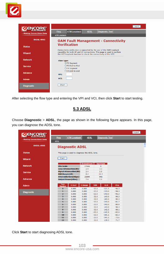
5.2 ATM Loopback

Choose Diagnostic > ATM Loopback, then the page as shown in the following figure appears.

In this page, you can use VCC loopback to check the connectivity of the VCC. The ATM

loopback test is useful for troubleshooting problems with the DSLAM and ATM network.

103www.encore-usa.com

After selecting the flow type and entering the VPI and VCI, then click Start to start testing.

5.3 ADSL

Choose Diagnostic > ADSL, the page as shown in the following figure appears. In this page,

you can diagnose the ADSL tone.

Click Start to start diagnosing ADSL tone.

104www.encore-usa.com

5.4 Diagnostic Test

Choose Diagnostic > Diagnostic Test, the page as shown in the following figure appears.

In this page, you can test the ADSL connection. You can also view the LAN connection,

WLAN connection, ADSL connection, and Internet connection.

Click Run Diagnostic Test to start testing.

105www.encore-usa.com

Appendix A Frequently Asked Questions

This Frequently Asked Questions addresses common questions regarding Wireless ADSL 2+

Modem Router settings.

Some of these questions are also found throughout the guide, in the sections to which they

are referenced.

(1) How do I determine if a link has been established between the Ethernet card

(NIC) and the Wireless ADSL 2+ Modem Router?

Answer. A ping test would determine if a connection is established between your Wireless

ADSL 2+ Modem Router and computer. Using, the ping command, ping the IP address of the

Wireless ADSL 2+ Modem Router, in this case, 192.168.1.1 (default). For more information

on Ping Testing, refer to Appendix C: Troubleshooting Guide. Alternatively, if the Ethernet

LINK LED is solidly on, then the Ethernet link is established.

(2) How do I determine if a link has been established between the Wireless ADSL 2+

Modem Router and the Internet?

Answer. Similar to the previous question, a ping test would determine whether or not a

connection is established. However, this time use a URL instead of and IP Address, such as

www.google.com. Alternatively, if the ADSL LED is solidly on, then the ADSL link is

established.

(3) How can I find/verify Ethernet MAC Addresses of my Wireless ADSL 2+ Modem

Router and/or computer?

Answer. Refer to Status – Info section for details.

(4) I can’t get the Internet game, server, or application to work properly.

Answer. If you are having difficulties getting any Internet game, server, or application to

function properly, consider exposing one computer to the Internet using De-Militarized Zone

(DMZ) setting. Refer to Advance – Port Forwarding section for the setting detail.

(5) I need to upgrade the firmware.

Answer. In order to upgrade the firmware with the latest features, check with your local

dealer or ISP for technical support.

106www.encore-usa.com

(6) I forgot my password.

Answer. Reset the Wireless ADSL 2+ Modem Router to factory default by pressing the

Reset button for 5~10 seconds and then releasing it.

If you are still getting prompted for a password when saving settings, then perform the

following steps:

1. Access the Wireless ADSL 2+ Modem Router’s web-based utility by going

to http://192.168.1.1 or the IP address of the Wireless ADSL 2+ Modem

Router. Enter the default username and password admin, and click the

Tools – User Management tab.

2. Enter a different password in the Wireless ADSL 2+ Modem Router

Password field, and enter the same password in the second field to confirm

the password.

3. Click the Submit button then click SAVE button to activate your setting.

(7) What is MAC Address?

Answer. The MAC is short for Media Access Control Address. It is a hardware address that

uniquely identifies each node of an Ethernet networking device. This address is usually

permanent.

(8) What is NAT (Network Address Translation) and what is it used for?

Answer. NAT translates multiple IP Addresses on the private LAN to one public IP Address

(in WAN) that is connected to the Internet. NAT adds a level security since the IP address of a

computer connected to the private LAN is never transmitted on the Internet.

(9) What can I do when I am not able to get the web configuration page shown for

this Wireless ADSL 2+ Modem Router?

Answer. Remove the proxy settings on your Internet Browsers or remove the dial-up

settings on your browser.

(10) What is DMZ (De-Militarized zone)?

Answer. DMZ allows one IP Address (computer) to be exposed to the Internet. Some

applications require multiple TCP/IP ports to be opened. It is recommended that you set your

computer with static IP address if you want to use DMZ features. And, be aware to add extra

protection and security to the computer exposed.

107www.encore-usa.com

(11) What is the maximum number of local IP addresses supported by this Wireless

ADSL 2+ Modem Router?

Answer. The Wireless ADSL 2+ Modem Router can support up to 253 IP addresses in one

Class C IP domain.

(12) What is ad-hoc mode?

Answer. When a wireless network is set to be ad-hoc mode, the wireless-equipped

computers are configured to communicate directly with each other, peer-to-peer, without the

use of an access point.

(13) What is infrastructure mode?

Answer. When a wireless network is set to be infrastructure mode, the wireless network is

configured to communicate with a network through a wireless access point.

(14) What is roaming?

Answer. Roaming is the ability of a portable computer user to communicate continuously

while moving freely throughout an area greater than that covered by a single access point.

Before using the roaming function, the computer must make sure that it is the same channel

number with the access point of dedicated coverage area.

(15) What is ISM band?

Answer. The FCC and their counterparts outside of the U.S. have set aside bandwidth for

unlicensed use in the ISM (Industrial, Scientific and Medical) band. Spectrum in the vicinity of

2.4 GHz, in particular, is being made available worldwide. This presents a truly revolutionary

opportunity to place convenient high-speed wireless capabilities in the hands of users around

the globe.

(16) What is IEEE 802.11b standard?

Answer. IEEE 802.11b is an extension standard to 802.11 that applies to Wireless LAN and

provides maximum 11Mbps transmission speed in the 2.4 GHz band.

(17) What is IEEE 802.11g standard?

Answer. IEEE 802.11g is an extension standard to 802.11 that applies to Wireless LAN and

provides maximum 54Mbps transmission speed in the 2.4 GHz band.

(18) What is BSS ID?

Answer. A specific Ad-Hoc LAN is called a Basic Service Set (BSS). Computers in a BSS

must be configured with the same BSS ID.

108www.encore-usa.com

(19) What is SSID?

Answer. Short for Service Set Identifier. SSID is a 32 character unique identifier attached to

the header of packets sent over a WLAN that acts as a password when a mobile device tries

to connect to the BSS. The SSID differentiates one WLAN from another, so all Access Point

and all devices attempting to connect to a specific WLAN must use the same SSID. A device

will not be permitted to join the BSS unless it can provide the unique SSID.

(20) What is WEP?

Answer. It is short for Wired Equivalent Privacy. WEP is a security protocol for wireless

local area networks defined in the 802.11b standard. WEP is designed to provide the same

level of security as that of a wired LAN. WEP aims to provide security by encrypting data over

radio waves so that it is protected as it is transmitted from one end point to another.

(21) What is WPA?

Answer. Wi-Fi Protected Access (WPA) is a specification of standards-based, interoperable

security enhancements that increase the level of data protection and access control for

existing and future wireless LAN systems.

(22) Where could I get more product information or technical supports?

Answer. Please check the Support section on our web site http://www.encore-usa.com.

109www.encore-usa.com

Appendix B Troubleshooting Guide

This Troubleshooting Guide provides answers to common problems regarding the Wireless

ADSL 2+ Modem Router settings, connections, and computer settings.

(1) The Wireless ADSL 2+ Modem Router does not work (None of the LEDs light up)

Answer. Check the following:

1. Make sure that you are using the correct power adapter for your Wireless

ADSL 2+ Modem Router device.

2. Make sure that the power adapter is plugged into a power socket.

3. Make sure the power switch is on if you are using the power extension cable.

(2) I changed the LAN IP Address in the LAN configuration page and my PC is no

longer able to detect the Wireless ADSL 2+ Modem Router.

Answer. After changing the LAN IP Address of the Wireless ADSL 2+ Modem Router,

proceed to the following steps to refresh IP address of the PC before the PC is able to

recognize the Wireless ADSL 2+ Modem Router:

1. Click “Start” “Run”.

2. In the Open field, enter “cmd” then click “OK”.

3. In the command prompt, type “ipconfig/release” and then press “Enter”

(for Windows 2000/XP Operating System).

4. Type “ipconfig/renew” then press “Enter”.

(3) LAN (Link/Act) LED does not light up.

Answer. Check the following:

1. Make sure that the LAN cables are securely connected to the 10/100Base-T

port.

2. Make sure that you are using the correct cable type for your Ethernet

equipment.

3. Make sure the computer's Ethernet port is configured for auto-negotiation.

110www.encore-usa.com

(4) Failed to configure the Wireless ADSL 2+ Modem Router through web browser

(By a client PC in LAN)

Answer. Check the following:

1. Check the hardware connection of the Wireless ADSL 2+ Modem Router’s

LAN port. The LED will light when a proper connection is made.

2. Check your Windows TCP/IP setting. (Refer to Chapter 3 for setting details).

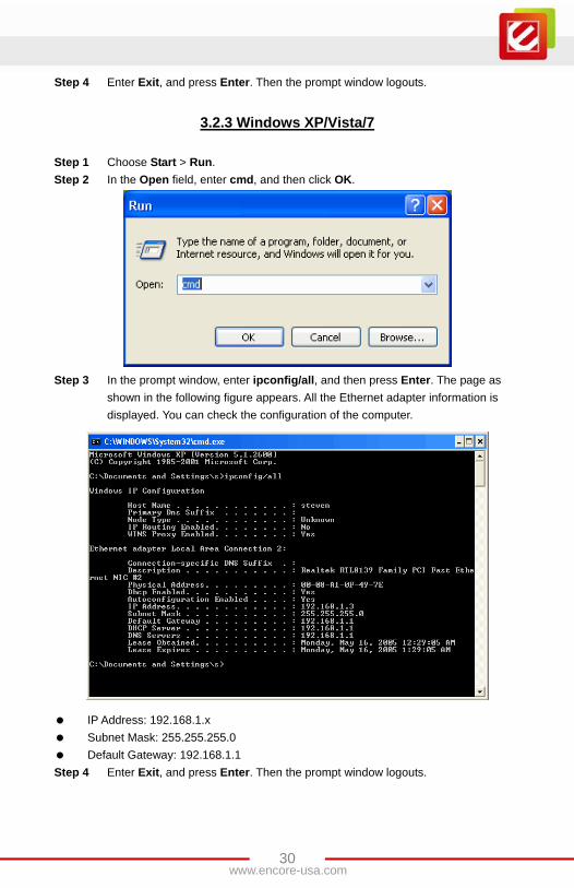
3. Open the Windows System Command Prompt:

– For Windows 9x/ME: Manually enter “winipcfg”, then press Enter.

– For Windows 2000/XP: Manually enter “ipconfig/all”, then press Enter”.

4. You should have the following information listed on your Window System:

– IP Address: 192.168.1.x

– Subnet Mask: 255.255.255.0

– Default Gateway IP: 192.168.1.1

(5) I forgot or lost my Administrator Password.

Answer. Reset the Wireless ADSL 2+ Modem Router to factory default by pressing the

“Reset” button for 5~10 seconds.

If you are still getting prompted for a password when saving settings:

1. Access the Router’s web interface by going to http://192.1681.1.

2. Enter the default “username” and “password”, and then clicks “Enter” to

login.

3. Click on “Tools” and then click “User Management”.

4. Enter a new “Password” and new “Username” in the “Username” and

“Password” fields, and enter the same password in the second password

field to confirm the password.

5. Click “Submit” after setup then click SAVE button to activate your setting.

111www.encore-usa.com

(6) I need to upgrade the Firmware.

Answer. In order to upgrade the Firmware with the latest features, check your local dealer

or ISP for technical support. Before proceed the upgrading process, check the following

details:

1. Download the latest Firmware and save at your pointed location.

2. Read the firmware release note carefully before proceed the upgrading

process.

3. Refer to Tools - Update section for the upgrading process.

(7) Testing LAN path to your Wireless ADSL 2+ Modem Router.

Answer. To verify whether the LAN path from your PC to your Wireless ADSL 2+ Modem

Router is properly connected, you can “Ping” the LAN IP address of Wireless ADSL 2+

Modem Router with the following procedure:

1. From the Windows toolbar, click “Start” and select “Run”.

2. In the Open field, type “Ping 192.168.1.1” and click “OK”.

3. If the path is working, you should see the message in the following format:

Reply from 192.168.1.1 bytes = 32 time < 10ms TTL = 60

4. If the path is not working, you should see the following message:

Request timed out

If the path is not functioning correctly:

1. Make sure the LAN port LED indicator is on.

2. Check whether you are using the correct LAN cable.

3. Check your Ethernet adapter installation and configurations.

4. Verify that the IP addresses for your Wireless ADSL 2+ Modem Router and

your workstations are correct and the IP addresses are on the same subnet.

112www.encore-usa.com

(8) No wireless connectivity.

Answer. Check the following:

1. Make sure that both of wireless client adapter and the Wireless ADSL 2+

Modem Router are allowed to connect through wireless channels as defined

for local regulatory domain.

2. Make sure that the WLAN client is configured for the correct wireless settings

(SSID, WEP).

(9) Poor wireless connectivity or range reachable.

Answer. Check the following:

1. Choose automatic channel selection or be careful to select a channel that

doesn't interfere with other radio channels.

2. Check the location of the Wireless ADSL 2+ Modem Router in the building.

3. Make sure that both of WLAN client adapter and the Wireless ADSL 2+

Modem Router are allowed to connect through wireless channels as

defined for local regulatory domain.

(10) Failed to connect with the Wireless ADSL 2+ Modem Router via Wireless LAN

card.

Answer. Ensure that the WL ACT LED indicator of the Wireless ADSL 2+ Modem Router is

correctly illuminated.

Check whether your Wireless LAN settings (e.g. SSID, Channel Number) are the same as

your Wireless ADSL 2+ Modem Router.

Check whether you have used the same WEP Key Encryption for both your Wireless LAN

client and your Wireless ADSL 2+ Modem Router

113www.encore-usa.com

Appendix C Glossary

The Glossary provides an explanation of terms and acronyms discussed in this user guide.

10BASE-T: IEEE 802.3 specification for 10 Mbps Ethernet over twisted pair wiring.

100BASE-Tx: IEEE 802.3 specification for 100 Mbps Ethernet over twisted pair wiring.

802.11b: IEEE specification for wireless networking at 11 Mbps using direct-sequence

spread-spectrum (DSSS) technology and operating in the unlicensed radio spectrum at

2.4GHz.

802.11g: IEEE specification for wireless networking at 54 Mbps using direct-sequence

spread-spectrum (DSSS) technology and operating in the unlicensed radio spectrum at

2.4GHz.

802.1x: The 802.1x defines port-based, network access control used to provide authenticated

network access and automated data encryption key management. The IEEE 802.1x draft

standard offers an effective framework for authenticating and controlling user traffic to a

protected network, as well as dynamically varying encryption keys.

AP: Access Point. It is a station that transmits and receives data in a WLAN (Wireless Local

Area Network). An access point acts as a bridge for wireless devices into a LAN.

ATM: Asynchronous Transfer Mode. It is a method of data transferring in which data is

organized into 53-byte cell units. ATM cells are processed asynchronously in relation to other

cells.

BC: Broadcast Communication. A sender transmits to everyone in the network.

BER: Bit Error Rate. It is the percentage of bits that contains errors relative to the total number

of bits transmitted.

Bridge: It is a device that connects two networks and decides which network the data should

go to.

Bridge Mode: The bridge mode is used when there is one PC connected to the LAN-side

Ethernet port of the ADSL device. The IEEE 802.1D method of transport bridging is used to

bridge between the WAN (ADSL) side and the LAN (Ethernet) side, i.e., to store and forward.

CBR: Constant Bit Rate. A constant transfer rates that is ideal for streaming (executing while

still downloading) data, such as audio or video files.

114www.encore-usa.com

Cell: A unit of transmission in ATM, consisting of a fixed-size frame containing a 5-octet

header and a 48-octet payload.

CHAP: Challenge Handshake Authentication Protocol. It is typically more secure than PAP

and CHAP. It uses username and password in combination with a randomly generated

challenge string, which has to be authenticated using a one-way hashing function.

CLP: Cell Loss Priority. ATM cells have two levels of priority, CLP0 and CLP1. CLP0 is of

higher priority, and in times of high traffic congestion, CLP1 error cells may be discarded to

preserve the Cell Loss Ratio of the CLP0 cells.

CO: Central Office. In a local loop, a Central Office is where home and office phone lines

come together and go through switching equipment to connect them to other Central Offices.

The distance from the Central Office determines whether or not an ADSL signal can be

supported in a given line.

CPE: Customer Premises Equipment. This specifies equipment on the customer end, or LAN

side.

CRC: Cyclic Redundancy Checking. It is a method for checking errors in a data transmission

between two computers or devices. CRC applies a polynomial function (16 or 32-bit) to a

block of data. The result of that polynomial is appended to the data transmission. Upon receipt,

the destination computer applies the same polynomial to the block of data. If the host and

destination computer share the same result, the transmission was successful. Otherwise, the

sender is notified to re-send the data block.

DHCP: Dynamic Host Configuration Protocol. It is a communications protocol that allows

network administrators to manage and assign IP addresses to computers within the network.

DHCP provides a unique address to a computer in the network, which enables it to connect to

the Internet through Internet Protocol (IP). DHCP can lease an IP address or provide a

permanent static address to those computers who need it (servers, etc.).

DMZ: Demilitarized Zone. It is a computer host or network that acts as a neutral zone

between a private network and a public network. A DMZ prevents users outside of the private

network from getting direct access to a server or any computer within the private network. The

outside user sends requests to the DMZ, and the DMZ initiates sessions in the public network

based on these requests. A DMZ cannot initiate a session in the private network; it can only

forward packets to the private network as they are requested.

DNS: Domain Name System: A method to locate and translate Domain Names into Internet

Protocol (IP) addresses, where a Domain Name is a simple and meaningful name for an

Internet address.

115www.encore-usa.com

DSCP: Differentiated Services Code Point. It is a 6-bit field defined in the header of IPv4 and

IPv6 IP packets for packet classification purposes.

DSL: Digital Subscriber Line: A technology that provides broadband connections over

standard phone lines.

DSLAM: Digital Subscriber Line Access Multiplexer: Using multiplexing techniques, a DSLAM

receives signals from customer DSL lines and places the signals on a high-speed backbone

line. DSLAMs are typically located at a telephone company’s CO (Central Office).

Encapsulation: The inclusion of one data structure within another. For example, packets can

be encapsulated in an ATM frame during transfer.

FEC: Forward Error Correction: An error correction technique in which a data packet is

processed through an algorithm that adds extra error correcting bits to the packet. If the

transmitted message is received in error, these bits are used to correct the error bits without

retransmission.

Firewall: A firewall is a method of implementing common as well as user defined security

policies in an effort to keep intruders out. Firewalls work by analyzing and filtering out IP

packets that violate a set of rules defined by the firewall administrator. The firewall is located

at the point of entry for the network. All data inbound and outbound must pass through the

firewall for inspection.

Fragmentation: To break a packet up into smaller packets that is caused either by the

transmission medium being unable to support the original size of the packet or the receiving

computer not being able to receive a packet of that size. Fragmentation occurs when the

sender’s MTU is larger than the receiver’s MRU.

FTP: File Transfer Protocol. It is a standardized Internet protocol, which is the simplest way to

transfer files from one computer to another over the Internet. FTP uses the Internet’s TCP/IP

protocols to function.

Full Duplex: Data can be transmitted and received on the same signal medium and at the

same time. Full Duplex lines are bidirectional.

G.dmt: Formally G.992.1, the G.dmt is a form of ADSL that uses Discrete Multi-Tone (DMT)

technology. G.dmt incorporates a splitter in its design.

116www.encore-usa.com

G.lite: Formally G.992.2, G.lite is a standard way to install ADSL service. G.lite enables

connections speeds up to 1.5 Mbps downstream and 128 kbps upstream. G.lite does not

need a splitter at the user end because splitting is preformed at the remote end (the telephone

company).

Gateway: A point on the network, which is an entrance to another network. For example, a

router is a gateway that connects a LAN to a WAN.

Half Duplex: Data can be transmitted and received on the same signal medium, but not

simultaneously. Half Duplex lines are bi-directional.

HEC: Headed Error Control: ATM error checking by using a CRC algorithm on the fifth octet in

the ATM cell header to generate a check character. Using HEC, either a single bit error in the

header can be corrected or multiple bit errors in the header can be detected.

HNP: Home Network Processor.

Host: In context of Internet Protocol, a host computer is one that has full two-way access to

other computers on the Internet.

IAD: Integrated Access Device: A device that multiplexes and de-multiplexes communications

in the CPE onto and out of a single telephone line for transmission to the CO.

IP: Internet Protocol: The method by which information is sent from one computer to another

through the Internet. Each of these host computers has a unique IP address which

distinguishes it from all the other computers on the Internet. Each packet of data sent includes

the sender’s IP address and the receiver’s IP address.

LAN: Local Area Network: A group of computers, typically covering a small geographic area,

that share devices such as printers, hard disk drives, scanners, and optical drives. Computers

in a LAN typically share an Internet connection through some sort of router that connects the

computers to a WAN.

LLC: Logical Link Control: Provides an interface point to the MAC sub-layer. LLC

Encapsulation is needed when several protocols are carried over the same Virtual Circuit.

MAC Address: Media Access Control Address: A unique hardware number on a network

interface adapter of computer or device that identifies it and relates it to the IP address of that

device.

MC: Multicast: Communication involving a single sender and multiple specific receivers in a

network.

117www.encore-usa.com

MRU: Maximum Receive Unit: MRU is the largest size packet that can be received by the

modem. During the PPP negotiation, the peer of the PPP connection will indicate its MRU and

will accept any value up to that size. The actual MTU of the PPP connection will be set to the

smaller of the two (MTU and the peer’s MRU). In the normal negotiation, the peer will accept

this MRU and will not send packet with information field larger than this value.

MSS: Maximum Segment Size: The largest size of data that TCP will send in a single

un-fragmented IP packet. When a connection is established between a LAN client and a host

in the WAN side, the LAN client and the WAN host will indicate their Maximum Segment Size

during the TCP connection handshake.

MTU: Maximum Transmission Unit: The largest size packet that can be sent by the modem. If

the network stack of any packet is larger than the MTU value, then the packet will be

fragmented before the transmission. During the PPP negotiation, the peer of the PPP

connection will indicate its MRU and will accept any value up to that size. The actual MTU of

the PPP connection will be set to the smaller of the two (MTU and the peer’s MRU).

NAPT: Network Address and Port Translation: An extension of NAT, NAPT maps many

private internal addresses into one IP address. The outside network (WAN) can see this one

IP address but it cannot see the IP addresses of individual devices translated by the NAPT.

NAT: Network Address Translation: The translation of an IP address of one network to a

different IP address known by another network. This gives an outside network (WAN) the

ability to distinguish a device on the inside network (LAN), as the inside network has a private

set of IP addresses assigned by the DHCP server not known to the outside network.

PAP: Password Authentication Protocol: An authentication protocol in which authorization is

done through a set of user name and password.

PDU: Protocol Data Unit: A frame of data transmitted through the data link layer 2.

Ping: Packet Internet Groper: A utility used to determine whether a particular device is online

or connected to a network by sending test packets and waiting for a response.

PPP: Point-to-Point Protocol: A method of transporting and encapsulating IP packets between

the user PC and the ISP. PPP is full duplex protocol that is transmitted through a serial

interface.

Proxy: A device that closes a straight connection from an outside network (WAN) to an inside

network (LAN). All transmissions must go through the proxy to get into or out of the LAN. This

makes the internal addresses of the devices in the LAN private.

118www.encore-usa.com

PVC: Permanent Virtual Circuit: The software defined logical connection in a network. A

Virtual Circuit that is permanently available to the user.

RIP: Routing Information Protocol: A management protocol that ensures that all hosts in a

particular network share the same information about routing paths. In a RIP, a host computer

will send its entire routing table to another host computer every X seconds, where X is the

supply interval. The receiving host computer will in turn repeat the same process by sending

the same information to another host computer. The process is repeated until all host

computers in a given network share the same routing knowledge.

RIPv1: RIP Version 1: One of the first dynamic routing protocols introduced used in the

Internet, RIPv1 was developed to distribute network reach ability information for what is now

considered simple topologies.

RIPv2: RIP Version 2: Shares the same basic concepts and algorithms as RIPv1 with added

features such as subnet masks, authentication, external route tags, next hop addresses, and

multicasting in addition to broadcasting.

Router Mode: Router Mode is used when there is more than one PC connected to the

LAN-side Ethernet port of the ADSL device. This enables the ADSL WAN access to be shared

with multiple nodes on the LAN. Network Address Translation (NAT) is supported, so that one

WAN-side IP address can be shared among multiple LAN-side devices. DHCP is used to

serve each LAN-side device an IP address.

SNAP: Sub-Network Attachment Point.

SNMP: Simple Network Management Protocol: Used to govern network management and

monitor devices on the network. SNMP is formally described in RFC 1157.

SNR: Signal-to-Noise Ratio: Measured in decibels, SNR is a calculated ratio of signal strength

to background noise. The higher this ratio is, the better the signal quality is.

Subnet Mask: Short for Sub-Network Mask, subnet mask is a technique used by the IP

protocol to filter messages into a particular network segment, called a subnet. The subnet

mask consists of a binary pattern that is stored in the client computer, server, or router. This

pattern is compared with the incoming IP address to determine whether to accept or reject the

packet.

TCP: Transfer Control Protocol: Works together with Internet Protocol for sending data

between computers over the Internet. TCP keeps track of the packets, making sure that they

are routed efficiently.

119www.encore-usa.com

TFTP: Trivial File Transfer Protocol: A simple version of FTP protocol that has no password

authentication or directory structure capability.

ToS: type of service. It is a byte defined in the IPv4 header which is used for various purposes

over the years and mostly for the IP precedence.

Trellis Code: An advanced method of FEC (Forward Error Correction). When enabled, it

makes for better error checking at the cost of slower packet transmission. Setting Trellis Code

to be disabled will cause increased packet transmission with decreased error correction.

TTL: Time To Live: A value in an IP packet that indicates whether or not the packet has been

propagating through the network too long and should be discarded.

UBR: Unspecified Bit Rate: A transfer mode that is usually used in file transferring, email, etc.

UBR can vary depending on the data type.

USB: Universal Serial Bus: A standard interface between a computer and a peripheral (printer,

external drives, digital cameras, scanners, network interface devices, modems, etc.) that

allows data transferring.

UDP: User Datagram Protocol: A protocol that is used instead of TCP when reliable delivery

is not required. Unlike TCP, UDP does not require an acknowledgement (handshake) from

the receiving end. UDP sends packets in one-way transmissions.

VBR-nrt: Variable Bit Rate – non real time: With VBR-nrt, cell transfer is variable upon certain

criteria.

VC: Virtual Circuit: A virtual circuit is a circuit in a network that appears to be a physically

discrete path, but is actually a managed collection of circuit resources that allocates specific

circuits as needed to satisfy traffic requirements.

VCI: Virtual Channel Identifier: A virtual channel identified by a unique numerical tag that is

defined by a 16-bit field in the ATM cell header. The purpose of the virtual channel is to

identify where the cell should travel.

VC-Mux: Virtual Circuit based Multiplexing: In VC Based Multiplexing, the interconnect

protocol of the carried network is identified implicitly by the VC (Virtual Circuit) connecting the

two ATM stations (each protocol must be carried over a separate VC).

VPI: Virtual Path Identifier: Virtual path for cell routing indicated by an eight bit field in the ATM

cell header.

120www.encore-usa.com

WAN: Wide Area Network: A WAN covers a large geographical area. A WAN is consisted of

LANs, and the Internet is consisted of WANs.

WFQ: weighted fair queuing. It is a data packet scheduling technique which allows different

data flows to be queued in different priorities.

WPA: Wi-Fi Protected Access (WPA) is a specification of standards-based, interoperable

security enhancements that increase the level of data protection and access control for

existing and future wireless LAN systems.

121www.encore-usa.com

Appendix D Regulatory notes and statements

Wireless LAN, Health and Authorization for use

Radio frequency electromagnetic energy is emitted from Wireless LAN devices. The energy levels of these emissions however are far much less than the electromagnetic energy emissions from wireless devices like for example mobile phones. Wireless LAN devices are safe for use frequency safety standards and recommendations. The use of Wireless LAN devices may be restricted in some situations or environments for example:

·On board of airplanes, or

·In an explosive environment, or

·In case the interference risk to other devices or services is perceived or identified as harmful

In case the policy regarding the use of Wireless LAN devices in specific organizations or environments (e.g. airports, hospitals, chemical/oil/gas industrial plants, private buildings etc.) is not clear, please ask for authorization to use these devices prior to operating the equipment.

Regulatory Information/disclaimers

Installation and use of this Wireless LAN device must be in strict accordance with the instructions included in the user documentation provided with the product. Any changes or modifications made to this device that are not expressly approved by the manufacturer may void the user’s authority to operate the equipment. The Manufacturer is not responsible for any radio or television interference caused by unauthorized modification of this device, of the substitution or attachment. Manufacturer and its authorized resellers or distributors will assume no liability for any damage or violation of government regulations arising from failing to comply with these guidelines.

USA-FCC (Federal Communications Commission) statement

This device complies with Part 15 of FCC Rules.

Operation is subject to the following two conditions:

1. This device may not cause interference, and

2. This device must accept any interference, including interference that may cause undesired operation of this device.

122www.encore-usa.com

FCC Radio Frequency Exposure statement

This Wireless LAN radio device has been evaluated under FCC Bulletin OET 65 and found compliant to the requirements as set forth in CFR 47 Sections 2.1091, 2.1093, and 15.247 (b) (4) addressing RF Exposure from radio frequency devices. The radiated output power of this Wireless LAN device is far below the FCC radio frequency exposure limits. Nevertheless, this device shall be used in such a manner that the potential for human contact during normal operation is minimized.

When nearby persons has to be kept to ensure RF exposure compliance, in order to comply with RF exposure limits established in the ANSI C95.1 standards, the distance between the antennas and the user should not be less than 20 cm.

FCC Interference Statement

This equipment has been tested and found to comply with the limits for a Class B digital device, pursuant to Part 15 of the FCC Rules. These limits are designed to provide reasonable protection against harmful interference in a residential installation.

This equipment generates, uses, and can radiate radio frequency energy. If not installed and used in accordance with the instructions, it may cause harmful interference to radio communications.

However, there is no guarantee that interference will not occur in a particular installation. If this equipment does cause harmful interference to radio or television reception, which can be determined by turning the equipment off and on, the user is encouraged to try and correct the interference by one or more of the following measures:

1. Reorient or relocate the receiving antenna.

2. Increase the distance between the equipment and the receiver.

3. Connect the equipment to an outlet on a circuit different from that to which the receiver is connected.

4. Consult the dealer or an experienced radio/TV technician for help.

Export restrictions

This product or software contains encryption code that may not be exported or transferred from the US of Canada without an approved US Department of Commerce export license.

Safety Information

Your device contains a low power transmitter. When device is transmitted it sends out radio frequency (RF) signal.

CAUTION: To maintain compliance with FCC’s RF exposure guidelines, this equipment should be installed and operated with minimum distance 20cm between the radiator and your body. Use on the supplied antenna. Unauthorized antenna, modification, or attachments could damage the transmitter and may violate FCC regulations.

The antenna(s) used for this transmitter must be installed to provide a separation distance of at least 20 cm from all persons and must not be co-located or operating in conjunction with any other antenna or transmitter.

CE Mark Warning

This is a Class B product. In a domestic environment, this product may cause radio interference, in which case the user may be required to take adequate measures.

123www.encore-usa.com

Protection requirements for health and safety – Article 3.1a

Testing for electric safety according to EN 60950 has been conducted. These are considered relevant and sufficient.

Protection requirements for electromagnetic compatibility (EMC) – Article 3.1b

Testing for electromagnetic compatibility according to EN 301 489-1, EN 301 489-17 and EN 55024 has been conducted. These are considered relevant and sufficient.

Effective use of the radio spectrum – Article 3.2

Testing for radio test suites according to EN 300 328 has been conducted. These are considered relevant and sufficient.

CE in which Countries where the product may be used freely:

Germany, UK, Italy, Spain, Belgium, Netherlands, Portugal, Greece, Ireland, Denmark, Luxembourg, Austria, Finland, Sweden, Norway and Iceland.

France: except the channel 10 through 13, law prohibits the use of other channels.

Caution The Federal Communication Commission warns the user that changes or modifications to the device not expressly approved by the party responsible for compliance could void the user’s authority to operate the equipment.

Copyright

The company has an on-going policy of upgrading its products and it may be possible that information in this document is not up-to-date. Please check with your local distributors for the latest information.

The contents of this publication may not be reproduced in any part or as a whole, stored, transcribed in an information retrieval system, translated into any language, or transmitted in any form or by any means, mechanical, magnetic, electronic, optical, photocopying, manual, or otherwise, without the prior written permission or consent from the company.

Trademarks All products, companies and brand names are trademarks or registered trademarks of their respective companies. They are used for identification purpose only.

124www.encore-usa.com

Product specifications, size, and shape are subject to change without notice, and actual product appearance may differ from that depicted herein.

All trademarks and brand names are the properties of their respective holders.

* Local tech-support numbers are provided in selectively countries. Service may change without prior notice.

Please visit www.encore-usa.com for more details.


Recommended