+ All Categories
Home > Documents > Manual Drivetrains and Axles CHAPTER Manual Drivetrains and Axles, 7e James D. Halderman | Tom Birch...

Manual Drivetrains and Axles CHAPTER Manual Drivetrains and Axles, 7e James D. Halderman | Tom Birch...

Date post: 13-Dec-2015
Category:
Upload: wesley-caldwell
View: 237 times
Download: 1 times
Share this document with a friend
Popular Tags:
27
Manual Drivetrains and Axles Manual Drivetrains and Axles CHAPTER Manual Drivetrains and Axles, 7e James D. Halderman | Tom Birch SEVENTH EDITION Copyright © 2015 by Pearson Education, Inc. All Rights Reserved Clutch Parts and Operation 4
Transcript

Manual Drivetrains and AxlesManual Drivetrains and Axles

CHAPTER

Manual Drivetrains and Axles, 7eJames D. Halderman | Tom Birch

SEVENTH EDITION

Copyright © 2015 by Pearson Education, Inc.All Rights Reserved

Clutch Parts and Operation

4

Manual Drivetrains and Axles, 7eJames D. Halderman | Tom Birch

Copyright © 2015 by Pearson Education, Inc.All Rights Reserved

Figure 4–1 Typical automotive clutch assembly showing all related parts.

Manual Drivetrains and Axles, 7eJames D. Halderman | Tom Birch

Copyright © 2015 by Pearson Education, Inc.All Rights Reserved

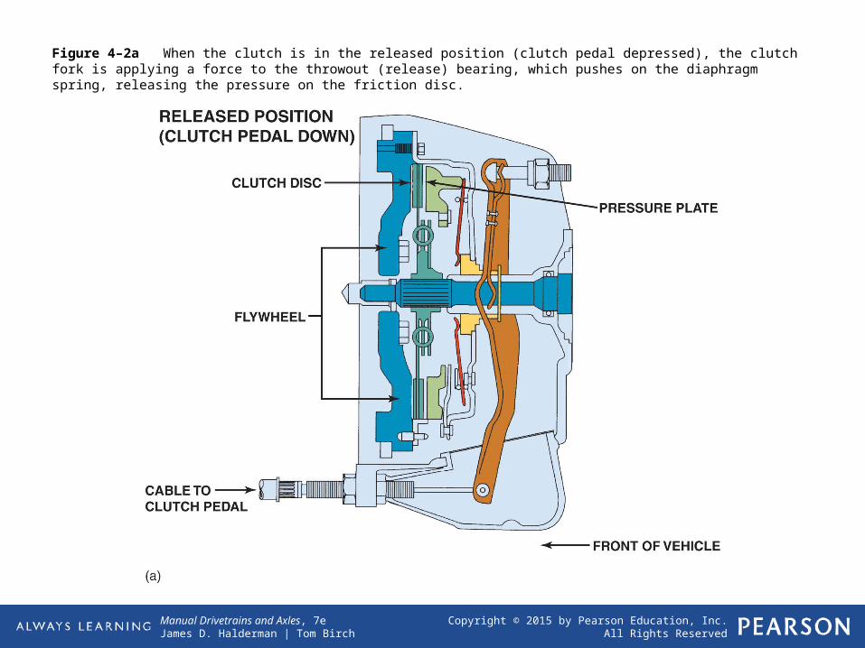
Figure 4–2a When the clutch is in the released position (clutch pedal depressed), the clutch fork is applying a force to the throwout (release) bearing, which pushes on the diaphragm spring, releasing the pressure on the friction disc.

Manual Drivetrains and Axles, 7eJames D. Halderman | Tom Birch

Copyright © 2015 by Pearson Education, Inc.All Rights Reserved

Figure 4–2b When the clutch is in the engaged position (clutch pedal up), the diaphragm spring exerts force on the clutch disc, holding it between the flywheel and the pressure plate.

Manual Drivetrains and Axles, 7eJames D. Halderman | Tom Birch

Copyright © 2015 by Pearson Education, Inc.All Rights Reserved

Figure 4–3 A replacement clutch is designed to meet the same friction specifications of the original so the new clutch will operate like new.

Manual Drivetrains and Axles, 7eJames D. Halderman | Tom Birch

Copyright © 2015 by Pearson Education, Inc.All Rights Reserved

Figure 4–4 A typical stock clutch friction disc that uses coil spring torsional dampers.

Manual Drivetrains and Axles, 7eJames D. Halderman | Tom Birch

Copyright © 2015 by Pearson Education, Inc.All Rights Reserved

Figure 4–5 A marcel is a wavy spring that is placed between the two friction surfaces to cushion the clutch engagement.

Manual Drivetrains and Axles, 7eJames D. Halderman | Tom Birch

Copyright © 2015 by Pearson Education, Inc.All Rights Reserved

Figure 4–6 A racing or high-performance clutch disc lacks the features of a stock clutch disc that help provide smooth engagement.

Manual Drivetrains and Axles, 7eJames D. Halderman | Tom Birch

Copyright © 2015 by Pearson Education, Inc.All Rights Reserved

Figure 4–7 A coil spring (lever style) clutch pressure plate.

Manual Drivetrains and Axles, 7eJames D. Halderman | Tom Birch

Copyright © 2015 by Pearson Education, Inc.All Rights Reserved

Figure 4–8 Typical diaphragm-style pressure plate that uses a Belleville spring.

Manual Drivetrains and Axles, 7eJames D. Halderman | Tom Birch

Copyright © 2015 by Pearson Education, Inc.All Rights Reserved

Tech TipUse a “Bent Finger” Pressure Plate

Centrifugal force can affect a diaphragm clutch.During a very high RPM disengagement, the fingers

can be moved far enough forward by centrifugalforce so that they pass over center (beyond flat).

Some people have experienced this during a shift athigh RPM when the pedal stays on the floor while the

engine overrevs. To prevent this, “bent finger” diaphragms

are used for installations where high RPMshifts might occur. The shape of the fingers keeps

them from traveling over center. ● SEE FIGURE 4–9.

Manual Drivetrains and Axles, 7eJames D. Halderman | Tom Birch

Copyright © 2015 by Pearson Education, Inc.All Rights Reserved

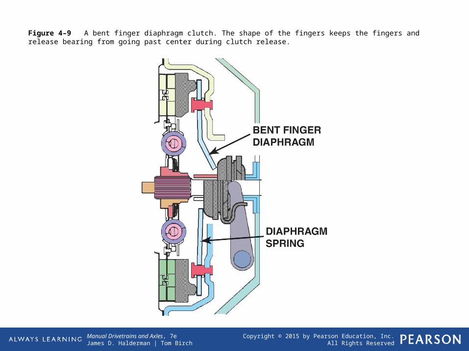
Figure 4–9 A bent finger diaphragm clutch. The shape of the fingers keeps the fingers and release bearing from going past center during clutch release.

Manual Drivetrains and Axles, 7eJames D. Halderman | Tom Birch

Copyright © 2015 by Pearson Education, Inc.All Rights Reserved

Figure 4–10 A double disc clutch that uses a floater plate between the two discs. The second disc doubles the clutch torque capacity.

Manual Drivetrains and Axles, 7eJames D. Halderman | Tom Birch

Copyright © 2015 by Pearson Education, Inc.All Rights Reserved

Figure 4–11 The ring gear, which is attached to the outer rim of the flywheel, provides the teeth needed to mesh with the starter pinion gear.

Manual Drivetrains and Axles, 7eJames D. Halderman | Tom Birch

Copyright © 2015 by Pearson Education, Inc.All Rights Reserved

Figure 4–12 A flywheel being machined (ground) to provide the correct surface finish for the replacement clutch disc.

Manual Drivetrains and Axles, 7eJames D. Halderman | Tom Birch

Copyright © 2015 by Pearson Education, Inc.All Rights Reserved

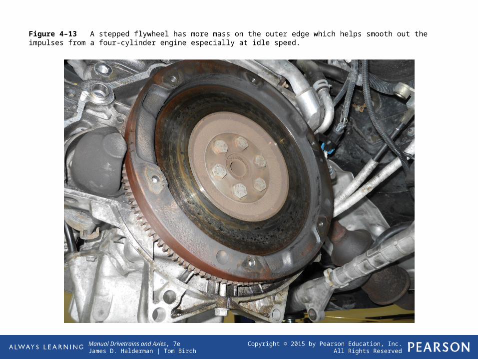
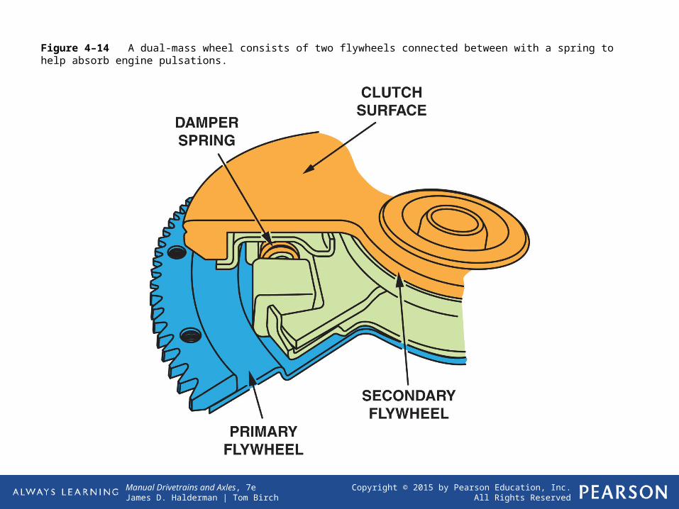
Figure 4–13 A stepped flywheel has more mass on the outer edge which helps smooth out the impulses from a four-cylinder engine especially at idle speed.

Manual Drivetrains and Axles, 7eJames D. Halderman | Tom Birch

Copyright © 2015 by Pearson Education, Inc.All Rights Reserved

Figure 4–14 A dual-mass wheel consists of two flywheels connected between with a spring to help absorb engine pulsations.

Manual Drivetrains and Axles, 7eJames D. Halderman | Tom Birch

Copyright © 2015 by Pearson Education, Inc.All Rights Reserved

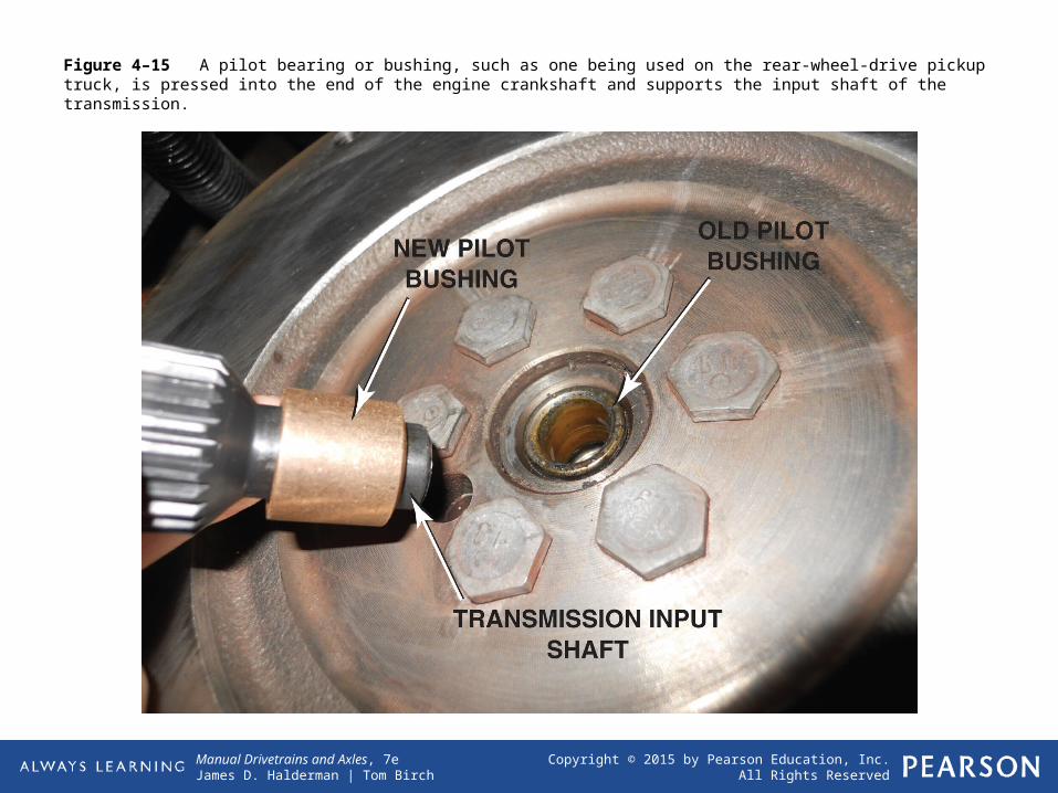
Figure 4–15 A pilot bearing or bushing, such as one being used on the rear-wheel-drive pickup truck, is pressed into the end of the engine crankshaft and supports the input shaft of the transmission.

Manual Drivetrains and Axles, 7eJames D. Halderman | Tom Birch

Copyright © 2015 by Pearson Education, Inc.All Rights Reserved

Figure 4–16 Pilot bearings (bushings) are made in several different designs depending on the application.

Manual Drivetrains and Axles, 7eJames D. Halderman | Tom Birch

Copyright © 2015 by Pearson Education, Inc.All Rights Reserved

Figure 4–17 A typical cable clutch linkage uses a cable to transmit motion from the pedal to the release bearing.

Manual Drivetrains and Axles, 7eJames D. Halderman | Tom Birch

Copyright © 2015 by Pearson Education, Inc.All Rights Reserved

Figure 4–18 Simple hydraulic clutch system. The hydraulic fluid will transmit force and motion from the clutch pedal to the slave cylinder.

Manual Drivetrains and Axles, 7eJames D. Halderman | Tom Birch

Copyright © 2015 by Pearson Education, Inc.All Rights Reserved

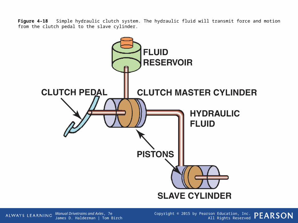
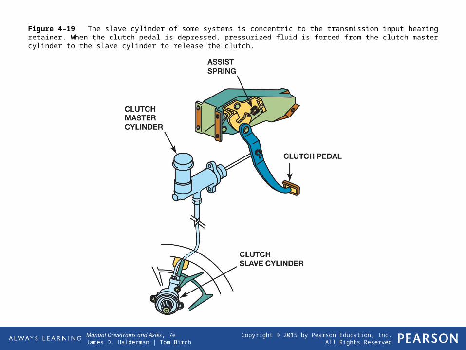
Figure 4–19 The slave cylinder of some systems is concentric to the transmission input bearing retainer. When the clutch pedal is depressed, pressurized fluid is forced from the clutch master cylinder to the slave cylinder to release the clutch.

Manual Drivetrains and Axles, 7eJames D. Halderman | Tom Birch

Copyright © 2015 by Pearson Education, Inc.All Rights Reserved

Figure 4–20a A release (throwout) bearing on a transmission that uses a clutch fork and a mechanical or cable-operated linkage.

Manual Drivetrains and Axles, 7eJames D. Halderman | Tom Birch

Copyright © 2015 by Pearson Education, Inc.All Rights Reserved

Figure 4–20b A style of release bearing that includes the slave cylinder, sometimes called a concentric slave cylinder.

Manual Drivetrains and Axles, 7eJames D. Halderman | Tom Birch

Copyright © 2015 by Pearson Education, Inc.All Rights Reserved

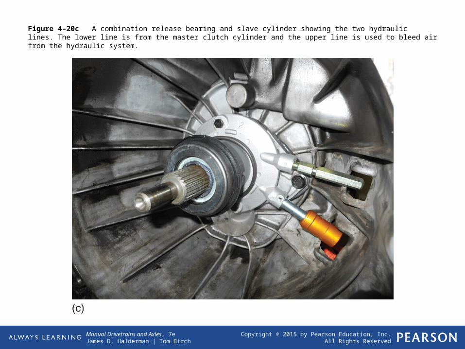
Figure 4–20c A combination release bearing and slave cylinder showing the two hydraulic lines. The lower line is from the master clutch cylinder and the upper line is used to bleed air from the hydraulic system.

Manual Drivetrains and Axles, 7eJames D. Halderman | Tom Birch

Copyright © 2015 by Pearson Education, Inc.All Rights Reserved

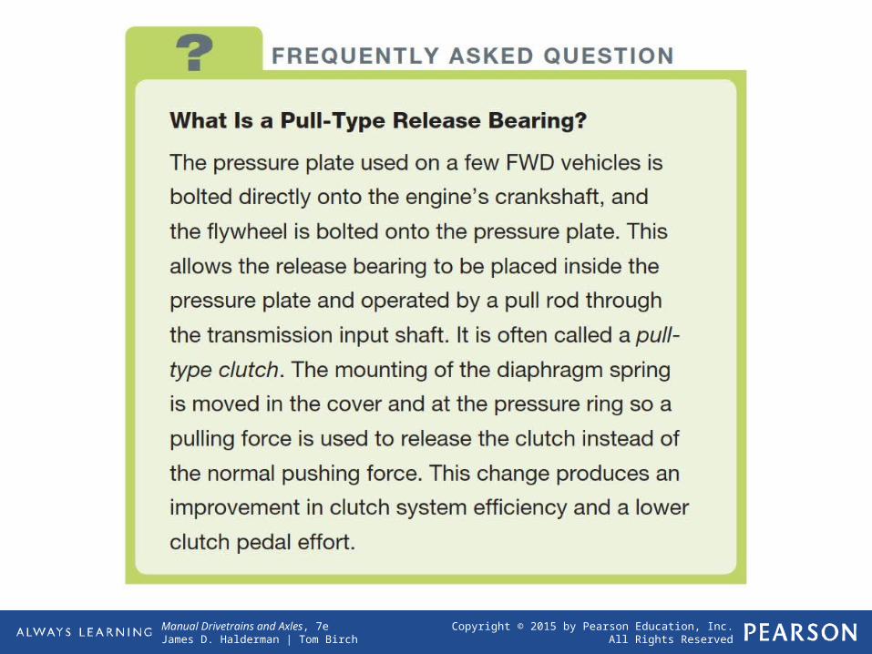
Frequently Asked QuestionWhat Is a Pull-Type Release Bearing?

The pressure plate used on a few FWD vehicles is bolted directly onto the engine’s crankshaft, and the flywheel is bolted onto the pressure plate. This allows the release bearing to be placed inside the pressure

plate and operated by a pull rod through the transmission input shaft. It is often called a pulltype

clutch. The mounting of the diaphragm spring is moved in the cover and at the pressure ring so a

pulling force is used to release the clutch instead of the normal pushing force. This change produces an

improvement in clutch system efficiency and a lower clutch pedal effort.

Manual Drivetrains and Axles, 7eJames D. Halderman | Tom Birch

Copyright © 2015 by Pearson Education, Inc.All Rights Reserved

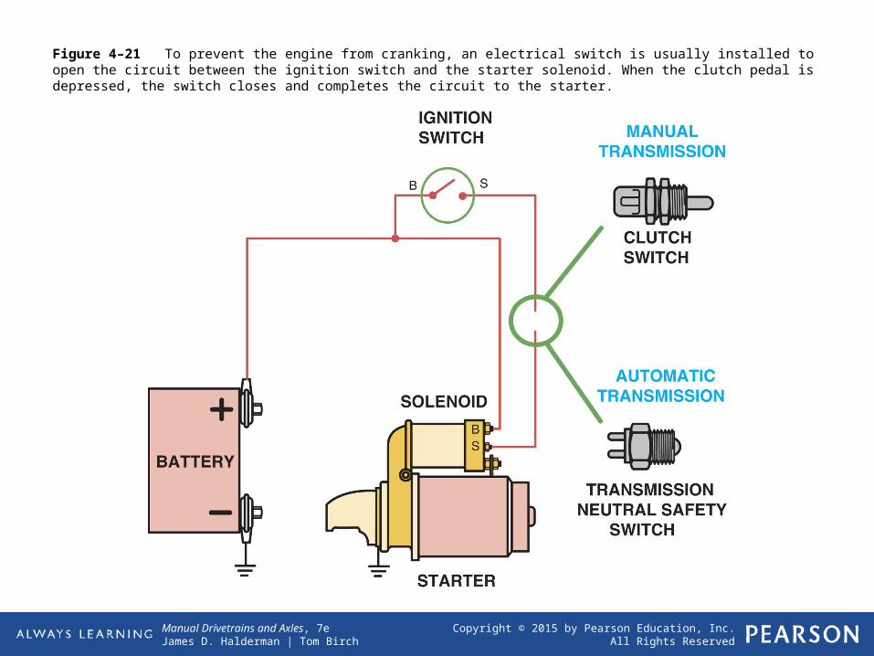
Figure 4–21 To prevent the engine from cranking, an electrical switch is usually installed to open the circuit between the ignition switch and the starter solenoid. When the clutch pedal is depressed, the switch closes and completes the circuit to the starter.


Recommended