72
w w w.environment-agency.gov.uk Manual for provision of upstream migration facilities for Eel and Elver Science Report SC020075/SR2

w w w.environment-agency.gov.uk
Manual for provision of upstream migration facilities for Eel and Elver
Science Report SC020075/SR2

Science Report Manual for Provision of Upstream Migration Facilities for Eel and Elverii
The Environment Agency is the leading public body protecting andimproving the environment in England and Wales.
It’s our job to make sure that air, land and water are looked after byeveryone in today’s society, so that tomorrow’s generations inherit acleaner, healthier world.
Our work includes tackling flooding and pollution incidents, reducingindustry’s impacts on the environment, cleaning up rivers, coastalwaters and contaminated land, and improving wildlife habitats.
PUBLISHED BY:Environment Agency, Rio House, Waterside Drive, Aztec West,Almondsbury, Bristol, BS32 4UDTel: 01454 624400 Fax: 01454 624409
ISBN: 1844323498
© Environment Agency December 2004
All rights reserved. This document may be reproduced with priorpermission of the Environment Agency.
This report is printed on Cyclus Print, a 100% recycled stock,which is 100% post consumer waste and is totally chlorine free.Water used is treated and in most cases returned to source inbetter condition than removed.
Further copies of this report are available from: EnvironmentAgency Customer Contact Centre Tel: 08708 506506
AUTHORS:David J.Solomon, Michael H.Beach
Dissemination Status:Internal: Released to RegionsExternal Public Domain
Statement of Use:This manual sets out design criteria for upstream passage facilitiesat obstructions for eels and elvers, based upon assessments of themigratory behaviour and ecology of Anguilla spp. It is intended foruse by fisheries managers with responsibility for or an interest in themanagement of stocks of eels and elvers. It is largely based uponthe R&D Technical Report W2-070/TR1 “Fish pass design for eeland elver (Anguilla anguilla)”.
Research Contractor:Dr David Solomon,Foundry Farm, Kiln Lane, Redlynch, Salisbury, Wiltshire, SP5 2HT,UKTel 01725 512523 email:- [email protected]
Environment Agency’s Project Manager:Miran Aprahamian, Warrington Office
Science Project Number:SC020075
Product Code:SCHO1204BIME-E-P

Science Report Manual for Provision of Upstream Migration Facilities for Eel and Elver iii
Science at the Environment Agency
Science underpins the work of the Environment Agency, by providing an up to dateunderstanding of the world about us, and helping us to develop monitoring toolsand techniques to manage our environment as efficiently as possible.
The work of the Science Group is a key ingredient in the partnership betweenresearch, policy and operations that enables the Agency to protect and restore ourenvironment.
The Environment Agency’s Science Group focuses on five main areas of activity:
• Setting the agenda: To identify the strategic science needs of the Agency toinform its advisory and regulatory roles.
• Sponsoring science: To fund people and projects in response to the needsidentified by the agenda setting.
• Managing science: To ensure that each project we fund is fit for purpose andthat it is executed according to international scientific standards.
• Carrying out science: To undertake the research itself, by those best placed todo it - either by in-house Agency scientists, or by contracting it out touniversities, research institutes or consultancies.
• Providing advice: To ensure that the knowledge, tools and techniquesgenerated by the science programme are taken up by relevant decision-makers,policy makers and operational staff.
Professor Mike Depledge Head of Science

Science Report Manual for Provision of Upstream Migration Facilities for Eel and Elveriv
CONTENTS
List of Tables vii
List of Figures vii
Executive Summary ix
1 Introduction 11.1 Background and terms of reference 11.2 Types of situation where passage facilities are required 1
2 Assessment and survey – essential first steps 3
2.1 Overall assessment of obstructions in a catchment context 32.2 Site surveys. 5
3 Fundamental approaches to providing facilities for eel passage 63.1 Fundamental design considerations 63.2 Six basic approaches 73.3 Facilities based on ramps with substrate 9
3.3.1 General description 93.4 Pipe passes 93.5 Lifts and locks 93.6 Facilities based on easements 103.7 Removal of the barrier 10
4 Biological criteria for design of passage facilities 114.1 Introduction 114.2 Season 114.3 River discharge 114.4 Size of fish to be catered for 114.5 Water temperature 124.6 Illumination 124.7 Water flow and eel swimming ability 124.8 Predation 134.9 Downstream migration 13
5 Detailed design considerations 15
5.1 Introduction 155.2 Siting of facilities 155.3 Facilities based on substrate ramps 15
5.3.1 Advantages and limitations of different types of installation 155.3.2 Natural substrates 155.3.3 Bristle and brush substrates 165.3.4 Other synthetic substrates 17

Science Report Manual for Provision of Upstream Migration Facilities for Eel and Elver v
5.3.5 Slope 205.3.6 Length of pass, and resting facilities 215.3.7 Width and depth 225.3.8 Flow down the pass 225.3.9 Changes in tailwater level 235.3.10 Changes in headwater level 235.3.11 Cover against light and predation 25
5.4 Facilities based on easement and “natural” channels 265.5 Pipe passes 265.6 Lifts and locks 275.7 Upstream outlet arrangements 285.8 Monitoring arrangements 285.9 Trap and transport 305.10 Eel passage through other fish passes 305.11 Attraction flow 325.12 Maintenance 335.13 Health and safety considerations 335.14 Protecting downstream migrants 33
6 Some installations analysed 356.1 General 356.2 Standard substrate passes 35
6.2.1 Moulin a Pigné, River Villaine, near Rennes, France 356.2.2 Pont-es-Omnès, River Frémur, near St Malo, France 366.2.3 Chadbury Weir, River Avon, England 37
6.3 Pumped-supply passes 386.3.1 Fort Halifax Dam, Maine, USA 386.3.2 Chambly Dam, River Richelieu, Quebec, Canada 39
6.4 Pass-traps 406.4.1 Rophemel Dam, River Rance, near St Malo, France 406.4.2 Greeneville Dam, Shetucket River, Connecticut 41
6.5 Eel lifts 426.5.1 Ville Hatte Dam, River Arguenon, France 42
6.6 Low cost and temporary installations 446.6.1 Explanation 446.6.2 Temporary installations; Thames, Darent, Severn and Avon 446.6.3 “Fish-Pass” prefabricated passes 456.6.4 “Portable passages”, Maine 456.6.5 Garrison Lake, Delaware 466.6.6 West Harbor Pond, Maine 47
7 Suggested designs for specific applications 487.1 General 487.2 Low-head structures with relatively stable headwater levels 487.3 Low-head structures with variable headwater levels 497.4 High-head structures 507.5 Constraints at gauging structures 507.6 Tidal barriers 517.7 Culverts 527.8 Facilities for installation of passes in the future 52

Science Report Manual for Provision of Upstream Migration Facilities for Eel and Elvervi
7.9 Requirements for further investigation 53
8 Suppliers 558.1 Introduction 558.2 “Fish-Pass”, France 558.3 Milieu Inc, Canada 558.4 Bristle substrate suppliers. 558.5 “Pelcar” and “Evergreen” concrete blocks (Section 5.3.4) 568.6 Enkamat geotextile 568.7 Akwadrain substrate 56
9 Acknowledgements 57
10 References 58

Science Report Manual for Provision of Upstream Migration Facilities for Eel and Elver vii
LIST OF TABLES
PageTable 5.1 Attributes of different types of substrate ramp eel passes 16
Table 5.2 Proportion of small eels using ramps with different substrates 17
Table 5.3 Length per unit head for ramps of different slopes 21
Table 5.4 Flow down a selection of passes 23
Table 5.5 Effective head range and corridor width of a ramp with different lateralslopes
24
Table 5.6 Stage height exceedence figures for three gauging stations in SouthernEngland
25
Table 5.7 Typical velocities in fish passes 31
LIST OF FIGURES
Page
Figure 3.1 The three basic types of substrate-ramp eel passes 8
Figure 3.2 The principle of the fish lift 10
Figure 5.1 Bristle substrate with nylon bristles fixed to a polypropylene sheet 16
Figure 5.2 Milieu “Eel-ladder” substrate for eels over 15 cm in length 18
Figure 5.3 Milieu experimental eel pass substrate, machined from solidpolyurethane foam.
18
Figure 5.4 Plastic eel pass substrate developed by “Fish-Pass” in France,currently under evaluation.
19
Figure 5.5 “Akwadrain” plastic substrate 19
Figure 5.6 “Pelcar” concrete substrate 19
Figure 6.1 Eel pass at Moulin a Pigné 35
Figure 6.2 Detail of eel pass at Moulin a Pigné 35
Figure 6.3 Upstream pass and trap-pass at Pont-es-Omnès 36
Figure 6.4 Eel pass at Chadbury 37
Figure 6.5 Flow to the baffle pass cutting across the top of the eel pass,Chadbury
37

Science Report Manual for Provision of Upstream Migration Facilities for Eel and Elverviii
Figure 6.6 Pumped-supply pass at Fort Halifax Dam. . 37
Figure 6.7 Eel pass at Chambly Dam. . 39
Figure 6.8 View of Chambly Dam eel pass from above. . 39
Figure 6.9 Rophemel Dam eel pass-trap. 41
Figure 6.10 Eel pass-trap at Greenville Dam. 42
Figure 6.11 Akwadrain substrate extending beyond the top of the ramp atGreenville Dam eel pass.
42
Figure 6.12 The Ville Hatte Dam eel lift. 43
Figure 6.13 Lift hopper at Ville Hatte Dam eel lift in lower position. 43
Figure 6.14 Pass-trap design from White and Knights (1994). 44
Figure 6.15 “Fish-Pass” prefabricated sluice-gate pass. 45
Figure 6.16 A “portable passage” being operated at Benton Falls Dam in Maine. 46
Figure 6.17 Elver pipe-pass at Garrison Lake, Delaware, soon after installation. 46
Figure 6.18 Garrison Lake elver pass two years after installation. 46
Figure 6.19 Vertical substrate board on the west ramp at West Harbor Pond. 47

Science Report Manual for Provision of Upstream Migration Facilities for Eel and Elver ix
EXECUTIVE SUMMARY
1. The overall aim of this study was to produce design criteria and best practicedesigns for eel and elver passes. A Technical Report (Solomon and Beach 2004)undertook a review of relevant aspects of eel biology and existing passagefacilities for eels and elvers. This manual summarises the earlier TechnicalReport and develops design criteria for passage facilities in a range of situations.
2. Types of obstruction where passage facilities might be required include tidalbarrages, tidal flaps, mill weirs, gauging weirs, amenity barrages and weirs,navigation weirs, dams for reservoirs or HEP, diversion dams or weirs, waterintake weirs and fish counting structures.
3. Essential first steps of catchment-wide and site specific surveys and evaluationare described and specified.
4. The manual describes fundamental approaches to providing upstream passagefacilities as an introduction to the analysis of existing installations. These arechannel passes, pass-traps, pumped-supply passes, pipe passes, lifts and locks,easements, and removal of the structure. The fundamental approaches toprotection of downstream migrants are also discussed.
5. Biological criteria for design of passage facilities are explored. These includethe seasonal timing of migration, effects of water temperature, river discharge,light, tide, lunar cycle and time of day on migratory activity, climbing ability,dispersion and rate of upstream migration, vulnerability to predation, sizes offish involved, and swimming ability.
6. Based upon the development of biological criteria, a series of detailed designconsiderations are presented. These include siting of facilities, facilities basedon substrates, facilities based on easements and “natural” channels, pipe passes,lifts and locks, upstream outlet arrangements, monitoring facilities, trap andtransport, passage of eels through passes designed for other species, attractionflows, maintenance, health and safety considerations, and protection ofdownstream migrants.
7. An analysis of a number of existing installations is presented, describing thefacilities and reviewing factors that aided design and installation, and good andlimiting features of design and installation.
8. A series of conceptual designs are presented for various situations includinglow-head and high head structures, gauging stations, tidal barriers and culverts.
9. Requirements for further investigation are identified.
10. A list is provided of suppliers of eel pass modules and materials used for theirconstruction

Science Report Manual for Provision of Upstream Migration Facilities for Eel and Elver
1
1 INTRODUCTION
1.1 Background and Terms of Reference
There is considerable concern regarding the status of the European eel, Anguillaanguilla, with recruitment falling throughout its range of distribution. In 2001 it wasestimated that recruitment had fallen by more than 90% since the early 1980s (Dekker2002). While it is likely that there are a number of factors contributing to this decline,including changes in the marine environment and a high level of exploitation, there isno doubt that production is restricted by eels being denied access to areas that theycould formerly colonise. Knights and White (1998) quote figures indicating that about7% (200,000 ha) of the stillwater habitat and 25% (68,000 ha) of the riverine habitat inEurope are inaccessible to eels due to man-made barriers.
The terms of reference for the project were as follows:-
1. To critically review published and unpublished literature on eel and elver passes,taking into account the issues of hydraulics, exit, entrance and approach,installation, robustness, maintenance and location.
2. To critically review the published and unpublished literature on the swimming speedof eel and elver and the factors affecting it.
3. To produce design criteria for eel and elver passes taking into account theirinstallation. Specific, as opposed to generic, designs may be needed for passessituated at gauging stations, at total exclusion tidal barrages and at tidal flaps.
4. To produce design criteria for traps, which can be incorporated into the fish pass.
5. To produce best practice design criteria and costs for the construction andinstallation of eel and elver passes and traps. Designs will need to ensure that theydo not compromise the function of the original structure, specifically passes at sitesused to measure flow.
The first four tasks were reported in the Technical Report W2-070/TR1 (Solomon andBeach, 2004). The aim of this document is to fulfil task 5, to produce a stand-aloneguidance note on design of passage facilities for eels and elvers. It draws heavily uponthe earlier Technical Report and summarises many of the findings of the whole study.
1.2 Types of Situation where Passage Facilities are Required
There are many types of man-made structure which can represent an obstruction, partialor complete, to the free upstream passage of elvers and eels. These include:-
Tidal barragesTidal flapsMill weirsGauging weirsAmenity barrages and weirsNavigation weirs

Science Report Manual for Provision of Upstream Migration Facilities for Eel and Elver
2
Dams for reservoirs and hydro-electric plantsDiversion dams or weirsWater intake weirsFish counting structuresCulverts
Early in the project it became apparent that the optimal design for any particularsituation was heavily site-specific, depending upon the function and form of thestructure concerned, the range of hydraulic conditions it experiences during the periodwhen passage is required, and its location in the watershed. For this reason it is notpossible to specify detailed designs to cover a range of sites; rather, the design has to betailored to each situation. That said, there are many generic principles and designs offacilities that can be adapted to specific situations. For this reason, the end product ofthis work is a series of design criteria and conceptual designs rather than detailed plansfor construction. The manual uses extensive examples of existing installations,considering critical design features and aspects of the individual installations that aresuccessful and, just as importantly, those that are less successful.

Science Report Manual for Provision of Upstream Migration Facilities for Eel and Elver
3
2 ASSESSMENT AND SURVEY – ESSENTIAL FIRST STEPS
2.1 Overall Assessment of Obstructions in a Catchment Context
The extent to which any particular structure represents an obstruction, and the potentialsolutions to allow passage, are highly site-dependent, and will vary with hydraulic headdrop, form of the structure, hydrodynamic conditions upstream and downstream,condition of the structure, and presence of edge effects which may represent conditionsmore benign for eel passage than the main flow. Many structures may represent anobstruction of varying severity depending on prevailing river flow and its associatedhydraulic conditions. Further, the impact of any particular obstruction on the eelpopulation within the catchment will depend upon the area and quality of potentialhabitat upstream, and on presence of further obstructions both upstream anddownstream. Addressing eel passage issues therefore involves step by step processes ofboth catchment-wide assessment and detailed survey of individual sites, followed byidentification of priority actions and detailed planning of individual facilities.
As discussed above, addressing problems for passage of eels and elvers is a whole-catchment process. For example, there will be less advantage providing access past astructure which opens up only a small area of habitat than one which gives access to alarge area. Similarly, there is little point in engineering potential passage if there areimpassable structures downstream – unless these downstream structures are also to beaddressed in the foreseeable future. It is therefore important that any programme ofinstallation of eel passage facilities is based on an overall catchment plan for thespecies. Such an approach has been taken by Evoy and Martin (2000) who assessedobstructions to eel and elver migrations in the rivers of the South part of the EnglishLake District. They classified all structures according to the level of problem theyrepresented:- 1 (no obstruction), 2 (slightly difficult), 3 (moderately difficult), 4 (verydifficult) and 5 (impassable). This allowed identification of the structures for priorityattention (construction of elver and eel passes) as well as a range of other actions.Steinbach (2003) undertook a similar exercise for the Loire catchment in France. Heused a very similar five-point scale (plus a category zero for obstacles that had beenremoved) to assess the level of obstruction represented by over a thousand structures inthis large catchment. Usefully, this latter publication included photographs of examplesof obstructions in each category.
Some smaller catchments may represent a simple issue, with a single obstructionperhaps at or near the tidal limit. In such cases it may be felt that little assessment isrequired, but even here decisions will need to be taken on priorities for action. Incontrast to migratory salmonids we are not dealing with individual river stocks, but asingle marine stock that enters many freshwater and brackish habitats to feed and grow.Thus it is likely to be more effective overall to give priority to addressing a problemstructure on another river if the potential area opened up represents a larger or moreproductive habitat.
While prioritising obstructions for attention based upon the perceived level of benefit isrecommended, it is most important that all opportunities are optimised whenever astructure is installed, repaired or modified. It is likely to be very much cheaper toundertake appropriate engineering for a future eel pass at such a time than to do soretrospectively. Thus even if the benefit of allowing passage or eels and elvers may be

Science Report Manual for Provision of Upstream Migration Facilities for Eel and Elver
4
limited, or if there are other barriers upstream or downstream that are currentlyimpassable, consideration should be given to incorporating eel passage facilities at anysite where work is being undertaken. This need not involve a full pass at this stage;provision of one or more channels into which an eel pass could later be installed willsuffice; these can be blocked off with stop logs or other means for the time being, andrepresent minimal cost. These comments apply equally to consideration of otherspecies of fish; indeed, all species present or likely to be present in the future should beconsidered when planning fish passage facilities at individual sites or on a catchmentbasis. It is therefore recommended that provision be made for later installation ofpassage facilities for all species whenever a structure is built, rebuilt, modified orrepaired, as long as this can be done at reasonable cost. Suggestions for appropriateengineering are made later in Section 7.8.
The first stage of the planning process is the catchment-wide assessment. This shouldbe map-based and should show all potential obstruction to free movement of eels andelvers, and other relevant environmental issues such as water quality problems. Ontothis should be added all available information regarding the distribution, abundance andsize structure of eel populations throughout the catchment. Such information can begathered from fish surveys (e.g. by electric fishing or netting), other biological surveys,fish-kill assessments, collections from intake screens, anglers catches, and commercialcatches (e.g. eel racks or fyke nets). In well-studied catchments it is likely that enoughinformation will be available to allow a good assessment of the dispersion of varioussizes of eel and identification of major obstructions to free access. In other situationssome further investigation might be required to complete the assessment. Electricfishing surveys below and above potential obstructions can be particularly useful in thisrespect. For example, Feunteun et al (1998) examined the situation throughout thecatchment of the River Frémur in France. They found mean populations of 0.66 eelsper m2 in the 400 metres downstream of obstructions, with less than one-third that levelin the 400 metres upstream – and in some cases, zero population upstream. Operation ofa temporary pass-trap at the appropriate time of year is also a sound approach; thiscould provide important information regarding the need for permanent facilities, thenumber and size range of eels needing passage, and the optimal location for the entrancefor the permanent installation.
The quantity and quality of the potential habitat upstream of the obstruction is alsolikely to affect prioritisation of sites for action and the cost-effectiveness of anyproposed action. It is the area of water and the type of habitat that will dictate thepotential productivity rather than the catchment area. In general, lowland areas withextensive drainage channels will be much more productive than steeply sloping uplandareas. Knights and White (1998) list the following criteria for ideal eel habitat:-
• Shallow and warm water, optimum 18-25oC, with more than 300 days per yearover 10oC
• Eutrophic (but not excessively dystrophic) conditions• Attached/emergent vegetation cover between 25 and 75%• High densities of benthic invertebrate prey
It would be useful to have a habitat assessment tool for eel populations, to provide atleast a semi-quantitative measure of the potential of the habitat represented by anyparticular drainage area. This is likely to have inputs based upon, inter alia, catchment

Science Report Manual for Provision of Upstream Migration Facilities for Eel and Elver
5
and wetted area, elevation, slope, seasonal temperatures, water chemistry and quality,vegetation and cover, distance from the sea, and overall biological productivity.Development of such a tool is beyond the scope of this study but it is recommended thatconsideration is given to addressing this as a separate study.
Once the catchment assessment has identified which obstructions are causing realtruncation of distribution it will be possible to prioritise those for prompt attention, andcommence surveying of individual sites.
2.2 Site Surveys
Before facilities for individual sites can be specified it is important that the site issurveyed and that the full range of hydraulic conditions that occur there are assessed.There are a number of examples of eel and elver passage facilities which are ineffectivebecause of wrong assumptions regarding such hydraulic conditions as headwater leveland tailwater level ranges during the period when elvers and eels are migrating, orwhere inadequate allowance was made for withstanding very high flows.
Information that should be gathered includes:-
• Range of river discharge during the season of operation proposed (Section 4.2)• Flow-frequency relationship during the operating season (exceedence
hydrograph)• Range of headwater levels and the relationship between headwater level and
discharge• Range of tailwater levels and the relationship between tailwater level and flow• Hydraulic head difference at various flows• Area where eels and elvers are known to gather, or are likely to gather, at
various flows (may require survey or temporary trap – Section 5.2)• Size range of eels present immediately below the obstruction, or likely to require
passage (Section 4.4)• Layout of the obstruction, which might suggest a particular approach to
provision of passage facilities• If available, engineering drawings showing appropriate detail of the structure
and upstream and downstream bed levels• Photographs of the structure
Once this survey is completed, consideration can be given to the design criteria forappropriate facilities.

Science Report Manual for Provision of Upstream Migration Facilities for Eel and Elver
6
3 FUNDAMENTAL APPROACHES TO PROVIDINGFACILITIES FOR EEL PASSAGE
3.1 Fundamental Design Considerations
The fundamental aim is to provide conditions to allow ascent of a hydraulic head drop,either natural or man-made, which is otherwise impassable either at all times or undersome conditions, or where ascent is otherwise difficult to the extent that recruitmentupstream is sub-optimal. Eels are incapable of jumping, and vertical falls of more thanabout 50% of their body-length represent a barrier to upstream migration (Knights andWhite 1998). Their swimming abilities are limited but they are adept at exploitingboundary layers and crawling over rough substrates; elvers are able to climb verticalwalls if the substrate is suitable (Section 4.7).
In most cases the following issues are relevant:
1. The fish must be able to locate the appropriate starting point for ascent e.g. thelower entrance of the pass. This may be achieved by constructing the entrancewhere the fish will naturally congregate, or by providing some attractionmechanism.
2. The fish must be able to enter the facility without undue effort and without causingundue stress.
3. The fish must be able to overcome the head difference within the facility withoutexpending undue effort. In practice this is often achieved by restricting the volumeof flow within the pass, restricting the velocity of flow within the pass, andproviding a substrate which both slows and disorganises the flow, and allows thefish to achieve a purchase with its body to allow the pass to be ascended by crawlingas much as swimming. This approach exploits the natural behaviour of the eel inseeking edge-effects and shallow water in its migrations, as well as its naturalclimbing behaviour. Another approach used particularly at sites with a highhydraulic head is to trap the fish at the base of the structure and carry them to thehead pond.
4. The fish leaving the pass should be deposited in an appropriate area for continuedupstream migration, for example where risk of being immediately washeddownstream can be minimised.
5. The facility should work under all conditions of head and tail water levels whichprevail during the period when fish are migrating at the site, or perhaps morerealistically, under conditions that prevail most frequently and for a major part ofthis time.
6. The fish should be protected from excessive predation at all points of the facilityincluding at the entrance, exit and within the pass.
7. Wherever possible, facilities for monitoring the effectiveness of the pass should beincorporated into the design, for example a trap or counter that can be operated onappropriate occasions. Such traps or counters could also be very useful inmonitoring recruitment on a wider scale, and for facilitating wider distribution of thetrapped fish to enhance recruitment.
8. Limited funding and other constraints may require that provision of facilities isprioritised, and that designs are cost-effective. It is likely that facilities which allow

Science Report Manual for Provision of Upstream Migration Facilities for Eel and Elver
7
passage of a limited size range of eels under restricted conditions will be very muchcheaper and less intrusive in visual and engineering terms than those that can allowpassage of all eels under all conditions. Such a facility is also greatly preferable tono passage facilities at all, which may be the only alternative where funding islimiting. Targeting the range of conditions under which eels wish to migrate at eachsite, and providing facilities appropriate for the size of eels at the site, are thereforeimportant. These issues are considered in Section 4.
9. Eel and elver passage facilities, especially those retro-fitted to existing structures,may be very vulnerable to damage by high flows and waterborne debris. Facilitiesshould therefore be designed with this in mind; possible approaches to avoidingsuch damage include robust construction, siting the facility where it is least exposedto adverse conditions, provision of protecting structures to divert flood flows andwaterborne debris, and removal of facilities during the winter. This last option mayalso facilitate maintenance.
10. Vandalism and theft of eels may be a problem at almost any site. Robustconstruction and locked covers may help, but a determined vandal may see suchfeatures as a challenge. Another approach is to site facilities where the generalpublic does not have access.
11. Human operator health and safety are fundamental concerns for all facilitiesrequiring maintenance, seasonal installation and removal, and especially monitoring.
12. Public safety and liability issues must also be addressed. For example, facilitiescould represent a danger to children playing nearby and it may be necessary torestrict access or at the very least provide adequate warning notices.
.3.2 Six Basic Approaches
There are six basic approaches to providing upstream passage:-
1. Construct a fish pass, which incorporates a channel that allows the fish to ascendunder controlled conditions that are within its capabilities. This commonly involvesthe use of ramps with a crawling or climbing substrate.
2. Trap the fish and release them above the obstruction. Again, this commonlyinvolves the use of a pass trap with ramps with crawling substrate.
3. Allow the fish to swim through the barrier e.g. through an orifice or pipe; thiswould normally require some mechanism for restricting water velocity through theaperture
4. Lift the fish either in a fish lock or a fish lift
5. Create conditions at the barrier to allow ascent, for example by roughening the backof a small weir or providing rocks to generate edge effects; in practice this approachmerges with 1 above.
6. Removal of the barrier.
Basic features of these approaches are now described; a detailed analysis of designfeatures forms Section 5.

Science Report Manual for Provision of Upstream Migration Facilities for Eel and Elver
8
Figure 3.1 The three basic types of substrate-ramp eel passes.

Science Report Manual for Provision of Upstream Migration Facilities for Eel and Elver
9
3.3 Facilities Based on Ramps with Substrate
3.3.1 General description
The basic aim of substrate channels or ramps is to provide a sloping waterway carryinga limited discharge, with a substrate to slow the water flow, to provide a purchase forthe elvers and eels to exercise their natural crawling and climbing ability, and in somecases to provide cover. Substrates may be natural materials, such as stone or vegetation,or artificial such as bristles or plastic mouldings.
There are three approaches to provision of such facilities (Figure 3.1):-
1. A standard channel pass built into or bypassing an obstruction, with the flow beingprovided directly by the level in the head pond. It is usual for the substrate to belaterally sloped so that part of it experiences the optimal level of submersion andflow over a range of upstream water levels.
2. A pass-trap, where the ramp does not ascend to the full retained height of theobstruction but instead the eels are retained in a trap box. The flow is usually agravity supply fed from the retained level in the head pond or by a pump from thetailrace. A range of pre-fabricated pass-traps is manufactured by “Fish-Pass” inFrance; several such installations are described in Section 6.
3. A pumped-supply pass, where the ramp ascends to a higher level than the fullheight of the obstruction; the ascending fish are then either retained in a trap or net,or return by gravity into the head pond.
For pass-traps and pumped-supply passes the substrate is usually not laterally sloped asthe flow down the ramp is controlled under all conditions.
3.4 Pipe Passes
Pipe passes comprise a pipe that passes through the barrier at some level below theretained water level, in theory creating a direct route of ascent. In practice the pipeusually passes through close to the retained level in order to minimise the velocity offlow through the pipe. A substrate is usually provided within the pipe, both to limitwater velocities and to allow the eels to crawl rather than having to swim. A majorlimitation of pipe passes is the tendency for the substrate to become blocked withdebris, requiring removal of the substrate for maintenance. They are most practicable atthe outflow from a large impoundment, which acts as a sediment trap for debris so thatthe water entering the pipe is clear of material that might block the substrate.
3.5 Lifts and Locks
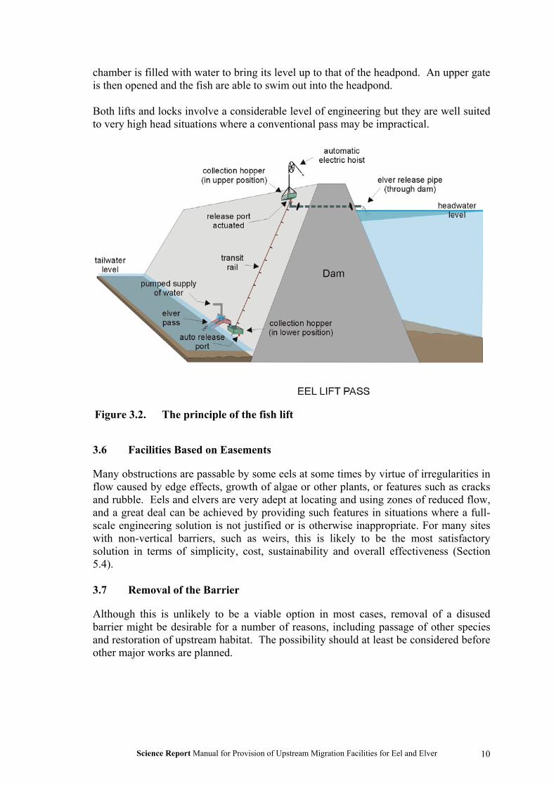
A fish lift comprises a chamber into which the fish are encouraged to swim or climb.Periodically, the chamber is lifted to or above the head-pond level, and the fish areallowed to swim from the chamber or are tipped or drained into the head pond(Figure 3.2).
Fish locks operate in the same manner as a navigation lock. The fish swim into the lockchamber when the lower gate is open. Periodically the lower gate closes and the
Science Report Manual for Provision of Upstream Migration Facilities for Eel and Elver
10
chamber is filled with water to bring its level up to that of the headpond. An upper gateis then opened and the fish are able to swim out into the headpond.
Both lifts and locks involve a considerable level of engineering but they are well suitedto very high head situations where a conventional pass may be impractical.
3.6 Facilities Based on Easements
Many obstructions are passable by some eels at some times by virtue of irregularities inflow caused by edge effects, growth of algae or other plants, or features such as cracksand rubble. Eels and elvers are very adept at locating and using zones of reduced flow,and a great deal can be achieved by providing such features in situations where a full-scale engineering solution is not justified or is otherwise inappropriate. For many siteswith non-vertical barriers, such as weirs, this is likely to be the most satisfactorysolution in terms of simplicity, cost, sustainability and overall effectiveness (Section5.4).
3.7 Removal of the Barrier
Although this is unlikely to be a viable option in most cases, removal of a disusedbarrier might be desirable for a number of reasons, including passage of other speciesand restoration of upstream habitat. The possibility should at least be considered beforeother major works are planned.
Figure 3.2. The principle of the fish lift

Science Report Manual for Provision of Upstream Migration Facilities for Eel and Elver
11
4 BIOLOGICAL CRITERIA FOR DESIGN OF PASSAGEFACILITIES
4.1 Introduction
The aim of this section is to consider aspects of the ecology and behaviour of eels thathave a bearing on the design and construction of facilities to provide passage pastobstructions. It represents a summary of the findings of the earlier phase of the project;Solomon and Beach (2004) provide full details.
4.2 Season
Virtually all upstream migration is observed within the six-month period April toSeptember inclusive. At or close to the tidal limit the period may be significantlyshorter than this, typically April to July inclusive. Facilities should therefore bedesigned with the flows prevailing during these months in mind. Where convenient,facilities can be withdrawn over the winter months for storage and maintenance, and toprevent damage by floods and ice.
4.3 River Discharge
Many passage facilities for eels and elvers will only operate effectively over a limitedrange of head and tailwater levels, and thus river flows. It is therefore criticallyimportant to match the flows and levels at which facilities will be effective to thoseprevailing when the fish wish to make use of them.
All available evidence indicates that elvers and eels migrate upstream either withoutregard to river flow, or migrate to a greater extent at low flows than at high flows. Aslow flows predominate during the migration season of April to September, becauseperiods of low flow may be of considerable duration in these months, and becauseperiods of high flow are usually of short duration during these months, facilities shouldbe designed to be effective at low flows. Clearly, the ideal would be to have facilitiesthat were effective at all flows, but this is likely to involve considerably greaterexpense. It is suggested that facilities that allow passage at lower flows whichpredominate for, say, only half of the April to September period, will be virtually aseffective at achieving optimal long-term dispersion as would facilities that werepassable at all flows. In this respect eel migration is rather different to that of migratorysalmonids. In the latter case movement at any point in a river system may be limited toa matter of days within the season, and any missed opportunity may result in a severetruncation of the spawning distribution and a greatly reduced level of resultantrecruitment. Eels, on the other hand, are likely to be able to maximise the opportunityto migrate over a period of several months, and the progress made on any particular day,in any particular month or even in any particular year is unlikely to be critical to thelong-term reproductive potential of the population.
4.4 Size of Fish to be Catered For
At or close to the tidal limit the upstream migration will be dominated by elvers (60 to90mm in length) and 1-group fish (90 to 130mm). However, numbers of fish up to300mm may also pass upstream at times, and facilities should cater for fish throughoutthe 60 to 300mm length range. In such situations however, the smaller fish should

Science Report Manual for Provision of Upstream Migration Facilities for Eel and Elver
12
always be the first priority, as the stock of the whole catchment is dependent upon them.Small eels are willing to climb vertical damp surfaces at times as long as there issufficient grip, but this activity appears to be restricted to fish of less than 100mm.
Further upstream, the range of sizes of fish that require passage shifts upwards. In mostUK situations elvers will not penetrate more than 15-25 km upstream of the tidal limitin their 0-group year, and 1-group fish will dominate with increased numbers of largerfish. In the Upper Severn and Thames, for example, there are few eels of less than 30cm in length and facilities to facilitate passage there should be designed with this higherlength range in mind. In upper reaches, passes installed for other species may wellprove to be adequate for the larger eels found there.
We are some way from being able to create a definitive model of the smallest andyoungest eels that occur at various points in a catchment. This is partly because thesituation appears to vary with the topography; for example the steeper River Dee showsa different pattern of distribution of ages of fish from the River Severn (Aprahamian1986, 1988). One approach to determining the size range of eels that might wish toeffect passage past a structure is to examine the population of fish occurring in the reachimmediately downstream. The danger then, of course, is that the size range may bedistorted by passage problems downstream, or by the hitherto impassability of thestructure under consideration. The safest approach may be to work from downstream toupstream, ensuring that each obstruction encountered is provided with appropriatefacilities for passage by eels of appropriate size. Within a year or so the eel populationdownstream of the next obstruction up river should reflect the size range of fishrequiring passage. With modular passes it may also be realistic to change the substratetype to a more appropriate one if the initial assessment proves to be mistaken.
4.5 Water Temperature
Water temperature affects the migratory behaviour and the swimming ability of the fish.Generally there is little activity below about 10oC, with increasing activity with risingtemperature up to well over 20oC. Small eels will climb damp surfaces if necessary butonly at higher temperatures, typically above 15oC.
4.6 Illumination
There are conflicting reports on the time of day of elver migration, probably reflectingdifferent local conditions. Passage is likely to be required night and day, so coversshould be provided in shallow-matrix passes to protect the fish from direct sunlight.Older eels migrate almost entirely at night. It is probably prudent to locate andconstruct passes so that artificial light does not shine directly upon them, or providecover to ensure darkness at all points during passage at night. Equally, this aversion tolight can be exploited for guiding downstream migrants to safe routes – see Section5.14.
4.7 Water Flow and Eel Swimming Ability
Many designs of pass for elvers and small eels involve some form of matrix in whichthe fish is in physical contact, and progress is made by crawling and climbing ratherthan by swimming. However, at some stage the fish has to swim in open water toapproach the pass or leave it at the top. Other facilities will depend on controlling the
Science Report Manual for Provision of Upstream Migration Facilities for Eel and Elver
13
current speed to a level that the fish requiring passage can swim against. Thus theswimming performance of eels and elvers is likely to be an issue for all upstreampassage facilities.
Observations on swimming performance, and climbing behaviour, of elvers and smalleels are described by Beach and Solomon (2004), derived from experimental studiesand the recently-developed “Swimit” model (Clough and Turnpenny 2001; Clough et al2002). For most purposes the burst speed (the speed that can be maintained for 20seconds) is probably the most appropriate design criterion to apply, as few situationswill require fast swimming to be maintained for longer than that; indeed, in somesituations, such as pool and traverse passes and deep slot passes, maximum velocitiesmay only be experienced for a few seconds at most. However, the possibility of periodsof fast swimming having to be maintained for longer than 20 seconds must beconsidered in baffle-type passes, where there are no opportunities for rest betweenentering and leaving the pass. For elvers of A. anguilla burst speeds are of the order of350 to 600 mm/sec, depending on body length. Burst-speeds for larger eels are of theorder of 1.15 m/sec for 200 mm fish, 1.25 m/sec for 400 mm fish, and 1.35 m/sec for600 mm fish.
The tendency for eels and elvers to be attracted to flowing water, and to gather at themost upstream point below obstructions, provides important pointers to the optimallocation of the downstream entrance to passage facilities, and for the provision of anattraction flow, as the volume of water flowing down the pass itself may be very small(Section 5.11).
At times, elvers and small eels (fish less than 10 cm) will climb wetted sloping or evenvertical surfaces, especially if they are covered with moss and algae. Although thisbehaviour is only apparent at temperatures above 15oC it has been exploited to providepassage facilities (see Section 6.6.6) and probably explains the presence of eelsupstream of barriers that otherwise appear well beyond the swimming capabilities ofsmall fish.
4.8 Predation
Predation is a major risk for elvers and small eels and they are likely to be particularlyvulnerable in passes, and as they approach and enter from downstream and leave theupstream exit. Shallow passes should be covered to prevent bird predation, guarded ateach end to prevent the entry of mammalian predators such as mink or rats, and provideadequate cover for fish dispersing from the upstream exit (Section 5.3.11).
4.9 Downstream Migration
The fundamental requirements for downstream passage facilities are quite different tothose for upstream migration. Most obstructions that an eel can overcome movingupstream will present little or no obstacle to downstream movement. A major problemcan occur, however, where a significant part of the flow is abstracted for water supplyor to drive machinery such as hydro-electric power (HEP) turbines, and where any eelsgoing with that part of the flow are likely to be killed or injured, or trapped in areservoir. For example, it has been calculated that up to 41% of silver eels migratingdown the River Meuse in Belgium and the Netherlands are killed by operation of HEP

Science Report Manual for Provision of Upstream Migration Facilities for Eel and Elver
14
plants (Vriese, 2002). The requirement is to prevent or discourage passage into theintake, and to guide the migrants to a safe bypass route. Approaches to this arediscussed further in Section 5.14. An alternative or additional approach of “shuttingdown” abstraction or generation at times of peak eel migration is discussed below.
The size of eels involved in the downstream migration of maturing fish range fromabout 280 mm to more than a metre. Based on rather few data for larger eels (Durif etal 2003), a fish of 280 mm would require gaps between screen bars of 15 mm or less toprevent passage.
Protection facilities would have to be effective in a wide range of flows including veryhigh discharges, though in many situations a high river flow would mean that theproportion being abstracted or passed through turbines under such conditions may beminor.
From the review described in the Technical Report (Solomon and Beach 2004) it isclear that any facilities for protection of downstream migrants would have to bedeployed from June to December inclusive to be fully effective. However, protection ofthe majority of migrants could be achieved by installation during the peak of the run,lasting about two months. The exact timing of the run peak is likely to vary somewhatbetween sites and between years, but September through November would appear tocover most fish.
The majority of migration past any particular point may take place during limited hourson relatively few nights, which could perhaps be fairly reliably identified, albeitsometimes at short notice, from information on lunar cycle, discharge, cloud cover etc.Movement is minimal during daylight. Haro et al (2003) estimated that, on average,half of the downstream run of eels on a small river in Maine occurred in a 30 day periodbetween September 10 and October 6. There may, therefore, be scope for a degree ofprotection to be afforded by closing down abstraction or electricity generation at nightfor limited periods of time. Several attempts to develop the predictive model requiredfor such an approach were reviewed by Rickhus and Dixon (2003); the best wasestimated to allow a reduction in mortality of about 50%. Oberwahrenbrock (1999)describes a preliminary model concept for such an early-warning system. Twoexamples of management based on this approach are recorded on the Shenandoah Riverin Virginia (Rickhus and Dixon 2003) and at Patea Dam in New Zealand (Chisnall et al,1999). Rickhus and Dixon (2003) suggest that this approach is more likely to beeffective on small river systems. A possibly significant advance is the development of abioassay system called MIGROMAT®, which detects the activity of a group of captiveeels held in a flow of river water (Anon 2002). The eels are fitted with short-rangetransmitters whose movement is monitored. Early results at a site on the Meuse in theNetherlands show that there is a clear correlation between activity of the captive eelsand migration activity in the river.
More investigation is needed regarding the depth at which silver eels travel, and optimaldesign and location of bypass facilities for them.

Science Report Manual for Provision of Upstream Migration Facilities for Eel and Elver
15
5 DETAILED DESIGN CONSIDERATIONS
5.1 Introduction
In this section detailed aspects of design for passes for eels and elvers are examined,and approaches to their provision are discussed. This is based largely on an analysis ofthe installations described in the Technical Report (Solomon and Beach 2004).
5.2 Siting of Facilities
The flow through most elver and eel passes is low compared to that flowing over theobstruction that they are designed to overcome. The siting of the downstream entranceis therefore a critical design consideration. The siting of the upstream exit of the pass isalso important to prevent the eels being carried back over the obstruction with the flow,but this is discussed later in section 5.7.
The obvious location for the entrance of the pass is wherever the fish tend to gather atthe foot of the obstruction. This can often be determined by observation, or from firstprinciples; close to banks or walls, and quiet corners at the most upstream point belowthe obstruction are obvious candidates. It may be prudent to employ a temporaryportable trap (see Section 6.6) to establish the optimal entrance location. It may be thateels gather in more than one location below a weir, for example close to each bank.This may require more than one pass, or more than one entrance to a single pass. Theoptimal entrance location may be within a very small area; Solomon and Beach (2004)describe a situation where elvers were gathering in large numbers between the entranceof a ramp pass and the face of the weir, a distance of the order of a metre or two.Provision of alternative facilities with access close to the weir face solved this problem(see section 6.6.6.).
5.3 Facilities Based on Substrate Ramps
5.3.1 Advantages and limitations of different types of installation
The advantages and limitations of the three types of substrate ramp facilities (as definedin Section 3.3) are listed in Table 5.1.
Many different substrates have been deployed, including natural materials, brushes,geotextile matting, rigidly mounted plastic shapes, and concrete mouldings. These aredescribed in the following sections.
5.3.2 Natural substrates
A number of natural substrates have been used in eel passes in the past. These includesmall tree branches or brushwood, heather, straw and hay (loose or twined into ropes orbraids), stones, and wood shavings. However, the review by Solomon and Beach(2004) concluded that substrates of natural materials (with the exception of stones incertain circumstances) are of historic interest only and have no place in modern passesfor eels and elvers. This conclusion does not, of course, apply to natural emergentvegetation which can represent an important aspect of passage based on easement(Section 5.4).

Science Report Manual for Provision of Upstream Migration Facilities for Eel and Elver
16
Table 5.1. Attributes of different types of substrate-ramp eel pass (see Figure 3.1)
Standard pass Pass-trap Pumped supply passAdvantages No separate
water supplyneeded.Resistant toflood damage.Lowmaintenance.Low manpowerrequirements.
Pump generally not needed(gravity supply).Migrants are trapped formonitoring and distribution.Not vulnerable tofluctuations in headwaterlevel.May be removed out ofseason.May be re-located to findoptimal location.
Migrants may be trappedfor monitoring anddistribution, or justallowed to migrate into theheadpond.Not vulnerable to changesin headwater level.May be removed out ofseason.Possible to re-locate.
Limitations More complexto monitor andtrap migrants.Very vulnerableto fluctuationsin head-waterlevel.
Dedicated plumbingrequired.Frequent attention needed,high manpowerrequirements.May be vulnerable to flooddamage and vandalism.Prone to blockage of feedpipe inlet.
Pumped supply required,with dedicated plumbing.Regular attention needed(frequent if trapping),medium to high manpowerrequirements.May be vulnerable to flooddamage and vandalism.
5.3.3 Bristle and brush substrates
Tufts of bristles of various materials have been used to create substrates for eel passesfor many years; early references include O’Leary (1971) and Tesch (1977), who recordsthe use of brushes in an eel pass on the Elbe as early as 1964. These early installationsoften used broom-heads arranged in a suitable array, but nowadays brush mats are madespecifically for eel passes using a range of suitable materials, dimensions and spacingsfor the bristles according to the situation and size of eels to be catered for (Figure 5.1).Typical is the range of bristle mats marketed by the company “Fish Pass” in France.
Figure 5.1 Bristle substrate with nylon bristles fixed to a polypropylene sheet

Science Report Manual for Provision of Upstream Migration Facilities for Eel and Elver
17
These are typically 1000 mm by 400 mm polypropylene mats with clumps of bristlesabout 70 mm in length. Each clump comprises about 25 bristles. The spacing of thebristle clumps is varied according to the size of eels to be passed – either 14 or 21 mmminimum gap. These are used in installations both with and without a lateral slopewithin the ramp. Panels with mixed spacing are also available, with a zone of closer-spaced clumps up the centre of the panel and zones of wider spaced clumps to eachside; these are generally used only where there is no lateral slope within the ramp. Themats can be cut for fitting to particular pass configurations, and the current price from“Fish-Pass” is €131 per 1000 x 400 mm panel for all bristle spacings. For many sites inEngland mats have been fabricated to a specification produced by the National RiversAuthority. This specification was as follows:- backing boards black polypropylene, 9-10 mm thick, 1000 mm long, and 460 or 1000 mm wide; bristles 1 mm gauge greenpolyester in clusters to fill 5 mm holes, hand-drawn with stainless steel drawing wire orpunch-filled; bristle length 70 mm proud of board; bristle spacing 5 mm holes drilled at40 mm centres, staggered rows at 20 mm spacing (for eels over 150 mm) or at 25 mmcentres with 12.5 mm between staggered rows (for elvers and small eels). The currentcontact details for companies that provided quotes for supply of boards to thisspecification in 1994 are listed in Section 8. A number of installations using thesesubstrates are detailed by Solomon and Beach (2004), some of which are described inSection 6 below.
Legault (1991) investigated numbers of eels using three pass ramps with differentbristle-tuft spacing (7, 14 and 21 mm) at different slopes (15o, 30o and 45o). The resultswere somewhat inconclusive (Table 5.2).
Table 5.2 Proportion of small eels (mean length 223 mm) using ramps withdifferent bristle substrates at three different slopes.
Slope of rampsSpacing mm 15o 30o 45o
21 7.6% 35.5% 52.0%14 61% 52.3% 38.4%7 31.4% 12.2% 9.6%
Total 100.0% 100.0% 100.0%
Clearly the closest substrate spacing (7 mm) was less used than the wider-spaced onesby this size-range of eels, but the variation with slope defies simple explanation.Interestingly, the mean length of eels recorded at a fish lift at the same site during thesame period was 293 mm; clearly, at least one of the passage facilities was size-selective. The fast current speeds in the approach to the fish lift may have discouragedsmaller eels from entering, or larger eels may have been less inclined to enter the bristlesubstrates.
5.3.4 Other synthetic substrates
Many other synthetic substrates have been used for eel passes, including sacks sewntogether (Tesch, 1977), discarded trawl netting (Shotzberger and Strait 2002), nylon

Science Report Manual for Provision of Upstream Migration Facilities for Eel and Elver
18
garden netting and Astroturf (Knights and White 1998), artificial vegetation, trade name“Cassonia” (Eckersley 1982) and geotextile matting (e.g. Enkamat 7020, Dahl 1991;Enkamat 7220, Wippelhauser 2001; Tensar, Matthews et al 2001). Enkamat isdescribed by the manufacturer as “a dense three-dimensional permanent erosionprevention mat, made of thick polyamide filaments fused where they cross”.
Figure 5.2 Milieu “Eel-ladder” substrate for eels over 15 cm in length
Various thicknesses are available; type 7020and 7220 mentioned above are 20 mm thick.A limitation of geotextile matting is that thesize of eel that can pass through the matrix islimited; Matthews et al (2001) mentionlarger “bootlace” eels which passed theirfacility late in the season may becametangled in the mesh, and Dahl (1991) refersto larger eels becoming jammed in the Tensarmatting when it was used in pipes, and dyingthere. Voegtle and Larinier (2000)concluded that Enkamat was very“aggressive”, causing eels to loseconsiderable amounts of mucus. They alsofound it to be size selective, only allowingpassage of eels of less than 260 mm. Themain use of these substrates would thusappear to be at lower river sites where elversand small eels predominate.
In recent years some new synthetic substrateshave been developed, based upon round solidshapes fixed to a flat bed. These aredesigned for use without a lateral slope, inpumped-supply passes and pass-traps. One used extensively in North America is called“Eel-ladder” and has been developed by Milieu Inc of Quebec (Figure 5.2). In this casethe shapes are open-topped cylinders 50.8 mm in diameter placed in holes in the
Figure 5.3. Milieu experimental eelpass substrate, machined fromsolid polyurethane foam.

Science Report Manual for Provision of Upstream Migration Facilities for Eel and Elver
19
substrate bed so that the tops project by 101.6 mm. The material is provided inmoulded modular channel form so only needs a frame to support it. This substrate isdesigned for eels of 150 to 750 mm, so is best suited to passes some distance up river.This design has been used with great success in passes at Chambly Dam (Section 6.3.2)and Beauharnois both in Quebec, and a number of other sites in Canada (Solomon andBeach, 2004). Milieu Inc also manufacture a smaller version of this substrate, for elversand small eels up to 150 mm long. This has studs 25 mm in diameter within a
preformed channel 140 mm wide.
Milieu are experimenting with anadaptation of this smaller substrate,which is machined from a solid blockof polyurethane foam. A prototype forelvers and small eels is shown inFigure 5.3. The substrate is designedto be laid in an aluminium channel.Exploration of the need for, andoptions for, coating of the machinedmaterial is continuing.
Another solid plastic substrate,developed by “Fish-Pass” in France, isillustrated in Figure 5.4. It is made ofABS and is supplied in sheets whichare designed to be fixed to slopingweir cills. The shapes are dome-topped cylinders, 30 mm in height andwith 14 mm gaps. The shapeminimises blocking with debris. Theoptimal operating water depth withinthe substrate is 2-12 mm, and theoptimal slope is up to 35o. Thissubstrate is under evaluation at sites inFrance.
Several eel passes in North Americahave used a plastic substrate with thetrade-name of “Akwadrain”. This is aplastic moulding designed for verticaldrainage against underground walls orwalls built into banks. Details areshown in Figure 5.5. The mainadvantages of this material are thevery low cost, and its physicalflexibility which could allow it to bedraped over weir backs as a temporaryinstallation. The main limitation is itsdelicate construction; it requiresregular replacement in otherwisepermanent installations.
Figure 5.4 Plastic eel pass substratedeveloped by “Fish-Pass” in France,currently under evaluation.
Figure 5.5 “Akwadrain” plastic substrate
Figure 5.6 “Pelcar” concrete substrate

Science Report Manual for Provision of Upstream Migration Facilities for Eel and Elver
20
Experiments have been conducted in France using concrete block substrates, includingsome manufactured for car parks and walkways to allow grass to grow through.Antoine Legault (pers.comm.) is experimenting with one such called “Pelcar” (Figure5.6). Voegtle and Larinier (2000) examined the effectiveness of several concrete blocksubstrates, most made specially but also one car park block “Evergreen” (similar to the“Pelcar” slab), and compared their effectiveness with bristle substrates. Tests wereconducted at three gradients, 15, 30 and 45o. For most substrates the shallowest slopegave the best results, with the highest level of successful passage and the greatesttolerance to variation in headwater level. Most movement at this slope was byswimming rather than crawling, as long as there was an adequate depth of water (10-20mm). At steeper slopes most activity was by crawling, with smaller eels in particularfinding ascent more difficult. When crawling, the eel needs to derive support fromseveral points, so that the spacing of studs becomes size-specific. The most effectivelayout of studs was found to be a quincunx (the arrangement of five objects, four in asquare with the fifth in the centre, which is, incidentally, the pattern formed bystaggered rows of brush bristles described in the specification in Section 5.3.3). Forelvers, bristle substrates and a closely-spaced concrete stud substrate were the mosteffective, because of the level of support provided. For small eels (150 mm) these twosubstrates plus “Evergreen” gave the best results provided the depth of water wasrestricted (less than 20 mm at 15o, 10 mm at 30o, 5 mm at 45o). For larger eels, thebrush substrate and a larger concrete stud form were the least selective, particularly atthe steeper slopes. All substrates were tested also with a lateral slope of 30o, whichgave good results with the exception of “Evergreen” at higher gradients. The mainpotential use for concrete substrates is probably where their great inherent strength is anadvantage, such as sites subject to severe floods, vandalism or foot traffic such ascanoeists.
5.3.5 Slope
The longitudinal slope of ramps represents a compromise between ensuring restrictedwater velocities, thus making ascent possible and comfortable for the eels (whichsuggests a shallow slope), and limiting the length of the installation especially at siteswith large hydraulic heads (which requires a steep slope). It is likely that different typesof substrate have different optimal slope ranges.
After experimenting with slopes up to 20o, the pass at Moses-Saunders Dam was set at12o as being “flat enough not to inhibit movement, and steep enough to ensure that anadequate water depth and current were maintained in all sections of the ladder”(Eckersley, 1982); at that time, natural green willow cuttings were being used as asubstrate.
Legault (1993) suggests that the longitudinal slope for brush substrates should be notmore than 35o.
The Milieu “Eel-ladder” substrate described in Section 5.3.4 is designed to be installedat slopes of up to 55o. Chambly Dam (Section 6.3.2), which uses this substrate, has aslope of 52o for its main run (9.2 m in length). The much longer pass at BeauharnoisDam, using the same substrate, has a slope of 40o for its main section 31 m in length,and 45o for its final section of 2.4 m (Desrochers 2002).

Science Report Manual for Provision of Upstream Migration Facilities for Eel and Elver
21
Passes in Maine using Enkamat have ramps at various angles including 43o at FortHalifax (Section 6.3.1) and 47o at Benton Falls; each of these installations has passedover 200,000 elvers and small eels in a year (Wippelhauser 2002). Enkamat has alsobeen used successfully attached to vertical surfaces for passage of limited numbers ofelvers (Section 6.6.6).
5.3.6 Length of pass, and resting facilities
The length of the pass is determined by the height of the structure and the angle of theramp; the relationship for a range of slopes is indicated in Table 5.3.
Table 5.3 Length per unit head for ramps of different slopes.
Slope o Length (m) for 1m ofhead
10 5.815 3.920 2.930 2.035 1.745 1.4
Thus for the 35o maximum slope recommended for brush ramps by Legault (1993), thelength of the pass would be 1.7 times the head lift of the ramp. The head lift of theramp would be the same as the head of the weir in a simple pass installation, but a littlemore where a pumped water supply was used to allow the ramp to extend above theupstream water level to allow for level fluctuations (see section 4.4.9).
Resting places are often incorporated into long passes, especially at a change ofdirection; these are typically pools or tanks with sufficient volume to considerablyreduce the flow velocity, and are often fitted with substrate to provide further protectionfrom the flow. Although no investigations could be identified where the requirementfor, and effectiveness of, such provisions had been examined, it is recommended thatresting boxes are incorporated at each turn in long passes; they are cheap and simple toinclude, may simplify engineering and are likely to be helpful to the fish.
The greatest hydraulic heads overcome by ramp passes that could be identified were27 m at Cathaleen’s Fall on the Erne (Matthews et al 2001; McGrath 1957) and 25 m atMoses-Saunders Dam on the St Lawrence (Whitfield and Kolenosky 1978; McGrath etal 2003b). No information is available regarding the slope and length of the formerpass. The pass at Moses-Saunders has a greater head (29.3 m) than the dam as the passextends above the upstream water level to allow for headwater fluctuation and to allowtrapping. At a slope of 12o the pass is 156.4 m in length, the longest eel pass identifiedin this study. It incorporates eight resting boxes (dimensions not available), one at eachchange of direction i.e. at approximately 17 m intervals.
The Moses-Saunders pass has worked well, with the minimum time for ascentcalculated at 70 minutes. The pass at Cathaleen’s Fall did not work well and was

Science Report Manual for Provision of Upstream Migration Facilities for Eel and Elver
22
replaced with a trap; “although elver were recorded from the tops of the ladders, it islikely that the arduous climb resulted in significant losses” (Matthews et al, 2001). Itshould be noted that the fish at Cathaleen’s Fall were predominantly elvers and 1 groupeels, whereas those at Moses Saunders were several years older and thus considerablylarger, and probably demonstrated greater stamina.
The head (and thus length) of ramp pass-traps at the base of dams or weirs is generallymuch less than that of the dam itself. The lift needs to be enough to ensure that the trapcan operate at all tailwater levels, and low enough so that the trap can be fed by gravityfrom the headwater level. Other issues are the cost of making the trap with anunnecessarily high lift, and safe, easy access for operation and maintenance.
5.3.7 Width and depth
Most of the substrate ramp passes reviewed by Solomon and Beach (2004) had channelsbetween 300 and 700 mm in width. One design of temporary pass-traps used on anumber of rivers was only 100 mm wide (Naismith and Knights 1988, White andKnights 1994), and the pass at Sunbury Weir on the Thames is 1000 mm in width. It isclear that passes of only limited width have been observed to pass relatively largenumbers of fish. Most passes are probably operating well below their potential fishcapacity. The original single-channel pass at Moses Saunders Dam on the St Lawrence,which was only 300 mm wide, handled over a million sizeable eels per year apparentlywithout undue congestion (Whitfield and Kolenosky 1978; Liew 1982). However, twosubstrate ramps at a site in Maine, each 300 mm wide, were apparently overwhelmed bya run of elvers in excess of 550,000 (Solomon and Beach 2004). Presumably this waslargely a function of timing of the run, with very large numbers moving in a short time.
Most of the narrower ramps are in pass-traps where the flow of water down the pass isregulated and is independent of headwater level, and the substrate is not sloped laterally.Thus the whole width of the substrate is usable at all times. In such situations the depthof the channel may be relatively shallow, with 100-150 mm being typical. Most of thewider ramps are in passes where the substrate is laterally-sloped to allow for changes inheadwater level, and thus only a fraction of the substrate is usable at any time (Section5.3.10). Such channels are inevitably deeper, typically of the order of 300 to 500 mm.
It is therefore suggested that a ramp width of 300 to 450 mm and depth of 100 mm isadequate in most pass traps and pumped supply passes, where the substrate is notlaterally sloped. Where elvers predominate and occur only in moderate numbers anarrower ramp may suffice – for example the 150 mm wide elver substrate unitsproduced by Milieu Inc (Section 5.3.4). Where the substrate is installed with a lateralslope, a width of 400 to 1000 mm appears more suitable, or even more if it is necessaryto cater for a wide range of headwater levels, with channel depth being dictated by thelateral slope of the substrate bed.
5.3.8 Flow down the pass
Most substrate passes operate most effectively with a surprisingly small volume of flowdown the ramp. Here we are considering only the flow within the pass itself; the issueof attraction flow, to help eels and elvers to locate the pass, is discussed below inSection 5.11.

Science Report Manual for Provision of Upstream Migration Facilities for Eel and Elver
23
The flow supplied to a range of effective passes is shown in Table 5.4. These are allpumped-supply passes or pass traps, where the volume of flow is under control. Instandard passes, including those with laterally-sloped substrate panels, the volume offlow will be determined by the headwater level and is very variable.
These indicate a range of flows from 8.1 to 230 l per minute per metre width, with allbut one being less than 66 l per minute per m. Few measurements of water depth areavailable, but at the lower flow rates there is likely to be just a matter of a few mm ofwater across the bed of the pass. In a study of the effectiveness of different substrates atdifferent slopes (described in Section 5.3.4), Voegtle and Larinier (2000) noted thatrestricted water depth was necessary for most efficient passage of small eels, and thatthis became more critical at higher slopes; best results were obtained with less than 20mm depth at 15o, less than 10 mm at 30o, and less than 5 mm at 45o. Bristle substratesmanufactured by “Fish-Pass” give best results with 2 – 12 mm depth over the bed (A.Legault, pers. comm.).
Table 5.4. Flow down a selection of pumped-supply passes and pass-traps. Fulldetails in Solomon and Beach (2004).
Site Substrate Width Flow l/min l/min/mwidth
Moses-Saunders Cassonia 600 mm 138 230Chambly “Eel Pass” 550 mm 36 65.5Beauharnois (pass-trap) “Eel Pass” 550 mm 30 54.5Beauharnois (new pass) “Eel Pass” 550 mm 24 43.6Maine “portable passage” Enkamat 300 mm 10.2 34Fort Halifax Enkamat 600 mm 8 13.3Greenville Bristle 430 mm 3.5 - 7 8.1 - 16.3Westfield Akwadrain 500 mm 20 40
5.3.9 Changes in tailwater level
Changes in tailwater level are easily catered-for by extending the ramp down to andbeyond the lowest tailwater level that occurs at the site during low summer flows – thisis important, as many elvers and eels are likely to be migrating at such times. At highertailwater levels part of the ramp will be drowned out but this will not affectperformance. Although this is a somewhat obvious requirement, Solomon and Beach(2004) describe sites where the bottom end of the ramp was perched above the tailwaterlevel at low flows.
5.3.10 Changes in headwater level
Variation in headwater level is a more complex problem than variation in tailwaterlevel. The problem is effectively avoided in trap-passes and pumped-supply passes byhaving the flow down the ramps independent of headwater level (Section 3.2), but it is amajor issue for standard passes.

Science Report Manual for Provision of Upstream Migration Facilities for Eel and Elver
24
The issue is usually addressed by arranging a lateral slope to the bed of the ramp andthus to the substrate, so that it is progressively inundated by increasing water levels anda different part of the cross-section of the substrate mat is functional for eel passage. Inselecting the lateral gradient there is a pay-off between the overall head range overwhich the ramp will function, and the area that will be available for passage at anyparticular headwater level. At one extreme, that of no lateral slope, the whole width ofthe channel would be available for migration but only within a very narrow range ofheadwater levels. At the other extreme, that of a steep lateral slope, the operating head-range will be greatly increased, but the cross-section area of the ramp that representseffective migration conditions at any time will be considerably less. The situation for arange of lateral slopes for a substrate mat of 700mm wide is shown in Table 5.5; theassumptions made are stated in the caption.
In theory, completely submerged substrate mats ought to offer some possibilities formigration. However, in practice, once the water level rises more than a few cm abovethe base of the bristles the rate of flow increases markedly, the bristles tend to beflattened by the flow and conditions are unlikely to be suitable for migration of elversand small eels. Even if there is a small area of the cross-section that offers suitableconditions the small fish are very vulnerable to being swept back downstream if theyventure outside this zone. This is particularly critical at the top of the ramp, whereaccelerating flows into the ramp tend to cut across the substrate so that any elveremerging is likely to be entrained and deposited at the bottom of the pass. Thissituation is apparent in Figure 6.5. Potential solutions to this are discussed inSection 5.7.
Table 5.5 Effective head-range and effective corridor-width of a 700 mm widebristle ramp with 70 mm bristles at various lateral slopes. Theeffective head range is the range of water depths over which water ispresent at a depth of 7 mm or less over at least part of the mat. Theeffective corridor is the width of the channel where water is presentat a depth of 70 mm or less at any particular water height.
Angle oflateral slope
Effective headrange
Effectivecorridor width
Degrees mm mm0 70 70010 192 39820 309 19230 420 12240 520 8445 565 7050 606 5960 676 4170 728 25

Science Report Manual for Provision of Upstream Migration Facilities for Eel and Elver
25
An important consideration at this point concerns the range and frequency distributionof headwater levels that are likely to occur during the migration period. On lowlandrivers where the levels are closely regulated for navigation (e.g. Thames andWarwickshire Avon), headwater levels may remain within the operating range of passesfor the great majority of the time during the season. But what of less regulated rivers?To explore this, gauging station data was sought for three differing un-regulatedwatercourses in Southern England:-
• the River Asker, a small spate stream in Dorset (East Bridge Gauging Station)• the Hampshire Avon, a groundwater fed river (East Mills G.S.)• the Dorset Stour, a river with both surface fed and groundwater fed tributaries
(Throop G.S.)
Although the Agency uses a design criterion of allowing effective passage for 90% ofthe time for salmonids, as discussed in Section 4.3 the requirement for eels and elvers isless stringent. Allowing passage for the drier half of the period between April 1 andSeptember 30 is suggested as a realistic target. The ranges of headwater levels for 50%of the time (between Q100, lowest flow included in the series, and Q50, flow exceededfor 50% of the time in the series), and for 90% of the time (Q100 to Q10), are shown inTable 5.6. For example, the range of headwater levels under which an eel pass wouldhave to operate in order to be effective for the drier 50% of the time between April 1and September 30 are 38 mm for the Asker, 245 mm for the Stour, and 483 mm for theAvon. These figures, of course, apply only at these gauging station sites; the rangeswill be different where the channel is narrower or broader than at these locations, suchthat an increase in flow would not be associated with the same changes in level.However, they give a good indication of the likely situation on such rivers.
Table 5.6 Some stage height exceedence figures for the period April toSeptember for gauging stations on three rivers in Southern England.
Stage height or range of stage heights (mm)Flow or flow range Asker Stour AvonQ100 132 194 26Q95 143 357 333Q50 170 439 509Q10 233 598 720Q100 toQ10 101 404 694Q100 to Q50 38 245 483
5.3.11 Cover against light and predation
Elvers and eels are vulnerable to predation while they are in shallow water in a situationfrom which they cannot quickly escape, such as ascending a substrate ramp. Majorpredators include birds and rats. Many pass-traps and pumped-supply passes aretherefore fitted with covers to exclude or discourage such predators – the situation isless critical in standard passes with a lateral slope as the greater water flow provides andelement of protection, though it is suggested that it is still good practice to provide
Science Report Manual for Provision of Upstream Migration Facilities for Eel and Elver
26
covers. Most migration takes place under the cover of darkness, and if there is any localartificial lighting eels may be reluctant to enter the shallow water of a substrate ramp.Light-proof covers are therefore often used, especially at dams or urban installationswith extensive lighting. Further, in shallow channels covers can also prevent eels fromclimbing out of the channel; this is particularly important at installations where any fishleaving the channel are likely to be killed or damaged. Any covers fitted should beeasily and safely removed for cleaning and maintenance.
5.4 Facilities Based on Easement and “Natural” Channels
As already discussed, eels are very adept at exploiting edge effects and reduced currentspeeds in shallow water and around and amongst stones and blocks. A very soundapproach to making obstructions passable is to provide such conditions without theengineering requirement or cost of constructing a formal pass. Surprisingly, fewexamples were identified during this study. It was attempted at Cobham Mill Weir byroughening the weir back but has probably been unsuccessful due to the steepness of theweir back and other hydraulic features (Solomon and Beach, 2004). On weirs with arelatively shallow-sloping downstream face it may be possible just to build-up a rubbleramp by dumping material; the material will act like a substrate ramp, proving areas oflow flow, edge effects and crevices. Knights and White (1998) suggest optimalhole/crevice sizes of about 2 mm for “glass eels”, 4mm for fish of 15cm, and 7-15 mmfor 20-40 cm eels. The material will also encourage the growth of emergent vegetation,providing further diversity for migrating eels and elvers to exploit. This approach canalso be useful in making the approach to a ramp pass easier for elvers and small eels.
A further development is the construction of artificial channels with natural features,such as rocks, pools and riffles, to bypass obstructions. This approach to fish passagehas been applied to a wide range of species in Germany (Gebler 1998; FAO/DVWK2002), Austria (Eberstaller et al 1998; Mader et al 1998) and Denmark (Nielsen,undated). This development has been so successful that Nielsen (undated) states that“nowadays fish ladders are only built in Danish streams if no other solutions arepossible”. General guidance on this approach is given by Jungwirth et al (1998) andParasiewicz et al (1998). The UK lags behind much of Europe in this importantdevelopment and only one example could be identified in England or Wales; Trudgill etal (2003) briefly describe a successful development on the River Don in Yorkshirewhich has apparently allowed the passage of eels and salmon. It is stronglyrecommended that this approach is explored as an option wherever passage facilities foreels and other species is required.
5.5 Pipe Passes
Pipe passes have been used in a variety of situations with widely varying hydraulicheads, ranging from less than a metre (eg Section 6.6.5) to more than 65 m (Patea Dam,New Zealand; Clay 1995, Mitchell 1995). Typically pipes of the order of 100 to 200mm diameter are used (for example see Section 6.6.5). Substrates deployed haveincluded netting (Sections 6.6.5), bottle brushes (Clay 1995) and Enkamat (Dahl 1991;Pedersen 1999).
There are distinct advantages in keeping pipe runs and head losses within pipe passes assmall as possible, both in terms of costs and operating complications. The pass at

Science Report Manual for Provision of Upstream Migration Facilities for Eel and Elver
27
Garrison Lake, Delaware (Section 6.6.5) uses an open channel approach to bring theelvers close to the crest of the dam, with only a short pipe through the crest itself(Shotzberger and Strait, 2002; Solomon and Beach, 2004). Limitations of a pipe passon the River Roding are discussed by Solomon and Beach (2004) and includesusceptibility to blockage, fixed nature of entrance in a tidal situation, and virtual lackof effective monitoring provision.
The 240 m long pipe pass at the 68 m high Patea Dam, New Zealand (Clay 1995;Mitchell 1995) is not a pipe pass in the same sense as that on the Roding, as the flow iscarefully controlled so that only a small trickle of water flows down the pipe. In thisrespect the pipe is really acting as a substrate ramp with a cover, and would appear tooffer little advantage over an open-channel arrangement with removable covers.Problems have arisen with high temperatures due to solar heating killing elvers withinthe pipe; it was estimated that it was taking elvers two nights and a day to ascend thepipe, leaving them vulnerable to high daytime temperatures, even though they wereonly moving by night in the nearby stream. The problem was addressed by shading thepipe from direct sunlight. The original bottle-brush substrate has now been replacedwith aggregate which is bonded to the base of the pipe with epoxy adhesive; this hasreduced maintenance and allows passage of a range of other species including the nativeGalaxias.
Pipe passes would appear to offer no advantage over open-channel designs wheredeployment of the latter is feasible, and considerable complications in terms ofmaintenance. Their use is not recommended where a substrate ramp is a viable andcost-effective alternative.
5.6 Lifts and Locks
Only two eel lifts were identified in the site survey undertaken for the Technical Report(Solomon and Beach, 2004), both in France. They were of similar design, and the laterone took into account the operating problems experienced at the first, whosedeployment has now been suspended. The main problem concerned the “leaky” natureof the hopper, which allowed numbers of small eels to escape during the haulingprocess. Both lifts use a bristle-substrate ramp to lift the eels through a short hydraulichead to fall into the hopper in its “collect” position; this overcomes any problemsassociated with variable tailwater level. The hopper is raised once per day. During thelifting cycle (taking a matter of several minutes) any eels ascending the ramp will bereturned to the tailwater level, but by arranging for the lift to be undertaken duringdaylight such activity should be minimal.
The main limitation of a lift system is cost; the second installation in France cost of theorder of £60,000 in 1995. Their use is likely to be restricted to high-head sites wheretheir installation is considered to be part of the environmental mitigation package at thetime of construction of the dam.
No fish lock systems specifically for eels were identified during the study, but Murphy(1951) commented that eels were seen using the Borland fish lock at Leixlip on theRiver Liffey in Ireland.

Science Report Manual for Provision of Upstream Migration Facilities for Eel and Elver
28
5.7 Upstream Outlet Arrangements
The design of the upstream exit of passage facilities is important, as the fish may bevulnerable both to predation and to being carried back downstream as they emerge fromthe pass. In some of the passes inspected, conditions at the point where elvers and eelsleave the upstream extent of the installation were such that re-entrainment with thedownstream flow appeared very likely (for example see Section 6.2.3).
With pass traps this is not really an issue, as the captured eels may be released at a siteof the operators choice – though selection of this location may be restricted by logisticconstraints. An interesting study has been conducted at Beauharnois Dam on the StLawrence River in Canada. Marking studies at this and other sites indicated that manyeels pass upstream through the pass more than once, apparently having been carriedback downstream through the turbines following the initial ascent. A study wastherefore undertaken to establish the optimal release location for planning futureinstallations (McGrath et al, 2003b). The rate at which tagged eels were recorded belowthe dam after release upstream indicated that they were vulnerable to being returneddownstream from release points some distance upstream, and that this was significantlysite-dependent. Using a mark and recapture approach it was found that eels releasedless than 295 m upstream of the dam showed a rate of return to the tailrace of about50%, while those released further away showed a return rate of less than 7%.Subsequent experiments with a long release pipe with shallow gradient indicated that itwas not practical to flush the eels through with a flow, as they tended to swim againstthe current. A much better result was obtained using a gentle flow in the oppositedirection, such that the eels had to swim against the current to emerge at the upstreamend of the pipe (K. McGrath, pers. comm.). It is stressed that these observations weremade at run-of-river hydroelectric plant; in situations where the downstream flowpasses over the top of a long-crested weir, release a short distance upstream is much lesslikely to be associated with eels returning downstream.
For pumped-supply passes and lifts, a steep discharge pipe from the top of the facilitycan be routed to an appropriate release point.
For standard passes the situation is often more critical, as the fish are usually dischargedclose to the accelerating downstream flow. Re-entrainment can be reduced byproviding a refuge for emerging fish in the form of deeper water and/or by extendingthe climbing substrate down into the headpond, and by installing a wall between the topof the eel pass and other downstream flow for some distance upstream. This wallshould extend from the riverbed to above the surface to allow the emerging fish toreturn safely to deeper water.
5.8 Monitoring Arrangements
Monitoring arrangements are of considerable importance for several reasons. First, theyprovide input into the assessment of the effectiveness of the installation, which mayassist modifications to the structure and operation of the pass and provide designinformation for other installations. Second, they can provide input for the urgentlyrequired overview of eel stocks and recruitment levels, particularly against the backdropof widespread falling recruitment. Third, if the fish are actually trapped, they can be

Science Report Manual for Provision of Upstream Migration Facilities for Eel and Elver
29
measured and any samples taken for biological purposes. Fourth, trapping also allowsthe option of re-distribution of stock upstream or elsewhere (Section 5.9).
The most usual approach to monitoring is through direct trapping of the elvers and eelsusing the pass. This happens de facto in trap passes, and is easily arranged in pumpedsupply passes. Fitting a trap to a standard pass or pipe pass is a little more complex butby no means impossible.
Surprisingly little attention appears to have been paid to development of the optimaldesigns for holding facilities within traps. Most installations merely store the capturedfish in a darkened box, or where numbers are limited, in a mesh net or sock. Eels arenaturally retiring animals when not actively migrating, seeking out cover among rocks,weeds and other structures. Provision of some sort of cover within the trap box wouldappear to be a sound idea, to prevent the retained animals from continuously trying toescape and exhausting themselves. This may be particularly important where theperiods between emptying the trap may be protracted, or where numbers of migratingeels are large. Further experimental investigation of optimal designs is required; oneapproach might be to provide a matrix of lengths of plastic pipe of appropriatedimensions for the eels being caught at the site; when processing the catch, the matrixcould be lifted from the trap box to extract the eels.
Trap design will be highly dependent upon site-specific considerations but some generalconsiderations apply. These include:-
1. The trap must be large enough to hold all elvers and eels that could build upbetween operator visits. This may involve some level of trial and error as themagnitude and timing of peaks of activity may be difficult to predict.
2. The trap should provide safe refuges for the animals collecting there (see above).Sacking bags and brightly-lit boxes without refuges, from which the animals areconstantly trying to escape, are not satisfactory.
3. The design should allow for the easy and safe removal and transfer of the trappedanimals (in this context “safe” refers to both the eels and the operator).
4. The trap should be protected from excessive temperatures that might be caused bydirect solar radiation, by placing in natural shade or by provision of shading.
Another approach to monitoring is automatic counting. Both resistivity and photocellcounters have been deployed on the pumped-supply pass at Chambly in Quebec(Section 4.4.2). Both worked well, and gave counts within 2% of the true numberassessed by a manual count. However, the run of eels at this site is of the order ofthousands per year of fish averaging 30 cm or so in length. These are readily detectedobjects generally well separated in time and space; obtaining a reliable count of elvers,which are small, may occur in vast numbers and are not well separated in time andspace is altogether a more daunting prospect. Travade and Larinier (2002) show aphotograph of a four-tube resistivity counter attached to the outlet from a pass-trap, butgive no further details. No automatic elver counting facilities appear to have beendeveloped to date.
Lastly, some idea of the effectiveness of a facility may be obtainable by observation,such as eels actually seen within the pass, a reduction in numbers downstream of the

Science Report Manual for Provision of Upstream Migration Facilities for Eel and Elver
30
pass, and an increase in numbers upstream of the pass. Although by no meansquantitative, such casual observations may be all that is practicable at some sites.
5.9 Trap and Transport
Trapping of elvers and eels at an obstruction low down on the river system offers theopportunity for constructive distribution of releases upstream. This may preclude theneed for passage facilities at other obstructions upstream, and may allow optimaldispersion to be achieved. It may also avoid heavy predation, which may occur wherepredators may learn that the exit from a pass is a productive feeding ground. Thisapproach may be particularly useful at the start of a strategic passage improvementprogramme.
The principles and practice of such distribution are beyond the scope of this report butMatthews et al (2001) describe such activities on the Erne using elvers trapped atCathaleen’s Fall and Cliff. The elvers are released at 30 to 50 sites throughout thecatchment, and the target-stocking rate is 1kg per hectare per year.
5.10 Eel Passage Through Other Fish Passes
Existing fish passes may provide adequate facilities for eels in some situations. Fishlocks, fish lifts and natural type installations (rocky/vegetation-filled channel) may wellpass all sizes of eels. Adult eels are able to use some pool and traverse, vertical slot andbaffle-type fish passes if the conditions within them are within their swimming ability.This is likely to be of greatest relevance in the upper parts of larger catchments whereonly larger eels are present.
Armstrong (1994) records eels successfully passing upstream through a Larinier passwith a mean velocity of 1.3-1.4 m/sec, and Porcher (2002) reports visual evidence ofeels passing through fish passes fitted with observation windows. Travade et al (1998)report large numbers of 200-300 mm eels using a vertical slot fish pass at Bergerac onthe Dordogne River, with a head-loss of 300 mm between pools. However, few usedanother vertical slot pass at La Bazacle on the Garonne. Although the head-lossbetween pools was the same at Bergerac (300 mm) the pools were more turbulent (200W/m3 compared to 150 at Bergerac) and this was thought to be a factor.
The water velocities predicted in various types of fish pass are summarised in Table 5.7.The slopes and dimensions used in this table are generally those for passes suitable forsmaller species such as trout and coarse fish. A 600 mm eel should be able to maintaina burst speed of around 1.4 m/sec for 20 seconds (Section 4.7). An adult eel of this sizeshould be capable of ascending Denil and Larinier passes of moderate length. Thesituation for pool and traverse and vertical slot passes is rather different, as the fish mayhave to swim at the maximum velocity in the pass (within the notch or slot) for onlyvery short periods - perhaps less than a second at each traverse. Also, eels are veryadept at exploiting boundary layers and zones of reduced flow so may be able to ascendpasses where the predicted velocities are greater than the accepted swimming ability ofthe fish.
For example, in the situation described above for a 300 mm head loss through a verticalslot at a pass at Bergerac, the mean velocity through the slot is predicted at 2.43 m/sec.

Science Report Manual for Provision of Upstream Migration Facilities for Eel and Elver
31
Table 5.7. Typical velocities in fish passes
Pass type Conditions Velocity (m/sec)1 NotePool and traverse 300 mm head between pools 2.43 2
Vertical slot 300 mm head between pools 2.43 3
Undershot sluice 600 mm head drop 3.43 4
Plane baffle Denil Not greater than 20% 1.05-1.40 5
Alaska steep Not greater than 25% 1.2 6
Larinier 15% slope, 350 mm headwaterdepth
1.3 7
Baulk ? 2.5 8
Notes on Table 5.7:
1 The velocity quoted here is the mean velocity across the smallest cross-section of the pass, e.g. within the notch of apool and traverse pass, or within or over the baffles of a baffle pass.
2 is a fish pass with a notched traverse with a maximum velocity dictated by the hydrometric head over the traverses.It can accommodate moderate variations in upstream and downstream water levels. The volume of the pools foradequate energy dispersion is related to hydrometric head and volume of flow.
3 is a fish pass with vertical slots almost the full depth of the inter-pool traverses. This fish pass can accommodatesignificant variations in upstream and downstream water level variations provided the overall head loss does notincrease too much. Energy dispersion is achieved by careful design of notches so that flow jets are directed toprovide energy absorption and more tranquil areas for fish to rest. This type of pass is designed mainly for higherflows and is more suitable for salmon (minimum notch width 300mm) but a narrower notch width (200mm) issuitable for trout and coarse fish.
4 is not a fish pass in the true sense but will afford passage if water velocities, which are dictated by hydrometrichead, are sufficiently low. It again requires ‘burst’ swimming for ascent with the added difficulty of restricted accessif only partially open, and difficulty of location if too deep in the water column.
5 a Denil fish pass with plane baffles. A design for trout (600mm wide) would require a Denil pass of length notgreater than 8 m at a slope of about 20%. The average velocity is quoted at 1.05 m/s to 1.40 m/s. However, thesepasses are very turbulent and the average water velocity is usually calculated by dividing flow by wetted cross sectionarea: maximum water velocities will be at least 1.5 times average velocities, probably well over 2 m/s.
6 the Alaskan Steeppass was developed during the 1960s for Pacific salmon and has many baffle variations. Thestandard form is narrow (560 mm wide, 700 mm high, and a clear interior width of 350 mm), which allows steepslopes (25%) to be used. Its highly effective baffles limit its flow such that a slope of 30% would take a flow of only0.185 m3/s and an average velocity of about 1.2 m/s. The disadvantage of this fish pass for salmon is its very lowflow capacity, and an auxiliary flow at its entrance may be necessary to enable salmon to locate it.
7 the Larinier ‘Superactive’ fish pass is another baffled fish pass but with the low height baffles arranged in aherringbone pattern across the bottom of the channel. Advantages are the very low impediment to debris and theability to juxtapose baffle units to increase flow to improve the attraction to fish. The disadvantage is its lowtolerance of fluctuations in upstream water levels since as the water level above the baffles rises, the range of itsenergy reduction reduces. The recommended baffle height for trout is 100mm, maximum slope 15%, and maximumlength 12 m. A maximum upstream water level of 250 mm would result in average water velocities up to 1.15 m/s.
8 a Baulk fish pass is merely a trough, often wooden, arranged diagonally across the downstream face of a weir toease fish passage. Maximum water velocity is dependent on the hydrometric head above it and the natural energyreduction on the face of the weir. Water cascades sideways down into the trough, and its lower end if the weir face isrelatively smooth, will impact at high velocity. A head of only 300 mm could produce impact velocities at the lowerend of the Baulk pass of 2.43 m/s. However, these flows are very turbulent since they are turned through 90º by theBaulk pass trough and add to flows already in the trough. These passes are not baffled and have very little swimmingdepth.

Science Report Manual for Provision of Upstream Migration Facilities for Eel and Elver
32
This is well above the burst speed for a 300 mm eel at 20oC given by the Swimit model(Section 4.7) of 1.12 m/sec, but large numbers of such eels were seen to ascend thepass. Presumably the eels were able to exploit boundary layers to some extent.
An interesting development for pool-and-traverse and vertical slot fish passes is theincorporation of bed substrates to aid the migration of small and slower swimming fish.This approach has been widely adopted for in Germany (FAO/DVWK, 2002), probablybecause cyprinids and other non-salmonids are often the target species. Typically largecobbles or rocks (300 mm diameter) are embedded into the bed of the pass duringconstruction, and smaller cobbles (60 mm or more in diameter) added loose, which areheld in place by the anchored rocks. In submerged orifice or vertical slot passes thesubstrate can be continuous throughout the pass, greatly reducing the bed-velocitythrough the orifices or slots. This approach is strongly recommended for elvers, eels andother small or weak swimming species such as bullhead, loach and lamprey.
Experiments in Finland have shown that bristle substrates fixed to the bed of verticalslot fish passes have aided lamprey passage (Laine et al, 1998). It is possible that suchan approach may help passage of eels and elvers too.
5.11 Attraction Flow
Substrate ramps operate most effectively with very low flows of water within thechannel itself; volumes used in successful facilities are as low as 12 l/min or less (seeTable 5.4). However, as such low flows may be inadequate to attract eels to the base ofthe ramp, it is common practice to provide an additional supply of water which isdischarged in the general area of the foot of the pass; volumes vary, but are of the orderof 300-1200 l/min at a number of sites. There is a perception that attraction water ismost effective if it is discharged above the water surface so that it splashes onto thesurface around the pass. In practice eel passes are often sited adjacent to passes forother species which carry a much higher flow; the discharge from such facilities thenalso acts as an attraction flow for the eel pass.
The importance of attraction water is difficult to establish, as no comparative studiesappear to have been conducted with and without it at any site. One successful type ofinstallation, the Maine “portable passage” (Section 6.6.4), does not employ anyattraction water, and the flow down the ramp is only about 12 l/min. The effectiveoperation of these portable passes may instead be dependent upon their precise locationwhere the elvers gather naturally, and the facility to move the installation to find theoptimal location. It is therefore suggested that attraction water may be unnecessary ifthe pass entrance is optimally located, at least in smaller waterways.
Even with attraction water, many successful passes have associated flows that areminuscule relative to the overall river flow. The effective pass at Beauharnois Dam onthe St Lawrence uses total flow of 0.0141 m3/sec including attraction water; the meansummer flow through and over the dam is around 8,000 m3/sec, of the order of half amillion times more than that associated with the pass. Again, its success is likely to belargely dependent upon appropriate positioning of the downstream entrance.

Science Report Manual for Provision of Upstream Migration Facilities for Eel and Elver
33
5.12 Maintenance
Installations will vary in the amount of maintenance required. Those involving pumpsand/or traps are likely to need frequent visits, possibly daily at times when many fishare migrating. Others may need only occasional maintenance, and experience willindicate the frequency of visits required. In our site visits we saw several passes wheremaintenance had been inadequate, with debris blocking parts of the passes andextensive plant growth in and on the substrate. Some plant growth may do no harm,and may even enhance pass operation by diversifying the wetted routes through thepass, but if left it can quickly choke the pass blocking the carefully-designed intersticeswithin the climbing substrate. It is suggested that annual inspection, before thecommencement of the migration season, is the absolute minimum requirement.
Technological development has made remote surveillance realistic for some situations.This could include an overall view by camera, monitoring of water flow at one or morepoints in the system, and counts of numbers of fish.
5.13 Health and Safety Considerations
During this study a number of sites were visited where operation or maintenance of thefacilities involved activities or actions that were potentially dangerous. This generallyarose where facilities had been installed retrospectively, with ramps and traps attachedto vertical walls at weirs. This is clearly an unacceptable situation and some facilitiesare now effectively inoperable because of this. It is essential that human health andsafety be considered at all stages of planning, construction and operation of facilities.
5.14 Protecting Downstream Migrants
Although detailed consideration of systems for the protection of downstream migrantsfrom water abstraction and HEP intakes is beyond the scope of this study, discussion ofsome general principles is appropriate.
Where the abstraction is small relative to the flow of the river, physical screens arelikely to be the most realistic option. Any screen that is effective for excluding salmonsmolts, involving gaps of 12.5 mm or less, would be effective at excluding all silver eels(Section 4.9). Similarly, the approach velocities appropriate for salmonids (300mm/sec) should allow silver eels to avoid impingement on the screen.
The real problems arise at hydro electric intakes, where the take may be large relative tothe volume of flow in the river, approach velocities may be high, and often the onlyscreens fitted are wide-gap trash racks. Turbine mortality can be high for adult eels,largely because of their elongated form. Monten (1985) presents observations from anumber of HEP stations in Sweden, showing death and injury rates for adult eelsvarying from 40 to 100% passing through Kaplan turbines and 9 to 100% for Francisturbines, depending on the characteristics of the installation. Although HEPinstallations are not a dominant feature of rivers in England and Wales, interest in thepotential for run-of-river schemes is increasing. A study for ETSU by SalfordUniversity recorded 58 existing schemes in England and Wales, and shortlisted a further318 potentially economically viable sites (Salford Civil Engineering Limited 1989).

Science Report Manual for Provision of Upstream Migration Facilities for Eel and Elver
34
Rickhus (2001) undertook a thorough review of the available technologies forprotection of eels at hydro plants; the conclusions are also presented by Rickhus andDixon (2003). The conclusions are summarised below.
1. Light barriers appear to be effective under some conditions. Effectiveness isdecreased by turbidity, and increased with increasing distance from the intake andwith decreased angle of the array to the direction of current.
2. Limited data on sound (especially low frequency, less than 100 Hz) suggests that itcould be exploited to divert migrants.
3. Water jets and air bubbles appear to be ineffective at diverting eels.
4. Although eels are sensitive to electric fields there appears to be little scope forpractical application mainly because of the small margin between eliciting thedesired response and totally disabling the eel, which varies with size, and the limitedeffective range.
5. Mechanical barriers have potential, mainly in smaller rivers and at smaller projects,where construction of barriers across the entire water column might be feasible.
6. Experimental louver screens show promise, especially set at a shallow angle (15o) tothe flow. A solid bottom overlay, covering the lower 30 cm of the 2.1 m deep array,and a full-depth bypass, improves efficiency.
7. In the absence of any barrier to turbine passage, attraction of migrating eels toalternative routes would require a substantial proportion of the river flow (5-50%) tobe diverted through the bypass.
8. The approach of shutting down generation during peaks of migration (discussed inSection 4.9) is likely to be non-viable in many situations because of the difficulty inpredicting the times reliably and the high economic cost. However, it may be viableon small river systems where peaks of activity may be shorter and more predictable.
With respect to conclusion 8, it is likely that most UK rivers would be classified as“small” compared to, say, the St Lawrence where many eel studies have beenconducted.
Clearly, further investigation of promising candidates for diversion systems is required.

Science Report Manual for Provision of Upstream Migration Facilities for Eel and Elver
35
6 SOME INSTALLATIONS ANALYSED
6.1 General
Preparation of the Technical Report(Solomon and Beach, 2004) involvedvisits to numerous eel and elver passageinstallations in the UK, France and theUSA, with considerable volumes ofinformation gathered regarding sites inIreland, Canada and elsewhere. Aboutforty of these sites are described in somedetail in the Technical Report. Here weselect a smaller number of these sites topresent information on both successfuland unsuccessful aspects of design, withobservations on relevant aspects of thesite and the constraints that these put onpassage facilities.
6.2 Standard Substrate Passes
6.2.1 Moulin a Pigné, River Villaine, near Rennes, France
This is a 1.62 metre-high navigationand mill weir. There are two concretechannels through one of the weir bays,each about 400 mm wide (Figure 6.1).The left channel has been adapted as aneel pass by including a bristle substratewith a lateral slope of about 45º, asshown in Figure 6.2. The secondchannel is considerably deeper and itsfunction not known – possibly for afuture second fish pass, or to provide anattraction flow for the eel pass. At thetop of the pass there is a section of theconcrete channel with deeper water.This provides a refuge for eels at thetop of the pass and affords someprotection against the cross-currents atthe flow intake to the pass. Bothchannels are protected from debris byan upstream bar screen. The location ofthe eel pass in one of the centre weirbays is interesting; one adjacent to thebank would have been more appropriate, as eels may have difficulty locating the passwhen the bay between it and the bank is flowing.
Figure 6.1. Eel pass at Moulin a Pigné
Figure 6.2. Detail of eel pass at Moulina Pigné

Science Report Manual for Provision of Upstream Migration Facilities for Eel and Elver
36
Factors that aided design and installationConcrete channels provided at the time of construction of the weir (good foresight).Regulated headwater level – navigable river.
Good features of design and installationDeep water refuge at the top of the ramp.Vertical concrete wall separates the upstream exit from adjacent fast flows.Good attraction flow.Potential for trap to be added at top of pass for monitoring.
Limiting features of design and installation.Location away from bank.Limited operating head range – but regulated river so no problem?
6.2.2 Pont-es-Omnès, River Frémur, near St Malo, France
This dam is about 7 km above the tidal limit on this small coastal stream and has been amajor site for monitoring both upstream and downstream migration of eels since 1997.The site was inspected in September 2003 at very low flows; the head difference acrossthe dam was about 3.6 m. An arrangement of a combined pass and trap-pass has beeninstalled adjacent to the left bank (Figure 6.3). The pass consists of two 30o sloperamps with bristle substrates (9 mm between tufts) that turn through 180º at a smallresting pool. The substrate is fitted with a 28o lateral slope, with a narrow section with alesser slope in the opposite direction to optimise migration over a range of headwaterlevels. In this photograph the deeper channel immediately upstream of the upper rampsubstrate can be seen; this gives smalleels emerging from the substrate at thetop of the ramp a refuge to reduce therisk of being swept back downstream.The growth of moss and other plantswithin the substrate can also be seen –within limits this is considered to be agood thing, increasing the diversity ofconditions available to migrating eels.Above the upper ramp, where the passcrosses the dam crest, there is a1m-long horizontal stretch of channelwith a rough pebble substrate, and asluice gate to control flow down thepass. At the resting pool at the top ofthe first ramp, the eels can be divertedusing a third ramp into a trap, orallowed to continue up to the crest ofthe dam. For the duration of theresearch investigation (and thus at thetime of the site visit) the trap facility isbeing used and the upper pass ramp isdry. The trap is operated either byreleasing the eels directly to a holding
Figure 6.3. Upstream pass and pass-trap at Pont-es-Omnès

Science Report Manual for Provision of Upstream Migration Facilities for Eel and Elver
37
tank or, when catches are low, by using a sock-net attached to the outlet pipe. Up to1000 eels per day are caught in June, average length 10-13 cm.
Factors that aided design and installationRegulated headwater level – reservoir.Extremes of streamflow reduced by upstream impoundment.Limited flow.
Good features of design and installationDeep water refuge at the top of the ramp.Trapping facilities incorporated.Lateral slope to allow operation over a range of head levels.Downstream entrance close to weir face.
Limiting features of design and installation.Lack of cover against light and predators.
6.2.3 Chadbury Weir, River Avon, England
This pass is installed in a navigationand mill weir on the WarwickshireAvon about 36 km upstream of thetidal limit. The 700 mm widesubstrate is installed with a lateralslope of 17o, and a longitudinal slopeof 9o giving an overall length of 9.4 mto overcome the 1.4 m headdifference.
There appears to be considerablescope for eels using this pass to be re-entrained with the flow and carriedback downstream. First, the fast flowfrom the baffle pass impinges on theeel pass so that any eel deviating fromthe optimal route is likely to becarried back. Second, theaccelerating flow into the baffle passcuts across the top of the eel pass,such that emerging eels are verylikely to be washed back downstream.Both these limitations could beaddressed by a vertical wall orseptum separating the eel pass fromthe baffle pass; this would need toextend a metre or so upstream of thetop of the eel pass, and extend to theriver bed upstream of the eel pass.
Figure 6.4. Eel pass at Chadbury
Figure 6.5. Flow to the baffle pass cuttingacross the top of the eel pass, Chadbury.The flow down the pass is from left to right.

Science Report Manual for Provision of Upstream Migration Facilities for Eel and Elver
38
Factors that aided design and installationLong-crested weir with headwater level regulated for navigation.
Good features of design and installationShallow longitudinal slope.Lateral slope of substrate to cover range of headwater levels.
Limiting features of design and installation.Eel pass integral with pass for other species – scope for re-entrainment.Flow cuts across top of eel pass.
6.3 Pumped-Supply Passes
6.3.1 Fort Halifax Dam, Maine, USA
Following evaluation using temporary ramps (Section 6.6.4), a permanent eel pass wasinstalled in 2000 at this site on the Sebasticook River, a tributary of the Kennebec Riverin Maine (Wippelhauser 2001, 2002, 2003). It is of wooden construction, 600 mm wideand 100 mm deep (Figure 6.6). The entrance ramp is parallel with the dam face and is2.6m long with a slope of 30o. A right angle bend with a 600 mm resting area leads to a4.8 m ramp with a 43o slope. Finally, a 2.4 m long ramp with a slope of 10o leads overthe crest of the dam to a collection chute and box. The climbing substrate is Enkamat7220 stapled to the bed of the ramps. Water is supplied by a hydro-ram pump at a rateof 8 litres per minute. The verticalhead at this site is about 4.9 m.
This installation has been successful inpassing more than 350,000 elvers andsmall eels in its first three years ofoperation. The largest fish recordedusing this facility was 236 mm.
Factors that aided design andinstallationRegulated headwater level – reservoir.
Good features of design andinstallationTrapping facilities incorporated.Downstream entrance close to weir.Facility removable for storage andmaintenance during winter.
Limiting features of design andinstallationSubstrate – better alternatives available(see Section 5.3.4).
Figure 6.6. Pumped-supply pass at FortHalifax Dam. A “portable passage” ramp(see Section 6.6.4) is being deployedalongside. Photograph G Wippelhauser.

Science Report Manual for Provision of Upstream Migration Facilities for Eel and Elver
39
6.3.2 Chambly Dam, River Richelieu, Quebec, CanadaChambly Dam lies on the RichelieuRiver about 100 kmfrom its confluencewith the lower St Lawrence River. Itwas constructed in 1965, and has a crestlength of 270 m and a hydraulic head ofabout 5 m. It appears that no fishpassage facilities were incorporateduntil an eel pass was installed in 1997(Desrochers and Fleury 1999,Desrochers 1999, 2001, 2002 andBernard and Desrochers 2002). Aseries of removable concrete blocks(“breakwaters”) were installed along a12.6 m length of the dam crest againstone bank so that no water spilled here,creating a quiet area for eels to gatherbelow the dam and the site for the eelpass. The pass comprises a sectionalchannel that leads up the downstreamface, over the concrete blocks, anddown into the impoundment (Figure6.7). The channel is 550 mm wideoverall, and contains “Eel ladder”modular plastic substrate (see Section5.4.3). The main run of the pass is 9.3m in length and has a slope of 52o. A1.1 m section with a shallower slope(7o) then leads over the blocks on thedam (Figure 6.8). A downward-slopingchute feeds the eels into a pipe fittedwith a photoelectric counter and a PITtag reader. The fish are then returneddirectly to the head pond or into a netfor monitoring purposes. The lower0.85 m of the steep channel widens to1.1 m towards the bottom end. Thepass is supplied with a pumped waterflow of 36 l/min, and the final chutewith 6.6 l/min. Attraction water (about860 l/min) is discharged from twopipes, one each side of the pass, about2.5 m above the tailwater level.
Large numbers of eels had accumulateddownstream of the dam in the absenceof passage facilities, and in the firstyear of operation more than 10,800
Figure 6.7. Eel pass at Chambly Dam. Notethe breakwater blocks on the dam crest, andthe gravity-fed attraction water beingdischarged from the two pipes part way downthe dam face. Photo D. Desrochers.
Figure 6.8. View of Chambly Dam eel passfrom above. Note covers over the channelcontaining the substrate, and the electroniccounting device on the pipe carrying the eelsfrom the top of the pass to the keep net.Photo D. Desrochers.

Science Report Manual for Provision of Upstream Migration Facilities for Eel and Elver
40
ascended the new pass. Marking experiments indicated that this represented 57.4% ofthe eels downstream of the dam; the 9,875 eels ascending in 1998 similarly representedabout 55% of eels present. Since then, annual counts have fallen to a few hundred fishper year as the accumulation of fish was depleted; clearly, recruitment has been weak inrecent years.
The eels migrating at this site are several years post-elver, with a length range (9875eels in 1998) of 196 to 741 mm (mean 386.2 mm). This large size and relatively smallnumber made a photoelectric counter effective; trials indicate that the count obtained iswithin 2% of the true number.
Factors that aided design and installationBreakwater blocks available.
Good features of design and installationExcellent modular design with substrate appropriate for the size range of fish present.Trapping and counting facilities incorporated.Downstream entrance close to dam face.Facility removable for storage and maintenance during winter.
Limiting features of design and installation.Substrate unsuitable for elvers – but none present at this site.Counting requirement dictates ungainly structure – neater design could be arranged ifthis requirement was removed.
6.4 Pass-Traps
6.4.1 Rophemel Dam, River Rance, near St Malo, France
The River Rance enters the sea at St Malo. Rophemel dam was constructed to supplydrinking water, and generate electricity using two hydroelectric turbines. The reservoirappeared empty when inspected (September 2003).
The eel trap pass at Rophemel (Figure 6.9) is a standard “Fish Pass” model. It consistsof a trap and two ramps with an intermediate resting pool. The ramps are 350 mm wideat gradients of 35º, and contain bristle substrates with tuft spacings of 14 mm. Theinstallation is operating effectively; the maximum one-day catch was 11 kg, whichoverloaded the trap. Originally water for the eel pass was supplied from below thethermocline (<12ºC) and failed to attract eels – but an immediate attraction wasachieved when surface water from the reservoir was used. This explains why an eelpass is installed in only one of the two channels that the dam discharges into – the otheris supplied with colder water from a deeper level and proved unattractive to eels.Trapped eels are recorded on a daily basis and trucked to above the dam for release.When catches are low daily catches are still recorded but the eels are held in a nearbytank for several days before release.

Science Report Manual for Provision of Upstream Migration Facilities for Eel and Elver
41
Factors that aided design andinstallationProtected site – no risk of flood orvandal damage.
Good features of design andinstallationTrapping facilities incorporated.Downstream entrance close to weir.Well constructed and safe operatoraccess.Well tried and tested design.
Limiting features of design andinstallation.Trap can become overloaded –solution; more frequent checking orlarger trap box.
6.4.2 Greeneville Dam, Shetucket River, Connecticut
An eel pass was originally constructedat this site on a tributary of theConnecticut River in 1999, but it wasrebuilt to address shortcomings a yearlater. The original pass was constructed of fibreglass and PVC sheeting and employed“Fish Pass” type S4 bristle substrate. The main limitation was that site restrictionsmade the pass too steep – about 60o – though more than 800 small eels (mostly less than150 mm in length) were passed in the first year. In 2000 a more permanent pass wasinstalled. This incorporated a right-angle bend around part of the dam structure to allowa shallower angle for the ramps (Figure 6.10). The main lift is provided by a 9.2 metrelong ramp at 27o. This was constructed of 4.8 mm thick sheet aluminium bent to form a430 mm wide channel. This contains “Fish-Pass” bristle substrate. The pass then goesthrough a 90o bend into a 6.7 m channel with minimal slope (3o), which leads the eels toa catch box. This section if fitted with “Akwadrain” substrate (see section 5.3.4) whichextends beyond the upstream end of the ramp down into the catch box (Figure 6.11).The top of the ramp is supplied with a flow of 3.5 to 7 l/min, and an attraction flow of75 l/min is provided at the entrance of the pass. The whole pass has removablealuminium covers. The cost of materials for the improved pass was about US $7125 in2000. About 800 eels were passed in 2000, but a higher proportion were over 150 mmthan in the previous year. The total for 2001 was 5739 eels.
Based on the experience at this site Alex Haro suggested the following possiblemodifications might be incorporated into a similar design elsewhere:-
Figure 6.9. Rophemel Dam eel pass-trap.

Science Report Manual for Provision of Upstream Migration Facilities for Eel and Elver
42
• Different substrate; brushesmay be working well, butmay be discouraging largereels at this site. SuggestsMilieu “Eel-Ladder” ordifferent “Fish-Pass”substrates.
• New exit ramp. Eelshesitate on the reverse-slopesubstrate and try to re-climb.A smooth downward faceshould prevent this.
• More attraction flow. Aflow of 200 to 400 l/min islikely to be more effectivethan the current 75 l/min.
Factors that aided design andinstallationExperience on site – this is thesecond installation here.
Good features of design andinstallationTrapping facilities incorporated.Downstream entrance close to weirface.Well constructed and safe operatoraccess.
Limiting features of design andinstallation.See Dr Haro’s comments above.
6.5 Eel Lifts
6.5.1 Ville Hatte Dam, River Arguenon, France
The Ville Hatte dam is located on the River Arguenon about 20 km upstream of thetidal limit. It is 14 m high with a crest length of 194 m. A section of the dam is shownin Figure 6.12 that also shows the eel passage facilities, which are adjacent to thecompensation water spillway. The eel passage facilities comprise two flights of bristle-substrate ramps, which convey the eels to the base of a lift. The ramps are 40 cm widewith a 1.3 m-long intermediate resting pool. The bristle tufts are arranged with a central130 mm-wide section at 14 mm spacings, and two outer 130 mm-wide sections withtufts at 21 mm centres. Both flights are at a gradient of about 35º; the lower one is 3.3m long and the upper one 1.7 m long. The downstream section of the eel pass, and thesupply pipes for flow augmentation and attraction, are visible in Figure 6.12. Thesepipes penetrate through the dam wall and take surface water from above the dam.
Figure 6.10. Eel pass-trap at Greenville Dam.Photograph Alex Haro
Figure 6.11. Akwadrain substrate extendingbeyond the top of the ramp at Greenville Dam eelpass. Photograph Alex Haro.

Science Report Manual for Provision of Upstream Migration Facilities for Eel and Elver
43
The trap and lift arrangement is similar toan earlier installation on another localriver, with improvements: the hopper hasa seamless construction so that eelscannot escape through small cracks. Aplug in the base of the hopper (Figure6.13) is held closed by a spring-loadedplunger. When the trap is hauled to thecrest of the dam by an electricallyoperated winch, a lever mechanism opensthe plug and releases the eels into thereservoir. The operation is monitoredusing CCTV from a control centre on thedam; the usual operation frequency is onecomplete cycle per day. The contents ofthe trap hopper are recorded each day onvideo tape just before release, but thetapes are not routinely examined; theorganisation responsible does notconsider monitoring to be sufficientlyimportant, and the tapes are recycled.
The lift was constructed in 1995 at a costof about £60,000. Before it was installed,a trap-pass was operated manually toestablish that the number of eels arrivingat the dam justified a permanentinstallation.
Factors that aided design and installationExperience of earlier installation onnearby site.
Good features of design and installationIncorporates improvements on earlierdesign.Monitoring facilities incorporated (butnot used!).Downstream entrance close to face ofdam.
Limiting features of design andinstallation.High construction costs.Significant operation and maintenance costs.
Figure 6.12. The Ville Hatte Dam eellift. The substrate ramps can be seenbelow the platform.
Figure 6.13. Lift hopper at Ville HatteDam eel lift in lower position.

Science Report Manual for Provision of Upstream Migration Facilities for Eel and Elver
44
6.6 Low Cost and Temporary Installations
6.6.1 Explanation
In many situations it is useful to be able to deploy a low-cost or temporary installationfor eel and elver passage. Reasons may include one or more of the following:-
• Need for temporary facilities until a more permanent installation can be arranged• Temporary facilities required while the obstruction or permanent pass are being
repaired• Deployment required to demonstrate the justification for more costly permanent
facilities• Identification of the optimal location for permanent facilities• Permanent deployment where greater cost cannot be justified or funding is
limited• Experimental study
A number of such installations have been successfully deployed in a range of situations;these are described below.
6.6.2 Temporary installations; Thames, Darent, Severn and Avon
Naismith and Knights (1988) and White and Knights (1994) used temporaryinstallations at sites on a range of rivers as part of stock assessment investigations.
Figure 6.14. Pass-trap design from White and Knights (1994).

Science Report Manual for Provision of Upstream Migration Facilities for Eel and Elver
45
The sites were typically at weirs with hydraulic heads of the order of 1 to 3 m. Oneapproach explored was to fix a geotextile “ladder” to the sloping face of the weir,leading to a floating catch box in the headpond. However, problems were experiencedwith anchoring the devices in appropriate locations, and this design was not appropriatefor one or two sites with vertical faces. A common design of pass-trap was thereforedeveloped which was used at all sites (Figure 6.14). The ramp consists of a 1.5-2 mlength of plastic roof guttering, 100 mm in width. The substrate is rolled horticulturalnetting, and extends as a rope below the bottom of the ramp. Eels ascending the rampfall into a 25 l holding tank. Water is supplied to the ramp through a siphon comprisinga 30 mm diameter pipe from the headpond. No additional attraction flow is supplied.The devices were typically installed only during the migration season from May toSeptember. Catches of elvers and small eels ranging from a few individuals to around30,000 per trap per year were recorded for each installation.
6.6.3 “Fish-Pass” prefabricated passes
These devices are designed to be placed over the crest of sluice gates, and require onlyminor on-site engineering. They are intended for limited head drops (less than 0.8 m)and where flows are weak – for example at the outfalls from marshes.
There are two models, for different types of gate. The one shown in Figure 6.15 is 1.6m long and 300 mm wide, and is designed for gates with a stable setting with 50-100mm of hydraulic head over the crest; in the picture the gate is raised and the pass is dry.The second type is designed for gates that arefrequently adjusted, and the device travels up anddown with the sluice gate as it operates. Both typesuse a bristle substrate with a lateral slope, and aregravity-fed.
6.6.4 “Portable passages”, Maine
Wippelhauser and Gallagher (2000) describeportable ramp-type traps which they term “portablepassages”. These are used at obstructions where apermanent installation cannot be justified or where apermanent installation is being considered. As theyare readily moved they can be very useful inidentifying the optimal location for a permanentinstallation.
The devices comprise a wooden trough 1.8 m inlength, 300 m wide and 100 mm deep mounted on aframe at an angle of 35o (Figure 6.16). The Enkamatsubstrate is stapled to the bed of the trough. Water issupplied to the top of the ramp at a rate of 10.2l/min. At the top of the ramp a slide anglesdownwards into the catch box; this ramp is alsosupplied with a flow of about 10.2 l/min. The pass isprotected by a removable aluminium cover toexclude light and predators.
Figure 6.15. “Fish-Pass”prefabricated sluice-gate pass.

Science Report Manual for Provision of Upstream Migration Facilities for Eel and Elver
46
Wippelhauser and Gallagher(2000) and Wippelhauser(2001, 2002, 2003) recordcatches of thousands or tens ofthousands per season usingportable passages at varioussites. Two portable passagesinstalled at Fort Halifax on theSebasticook River wereoverwhelmed by the number ofelvers in 1999, and many werescoop-netted from the river atthe foot of the pass andreleased above the dam. Atotal of more than 550,000elvers were passed over thedam that year by netting andtrapping. A larger permanentpass was installed for thefollowing year (see section6.3.1).
6.6.5 Garrison Lake, Delaware
This is an example of a successful low-cost passage facility at a low-head dam at thetidal limit on a small stream system. The head at this site is about 1.2 m at high tide, andabout twice that at low tide. Information and pictures of this site have been provided byShawn Shotzberger of the PSEG Estuary Enhancement program.
Figure 6.16. A “portable passage” beingoperated at Benton Falls Dam in Maine. Thecover is lifted to show the Enkamat substrate.Photograph G. Wippelhauser.
Left: Figure 6.17. Elver pipe-pass atGarrison Lake, Delaware, soon afterinstallation. Photograph S Shotzberger.
Above: Figure 6.18. Garrison Lake elverpass two years after installation.Photograph S Shotzberger

Science Report Manual for Provision of Upstream Migration Facilities for Eel and Elver
47
The pass comprises a short length of 100 mm diameter pipe passing through stop-boardson the weir crest, discharging onto the sloping back of the weir (Figure 6.17). Asubstrate of discarded trawl netting was installed within the pipe, and continues downthe sloping back of the weir to simulate a mat of vegetation. Elvers had previously beenobserved to be able to ascend the weir back in the vegetative mat, but could notnegotiate the stop-boards. The effectiveness of the installation has been monitored byplacing a sock-shaped catch net over the upper end of the pipe, and anchoring it to thebed of the impoundment. A total of 744 elvers was recorded in the first year ofoperation (Shotzberger and Strait, 2002).
After two years, a mat of natural vegetation had developed on the trawl mesh on theback of the weir (Figure 6.18), enhancing elver passage. The trickle flow through thepipe was undiminished. This is an interesting observation, as blockage of substratesinstalled in pipes has been reported elsewhere. Even if periodic cleaning is required thisis a viable option for small watersheds, requiring no pumped water supply.
6.6.6 West Harbor Pond, Maine
Three ramp passes installed at this site were partially successful but large numbers ofelvers were observed to gather at the dam face beneath the ramps, i.e. between the rampentrance and the dam (Wippelhauser 2003). One of the ramps was therefore replacedwith a vertical board, 550 mm long and 300 mm wide, with Enkamat 7220 substratestapled to it (Figure 6.19). This was mounted vertically at the top of the dam face, tooperate near high tide; a float switch turned on a pump to provide water to the passwhen the base of the board was inundated. At the top of the vertical board the passextended at a shallow angle over the crest, and terminated in a reverse ramp and tubethat led to a catch box. This system proved so immediately effective, with significantnumbers of elvers using it, that asecond ramp was replaced with avertical board within a week. Thiscollected fish from a lower level andwas 1.5 m in height; it too provedeffective. A single battery-operatedpump with a capacity of 31 l/minsupplied all three ramps with water.
These are important observations fortwo reasons. First, they highlighthow critical the location of thedownstream end of a pass is. Second,they show that vertically mountedsubstrates can be effective for elversas long as there are suitablearrangements for passing over thecrest of the dam. However, thisapproach is unlikely to be effectivefor eels over about 100 mm (seeSection 4.7).
Figure 6.19. Vertical substrate board onthe west ramp at West Harbor Pond.Photograph G. Wippelhauser.

Science Report Manual for Provision of Upstream Migration Facilities for Eel and Elver
48
7 SUGGESTED DESIGNS FOR SPECIFIC APPLICATIONS
7.1 General
In this section we consider the conditions that occur at specific types of obstruction andthe design constraints that this imposes on potential passage facilities. Because eachsite represents a unique set of circumstances it is not possible to be prescriptive withrespect to designs but in most cases one or more types of facility offers clearadvantages. The general design considerations discussed in Sections 3, 4 and 5 shouldbe borne in mind throughout the planning and installation process.
Operation of a temporary low-cost passage facility is recommended in any situationwhere there is uncertainty regarding the number and size of eels requiring passage,variation in head and tailwater level, or optimal location for the downstream entrance.A few months of such operation, coupled with observations made by the personneltending the temporary facility, should provide the required information and allowdesign and installation of an optimised permanent facility.
In all situations the first option that should be considered is removal of the obstruction.Many head-retaining structures are now obsolete and their removal may represent anoverall improvement in environmental terms (Section 3.7). If this is not feasible then anatural-style by-pass channel should be considered, as it is likely to represent goodpassage facilities for a wide range of species and an overall environmental gain (Section5.4). Only if it is concluded that this is not the way ahead should more specificfacilities, as discussed below, be considered.
7.2 Low-Head Structures with Relatively Stable Headwater Levels
There are numerous obstructions, especially in lowland rivers, with a hydraulic head ofthe order of 0.5 to 3 m and with a headwater level that remains within a narrow range(less than about 250 mm) for considerable periods during the eel and elver migrationseason of April to September. The headwater level may remain within this narrowrange due to stable dry-weather discharge, a long crest to the weir, or regulation of levelfor navigation or amenity purpose by a flow control structure. Such obstructions aremost simply addressed by installation of a standard pass with a brush substrate rampwith a lateral slope.
The suggested design range of headwater heights to be covered is that which occurs forthe drier 50% of the time between April and September (i.e. height associated withApril–September Q100 to Q50 - see Section 5.3.10). This will dictate how realistic astandard pass is in the particular situation, and the ramp width and lateral slope that willbe required (see Section 5.3.7). In general, a pass of width of 400 to 700 mm, with ashallow lateral slope of the order of 10 to 20o, should be the ideal starting point, withwider ramps, steeper lateral slope or multiple ramps at different levels being consideredwhere the head range is large enough to require them. The longitudinal slope should notexceed 35o (Section 5.3.5). This requires that the horizontal length of the pass is at least1.7 times the maximum hydraulic head under which the pass is to operate. Ideally thepass should be separated from any adjacent fast flow, down the weir back or in a baffle-type pass for other species, by a vertical wall or septum. This will prevent eels frombeing entrained in the fast flow and being carried back downstream. For the same

Science Report Manual for Provision of Upstream Migration Facilities for Eel and Elver
49
reason, the wall or septum should extend at least a metre upstream of the top end of theeel pass, and should extend to the riverbed upstream of the eel pass. The bristle-tuftspacing should be selected to match the size-range of eels and elvers present at the site(Sections 4.4 and 5.3.3).
Other factors to bear in mind in specifying the pass include siting of entrance and exit(Section 5.2), changes in tailwater level (Section 5.3.9), cover against light andpredation (Section 5.3.11), upstream outlet arrangements (Section 5.7), monitoringarrangements (Section 5.8) and Health and Safety considerations (Section 5.15). Inmost situations no attraction water will be required for a standard pass, especially if thedownstream entrance is situated close to the main flow.
Development of standard modules is recommended for such installations. This couldreduce design and construction costs significantly.
The main advantage of standard passes in this situation is that they require minimalmaintenance and have no requirement for a source of power for a pump. However,pumped-supply passes and trap-passes are also potentially viable options for low-headsites with stable headwater levels, and their advantages may outweigh their limitations –see Table 5.1. These alternatives are dealt-with below.
7.3 Low-Head Structures with Variable Headwater Levels
In many situations the headwater level over a weir will be too variable for a standardpass to address adequately. While there would of course be a range of water heightsover which such an installation would operate effectively, the proportion of the timeduring which this occurs may be considered too limited. The two obvious alternativesare a pumped-supply pass and a pass-trap (Section 5.3.1). The latter, which is alsosuitable for installation at high-head obstructions, is dealt with in a later section.
The channel width for a pumped-supply pass does not need to be as great as that for astandard pass, as there is no requirement for a lateral slope and thus the whole width ofthe pass is available to the fish at all times. A width of 400mm is likely to be adequatefor brush substrates, and in many situations a narrower channel would suffice. Forsituations where larger eels of 150-750 mm predominate (upstream sites), the Milieu“Eel-ladder” substrate is recommended (Section 5.3.4), which requires a 550 mm widechannel. At the other extreme, the Milieu experimental elver pass substrate requires achannel width of just 140mm (Section 5.3.4). The maximum recommended slope is 35o
for brush substrates, while the Milieu substrates can be installed in steeper channels ofup to 55o. Flow down the pass can be surprisingly small; the optimal depth over the bedof the ramp for brush substrates is 2 to 12 mm, which probably equates to about 5 - 50l/min. For the Milieu “Eel-ladder” substrate in a 550 mm channel a flow of about 30l/min is specified. In most situations this supply will require a pump, though it could besupplied by gravity if a higher level carrier exists at the site. The water is of coursesupplied to the highest point in the pass, which in turn needs to be a little above thehighest headwater level at which the pass is required to operate.
Provision of an attraction flow is likely to be required around the downstream entranceof the pass, as the flow down the pass itself is low. The volume required will be site-specific and will depend upon how close the downstream entrance is to the main flow

Science Report Manual for Provision of Upstream Migration Facilities for Eel and Elver
50
over the weir. Further, there may be no requirement for an attraction flow if thedownstream entrance of the pass can be optimally sited where the fish gather naturally –operation of a mobile temporary installation could help to establish this (Section 6.6).
As the upstream exit is likely to be close to the structure care will be needed to ensurethat the eels and elvers are not immediately carried back downstream by the flow. If atrap is incorporated into the design the fish can be released a safe distance upstream.Otherwise a steeply sloping pipe can be used to ensure that the fish emerge close to theriver bed at a location where the risk of entrainment with the downstream flow isminimised (Section 5.7).
If the pass can be situated within its own channel it may be robust enough to withstandwinter floods and thus can be left installed throughout the year. In most situationswhere the pass is added an existing structure it will be vulnerable to flood damage andshould ideally be decommissioned between October and March.
Other factors to bear in mind in specifying the pass include siting of the downstreamentrance (Section 5.2), changes in tailwater level (Section 5.3.9), cover against light andpredation (Section 5.3.11), and Health and Safety considerations (Section 5.13).
7.4 High-Head Structures
Although standard passes and pumped-supply passes can be constructed to operate athigh head structures (examples of each operating at heads over 25 m are described inSection 5.3.6), the cost and engineering constraints potentially escalate and a pass-trapis likely to be the most realistic option. In addition to being economical it also gives theopportunity for distribution of the fish throughout the catchment, optimising dispersionand possibly avoiding the need for further passage facilities upstream.
The pass need only take the fish high enough to be above the highest tailwater level atwhich it is required to operate, though in practice it is useful to construct it so that thetrap box is easily accessible as it will require daily processing. The ramp characteristicsand flow requirements are the same as for the pumped supply pass specified in Section7.3 above.
7.5 Constraints at Gauging Structures
Many hydrometric gauging structures such as Crump-section weirs are generally readilypassed by powerful swimmers like salmon and sea trout. However, they may representan impediment to the upstream migration of smaller fish and weaker swimmersincluding elvers and small eels, by virtue of high water velocities and smooth surfaces.Provision of passage facilities at such sites can be problematic as there is likely to beresistance to any interference with the precision of flow gauging, for example throughconstruction of by-pass routes, or installation of any structure which disturbs smoothflow over the weir. The general issue of fish passage past hydrometric structures hasbeen the subject of a number of Agency investigations in recent years, as summarisedby White and Woods-Ballard (2003). It is recommended that appropriate facilities foreels and elvers be incorporated in any engineering solution being considered for passageof other species.

Science Report Manual for Provision of Upstream Migration Facilities for Eel and Elver
51
Where passage of eels and elvers is the only issue, dedicated facilities may be justified.The generally accepted precision for measurement of low flows at gauging structures is± 5% (White and Woods-Ballard, 2003), which suggests that the small volume requiredfor a pass-trap or pumped-supply pass should not compromise the flow record, andcould in any event be allowed for. By-pass channels which take a larger and variableflow, such as a substrate channel pass a natural-style channel (Section 5.5), may bemore problematic. Of particular interest for eels and elvers is the potential for placing anarrow substrate ramp (similar to the “Fish-Pass” prefabricated pass described inSection 6.6.3) along each flanking wall of Crump-section weirs to allow passage at lowflows. Such installations could be cheap and pre-fabricated, and tethered so that theyare recoverable when washed-out by high flows. Investigation of the feasibility of sucha design, including its acceptability in hydrometric terms, is recommended. If thisapproach proved effective and acceptable in hydrometric terms, more permanentinstallations could be considered.
Shallow “V” and thin plate gauging weirs are likely to prove more problematic; somesort of bypass arrangement may be the only feasible option.
7.6 Tidal Barriers
Many waterways have some form of barrier at or close to the tidal limit, to retainupstream water level at low tide and in some cases prevent tidal flooding. Thesebarriers take many forms which vary considerably in the degree of obstruction theyrepresent to free movement of eels and elvers.
Where the structure is overtopped at all or many high tides, significant interference tofree movement is unlikely; even where the barrier is overtopped only at spring hightides, most eels wishing to move upstream are likely to be able to do so. Where thebarrier is a fixed structure over which the freshwater discharge spills, it represents asimilar situation to that of any other weir; it may or may not be readily passabledepending upon its design and condition, and should be amenable to any eel passageinstallation that can cope with the tidal variation in tailwater level. Examples of suchinstallations are described in the Technical report (Beach and Solomon, 2004)
Problems for eel passage can occur where the structure is used to prevent tidalinundation, with freshwater discharge being limited to times when the seaward tidelevel is below the retained freshwater level or being pumped through or over the barrier.Landward migration of eels and elvers may still be feasible at times when seawarddischarge occurs, depending upon the design and operation of the control structure.Common devices for such control are flaps and doors that open by water pressure whenthe tide level falls below the retained level. Firth (2001) investigated fish passage issuesat 59 outfalls to the tidal Humber/Trent/Ouse estuary which included 10 pumpingstations, 9 flap doors (vertically-hung flaps of rectangular section), 10 flap valves(vertically hung flaps of circular section) and 25 tidal pointing doors (side-hung doorsof rectangular section). Generally the tidal pointing doors appeared to present littleobstruction to the landward migration of eels and elvers. Some of the flap doors andflap valves represented a significant obstruction, particularly where they were “perched”(discharging well up a vertical wall) and were new or maintained in good condition.Heavy doors are likely to close sooner as equalisation of levels approaches, makinglandward passage difficult; use of cantilever counter-weights can delay closing.

Science Report Manual for Provision of Upstream Migration Facilities for Eel and Elver
52
Armstrong et al (2004) suggest the possibility of re-hanging vertically-hinged tidal flapsand doors to be side-hung or with the hinges between top and side hung, and use oflight-weight doors, to delay closure as level equalisation approaches. There may also bescope for addressing perched doors using ramp systems or seaward head-retainingstructures to raise tailwater level. It is recommended that a field investigation becommissioned to explore innovative and practical options for addressing the problemsof tidal flaps and doors.
Pumping stations generally represent a complete barrier to movement, though a pumpedflow could of course be used for a pump-supply pass (Section 3.2).
7.7 Culverts
Culverted sections of stream, where the flow is piped under roads, railways or otherstructures, may represent an impediment to upstream migration of eels and elvers in twoways. First, the downstream end of the culvert may be “perched” above the streamlevel so that access to the culvert itself may be impossible. Second, the flow throughthe culvert may be too fast for the fish to swim against, especially if the pipe is inclinedand smooth-bored.
Unless the culvert is to be replaced with a more eel-friendly installation these twoproblems must be dealt-with separately. Allowing access to a perched culvert can bedone in a number of ways:-
• using a substrate ramp• creating a low-head barrier downstream to raise the tailwater level above the bed
of the culvert - though care must be taken to ensure that the new barrier is notan obstruction to migration
• piling rock and rubble at the exit of the culvert to break the fall of water and toprovide a substrate for the eels to climb
The problem of excessive water velocity in smooth-bore culverts can be addressed by“roughening” the bore. This can be done in a number of ways, including fitting ofbaffles, cementing rocks to the bed of the bore, or use of a metal framework to collectand retain shifting bedload material (Scottish Executive 2000; Clay 1995; Baker andVotapka 1990).
7.8 Facilities for Installation of Passes in the Future
At several points we have stressed the importance of considering installation of passagefacilities for eels and elvers, and indeed other fish, whenever an obstruction isconstructed, rebuilt, modified or repaired. It is likely to be possible to incorporateeffective facilities at such times for a fraction of the cost of doing so at a later date.However, in some cases it may not be appropriate to install full passage facilities atsuch times, on the basis of uncertain need, uncertainty of the best design, or cost. Whatis possible in such cases is to incorporate scope for later installation at virtually no costup front.
An effective eel and elver pass can be installed into a channel of about 500 to 700 mmwidth, and it should be long enough for installation of a ramp pass to overcome the

Science Report Manual for Provision of Upstream Migration Facilities for Eel and Elver
53
hydraulic head drop at an angle of 35o or less; this requires the length of the channel tobe at least 1.7 times the hydraulic head. Ideally the channel should be longer than thisto reduce the risk of the eels being carried back downstream by the adjacent flow and tofacilitate incorporation of monitoring facilities (see section 7.2). In many structuressuch a channel can readily be incorporated, to be kept shut-off with stop logs or a semi-permanent wall until and unless passage facilities are actually required. It is likely thata similar provision for a baffle type pass for other species would be prudent and cost-effective; this is likely to require a channel of greater width. Expert advice should besought at the design stage to ensure that future opportunities are maximised. In view ofthe potential problems presented by integrating eel and baffle passes in a single channel(see Sections 6.2.3 and 7.2), it is recommended that two separate channels are providedwith a wall between, and that the wall extends upstream beyond the likely upstream endof the eel pass. The layout apparent at the site described in Section 6.2.1 iscommended.
7.9 Requirements for Further Investigation
At a number of points in this manual the need for further R&D or evaluation has beenhighlighted. These include:-
1. There is a need for a semi-quantitative tool to assess the potential productivity ofeels in particular catchments and parts of catchments, based upon environmentalconditions. This would be a great aid in justifying and establishing priorities forinstallation of passage facilities (Section 2.1).
2. More investigation is needed on the downstream migration behaviour of eels,including the depth at which they travel and their willingness to rise in the watercolumn to use surface spillways (Section 4.9).
3. Natural-type by-pass channels are a major development in some Europeancountries, but few have been developed in the UK. There is a need forevaluation of the potential for such structures in the UK, and for provision ofdesign guidelines for providing adequate conditions for a range of speciesincluding eels (Section 5.4).
4. Little attention appears to have been paid to the design of holding facilities fortrapped eels in monitoring facilities in passes. An experimental investigation toestablish optimal designs is recommended (Section 5.8).
5. Although beyond the detailed remit of this investigation, there is a need forfurther exploration of systems for the safe diversion of downstream migrant eelsfrom intakes. (Section 5.14).
6. Development of standard modules for installation of standard bristle substratepasses is recommended, to reduce design and construction costs (Section 7.2).
7. Provision of passage facilities at flow gauging structures is problematic becauseof resistance to installation of any structure that compromises the accuracy ofthe gauging record. Investigation of options for provision of passage facilitiesshould be explored with hydrometric interests (Section 7.5).

Science Report Manual for Provision of Upstream Migration Facilities for Eel and Elver
54
8. There may be scope for a series of innovative approaches to providing eel andelver passage at tidal barriers such as control flaps and doors. An experimentalprogramme is suggested to establish which of these may be practicable(Section 7.6).

Science Report Manual for Provision of Upstream Migration Facilities for Eel and Elver
55
8 SUPPLIERS
8.1 Introduction
There are few suppliers of equipment for passes for eels and elvers, but a number havebeen mentioned throughout this manual. Their range of products and services, andcontact details, are provided below.
8.2 “Fish-Pass”, France
“Fish-Pass” is a small company that undertakes research and consultancy on freshwaterfisheries, and manufactures and supplies and complete systems for eel and elver passagefacilities. Their products include:-
• bristle substrate mats (Section 5.3.3).• plastic moulding substrates (Section 5.3.4)• pass-traps (Sections 3.3.1, 5.3.1, 6.4.1)• prefabricated passes (Section 6.6.3)• design and fabrication of eel-lifts (Sections 5.6, 6.5.1)• design of standard passes for eels (Sections 3.3.1, 5.3.1, 6.2.1, 6.2.2)
Contact:- Dr Antoine Legault, “Fish-Pass”, 8 Allée de Guelédan, ZA Parc Rocade Sud,35135 Chantepie, France. Tel +33 (0)2 99 77 32 11. email [email protected] www.fish-pass.fr
8.3 Milieu Inc, Canada
Milieu Inc is an environmental consultancy and supplier of the “Eel-ladder” substrateramps. Their products and services include:-
• “Eel-ladder” plastic substrate ramps (Sections 5.3.4, 6.3.2)• “Eel-ladder” elver substrate (Section 5.3.4)• design, fabrication and evaluation of eel passes
Contact:- Denis Desrochers, Milieu Inc., 188 Henrysburg, Saint-Bernard-de-Lacolle,Quebec, Canada J0J 1V0. Tel. +1 514 247 2878. Email [email protected] Websitewww.cam.org/~aceq/angl/membres/amilieu.html
8.4 Bristle substrate suppliers.
In 1994 the National Rivers Authority contacted a number of brush manufacturers tosupply quotes for bristle substrate mats to a particular specification (see Section 5.3.3).Below are the current contact details of those that responded.
Cottam Brothers Ltd, Sheepfolds Industrial Estate, Sunderland, SR5 1BB. Tel 0191567 1091. Email [email protected] Website www.cottambros.com
Dawson and Son Ltd, Eldon Brush Works, Clayton Wood Rise, West Park Ring Road,Leeds, LS6 6RH. Tel 0113 275 9321. Website www.dawsonbrush.co.uk

Science Report Manual for Provision of Upstream Migration Facilities for Eel and Elver
56
Cooks of Norwich, 9 Concorde Road, Norwich NR6 6BH. Tel 01603 484444. Websitewww.cooks-brushes.co.uk
W S Read and Sons Ltd, 554 Green Street, London E13 9DA. Tel 020 8472 0825.
8.5 “Pelcar” and “Evergreen” concrete blocks (Section 5.3.4)
Sotubema, Brie Comte Robert, BP 95, 77253 Coubert Cedex, France. Tel +33 1 64 0676 05.
8.6 Enkamat geotextile
MMG Civil Engineering Systems Ltd, Vermuyden House, Wiggenhall St Germans,Kings Lynn, Norfolk PE34 3ES. Tel 01553 85791. Website www.mmgces.co.uk
8.7 Akwadrain substrate
American Wick Drain Corporation, 1209 Airport Road, Monro, NC 28110, USA. Tel+1 704 238 9200. Website www.americanwick.com

Science Report Manual for Provision of Upstream Migration Facilities for Eel and Elver
57
9 ACKNOWLEDGEMENTS
We are extremely grateful to all the Agency staff who helped with this project byorganising site visits, providing information and by participating on the Project Board.
Many non-Agency colleagues also provided help in the form of arranging andconducting site visits, and providing reports, photographs and other information,including the following:
John Casselman, Ontario Ministry of Natural Resources, Canada.Dr Denis Desrochers, Milieu Inc, Canada.Dr Eric Feunteun, University of La Rochelle, France.Carole Fleury, Milieu Inc, Canada.Merry Gallagher, Department of Inland Fisheries and Wildlife, Maine, USA.Dr Alex Haro, S. O. Conte Anadromous Fish research Center, Turners Falls, Ma, USA.Dr Brian Knights, University of Westminster, UK.Dr Reinar Knösche, Institut für Binnenfischerei, Germany.Dr Antoine Legault, Fish-Pass, France.Dr Milton Matthews, Northern Region Fisheries board, Ireland.Dr Kevin McGrath, New York Power Authority, USA.Dr Michael Pedersen, Department of Inland Fisheries, DenmarkDr Russel Poole, Marine Institute, Ireland.Shawn Schotzberger, PSEG Estuary Enhancement program, New Jersey, USARichard Verdon, Hydro-Quebec, Canada.Guy Verrault, Faune et Parcs Quebec, Canada.Dr Gail Wippelhauser, Department of Marine Resources, Maine, USA.
We are very grateful to all who have helped. We have doubtless inadvertently omittedthe names of some who have provided information and to them we offer our sincereapologies.

Science Report Manual for Provision of Upstream Migration Facilities for Eel and Elver
58
10 REFERENCES
Anon (2002) Fish Telemetry Newsletter 7. RIZA Institute for Inland WaterManagement and waste Water Treatment, Lelystad, Netherlands (www.riza.nl).
Aprahamian M W (1986) Eel (Anguilla anguilla L) production in the River Severn,England. Pol Arch. Hydrobiol, 33, 373-389.
Aprahamian M W (1988) Age structure of eel, Anguilla anguilla (L), populations in theRiver Severn, England and the River Dee, Wales. Aquacult. Fish. Mgmt, 19(4) 365-376.
Armstrong G (1994) NRA experience with freshwater fish passes. In: Fish passes inBarrage and Weir Design. Hydraulics Research, Wallingford, Report MIS3.
Armstrong G, Aprahamian M, Fewings G, Gough P, Reader N and Varallo P (2004).National fish pass manual. Environment Agency, Bristol. 313 pp on CD.
Baker C O and Votapka F E (1990) Fish passage through culverts. US Department ofAgriculture, Forest Service, Report FHWA-FL-90-006. 67 pp.
Bernard P and Desrochers D (2002) Etude de la migration des anguilles (Anguillarostrata) du Saint-Laurent et passe migratoire à anguille au barrage de Chambly - 2002(Study of the St Lawrence River juvenile eel upstream migration and operation of an eelladder at the Chambly Dam - 2002). Milieu Inc, pour Hydraulique et Environnement,Groupe Production, Hydro-Québec., 105 pp. (In French with English Summary).
Chisnall B, Boubée J and Bowman E (1999) Downstream migration of mature eels inhydro reservoirs. Water and Atmosphere, 7(2) 8-10.
Clay C H (1995) Design of fishways and other fish facilities, 2nd edition. LewisPublishers, Boca Raton. (Section 3.17, Fishways for eels, pp 121-127.)
Clough S C and Turnpenny A W H (2001) Swimming speeds in fish: Phase 1. R & DTechnical Report W2-026/TR1, Environment Agency, Bristol, 94 pp.
Clough S C, Lee-Elliott I H, Turnpenny A W H, Holden S D J and Hinks C (2002)Swimming speeds in fish: Phase 2. R & D Technical Report W2-026/TR3,Environment Agency, Bristol, 82 pp.
Dahl A J (1991) Eel passes in Denmark, Why and how. Paper presented at the EIFACWorking Party on Eels, Dublin, May 1991. 15 pp (Different to previous paper withsame name).
Dekker W (2002) Monitoring of glass eel recruitment. Vol 1 thematic overview. EUStudy Contract 98/076. RIVO, IJmuiden, Report C007/02-WD.

Science Report Manual for Provision of Upstream Migration Facilities for Eel and Elver
59
Desrochers D (1999) Passe migratoire à anguille (Anguilla rostrata) au barrage deChambly et étude de la migration des anguilles juvéniles du Saint-Laurent - 1999(Operation of an eel ladder at the Chambly Dam and study of the St Lawrence Riverjuvenile eel upstream migration, 1999). Milieu Inc, pour Hydraulique etEnvironnement, Groupe Production, Hydro-Québec., 126 pp. (In French with EnglishSummary).
Desrochers D (2001) Etude de la migration des anguilles (Anguilla rostrata) du Saint-Laurent et passe migratoire à anguille au barrage de Chambly - 2000 (Study of the StLawrence River juvenile eel upstream migration and operation of an eel ladder at theChambly Dam - 2000). Milieu Inc, pour Hydraulique et Environnement, GroupeProduction, Hydro-Québec., 144 pp. (In French with English Summary).
Desrochers D (2002) Migration de l’anguille (Anguilla rostrata) de la région deMontréal – 2001. (Eel migration in the Montreal region in 2001). Milieu Inc, pourHydraulique et Environnement, Groupe Production, Hydro-Québec., 120 pp. (In Frenchwith English Summary).
Desrochers D and Fleury C (1999) Passe migratoire à anguille (Anguilla rostrata) aubarrage de Chambly et étude de la migration des anguilles juvéniles du Saint-Laurent.(Operation of an eel ladder at the Chambly Dam and study of the St Lawrence Riverjuvenile eel upstream migration). Milieu Inc, pour Hydraulique et Environnement,Groupe Production, Hydro-Québec., 166 pp. (In French with English Summary).
Dixon D A (Ed) (2003) Biology, management and protection of catadromous eels; 1st
International Anguillid Symposium. American Fisheries Society, Bethesda.
Durif C, Gosset C, Rives J, Travade F and Elie P (2003) Behavioural study ofdownstream migrating eels by radio-telemetry at a small hydroelectric power plant. In:Dixon D A (Ed) Biology, management and protection of catadromous eels; 1st
International Anguillid Symposium. American Fisheries Society, Bethesda, 343-356.
Eberstaller J, Hinterhofer M and Parasiewicz P (1998) The effectiveness of two nature-like bypass channels in an upland Austrian river. In: Jungwirth M, Schmutz S andWeiss S (Eds) Fish migration and fish bypasses. Fishing News Books, Oxford, 363-383.
Eckersley M J (1982) Operation of the eel ladder at the Moses-Saunders GeneratingStation, Cornwall. In: K H Loftus (Ed) Proceedings of the 1980 North American EelConference. Ontario Fisheries technical Report Series No.4, 54-63.
Environment Agency (2001) National eel management strategy. Environment Agency,Bristol. 16 pp.
Evoy P E and Martin J W (2000) An assessment of obstructions to the migration ofelvers and eels in the South Lakes. Environment Agency, Northwest Region,Warrington. EA/NW/FTR/00/1, 65 pp.
FAO/DVWK (2002) Fish passes – design, dimensions and monitoring. Rome, FAO.119 pp.

Science Report Manual for Provision of Upstream Migration Facilities for Eel and Elver
60
Feunteun E, Acou A, Guillouet J, Lafaille P and Legault A (1998) Spatial distributionof an eel population (Anguilla anguilla L) in a small catchment in Northern Brittany(France); consequences of hydraulic works. Bull. Fr. Peche Piscic., 349, 129-140.
Firth C (2001) Humber outfalls, fish access report. Environment Agency, Ridings Area,93 pp.
Gebler R-J (1998) Examples of near-natural fish passes in Germany; drop structureconversions, fish ramps and bypass channels. In: Jungwirth M, Schmutz S and Weiss S(Eds) Fish migration and fish bypasses. Fishing News Books, Oxford, 403-419.
Haro A, Castro-Santos T, Whalen K, Wippelhauser G and McLaughlin L (2003)Simulated effects of hydroelectric project regulation on mortality of American eels. In:Dixon D A (Ed) Biology, management and protection of catadromous eels; 1st
International Anguillid Symposium . American Fisheries Society, Bethesda, 357-366.
Jungwirth M, Schmutz S and Weiss S (1998) Fish migration and fish bypasses. FishingNews Books, Oxford, 438 pp.
Knights B and White E M (1998) Enhancing immigration and recruitment of eels; theuse of passes and associated trapping systems. Fish. Mgmt and Ecol., 5, 459-471.
Laine A, Kamuls R and Hooli J (1998) Fish and lamprey passage in a combined Deniland vertical slot fishway. Fisheries Management and Ecology 5, 31-44.
Legault A (1991) Etude de quelques facteurs de selective de passes a anguilles. Paperpresented to 7th Session of the EIFAC Working Party on Eel, Dublin, Ireland.(Translation also held).
Legault A (1993) L’Anguille; Aménagement des obstacles a la migration. PublicationNo. 37, Ministère de l’Agriculture et du Developpement Rural. 33pp.
Liew P H L (1982) Impact of the eel ladder on the upstream migrating eel (Anguillarostrata) population in the St Lawrence River at Cornwall: 1974-1978. In Loftus K H(Ed) proceedings of the North American Eel Conference, Ontario Fisheries Technicalreport Series No. 4.
Loftus K H (1980) Proceedings of the 1980 North American Eel Conference. OntarioFisheries Technical Report Series, 4, 97 pp, Ontario Ministry of Natural Resources.
Mader H, Unfer G and Schmutz S (1998) The effectiveness of nature-like bypasschannels in a lowland river, the Marchfeldkanal. In: Jungwirth M, Schmutz S and WeissS (Eds) Fish migration and fish bypasses. Fishing News Books, Oxford, 384-402.
Matthews M, Evans D, Rosell R, Moriarty C and Marsh I (2001) Erne eel enhancementprogramme. Northern Regional fisheries Board, Ballyshannon. 348pp.
McGrath C J A (1957) Inland fisheries and the engineer. Transactions of the Institutionof Civil Engineers of Ireland 83, 51- 175

Science Report Manual for Provision of Upstream Migration Facilities for Eel and Elver
61
McGrath K J, Desrochers D, Fleury C and Debeck J W (2003) Studies of upstreammigrant American eels at the Moses-Saunders Power Dam on the St Lawrence Rivernear Massena, New York. In: Dixon D A (Ed) Biology, management and protection ofcatadromous eels; 1st International Anguillid Symposium. American Fisheries Society,Bethesda, 153-168.
McGrath K J, Verdon R, Desrochers D, Fleury C, Ault S and Skalski J (2003)Determining release locations for upstream migrating juvenile American eels (Anguillarostrata) exiting an eel ladder. Paper presented at American Fisheries Society AnnualMeeting, Quebec City. Abstract available from AFS website.
Mitchell C P (1995) Fish passage problems in New Zealand. Proceedings of theInternational Symposium on Fishways ’95 in Gifu, Japan, October 24-25, 1995, 33-41.
Monten E (1985) Fish and turbines – fish injuries during passage through power stationturbines. Vattenfall, Stockholm, 111pp.
Murphy A M (1951) The hydraulic fish lift at Leixlip. Trans Inst. Civil Engs Ireland,77, 61-88.
Naismith I A and Knights B (1988) Migrations of elvers and juvenile eels, Anguillaanguilla L., in the River Thames. J. Fish Biol. 33 (Suppl.A), 161-175.
Nielsen J (undated) Fish passage at obstructions in Denmark. Department ofEnvironmental Affairs, County of Vejle, Vejle, Denmark. 9pp.
Oberwahrenbrock K (1998) Specification of an early warning system for prediction ofeel travel. Reproduced in Rickhus (2001), A49-A59.
O’Leary D (1971) A low head elver trap. EIFAC Tech. Pap. 14, 129-133.
Parasiewicz P, Eberstaller J, Weiss S and Schmutz S (1998) Conceptual guidelines fornature-like bypass channels. In: Jungwirth M, Schmutz S and Weiss S (Eds) Fishmigration and fish bypasses. Fishing News Books, Oxford, 348-362.
Pedersen M I (1999) Danish eel passes to facilitate the upstream migration of eels. In:Proceedings of the Nordic Conference on Fish Passage, Oslo, 1999. Directorate forNature, Norway, DN-notat 1999-1. pp132-135.
Rickhus W A (2001) Review and documentation of research and technologies onpassage and protection of downstream migrating catadromous eels at hydroelectricfacilities. EPRI, Palo Alto, CA; Allegheny Energy Supply, Monroeville, PA;Dominion, Richmond, VA; Duke Energy Corp., Charlotte, NC; Exelon Power, KennettSquare, PA: Hydro-Quebec, Montreal, Quebec, Canada; New York Power Authority,White Plains, NY; Ontario Power Generation Inc., Toronto, Ontario, Canada; U.S.Department of Energy Hydropower Program, Idaho Falls, ID: 2001, 1000730.
Rickhus W A and Dixon D A (2003) Review of research and technologies on passageand protection of downstream migrating catadromous eels at hydroelectric facilities. In:Dixon, D A (Ed) Biology, management and protection of catadromous eels; 1st
International Anguillid Symposium . American Fisheries Society, Bethesda, 377-388.

Science Report Manual for Provision of Upstream Migration Facilities for Eel and Elver
62
Salford Engineering Limited (1989) Small scale hydroelectric generation potential inthe UK. Report ETSU-SSH-4063-P1/P2/P3 (3 Volumes). Energy Technology SupportUnit, Department of Energy.
Scottish Executive (2000) River crossings and migratory fish design guidance -consultation. Stationery Office, Edinburgh. 34 pp.
Shotzberger S L and Strait K A (2002) Successful migration of juvenile American eels(Anguilla rostrata) at two experimental eel ladders on small Delaware impoundments.Paper presented at the American Fisheries Society Annual Meeting, Baltimore, August2002.
Solomon D J and Beach M H (2004) Fish pass design for eel and elver (Anguillaanguilla). R&D Technical Report W2-070/TR1. Environment Agency, Bristol, 92 pp
Steinbach P (2003) Conditions de colonisation de la Loire par l’anguille. Paperpresented at Secondes Recontres Scientifique L’Anguille en Loire, Angers, March 72003, 23 pp.
Tesch F-W (1977) The Eel – biology and management of anguillid eels. Chapman andHall, London.
Travade F and Larinier M (2002) Monitoring techniques for fishways. Bull. Fr. PêchePiscic. 364 (Suppl.) 166-180.
Travade F, Larinier M, Boyer-Bernard S and Dartiguelongue J (1998) Performance offour fish pass installations recently built on two rivers in South West France. In:Jungwirth M, Schmutz S and Weiss S (Eds) Fish migration and fish bypasses. FishingNews Books, Oxford, 146-170.
Trudgill N, Atkinson R, Mischenko P, Mullinger A, firth C and O’Brien P (2003).Ridings are river report, 2003. Environment Agency, 16 pp
Voegtle B and Larinier M (2000) Etude sur les capacites de franchissement de civelleset anguilettes. Site Hydroelectrique de Tuilleres sur la Dordogne (24). Barrageestuarien d’Arzal sur la Vilaine (56). GHAAPE Report RA000.05, 69pp.
Vriese T (2002) Bottlenecks for the migration of fish in the Netherlands. Paperpresented at conference on River Fish at Heerewaarden, Netherlands, February 20 2002.Abstract in Anon (2002).
Westin L and Nyman L (1979) Activity, orientation and migration in Baltic eel(Anguilla anguilla L). Rapports et Proces-Verbaux des Reunions du ConseilInternational pour L’Exploration de la Mer. 174, 115-123.
White E M and Knights B (1994) Elver and eel stock assessment in the Severn andAvon. R&D Project Record 256/13/ST. National Rivers Authority, Bristol, 141 pp.

Science Report Manual for Provision of Upstream Migration Facilities for Eel and Elver
63
White W R and Woods-Ballard B A (2003) The investigation and specification forflow measurement structure design features that aid the migration of fish withoutsignificantly compromising flow measurement accuracy, with the potential to influencethe production of suitable British Standards. R & D Technical Report W6-084/TR1,Environment Agency, Bristol, 135 pp.
Whitfield R E and Kolenosky D P (1978) Prototype eel ladder in the St LawrenceRiver. Progressive Fish Culturist 40, 152-154.
Wippelhauser G (2001) Eel and elver Management Fund Plan; A Report to the JointStanding Committee on Marine Resources. State of Maine 120th Legislature. 44 pp.
Wippelhauser G (2002) Eel and elver Management Fund Plan; A Report to the JointStanding Committee on Marine Resources. State of Maine 120th Legislature. 31 pp.
Wippelhauser G (2003) Eel and elver Management Fund Plan; A Report to the JointStanding Committee on Marine Resources. State of Maine 120th Legislature. 27 pp.
Wippelhauser G and Gallagher M (2000) Eel and elver progress report. StockEnhancement division, Maine department of Marine Resources, Augusta, Maine.33 pp.


