Manual for Specifications and Standards for Four Laning of National Highways through Public Private Partnership Government of India Department of Road Transport & Highways Ministry of Shipping, Road Transport & Highways
Transcript
Manual for
Specifications and Standards for
Four Laning
of
National Highways
through
Public Private Partnership
Government of India
Department of Road Transport & Highways Ministry of Shipping, Road Transport & Highways
Index S. No. Item Page
1. Section -1: General 1 2. Section-2: Planning the Project Highway 5 3. Section-3: Survey and Investigation 9 4. Section-4: Design 10 5. Section-5: Materials 35 6. Section-6: Construction 37 7. Section-7: Quality Assurance 40 8. Appendix: List of IRC code/standards 41
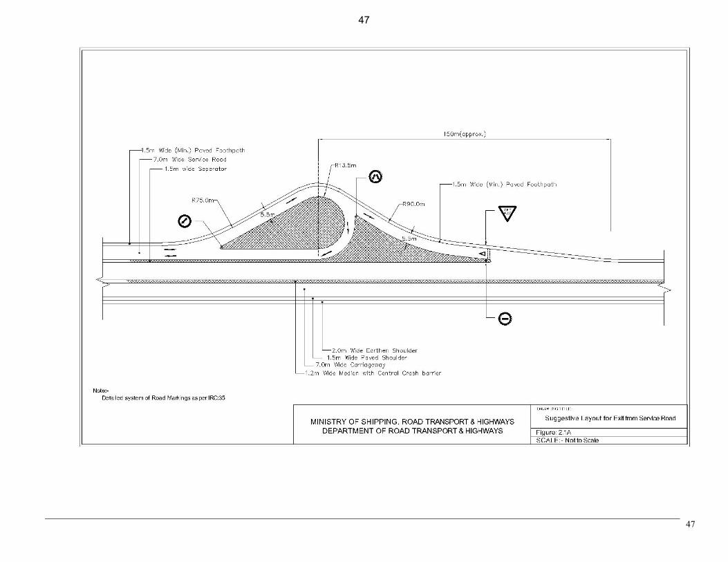
for Road/Bridge works 9. Suggestive Drawings: i) Layout for exit from service road, Figure 2.1A 47 ii) Layout for entry to service road, Figure 2.1B 48
iii) Layout of service road ending at a junction 49 with cross road, Figure 2.2
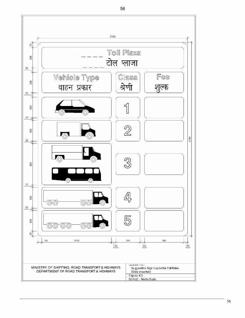
iv) Layout for a toll plaza, Figure 4.1A 50 v) Layout for traffic island with toll booth, Figure 4.1B 51 vi) Sign panel for toll gate at 1 km, Figure 4.2A 52 vii) Sign panel for toll gate at 500 m, Figure 4.2B 53 viii) Sign panel for start of toll road, Figure 4. 2C 54 ix) Sign panel for end of toll road, Figure 4.2D 55 x) Sign layout for toll rates, Figure 4.3 56 xi) Transverse bar markings for
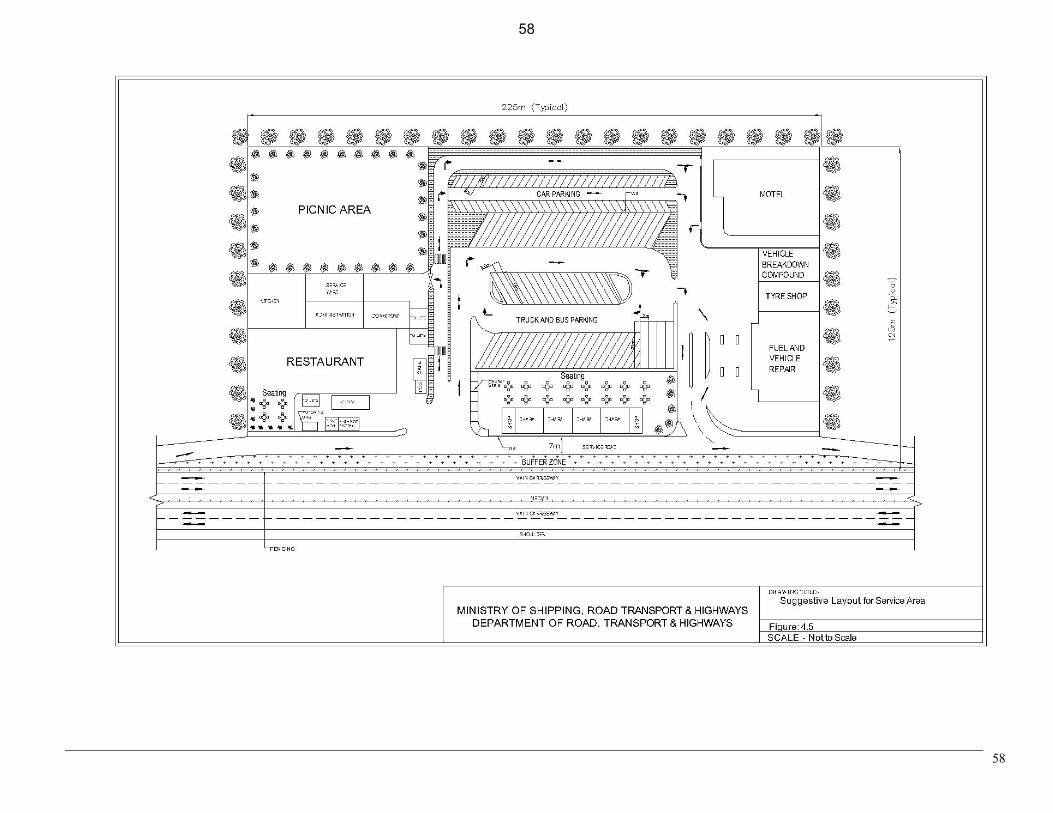
speed control at toll plaza, Figure 4.4 57 xii) Layout for service area, Figure 4.5 58
MANUAL FOR SPECIFICATIONS AND STANDARDS
FOR FOUR LANING OF NATIONAL HIGHWAYS
[See Clause 2.1(a) of Concession Agreement]
SECTION – 1: GENERAL
1.1 This Manual, forming part of Annex-I to Schedule -D of the Concession Agreement (refer Article
2.1(a) of the Concession Agreement), sets forth the Specifications and Standards to be followed
for development of the Project Highway as described in Schedule B and construction of project
facilities as described in Schedule C on the project site as described in Schedule A. The
concessionaire shall make himself fully aware of the Project Site with regard to the existing
features of the site (such as location, layout, geometry, right of way, intersecting roads, existing
accesses , etc) including the constraints at the site (such as limitation of right of way, existence of
adjoining property, existing structures, plantation, utilities, etc), plan, design and construct the
Project Highway comprising its various features (such as four-laning, service roads, underpasses,
overpasses, grade separators, widening/reconstruction of bridges, etc) and the project
facilities(such as toll plazas, rest areas, lighting, landscaping, wayside amenities, etc) meeting the
standards, specifications and quality specified in this Manual.
1.2 Any project report and other information provided by the Authority shall be used by the
concessionaire only for reference purpose and for carrying out further investigations. The
concessionaire shall be solely responsible for undertaking all necessary surveys, investigations
and other due diligence and shall have no claim against Authority for any loss, damage, risk,
costs, liabilities or obligations arising out of or in relation to the project report and other
information provided by the Authority. 1.3 General consideration of planning, design and construction
The Project Highway shall be planned as a “partially controlled access highway” where access to
the highway shall be provided only at pre-determined locations. In doing so, the concessionaire
shall take measures to overcome the physical and operational constraints and plan, design and
construct the Project Highway using appropriate methods, management techniques and
technologies. General consideration shall, without being limited to, be as follows:-
(a) The constraints
The physical constraints in the existing highway are in the form of limitation of right of
way, un-regulated access, inadequate service roads and underpasses, numerous at-grade 1
1
junctions, lack of physical separation between local and through traffic etc. The
operational constraints arise out of the necessity or possibility of closing a portion of the
road for construction and/or diverting the traffic to temporary diversions, thereby
reducing the capacity and safety of the existing highway. The solutions evolved by the
concessionaire shall be such that these operational constraints are overcome through
appropriate planning, design and construction method, techniques and technologies and
by adopting suitable traffic management measures.
(b) Safety of design
All designs shall be safe to ensure that the Project Highway or any part thereof (for
example embankment, pavement, retaining structures, bridges, culverts, etc) does not
collapse nor its serviceability/performance (for example settlement, roughness,
undulations, deflections, etc) deteriorates below acceptable level as prescribed in
Schedule K of the Concession Agreement.
(c) Durability
The Project Highway shall not only be safe but also durable. This would mean that the
deteriorating effects of climate and environment (for example wetting and drying,
freezing and thawing, if applicable, temperature differences, aggressive environment
leading to corrosion etc) shall be duly considered in design and construction to make the
Project Highway durable.
(d) Mitigating disruptive effects of construction
The planning, design and construction of the highway shall be such that the construction
of Project Highway does not disrupt the lives and business activities of the people living
close to the highway.
1.4 Acceptable Standards
1.4.1 The concessionaire shall follow latest version, issued at least 60 days before the last date of bid
submission, of following Indian Standards, Specifications, Codes of Practice, Guidelines, etc for
planning and design in the following order of priority:
i) Technical circulars issued by MOSRTH and published by Indian Roads
Congress/available on MOSRTH website in so far as they relate to design and
construction.
ii) Specifications for Road and Bridge Works issued by the Ministry of Shipping, Road
Transport & Highways hereinafter referred as MOSRTH or Ministry’s Specifications.
iii) Indian Roads Congress (IRC) Codes and Standards; as per Appendix D-1.
iv) Bureau of Indian Standards (BIS) in the absence of any specific provision/issue in the
aforesaid Codes and Specifications as per Appendix D-1.
1.4.2 Wherever Indian standards are either not available or if available but not adequate, the
concessionaire shall be permitted to adopt international standards and specifications as followed
in United States of America, United Kingdom, European Union, Japan, Germany or Australia.
2
2
The concessionaire shall submit proposal in this regard to the Independent Engineer (IE - see
Article 23 of Concession Agreement) for review and comments.
1.4.3 All items of building works shall conform to Central Public Works Department (CPWD)
specifications and norms stipulated in the National Building Code (NBC) as amended from time
to time. In case of conflict between CPWD and NBC norms, NBC norms shall prevail. To the
extent specific provisions for building works are provided in IRC/MOSRTH specifications, the
same shall prevail over the CPWD and NBC provisions. For this purpose, building works shall
also deemed to include roadside facilities, landscape elements and/or any other works incidental
to the building works. All items of lighting works of the building shall conform to CPWD
Specifications for Electric Works (Part I and II).
1.4.4 The concessionaire shall also be permitted to use proprietary or patented designs subject to the
condition that the concessionaire shall be solely responsible for their performance and durability.
1.5
1.6
1.7
1.8
Overall Scheme
The concessionaire shall prepare and submit, in accordance with provisions of this Manual and in
compliance with Article 12.1 of the Concession Agreement detailed design, construction
methodology, quality assurance procedure and operation of the Project Highway and project
facilities to the IE for his review. If, on review, the scheme is not found to conform to the
provisions of this Manual, the concessionaires shall modify the scheme to make it conform to the
provisions of the Manual. Increase in cost due to any modification suggested by the IE shall not
be a reason for the concessionaire objecting to or contesting these modifications. The
concessionaire shall proceed with the implementation of the project as per the scheme so
modified.
Clarificatory role of Manual
Where the provisions of the Concession Agreement are general in nature, the provisions of this
Manual shall be deemed to clarify or amplify these provisions.
Drawings to have comprehensive meaning
“Drawings” referred to in Article 12.3 of the Concession Agreement shall not have a restrictive
meaning but shall include charts, sketches, explanatory notes and documents explaining the
design assumptions, designs, construction methodologies, etc which can demonstrate that
“Drawings” conform to the provisions of this Manual. All drawings specifically referred to in this
Manual shall form part of Schedule H of the Concession Agreement.
Interpretation of the Manual
(1) In case of any conflict between provisions of this Manual and IRC codes or Ministry’s
specifications, provisions of this Manual shall prevail.
3
3
(2) Decision with regard to conformity or otherwise of the provisions of this Manual shall
rest with the IE.
1.9
1.10
1.11
1.12
The concessionaire shall keep the existing utilities in continuous satisfactory use as per Article 11
of the Concession Agreement. Wherever existing utilities are to be shifted and/or new utilities
are to be provided during the concession period, the same shall be accommodated within the
utility corridor of 2.0 m width identified at the edges of the ROW subject to approval by the
Authority.
This Manual is applicable for four laning of the Project Highway. However, some sections of the
Project Highway, as specified in schedule B, are required to be widened to six lanes, which
should not be construed to six laning of the Project Highway. For six laning of such sections,
design shall be finalized based on review & comments of IE.
The terms ‘Ministry of Surface Transport’, ‘Ministry of Road Transport and Highways’ and
‘Ministry of Shipping, Road Transport & Highways’ or any successor or substitute thereof shall
be considered as synonymous.
The terms ‘Inspector’ and ‘Engineer’ used in MOSRTH Specification shall be deemed to be
substituted by the term ‘Independent Engineer’; to the extent its duties and functions are
consistent with the provisions under ‘ARTICLE 23’ of the Concession Agreement and this
Manual. For avoidance of doubt, it is clarified that the role of ‘Independent Engineer’ is to
‘review and comment’, whereas approval will be accorded by the ‘Concessionaire’/ ‘Engineer’
appointed by the ‘Concessionaire’ taking into account comments of ‘Independent Engineer’.
4
4
SECTION – 2: PLANNING THE PROJECT HIGHWAY
2.1 GENERAL
The concessionaire shall plan for capacity augmentation and design the Project Highway in a
manner that will ensure safe operation of the Project Highway as a “partially controlled access
highway”. The concept of providing forgiving highway to the road users shall be kept in mind
while planning and designing the Project Highway. For safe operation, high speed traffic and slow
traffic/local traffic shall be separated by constructing parallel service roads wherever required
and/or specified under Schedule B.
2.2 Operational Objectives of the Project Highway
The Project Highway will be operated as a partially controlled access highway so as to
substantially improve the safety and operational efficiency of the existing highway. The partial
control for the Project Highway shall be achieved through measures such as service road with
physical separation for local traffic, intersections, acceleration/deceleration lanes, vehicular and
pedestrian underpasses, median openings with shelter lane as described in succeeding paragraphs.
2.2.1 Service road for separation of local traffic:
Local traffic in built up areas as specified in Schedule B of the Concession Agreement or
identified subsequently shall be separated with provision of service roads. Built up area shall
mean all sections of the Project Highway, which are situated within the limits of municipal
town(s) and shall also include those sections having continuous length of 200 m or more in non-
municipal areas where dwellings / shops have been built on one or both sides of the Project
Highway on at least 50 percent of the total length of each such section.
The service roads shall be provided with end treatment so that the local traffic is able to diverge
from and merge to the highway in a safe & efficient manner. Two common situations to be dealt
are as below:
(i) Service road not terminating at intersection:
Acceleration / deceleration lane shall be provided for exit/entry of traffic from/to the
Project Highway as the case may be. For allowing two-way traffic on service road, a
separate channeliser shall be provided for U-turns at the end(s) of service road.
Suggestive layouts are given in fig. 2.1(A) & 2.1(B).
(ii) Service road terminating at intersection:
The right turning traffic from the service road wanting to merge/cross the traffic on
highway shall be through a priority intersection between the service road and the cross
road with give way signs and markings. The left turning local traffic from the service
road shall join the cross road through acceleration lane. The acceleration and the give way
lane shall be separated through a channeliser. A suggestive layout is given in fig. 2.2.
5
5
2.2.2 Intersection:
(i) Grade separated intersections:
Grade separated intersections shall be provided at all intersections of Project Highway
with National Highways and State Highways. Grade separated intersections shall also be
provided at all other intersections of Project Highway with other category roads as per
warrants specified in IRC 92 and at locations specified in schedule B.
(ii) At grade intersection;
All intersections other than those covered in (i) above shall be designed as at-grade
intersections in following manner:
a) All merging and diverging movements to / from the Project Highway shall be
either through service road with end treatment or acceleration and deceleration
lanes except for the traffic allowed to cross Project Highway at predetermined
locations.
b) If the road is crossing the Project Highway, the four arm at-grade intersection
shall be designed in accordance with MOSRTH standard drawings. In case the
standard drawing has not provided the right turning lane, the same would be
provided to accommodate the peak hour right turning traffic.
c) If the road meets the Project Highway at T- intersection, this would be designed
as “left in left out”. The right turnings from such cross roads shall be permissible
at the next intersection or median opening.
2.2.3 Access from private property:
Ingress/egress to/from commercial and industrial properties including retail outlets shall be
provided through acceleration/deceleration lane in accordance with MOSRTH guidelines.
2.2.4 Pedestrian/cattle underpasses:
In urban / built up areas, pedestrian / cattle crossing facility shall be provided such that
pedestrians do not have to walk more than 0.5 km to reach the underpass for crossing the Project
Highway. In case the existing slab culverts and minor bridges with span length equal to or more
than 5.0 m allow a vertical clearance of more than 2m, these can also be used for pedestrian and
cattle crossings by providing necessary flooring, provided the culverts/minor bridges do not cater
to perennial flow. In rural stretches, under passes shall be provided at the locations of existing
crossing points.
2.2.5 Median openings:
Median openings shall be provided at four or more arm intersection and at other locations to
facilitate the U-turn for vehicles and not for leading directly to any cross road. The average
spacing of median openings shall be around 2 kms. If a number of roads are meeting the Project
6
6
Highway, then they would be joined together through a service road and an at-grade ‘T’
intersection would be provided such that the spacing of 2 kms for median openings is maintained.
2.2.6 Traffic signs and road markings for guidance to user:
(i) The Project Highway shall be provided with elaborate system of traffic signs and
markings. The traffic signs for various situations/location would be in accordance with
IRC 67 in terms of location, configuration and colour scheme.
(ii) Pavement marking shall also be carefully planned depending upon the requirement for
each location and shall conform to IRC-35. The Project Highway shall incorporate all
such safety features such as elaborate system of signs and markings, cat’s eyes,
delineators, hazard markers, safety barriers at hazardous locations, pedestrian guardrails
so that the Project Highway operates as a “Forgiving Highway”.
2.3 User Facilities:
2.3.1 Rest Areas:
The Project Highway shall have rest areas as specified in Schedule C and be provided with
facilities for the users so as to provide safe and comfortable journey. For this purpose, rest areas
shall be planned with composite facilities for long distance travelers through personal cars, buses
and goods vehicles. Due consideration shall be given to the requirements of different class of
road users including truck drivers.
Wherever some eateries or informal rest area exist and cannot be relocated or accommodated
within the planned rest area, they would be provided with safe entry and exit with signs and
markings.
2.3.2 Bus-Bays:
If the Project Highway has regular movement of buses either through Government or through
private sector, bus bays shall be planned, designed and provided for the convenience of bus
commuters and safe and unimpeded travel on Project Highway.
2.3.3 Advanced Traffic Management Systems (ATMS):
The Project Highway shall be provided with ATMS so as to have enhanced safety for the users /
travellers, collect information for the traffic operations, provide information to the users on real
time basis for the traffic flow conditions and incidents ahead. For this purpose, there would be a
control centre and outdoor equipment connected through a transmission medium.
2.3.4 Highway Patrol:
The Project Highway shall be provided with highway patrol unit(s) for round the clock patrolling
so as to provide assistance to the users in case of any need, monitor the travel conditions to
provide information to the control section and to undertake immediate measures for managing the
traffic flow in case of any incident.
7
7
2.3.5 Ambulance(s):
The Project Highway shall be provided with ambulance services so that the response time is not
more than 10 minutes of the call.
2.3.6 Crane(s):
The Project Highway shall be provided with crane(s) with capacity to tow-away the disabled
vehicles.
2.4 Avenue/median plantation:
The Project Highway shall have plantation of trees along the highway and low height shrubs on
the medians.
2.5 Drainage:
The Project Highway shall be provided with an elaborate drainage system to drain the storm water
from the roadway and embankment and to ensure minimum disturbance to natural drainage of
surface and subsurface water of the area.
2.6 Toll Plaza:
The Project Highway shall have toll plaza(s) as per the requirements and stipulations contained in
Schedule C of the Concession Agreement.
2.7 Operation and maintenance centre:
The Project Highway shall have operation and maintenance centre(s) for carrying out operation
and maintenance activities of the Project Highway.
2.8 New concepts, technologies and materials:
The Concessionaire would be permitted to adopt new technologies and materials as per the
requirements of either design or result of Environmental Impact Assessment (EIA) and
Environmental Management Plan (EMP) (e.g. noise barriers) or providing cost effective solutions.
These shall be subject to the review by I E for their design and adoption.
2.9 Planning drawings:
The concessionaire shall plan the Project Highway conforming to the requirements spelt out
above and submit Kilometre-wise strip plan for the entire project length schematically depicting
therein the location of all features specified in Schedule B as well as the project facilities specified
in Schedule C clearly indicating the existing features and proposed improvement plan to the IE
for review and comments. The submissions shall also include a 3-D animated perspective (To
give a drive through vision) of the Project Highway showing the proposed improvements and
main features.
8
8
SECTION -3: SURVEY AND INVESTIGATIONS
Detailed topographic survey, traffic survey, hydraulic & drainage survey, road and bridge inventory and
condition survey, subsurface investigation, material survey and pavement investigation shall be carried
out in accordance with IRC: SP:19,IRC: SP: 35 & IRC: SP:54 and best industry practices. Latest
technologies and equipments shall be used for undertaking these surveys and investigations. The data
generated from these surveys and investigations shall be documented and presented in the form of
drawings, tables and charts in electronic as well as hard copy formats in accordance with above said IRC
publications and shall along with the detailed drawings prepared in accordance with section 4 of this
Manual form part of Schedule H to the Concession Agreement. The data generated form these surveys
shall be used for detailed design in accordance with section 4 of this Manual.
9
9
SECTION - 4: DESIGN
4.1 General
The designs shall be based on the detailed survey and investigation data collected by the
concessionaire in accordance with Section 3 of this Manual. The drawings prepared on the basis
of these designs along with the drawings required as per Section 3 of the Manual shall form part
of Schedule H of the Concession Agreement.
All the designs and drawings shall be submitted to the I E for review and comments. The work
shall be carried out in accordance with these drawings and such other additional drawings
prepared or modified as per comments of the I E.
4.2 Geometric Design:
Geometric design of the highway, except for cross sectional requirements, shall be in accordance
with IRC: 73, IRC: 86, IRC: 38 and IRC SP: 23. Uniformity of design standards shall be
maintained throughout the length of Project Highway. All deficiencies in the existing highway
geometry shall be rectified to meet the minimum standards specified in this Manual. The detailed
plans, L-sections, cross-sections, strip plans and plans of other facilities of the existing highway to
be prepared by the concessionaire shall be used for developing the layout of various features of
the Project Highway.
4.2.1 General cross-sectional requirements:
The design of cross section of the four lane highway shall take into account the following general
requirements:
(i) The developed cross sections for both the highway as well as the service road shall have
operational safety in focus such as segregation, separation, turning radii, gradients, etc
and provisions for various types of movements and maneuvers like merge, diverge,
weave, etc shall be comprehensively considered and provided for.
(ii) Provisions shall be made in the cross-section for accommodating utilities both over as
well as underground as the case may be. A 2.0 m wide strip of land at the extreme edge
of ROW may be kept for accommodating utility services. Provisions contained in IRC 98
shall be followed to accommodate utility services for Project Highway in built up areas.
4.2.2 Specific cross sectional requirements
The cross section shall provide for the following:
10
10
4.2.2.1 Rural Sections
(i) Minimum width of median
(a) Raised median with mountable kerb (as per IRC: 86) 4.5 m
(b) Depressed median with crash barriers on both sides 7.0 m
(ii) Paved carriageway on both sides of median
(a) 2-lane carriageway with each lane of 3.5 m width 7.0 m
(b) Median side paved strip adjacent to carriageway having
same specification as main carriageway in case of
(i) Raised median 0.50 m
(ii) Depressed median 0.50 m
(c) Paved shoulder on left side of the pavement having same
specification as main carriageway
(i) Plain and rolling terrain 1.50 m
(ii) Mountainous and steep terrain
- Both carriageways side by side 1.50 m
- Two carriageways with separate alignments
(On both sides of carriageway) 1.00 m
(iii) Width of earthen shoulder
(a) Plain and rolling terrain 2.00 m
(b) Mountainous and steep terrain
- Both carriageways side by side 2.00 m
- Two carriageways with separate alignments –on valley side 2.00 m
(iv) Side drain
Cross section shall be designed to cater for effective drainage of estimated peak hour run
off.
(v) Width of utility corridor on both sides 2.0 m
4.2.2.2 Urban/ Built up Sections
(i) Minimum width of median
(a) Flush median with central crash barrier 2.0 m
(b) Raised median with central crash barrier 1.2 m
11
11
(ii) Paved carriageway on both sides of median
(a) 2-lane carriageway with each lane of 3.5 m width 7.0 m
(b) Median side paved strip adjacent to carriageway of same
specification as main carriageway in case of
(i) Raised median 0.50 m
(ii) Flush median excluding crash barrier full width
(c) Paved shoulder on left side of the pavement having same
specification as main carriageway
(i) Plain and rolling terrain 1.50 m
(ii) Mountainous and steep terrain
- Both carriageways side by side 1.50 m
- Two carriageways with separate alignments
(On both sides of carriageway) 1.00 m
(iii) Width of earthen shoulder
(a) Plain and rolling terrain 1.50 m
(b) Mountainous and steep terrain
- On valley side with no habitation at road level 2.00 m
- On hill side and valley side with habitation at road level: may be dispensed with
(iv) Width of service roads 7.0 m
(v) Minimum width of separation-island between main carriageway
and service road 1.5 m
(vi) Minimum width of footpath 1.5 m
(vii) Side drain
Cross section shall be designed to cater for effective drainage of estimated peak hour run
off.
(viii) Width of utility corridor on both sides 1.5 m
Side drain and utility corridor can be accommodated either under footpath or separation-island
depending upon local situation.
12
12
4.2.3 Design Speed:
The design speeds given in following table shall be adopted for various terrain conditions.
Design speed (km/hr) Nature of Terrain
Cross slope of the country
(per cent) Ruling Minimum
Plain 0 - 10 100 80
Rolling > 10 - 25 80 65
Mountainous > 25 - 60 50 40
Steep > 60 40 30
Short stretches (say less than 1 km) of varying terrain in the project stretch shall not be taken into
consideration while deciding the terrain classification for a given section of Project Highway.
In general, the ruling design speed shall be adopted for geometric design of the highway. Only in
exceptional circumstances minimum design speed may be adopted where site conditions are
extremely restrictive and adequate land width is not available. Abrupt changes in design speed
shall be avoided.
4.2.4 Horizontal Alignment:
(a) While designing the horizontal alignment, the following general principles shall be kept
in view.
i. Alignment should be fluent and blend well with the surrounding topography.
ii. On new roads, the curves should be designed to have largest practical radius but
in no case less than ruling value corresponding to ruling design speed.
iii. As a normal rule, sharp curves shall not be introduced at the end of long tangent
since these can be extremely hazardous.
iv. The curves shall be sufficiently long and have suitable transitions to provide
pleasing appearance.
v. Reverse curves may be needed in difficult terrain. Sufficient length between two
curves shall be provided for introduction of requisite transition curves, and
required superelevation.
vi. The curves in the same direction separated by short tangents known as broken
back curves should be avoided as far as possible. Wherever possible, such
portion may be designed with longer single curve.
vii. To avoid distortion in appearance, the horizontal alignment should be coordinated
carefully with the longitudinal profile.
(b) All horizontal curves shall consist of circular portion flanked by spiral transitions at both
ends.
13
13
(c) Radii of Horizontal Curves
The radius of horizontal curves for various terrain conditions shall not be less than the
ruling minimum values as per IRC: 73 for the National Highways and the terrain of the
project area except where site conditions are restrictive and adequate land is not available.
Where such restrictions exist, the radius of curve shall not be less than the specified
absolute minimum values in IRC: 73.
(d) Transition curves
Minimum length of transition curve shall be as per IRC: 73 for the specified design speed.
4.2.5 Camber/Cross fall
Camber / unidirectional cross fall shall be provided for each carriageway including paved
shoulders in accordance with stipulations of IRC: 73. The cross fall for earthen shoulder shall be
0.5% steeper than that of the carriageway subject to a minimum of 3.0%. On curves, the shoulder
on the high side of superelevated portion shall be provided with reverse slope from the
superelevated carriageway portion. At the same time, it should not be too great to give break in
the cross slope. The rate of change between pavement cross slope and outside shoulder should
not exceed 5%.
4.2.6 Super elevation
4.2.7 Super elevation shall be provided on curves as per details given in IRC: 73 corresponding to the
design speed and radius of horizontal curve adopted.
4.2.8 Sight Distance
The design shall provide for values of intermediate sight distance as per details given in IRC: 73
corresponding to the design speed adopted unless there are site constraints, where a minimum of
stopping sight distance shall definitely be available. The requisite site distance shall be available
across the inside of horizontal curves. Where horizontal and summit curves overlap, the design
shall provide for the required sight distance both in the vertical direction along the pavement and
in the horizontal direction on the inside of curve.
4.2.9 Vertical Alignment:
(i) The vertical alignment shall provide for a smooth longitudinal profile. Grade changes shall
not be too frequent as to cause kinks and visual discontinuities in the profile. In this regard,
directions given in IRC: 73 shall be kept in view.
(ii) There shall be coordination between horizontal alignment and vertical profile of the Project
Highway and guidelines given in IRC: 73 in this regard shall be followed.
(iii) Gradients up to the value corresponding to ruling gradient as per IRC: 73 shall be adopted as
far as possible. Value corresponding to limiting gradient shall be adopted only in very
difficult situations and for short lengths.
(iv) Long sweeping vertical curves shall be provided at all grade changes. These shall be designed
as square parabolas.
14
14
(v) The vertical profile of the two carriageways shall be designed in such a manner that
difference in road level between the two carriageways at the locations of median openings
would not be more than 0.25m.
(vi) The aspect of efficient drainage shall also be kept into consideration while designing vertical
profile and cross-sections of the highway as stipulated in IRC: SP: 42 and IRC: SP: 50.
4.2.10 Geometric design requirement of additional features:
a. Acceleration Lane:
(i) Length: Designed for a speed differential of 60 kph
(ii) Width: 5.5 m
(iii) Taper at merge: 1 in 15 beyond design length.
b. Declaration lane:
Same as ‘acceleration lane’
c. Median Openings:
Length of median opening: Not less than 20 m
Shelter lane: Width 3.5 m; Length based on maximum number of right turning
vehicles in peak hour
d. Service Roads:
Design Speed: 40 km/hr (minimum)
Width: Carriageway 7.0 m
Paved shoulder 0.5 m on both sides (may be dispensed with in
exceptional circumstances)
Camber/ Super elevation: As per IRC (Unidirectional camber towards drain shall
be provided)
Extra widening: To be provided at flares for underpass approaches,
adequate turning radius, U-turn facility etc as per
requirement.
Gradient: 1 in 30 (ruling min) underpass approaches – 1 in 50
generally, max 1 in 30.
e. Bridges for service road:
(i) If total length of bridge required to be constructed is less than 60 m, on a stream, the
service road shall continue across the stream through separate bridge structures,
which may be vented causeway structure with vents designed to cater for ordinary
flood discharge.
15
(ii) In cases involving bridges of length 60 m or more, separate bridge structures shall not
be provided and service roads on both side of the stream shall be merged with the
Project Highway. In such cases, width of bridge to be constructed for main highway
15
shall be increased by one traffic lane (i.e. 3.5 m) on both sides of carriageway to
accommodate merging traffic of service road. For this purpose, service roads shall be
merged by tapering of the road (1 in 20) with detailed system of signs and markings.
(iii) In cases of ROBs, the service roads on both the sides shall be joined through one of
the viaducts of ROB. This arrangement shall be on either side of the railway crossing
if the situation demands. For some proportion of service road traffic, safe entry and
exit shall be provided from service roads to the ROB.
(iv) Bridges in built up area will invariably accommodate footpath unless specified
otherwise in Schedule-B.
f. Junctions at Service Roads:
(i) With minor merging roads: Flaring at the junction like a ‘left-in left-out’
configuration but with provision for right turning through painted channelising island.
(ii) At underpasses: Flaring at the junction with provision of painted channelising island
to guide traffic movement to / from the underpass.
g. Vehicular Underpasses:
Width : 7.5 m minimum
10.5 m (with footpath of 1.5 m on both sides) desirable
Vertical Clearance : 5.0 m
h. Pedestrian / Cattle Underpass:
Width : 4.0 m minimum
Vertical Clearance : 2.5 m minimum; to be increased to 4.5m, in case certain
categories of animals such as elephant/camel are
expected to cross the Project Highway.
i. At Grade Intersection : At-grade intersections shall be designed as per IRC SP:
41 and layout as per MOST Type Design for intersections on National Highways.
However, these typed designs shall be modified to provide for right turning lanes in the
median, dropped kerbs and gap in channelisers to facilitate pedestrian crossing.
j. Grade Separated Intersection: The layout and design of grade separated interchanges
shall be as per IRC: 92.
16
16
4.3 Embankment
4.3.1 General
The height of the embankment shall be based on the final road levels. The following principles
shall be followed for fixing the road level:
i) The top of sub-grade is at least 1.0 m above the high flood level/high water table/pond
level. However, in exceptional circumstances not covered in the scope of work specified
in Schedule-B, where it is found difficult to fulfill this criterion without needing
reconstruction or raising in substantial length, the criteria may be relaxed depending on
site conditions, ensuring a minimum difference of 0.6 m between the top of sub-grade and
HFL/high water table/pond level.
ii) The road level of the new two-lane carriageway is not lower than the existing carriageway
unless it improves vertical profile and also satisfies all other requirements set out in this
Manual.
iii) To fulfill the minimum free board requirement and provide smooth vertical profile for
portions forming approaches to structures.
iv) To raise the level of stretches of the existing road from drainage considerations as
indicated in Schedule B of the Concession Agreement.
4.3.2 Structural features and design of embankment
i) Embankment shall be designed to ensure the stability of the roadway and shall incorporate
only those materials, which are suitable for embankment construction as per Section 5 of this
Manual.
ii) Side slopes shall not be steeper than 2H:1V unless duly designed slope protection measures
are provided.
iii) Where the embankment is to be supported on a weak stratum it shall be necessary to specially
design the embankment and also adopt appropriate remedial / ground improvement measures.
iv) High embankments (height 6 m or above) in all soils shall be designed from stability
considerations. For design of high embankments IRC: 75 and MOSRTH – Guidelines for
Design of High Embankments may be referred to.
v) The side slopes shall be protected against erosion by providing turfing / vegetative cover,
stone/C.C. block pitching, geo-synthetics, gabion walls or any other measures depending on
the height of the embankment, type of soil involved and susceptibility of soil to erosion as per
IRC: 56. Pitching works on slopes shall be as per MOST Specifications.
4.3.3 Use of Fly Ash for Embankment Construction
(i) Fly ash shall be used for construction of embankment in accordance with guidelines of
MOSRT&H. The embankment shall be designed and constructed in accordance with IRC:
SP-58. The thickness of soil cover shall not be less than 1 m for embankments up to 3 m
height. For high embankments the thickness of soil cover shall be increased as per design.
17
17
(ii)
(iii)
(i)
The side slopes of the embankment shall be protected against erosion as stated in para 4.3.2
(v) above.
The stability analysis of the embankment shall be carried out as per IRC: 75.
4.4 Pavement Design
4.4.1 Type of Pavement.
(i) Unless specified otherwise in Schedule-B, the concessionaire may adopt any type
(flexible/rigid) pavement structure for new construction.
(ii) The concessionaire shall submit proposal with regard to the type of pavement proposed
for strengthening of the existing pavement to IE for review and comments and finalize the
proposal taking into account comments of IE.
4.4.2 Design traffic
Pavement of the main highway shall be designed for the cumulative number of standard axles
of 8.16 tonnes over the design life of 20 years. Service roads shall be designed for repetition
of 10 million standard axles. Base year traffic, axle load distribution, and vehicle damage
factor for design shall be determined on the basis of survey and investigation to be carried out
by the concessionaire in accordance with section 3 of this Manual. The cumulative axle load
for the purpose of design shall not be less than the number of standard axles obtained if the
base year traffic is cumulated at a rate of growth, which is the highest of the following in the
initial 5 years:
(a) 7.5 % per annum for all vehicles
(b) Trend growth of various vehicle categories
(c) Projected Growth rate of revenue assumed in the concessionaire’s cash
flow
(d) Growth determined from secondary socio economic data and elasticity
factors.
and then reduces by 2 (two) percentage points for every 5 year subject to a minimum rate of
growth of 5 % at any point of time.
4.4.3 Design procedures
For widening of the existing flexible pavement to meet the geometric design requirements
specified in this Manual, the thickness and composition of layers for widening shall be
same as that of existing pavement and further deficiencies in thickness shall be made up
by overlay on the entire width of the pavement including paved shoulders. If the 18
18
condition of existing pavement is so deficient that it cannot be improved by overlays, it
will be scarified and the pavement shall be designed afresh.
(ii)
(iii)
(iv)
In case the existing cement concrete pavement is to be widened, the widened pavement
shall be of the same thickness and specification not inferior to that of the existing
pavement. The widened pavement shall be joined with the exiting pavement by providing
longitudinal joints of the same design and specification as that of the existing pavement.
Similarly, the transverse joints with dowel bars of the same design as provided in the
existing pavement shall be provided.
Flexible Pavement
The new flexible pavement shall be designed in accordance with IRC: 37 and
strengthening of the existing flexible pavement in accordance with IRC: 81.
Rigid Pavement
The new rigid pavement shall be designed in accordance with IRC: 58. The existing rigid
pavement may be rehabilitated / strengthened either by rigid or flexible overlays in
accordance with good industry practice subject to review by the IE.
4.4.4 Pavement Performance Indicators and Requirements
i) The pavement performance and structural capacity shall be measured in terms of
objective measurable performance and strength indicators, i.e., roughness, rutting,
cracking and deflection.
ii) The new or strengthened flexible pavement surface on completion shall satisfy the
following standards:
a. Roughness
In each lane measured by Bump Integrator (BI): Not more than 2000 mm/km for each
lane in a km length
b. Rutting
In wheel path measured No Rutting
by 3 m. Straight Edge.
c. Cracking No Cracking
d. Deflection Not more than 0.5 mm characteristic deflection
to be determined as per IRC: 81
e. Other distresses Nil
19
19
(iii) The new or strengthened rigid pavement surface on completion shall satisfy the following
standards:
a. Roughness
In each lane measured by BI Not more than 2000 mm/km for each lane in a
km length
b. Cracking No Cracks other than shrinkage cracks
c. Other distresses such as
scaling, raveling, spalling at edges Nil
4.5 Design of structures
4.5.1 General
i) The complete structure shall be designed to be safe against collapse and to maintain at all
times an acceptable serviceability level. These shall be also designed to be durable to
withstand the deteriorating effects of climate and environment.
ii) All bridges shall have independent superstructure for each direction of travel. Culverts
may have single or independent structure. Width of median in structural portion shall be
kept same as that in the approaches.
iii) In cases where median is kept open to sky, suitable provision shall be made for retaining
the earth likely to spill from median portion of immediate embankment behind abutment
either by extending the abutment wall or constructing a new retaining wall. Care shall
also be taken to merge the wing wall /return wall and flooring of the old bridge with that
of the new bridge.
iv) All bridges shall provide for carriageway width as per para 4.5.5 below. Wherever
specified in Schedule B, the superstructure shall also provide for pedestrian footpath.
v) Utility service, if any, to be taken on the structures shall be as specified in Schedule B of
the Concession Agreement.
vi) Concessionaire is encouraged to adopt innovative/latest techniques in design, construction
and use of new materials. However, in all such cases Concessionaire shall submit all
relevant details along-with guidelines and propriety literature proposed to be followed to
IE for review and comments.
20
20
4.5.2 Type of Structure
i) The concessionaire may choose any type of structure and structural system. Design and
layout of structures shall be aesthetically pleasing to local environment.
ii) Bridge superstructure, substructure and foundation may be of plain or reinforced concrete,
pre-stressed concrete or steel-concrete composite construction.
iii) The following types of structures shall not be accepted
a) Drop in spans with halved joints (articulations)
b) Trestle type frames for substructures
4.5.3 Pipe Culverts
(i) Minimum diameter of pipes for new pipe culverts shall be 1200 mm.
(ii) Existing culverts of diameter 900 mm and above, which are in sound condition and
functioning satisfactorily, may be retained and extended.
(iii) All existing culverts of diameter less than 900 mm shall be dismantled and reconstructed.
(iv) Minimum depth of earth cushion over pipe including road crust shall not be less than
1000 mm for new / reconstructed culverts. In case of existing sound and safe culverts a
minimum cushion of 600 mm may be acceptable.
4.5.4 Design Period
The design discharge shall be evaluated for flood of 50-year return period for calculation of
waterway and design of foundations.
4.5.5 Width of structures The width of the culverts and bridges shall be adopted as below: i) New culverts and bridges
(a) The pipe / slab / box bridges / culverts shall have the same overall width as of the
approach road. Overall width of these structures shall be such that the outer face
of railing/parapet shall be in line with the outer edge of the shoulder. The median
side inner edge of the safety barrier/kerb shall be at a minimum distance of 250
mm from the edge of the carriageway.
(b) All other new bridges shall be constructed to accommodate for six lane
carriageway. In case existing bridge is retained, as mentioned below, for traffic
in one direction, a new three lane bridge shall be constructed for plying of traffic
in other direction. Width of immediate approaches shall be adjusted to provide
smooth transition from approaches to bridge.
21
21
ii) Existing culverts and bridges:
The pipe / slab / box bridges / culverts shall be widened preferably on the outer side so as
to make the deck width same as specified in sub-para 4.5.5 (i) above. The bridges having
2-lane carriageway and deep foundations, T-beam or box type superstructure, which are
difficult to widen may be retained and proper transition between approach and bridge
shall be provided with the help of crash barriers. The wearing coat, damaged bearings and
rubberized component of expansion joints older than 15 years shall be replaced before
commissioning of the Project Highway.
(iii) In cases where bridges are constructed with footpath as per requirement specified in
Schedule B, cross section of immediate approaches shall have extra width and provide for
footpath.
4.5.6 Design loading and stresses
(i) The design loads shall be as per IRC: 6 appropriate for the width of carriageway, type and
properties of stream, location, altitude, etc.
(ii) In Seismic Zones IV & V, necessary precautions against dislodgement of superstructure
shall be taken by provision of reaction blocks or other type of seismic arresters and
increased width of pier/abutment cap.
4.5.7 Analysis and design of structures
All structures and their individual components shall be analysed and designed as per IRC:5,
IRC:18, IRC:21, IRC:22, IRC:24, IRC:40, IRC:78 and IRC:83 (all parts) depending upon the type
of structure / individual component proposed to be provided. The minimum cross sectional
dimensions of each component shall be provided so as to satisfy the requirements specified in
relevant IRC Code. The design shall take into account long term durability, serviceability,
constructability, construction methodology and environmental factors. All river training and
protection works shall be designed in accordance with IRC: 89.
4.6 Earth Retaining Structures
4.6.1 The concessionaire may adopt any type of earth retaining structure keeping in view the site
conditions. The type of earth retaining structure shall be aesthetically pleasing and compatible
with the adjoining structures. Earth retaining structures shall be designed for lateral earth pressure
including inclined surcharge and hydrostatic pressure, if any.
4.6.2 If the retaining structure is a reinforced earth system, the basic design shall be provided by the
system provider and the design shall conform to BS: 8006 in respect of limit state of collapse and
serviceability. Complete design calculations and drawings showing layout of reinforcement and
other details such as drainage arrangements shall be submitted to the IE for review and comments,
if any.
22
22
4.7 Drainage System
The design of drainage system such as surface and sub-surface drainage for pavement, median,
shoulder, high embankment shall be carried out in accordance with IRC: SP: 42 and IRC: SP: 50.
Surface runoff from the main highway, embankment slopes and the service roads shall be
discharged through longitudinal drains, which shall be designed for adequate cross section, bed
slopes, invert levels and the outfalls. If necessary, the walls of the drains shall be designed to
retain the adjoining earth. Where drains are required to be the covered, the cover of the drain shall
be designed for carrying the maximum expected wheel load. The covered drains shall be provided
with iron gratings, strong enough to withstand expected loading.
4.8 Safety Barrier
Safety barrier of concrete/metal beam/wire rope in accordance with MOSRTH guidelines/circular
shall be provided at following locations:
(i) Where height of embankment is 3 m or more,
(ii) Where embankment is retained by a retaining structure,
(iii) Where median is depressed, flushed or having the width less than 4.5 m. The barriers
shall be for both directions of travel,
(iv) On valley side of highway in mountainous and steep terrain.
(v) Between main carriageway and footpath in bridges.
(vi) At hazardous locations identified in schedule B or through safety audit.
4.9 Toll Plazas 4.9.1 Toll plazas shall be designed for projected peak hour traffic of 20 years. The total number of toll
booths and lanes shall be such as to ensure the service time of not more than 10 seconds per
vehicle at peak flow regardless of methodology adopted for fee collection. For purpose of
guidance following parameters are suggested as a capacity of individual toll lane for design
purpose:
(i) Semi-automatic toll lane 240 veh/hour (Automatic vehicle identification but manual
money transanction) (ii) Automatic toll lanes 360 veh/hour
(Automatic vehicle identification and money transanction – smart card)
(iii) Electronic toll collection (ETC lanes) 1200 veh/hour (Toll collection through on board unit and no
stoppage of vehicles)
23
23
4.9.2 Two toll lanes in each direction of travel shall be provided with the system of payment through
smart card and their configuration would be such that one lane in each direction could be
upgraded in future to the system of Electronic Toll Collection (ETC). The implementation of
ETC will be treated as change of scope when concessionaire would be asked to provide for the
same. Not less than 2 middle toll lanes shall be capable of being used as reversible lane to meet
the demand of tidal flow.
4.9.3 The width of each toll lane shall be 3.2 meters, except for the lane for over dimensional vehicles,
where it shall be 4.5 m.
4.9.4 Between each toll lane of the toll plaza, traffic islands are required to accommodate toll booth.
These islands shall be of minimum 25 m length and 1.8 m width. Protective barriers of reinforced
concrete shall be placed at the front of each island to prevent out of control approaching vehicles
crashing into the toll booth. They would be painted with reflective chevron markings.
4.9.5 Toll booth shall be placed at the centre of each traffic island with dimensions to accommodate toll
collector’s desk for toll equipment such as key board and console, video screen, card reader, note
and coin storage, telephone and environmental control system. The toll booth shall have large
glass window to provide the toll collector with good visibility of approaching vehicles. The
bottom of the toll window should be placed at such a height (0.9 m) above ground level so as to
provide convenience of operation. The Toll booths shall be ergonomically designed and vandal
proof. There shall be CCTV camera installed at each booth.
4.9.6 For the movement between toll office and toll booth of each toll lane, an underground tunnel
across all toll lanes shall be provided. Its dimension would be sufficient to accommodate the
required wiring/cable system and for convenient movement of personnel. It should also be
provided with lighting and ventilation system so that the movement is convenient.
4.9.7 The area of toll plaza covering the flared portion shall be provided with concrete pavement. All
the toll lanes and toll booths shall be covered with a canopy. The canopy shall be wide enough to
provide weather protection to toll operators, drivers and facilities. The canopy shall be of
aesthetically pleasing design with cylindrical support columns located at traffic island so that
there is no restriction on visibility and traffic movement. The vertical clearance shall be as
prescribed in this Manual.
4.9.8 The toll plaza shall have lighting system to provide visibility to drivers for the use of facility
especially to access the correct service lane and also to the toll collector. Indian Standard IS:
1944 shall be followed. The minimum requirement of illumination on the road surface of 30 lux
shall be ensured. This would be done by providing high-mast lighting (minimum 25 m height),
lighting at canopy, and lighting inside toll booths. Street lighting shall also be provided on both
side approaches of toll plaza for a minimum length of 500 metres on each side. Power supply
shall be from public power supply system but stand by generating set of the capacity to supply the
required power shall be provided at toll plaza.
24
24
4.9.9 The toll plaza shall be provided with surface and sub surface drainage system so that all the storm
water is drained off efficiently and no ponding or stagnation of water takes place at any area of
the toll plaza.
4.9.10 Toll Plaza shall have fire fighting equipment including smoke detectors and auto visual alarm
system as per section 4.17.1 of National Building Code so that the personnel working in the
complex and the office are not subjected to hazardous situation due to fire.
4.9.11 The semi automatic toll collection system shall be equipped in each entry lane with a vehicle
detector for counting the number of vehicles and their axle number and for identification of the
category of vehicle. The system shall also have a ticket issuing machine for issue of the tickets
for user fee at the press of a button on a touch panel and entry lane controller for controlling the
equipment of the entry lane and for sending the data to the data processing equipment at toll plaza
office. Each toll lane shall have electronically operated boom barrier along with synchronised
system for traffic lights.
4.9.12 The smart card system would comprise the system for vehicle identification, barrier and
synchronize traffic light and payment through smart card. The smart card would comprise
reader/writer conforming to ISO Standards: 1443-A sealed to a National Electrical Manufacturers
Association (NEMA) for Ingress Protection (IP) - 65 having transmission frequency of 13.56
MHz.
4.9.13 The Electronic Toll Collection system shall consist of an on board unit fitted on a vehicle and an
antenna to receive communication for identification of its code and other stored data and a system
for transmitting the data from the on board unit to the reader and from reader to the customer
information management system.
4.9.14 Toll plaza location shall also be provided with system for checking and preventing overloading of
vehicles at toll plaza. For this purpose, weigh in motion systems at each toll lane are to be
installed. Separate space for static weigh bridge and accommodation to store off-loaded goods
from overloaded vehicles shall be provided after the toll barriers for each direction of travel.
4.9.15 Toll plaza shall have a separate office building so as to provide comfortable office space for
manager, cashier & other staff. There shall be separate rooms for T.V. monitors, meetings, toilets,
and for the sale of passes, smart cards, on board units and public interaction. The building shall
have a strong room for keeping the money and a garage to accommodate the security van (during
operation of loading the collected revenue). There shall be parking space in the same campus for
vehicles for the staff and workers and other vehicles engaged in the operation of the Project
Highway.
4.9.16 The toll plaza shall have toll audit system and fraud protection measures. The operations for toll
collection, supervision, auditing and money handling shall be done through the qualified
personnel with numbers so that each operation is efficiently handled.
25
25
4.9.17 Suggestive lay out of toll plaza showing the service lanes, office space, parking space, weigh
bridges is given in fig. 4.1A and that for toll booth in fig. 4.1B.
4.10 Operation and Maintenance Centre
4.10.1 There shall be operation and maintenance centre(s) either at the toll plaza (s) or at any other
location along the highway as identified by the concessionaire. The land for the same shall be
acquired by the concessionaire at his cost and risk. The operation and maintenance centre would
have following minimum facilities:
(i) Main control centre and Administrative block
(ii) Equipment for operation and maintenance and storage space for them.
(iii) Storage space for equipment and material for traffic signs and markings
(iv) Workshop
(v) General garage and repair shop
(vi) Testing laboratory
(vii) Parking space for minimum 4 no. of large vehicles and for other expected vehicle during
peak hours including those for working staff and visitors
4.10.2 All building works shall be designed to meet the functional requirements and shall be compatible
with regional architecture and micro climate. Locally available materials shall be given
preference but not at the cost of construction quality.
4.10.3 The circulation roads and parking spaces in the O&M centre shall be paved to withstand vehicle
loads and forces due to frequent acceleration and deceleration of vehicles. Parking bays / lots
shall have proper cross slope and drainage. The marking of the parking bays shall be as per IRC:
35 to demarcate parking and circulation space. Parking lots shall have illumination as provided in
IS: 1944 (Parts I and II).
4.10.4 The whole campus of operation and maintenance centre shall have system for security with safe
entry and exit.
4.11 Traffic Signs
Unless otherwise provided in this Manual, road signs shall be provided in accordance with IRC:
67.
4.11.1 There shall be corresponding road markings with stop signs, give way signs, merging or diverging
IRC: 19 -1977 Standard Specification and Code of Practice for Water Bound Macadam(Second Revision)
IRC: 20 -1966 Recommended Practice for Bituminous Penetration Macadam (Full Grout)
IRC: 21 -2000 Standard Specifications and Code of Practice for Road Bridges. Section-III Cement Concrete (Plain and reinforced) (Third revision)
IRC: 22 -1986 Standard Specifications and Code of Practice for Road Bridges. Section-VI Composite Construction (First Revision).
IRC: 23 -1966 Tentative Specification for Two Coat Bituminous Surface Dressing
IRC: 24 -2001 Standard Specifications and Code of Practice for Road Bridges. Section-V Steel Road Bridges (First Revision)
IRC: 26 -1967 Type Design for 200-Metre Stones
IRC: 30 -1968 Standard Letters and Numerals of Different Heights for Use on Highway Signs
IRC: 32 -1969 Standard for Vertical and Horizontal Clearances of Overhead Electric Power and Telecommunication Lines as Related to Roads
IRC: 33 -1969 Standard procedure for evaluation and condition surveys of stabilised soil roads.
IRC: 34 -1970 Recommendations for road construction in waterlogged area.
IRC: 35 -1997 Code of Practice for Road Markings (with Paints) (First Revision)
IRC: 36 -1970 Recommended Practice for Construction of Earth Embankments for Road Works
41
41
List of IRC Codes / Standards / Acts for Road/Bridge Works
IRC: 37 -2001 Guidelines for the Design of Flexible Pavements (Second Revision)
IRC: 38 -1988 Guidelines for Design of Horizontal Curves for Highways and Design Tables (First Revision)
IRC: 40 -2002 Standard Specifications and Code of Practice for Road Bridges, Section IV -Brick, Stone and Block Masonry (Second Revision)
IRC: 41 -1997 Type designs for check barriers (First Revision)
IRC: 42 -1972 Proforma for record of test values of locally available pavement construction materials.
IRC: 45 -1972 Recommendations for Estimating the Resistance of Soil Below the Maximum Scour Level in the Design of Well Foundations of Bridges
IRC: 47 -1972 Tentative specifications for built up spray grout.
IRC: 52 -2001 Recommendation about the alignment survey and geometric design of hill roads. (Second Revision)
IRC: 54 -1974 Vertical Clearances at Underpasses for Vehicular Traffic.
IRC: 56 -1974 Recommended Practice for Treatment of Embankment Slopes for Erosion Control
IRC: 57 -1974 Recommended Practice for Sealing of Joints in Concrete Pavements
IRC: 58 -2002 Guidelines for the design of plain jointed Rigid pavements for highways (Second Revision)
IRC: 59 -1976 Tentative Guidelines for the design of gap graded cement concrete mixes for road pavements.
IRC: 61 -1976 Tentative Guidelines for the construction of Cement Concrete Pavements in Hot Weather
IRC: 65 -1976 Recommended practice for traffic rotaries.
IRC: 67 -2001 Code of Practice for Road Signs (First Revision)
IRC: 69 -1977 Space Standards for Roads in Urban Areas
IRC: 70 -1977 Guidelines on regulations and control of mixed traffic in urban areas.
IRC: 71 -1977 Recommended practice for preparation of notations.
IRC: 73 -1980 Geometric Design Standards for Rural (Non-Urban) Highways
IRC: 75 -1979 Guidelines for the Design of High Embankments
IRC: 78 -2000 Standard Specifications and Code of Practice for Road Bridges. Section-VII Foundations & Sub-structure (Second Revision).
IRC: 79 -1981 Recommended Practice for Road Delineators
IRC: 80 -1981 Type Designs for Pick-up Bus Stops on Rural (i.e., Non-Urban) Highways
IRC: 81 -1997 Tentative Guidelines for Strengthening of Flexible Road Pavement Using Benkelman Beam Deflection Technique (First Revision)
IRC: 83 -1999 Standard Specifications and Code of Practice for Road Bridges. Section-IX Bearings Part-I: Metallic Bearings
42
42
List of IRC Codes / Standards / Acts for Road/Bridge Works
Bearings, Part-I: Metallic Bearings.
IRC: 83 -1987 Standard Specifications and Code of Practice for Road Bridges, (Part-II) Section-IX Bearings, Part-II : Electrometric Bearings
IRC: 83 -2002 Standard Specifications and Code of Practice for Road Bridges, (Part-II) Section-IX Bearings, Part-III : POT POT-CUM-PTFE, PIN AND METALLIC GUIDE BEARINGS
IRC: 84 -1983 Code of Practice for Curing of Cement Concrete Pavement
IRC: 85 -1983 Recommended practice for accelerated strength testing and evaluation of concrete for Road and Airfield Constructions.
IRC: 86 -1983 Geometric Design Standards for Urban Roads in Plains
IRC: 87 -1984 Guidelines for the design and erection of false work for road bridges.
IRC: 88 -1984 Recommended practice for lime fly ash stabilised soil base/ sub base in pavement construction.
IRC: 89 -1997 Guidelines for Design & Construction of River Training & Control Works for Road Bridges (First Revision)
IRC: 91 -1985 Tentative guidelines for construction of cement concrete pavement in cold weather.
IRC: 92 -1985 Guidelines for the Design of Interchanges in Urban Areas
IRC: 93 -1985 Guidelines on Design and Installation of Road Traffic Signals
IRC: 98 -1997 Guidelines on Accommodation of Underground Utility Services Along and Across Roads in Urban Area (First Revision)
IRC: 101 -1988 Guidelines for design of continuously reinforced concrete pavement with elastic joints.
IRC: 102 -1988 Traffic studies for planning bypasses around towns.
IRC: 103 -1988 Guidelines for Pedestrian Facilities
IRC: 104 -1988 Guidelines for Environmental impact assessment of Highway projects.
IRC: SP: 4 -1966 Bridge Loading Round the World
IRC: SP: 11 -1988 Handbook of Quality Control for Construction of Roads and Runways (Second Revision)
IRC: SP: 13 -2004 Guidelines for the Design of Small Bridges and Culverts.
IRC: SP: 14 -1973 A Manual for the Application of the Critical Path Method to Highway Project in India
IRC: SP: 15 -1996 Ribbon Development Along Highways and its Prevention
IRC: SP: 16 -2004 Guidelines for surface evenness of Highways Pavements (First Revision)
IRC: SP: 17 -1977 Recommendations About Overlays on Cement Concrete Pavements
IRC: SP: 18 -1978 Manual for Highway Bridge Maintenance Inspection.
43
43
IRC: SP: 19 -2001 Manual for Survey, Investigation and Preparation of Road Projects (First Revision)
IRC: SP: 21 -1979 Landscaping of Road
IRC: SP: 22 -1980 Recommendations for the Sizes for each Type of Road Making Machinery to Cater to the General Demand of Road Works
IRC: SP: 23 -1983 Vertical Curves for Highways
IRC: SP: 25 -1984 Gopi and his Road Roller-Guidelines on Maintenance of Road Roller
IRC: SP: 27 -1984 Report Containing Recommendations of IRC Regional Workshops on Highway Safety
IRC: SP: 32 -1988 Road Safety for Children (5-12 Years Old)
IRC: SP: 33 -1989 Guidelines on Supplemental Measures for Design, Detailing & Durability of Important Bridge Structures.
IRC: SP: 34 -1989 General Guidelines About the Equipment for
IRC: SP: 35 -1990 Inspection and Maintenance of Bridge.
IRC: SP: 37 -1991 Guidelines for Evaluation of Load Carrying Capacity of Bridges
IRC: SP: 53 -2002 Guidelines on Use of Polymer and rubber Modified Bitumen in Road Construction (First Revision)
IRC: SP: 54 -1999 Project Preparation Manual for Bridges
IRC: SP: 55 -2001 Guidelines for Safety in Construction Zones
IRC: SP: 56 -2000 Guidelines for Steel Pedestrian Bridges
IRC: SP: 57 -2001 Guidelines for Quality Systems for Road Construction
IRC: SP: 58 -2001 Guidelines for Use of Fly ash in Road Embankments
IRC: SP: 59 -2002 Guidelines for Use of Geotextiles in Road Pavements and Associated Works
IRC: SP: 60 -2002 An Approach Document for Assessment of Remaining Life of Concrete Bridges
44
44
III Ministry of Surface Transport Publications
MORT&H Pocketbook for Bridge Engineers, 2000 (First Revision)
MORT&H Pocketbook for Highway Engineers, 2002 (Second Revision)
MORT&H Specifications for Road and Bridge Works, 2001 (Fourth Revision)
MOST Standard Plans for 3.0 m Span Reinforced Cement Concrete Solid Slab Superstructure with and without Footpaths for Highways, 1991
MOST Standard Plans for Highways Bridges R.C.C. T-Beam & Slab Superstructure - Span from 10 m to 24 m with 12 m width, 1991
MOST Standard Plans for Highway Bridges PSC Girder and RC Slab Composite Superstructure for 30 m Span with and without Footpaths, 35 m Span with Footpaths and 40 m Span without Footpaths, 1991
MOST Standard Drawings for Road Bridges - R.C.C. Solid Slab Superstructure (15* & 30* SKEW Span 4.0 m to 10.0 m (with and without Footpaths), 1992
MOST Type Designs for Intersections on National Highways, 1992
MOST Computer Aided Design System for High Embankment Problems, 1993
MOST Addendum to Ministry's Technical Circulars and Directives on National Highways and Centrally Sponsored Road & Bridge Projects (Aug. 88 to Dec. 92), 1993
MOST Standard Drawing for Road Bridges R.C.C. Solid Slab Superstructure (22.5* SKEW) R.E. Span 4M to 10M (with and without Footpath), 1996
MOST Addendum to Ministry's Technical Circulars and Directives on National Highways and Centrally Sponsored Road & Bridge Projects (Jan. 93 to Dec. 94), 1996
Standard Plan for Highway Bridges - Prestressed Concrete Beam & RCC Slab Type Superstructure - Volume –II
MOST Addendum to Technical Circulars & Directives on National Highways & Centrally Sponsored Road & Bridge Works Projects (Jan. 1995 to Dec. 1997)
MOST Standard Plans for Single, Double and Triple Cell Box Culverts with and without Earth Cushion
Manual for Safety in Road Design
MORT&H Manual for Construction and Supervision of Bituminous Works, 2001
BIS PUBLICATIONS
IS: 1944 (Part-I & II) 1970
Code of Practice for lighting of Public thoroughfare: Parts Land 2 For Main and secondary roads (Group-A and B) (First revision) (Amendments No. 1 and 2) Parts – I and 2 in one volume) (Amendments-2).
IS: 1944 (Part-V) 1981 Code of Practice for Lighting of Public Thoroughfares: Parts 5 Lighting for Grade separated junctions, Bridges and Elevated roads (Group – D).
IS: 1944 (Part-VI) 1981 Code of Practice for lighting of Public thoroughfare: Part-6 Lighting for Towns and city centres and areas of civic Importance (Group-E).
IS: 10748 – 1995 Hot rolled steel for welded tubes and pipes (First Revision)
NBC National Building Code
45
45
Part-III, NBC: Development Control rules and general building requirements.


![VOLUME - nhai.org.innhai.org.in/spw/Agreement/CA .pdfNATIONAL HIGHWAYS AUTHORITY OF INDIA ... 12.4 [Four-Laning] of the Project Highway ... 17.3 Maintenance Manual ...](https://static.documents.pub/doc/80x56/5b0146717f8b9af1148de833/volume-nhaiorg-pdfnational-highways-authority-of-india-124-four-laning.jpg)


![Computer-Aided Geometric Design of Road and Safety Evaluation … · 2020. 8. 16. · [1] IRC SP 73:2015 “Manual of Specifications and Standards For Two Laning of Highways with](https://static.documents.pub/doc/80x56/6075655594b849732f6d70d5/computer-aided-geometric-design-of-road-and-safety-evaluation-2020-8-16-1.jpg)


