[email protected]Manual for using MED17.5.2 Bosch ECU probe with AVDI – Page 1. 1. Description: This probe can be used for programming VAG MED17.5.2 Bosch ECU`s. It fits in most BDM positioning frames and is fitted with LED`s for accurate alignment on the ECU. The “Boot” resistors and the ignition feed can be switched. With this adapter, there is no need to solder at all. Adapter Overview A = Serial port connection B = Power Switch ON/OFF C = Power Jack D = DIP Switches for BOOT Resistors ON/OFF E = Ignition selection switch: ON/OFF/K-Line Since the AVDI requires a permanent connection via a 510 Ohm resistor between the K-Line and 12V, This switch has no function in the AVDI version of this probe. SET TO “K-Line” POSITION AT ALL TIMES F = Connect to flash tool. G = Connect to serial port on probe (A)
Manual for using MED17.5.2 Bosch ECU probe with AVDI – Page 1.
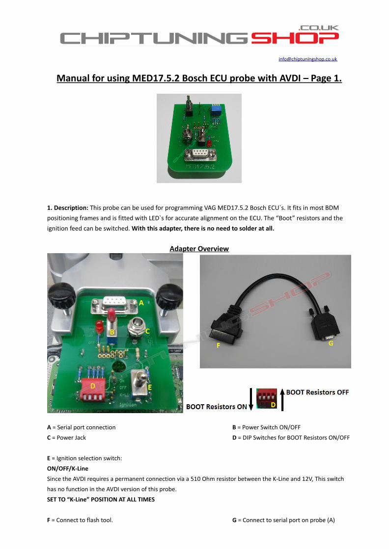
1. Description: This probe can be used for programming VAG MED17.5.2 Bosch ECU`s. It fits in most BDM positioning frames and is fitted with LED`s for accurate alignment on the ECU. The “Boot” resistors and the ignition feed can be switched. With this adapter, there is no need to solder at all.
Adapter Overview
A = Serial port connection B = Power Switch ON/OFF
C = Power Jack D = DIP Switches for BOOT Resistors ON/OFF
E = Ignition selection switch:
ON/OFF/K-Line
Since the AVDI requires a permanent connection via a 510 Ohm resistor between the K-Line and 12V, This switch
has no function in the AVDI version of this probe.
SET TO “K-Line” POSITION AT ALL TIMES
F = Connect to flash tool. G = Connect to serial port on probe (A)
Manual for using MED17.5.2 Bosch ECU probe with AVDI – Page 2.
2. Handling and Adjustment: IMPORTANT - Make sure that the power switch (B) is in the “OFF” position. The power switch must remain OFF so that the pins are not live, until the probe is correctly aligned and in contact with the corresponding pins on the ECU. Failure to follow these instructions could result in damageto the ECU!
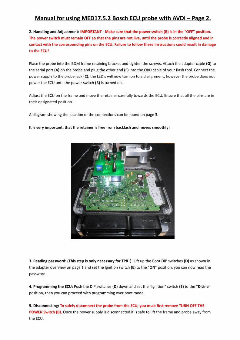
Place the probe into the BDM frame retaining bracket and tighten the screws. Attach the adapter cable (G) tothe serial port (A) on the probe and plug the other end (F) into the OBD cable of your flash tool. Connect the power supply to the probe jack (C), the LED's will now turn on to aid alignment, however the probe does not power the ECU until the power switch (B) is turned on.
Adjust the ECU on the frame and move the retainer carefully towards the ECU. Ensure that all the pins are in their designated position.
A diagram showing the location of the connections can be found on page 3.
It is very important, that the retainer is free from backlash and moves smoothly!
3. Reading password: (This step is only necessary for TP8+). Lift up the Boot DIP switches (D) as shown in the adapter overview on page 1 and set the Ignition switch (E) to the “ON” position, you can now read the password.
4. Programming the ECU: Push the DIP switches (D) down and set the “Ignition” switch (E) to the “K-Line” position, then you can proceed with programming over boot mode.
5. Disconnecting: To safely disconnect the probe from the ECU, you must first remove TURN OFF THE POWER Switch (B). Once the power supply is disconnected it is safe to lift the frame and probe away from the ECU.
Manual for using MED17.5.2 Bosch ECU probe with AVDI – Page 3.
The pads marked in red have to make contact with the probe.
Technical alterations reserved!
Copyright by www.chiptuningshop.co.uk
This product should be operated by competent personnel only. Chiptuningshop Ltd do not accept any responsibility
for damages, direct or consequential caused by improper handling.