23
Fancom B.V. Postbus 7131 5980 AC Panningen, the Netherlands GB F47 MANUAL INSTALLER VERSION A2

Fancom B.V. Postbus 7131 5980 AC Panningen, the Netherlands
GB
F47MANUAL
INSTALLERVERSION A2

Fancom F47 Copyright
FANCOM B.V. Limited Warranty Statement
Fancom expressly warrants each new product manufactured by it to be free from defects in material orworkmanship for two years from the date of initial installation by or for the original purchaser, but inno event shall such period be greater than two years and three months from the date of initial shipmentof the product from the manufacturer's facility. The following warranties are in lieu of any and allrepresentations and warranties, express or implied, including the implied warranties of merchantabilityor fitness for a particular purpose, whether arising from statute, common law, custom or otherwise.Fancom shall not be liable for any special, consequential or incidental damages resulting from the use ofany of the products or caused by any defect, failure or malfunction, whether a claim for such damage isbased upon warranty, contract, negligence or otherwise, and in no event shall Fancom be liable for anydamages in excess of the amount paid for the products. In the event a defect is found by theManufacturer to exist within this period, the Manufacturer will, at its option, (a) repair or replace suchproduct free of charge, F.O.B. the factory of manufacture, or (b) refund to the original purchase price tothe original purchaser, in lieu of such repair or replacement. Labour costs associated with thereplacement or repair of the product are not covered by the Manufacturer.
WARNING: Independent alarm installation
Like all mechanical and electronic devices, the Fancom Control Unit may fail. Thus, when the FancomControl Unit is controlling the environment for confined livestock, it is highly recommended by Fancomthat an independent alarm system be installed. The Fancom Control Unit does provide a connectionport designated for either make or break contact for the sounding of an alarm condition ( please refer toinstallation guide for location ). Failure to comply with the above warning may result in loss of productand/or profits, for which Fancom is not responsible or liable.
Always keep this manual by your computer
January, 2001
All rights reserved. Reproduction of any part of this manual in any form whatsoever without Fancom’sexpress written permission is forbidden. The contents of this manual are subject to change withoutnotice. All efforts have been made to assure the accuracy of the contents of this manual. However,should any errors be detected, Fancom would greatly appreciate being informed of them. The abovenotwithstanding, Fancom can assume no responsibility for any errors in this manual or theirconsequence.
Copyright 2001 Fancom B.V.Panningen, the Netherlands
Art. Nr. 5911333 MODIFICATIONS RESERVEDGB201201

Fancom F47 Table of contents
Table of contents
About this manual
1. Introduction ............................................................................................12. Technical specifications .........................................................................23. Safety instructions and warnings .........................................................3
3.1 General............................................................................................33.2 Trouble ............................................................................................33.3 Installation......................................................................................3
4. Mounting and installation .....................................................................45. Installer settings ....................................................................................6
5.1 Accessing the installer settings .....................................................65.2 Back to the user menu ...................................................................65.3 Installation......................................................................................75.4 Uniformity.......................................................................................95.5 Weighing (for service purposes only)...........................................105.6 Calibration ....................................................................................11
5.6.1 Determining the zero point.................................................115.6.2 Entering the standard weight.............................................12
5.7 System...........................................................................................135.7.1 General .................................................................................135.7.2 Communication....................................................................145.7.3 IO ..........................................................................................14
APPENDIX 1: Overview installer settingsAPPENDIX 2: System alarmsAPPENDIX 3: Address settingsAPPENDIX 4: Connection diagram
Fancom F47 About this manual
About this manual This manual contains information about the installation and service ofthe computer. Read this manual carefully and follow all safetyinstructions. The installer’s settings can then be entered and thecomputer prepared for further use.
This manual has been written by Fancom for the installer. A user’smanual is also available, containing information about the computer'sdaily use.
If you have any questions regarding the computer, please do nothesitate to contact your Fancom dealer. The subjects discussed in thismanual are listed in the table of contents.
The following symbols are used in this manual:
! Suggestions, advice and notes with additional information.
CautionThe product could be damaged, if the procedures are not followedcarefully.
Caution Life threatening situation, if the procedures are not followedcarefully.

Fancom F47
1
1. Introduction
1. Introduction
Fancom has developed the F47 bird weighing computer for continuouspoultry weighing. The weighing system consists of one poultry weighingcomputer and a maximum of two electronic weighing scales.
Communication
It is possible to communicate with the F47 computer via a PC. Viamodems even at great distances. Use the Fancom network (FNet) forcommunication.
Using the Fancom F-Central program on the PC the increasing growthline of the animals can be shown in graph form.

Fancom F47
2
2. Technical specifications
2. Technical specifications
Power supplyMains voltage 85Vac-263VacMains frequency 50/60HzMaximum power consumption 25VA
Available power for sensors and peripheral equipment24Vdc (fused) max. 500mA
Analog inputs2 analog inputs for the scales max. length 50m
HousingPlastic housing with screw on lid IP54Dimensions (l×w×h) 300×240×140mm/11.8×9.4×5.5 insWeight (unpacked) 3.0kg/6.6lbs
Ambient climateOperating temperature range 0°C to +40°C/32°F to 104°FStorage temperature range -10°C to 50°C/14°F to 122°FRelative humidity < 95%, uncondensed
Communication♦ FNet Fancom network for intercommunication of Fancom computers
and connection to PC *.♦ I/O-Net for I/O modules for scales at distances exceeding 50m*
* For wiring data, see connection diagrams.
Fancom F47
3
3. Safety instructions andwarnings
3. Safety instructions and warnings
3.1 General
Read the safety instructions and conditions carefully before installingand using the computer. The installation of the computer and troubleshooting must be carried out by an authorized technician/installer,according to the prevailing standards.
Fancom takes no responsibility for any possible damage as a result ofincorrect settings and a non- or partially functioning installation.
3.2 Trouble
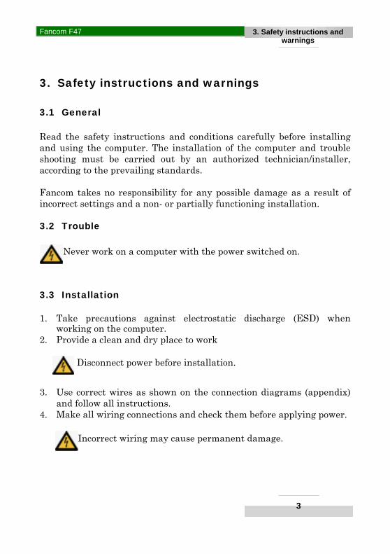
Never work on a computer with the power switched on.
3.3 Installation
1. Take precautions against electrostatic discharge (ESD) whenworking on the computer.
2. Provide a clean and dry place to work
Disconnect power before installation.
3. Use correct wires as shown on the connection diagrams (appendix)and follow all instructions.
4. Make all wiring connections and check them before applying power.
Incorrect wiring may cause permanent damage.

Fancom F47
4
4. Mounting andinstallation
4. Mounting and installation
Caution
It is essential that the alarm output of each computer is connected to aseparate alarm system circuit.When mounting the computer, the following should be observed:
1. Never mount the computer near water pipes, drainage pipes etc.2. Never mount the computer in a place where the weather has direct
influence (not in the sun, or in places where the temperature canrise sharply, etc.).
3. Never mount the computer in a humid and/or dusty room andcertainly not in the room where the animals are present.
No condensation may take place in or on the computer.
4. Use the holes behind the cover screws on the corners of the box tosecurely fasten the computer.
5. Mount the computer on a flat surface with the display at eye level( or slightly higher). Ensure that the gland nuts are at the bottom ofthe computer.
6. Use gland nuts to connect the computer. Use the sealing platessupplied to seal the gland nuts which are not used. Seal all glandnuts after connection to prevent the entry of dust, aggressive gasesand/or humidity.
7. To protect against lightning, place an over voltage protection devicein the power supply of the computer.

Fancom F47
5
4. Mounting andinstallation
8. Connect each computer to one group from the main electrical servicepanel.
9. It should be possible to disconnect the computer using a switch orplug.
Ensure the computer is well grounded.
10. Separate high/low current wires by mounting them in separatecable channels.
11. If metal cable channels are used, ground them.
Always observe the regulations of the electricity company
! AdviceLimit the length of the signal wires as much as possible; avoidcrossing high/low voltage wires.

Fancom F47
6
5. Installer settings5.1 Access/5.2 Back
5. Installer settings
5.1 Accessing the installer settings
1. Ensure that the main menu is shown on the display (use key ).2. Press 5× quickly. The main installer menu will appear on the
display.
5.2 Back to the user menu
Press . The main user menu will appear on the display.
Weight Read out
History Other
Press 5× quickly
Installation System

Fancom F47
7
5. Installer settings5.3 Installation
5.3 Installation
1. Ensure that the main user menu is shown on the display (usekey ).
2. Press 5× quickly. The main installer menu will appear on thedisplay.
House number Enter a unique house number. This is important if thecomputer has been included in a network (FancomFNet).
Number scales Enter the number of scales connected to this computer(1 or 2).
Installation Weighing
Uniformity Calibrate
House number 4Number scales 1Scale descr. Address SCALE-1 0. 1 SCALE-2 0. 0
To line below
Installation System
Select Installation
Select Installation
Fancom F47
8
5. Installer settings5.3 Installation
Scale descr. Give a suitable name to the scales(s). The keyboardwill automatically accept this alpha function (seesection 4.5 of the user manual).
Address Scale-1 and Scale-2 are connected to address 0.1respectively 0.2 of the computer. Address 1.1 andhigher means that the scales are connected via an I/O-module.

Fancom F47
9
5. Installer settings5.4 Uniformity
5.4 Uniformity
Cal.uniform. Enter how the computer must calculate the uniformitypercentage: based on 10% or 15%. The uniformitypercentage is the percentage of all measurements thatfall within 10% or 15% of the average weight.
Display Enter whether the uniformity percentage or the co-variance is to be displayed.
Installation Weighing
Uniformity Calibrate
CaCal.Cal.uniform. 10%Display UNIFORMITY
Select Uniformity

Fancom F47
10
5. Installer settings5.5 Weighing
5.5 Weighing (for service purposes only)
These settings/ readouts are for service purposes only.
Installation Weighing
Uniformity Calibrate
SCALE-1Counts -399584Weight 2097 COUNTS SPAN FILTER
SCALE-1Span 6634Offset 40478 COUNTS SPAN FILTER
SCALE-1Filter 1.0Stability 3 COUNTS SPAN FILTER
Select data for other scale.
Select FILTER
Select Weighing
Fancom F47
11
5. Installer settings5.6 Calibration
5.6 Calibration
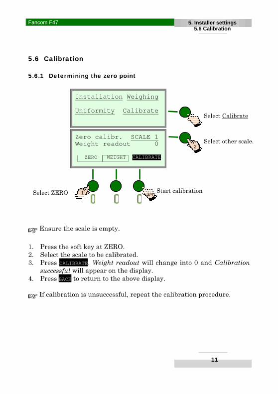
5.6.1 Determining the zero point
! Ensure the scale is empty.
1. Press the soft key at ZERO.2. Select the scale to be calibrated.3. Press CALIBRATE. Weight readout will change into 0 and Calibration
successful will appear on the display.4. Press BACK to return to the above display.
! If calibration is unsuccessful, repeat the calibration procedure.
Installation Weighing
Uniformity Calibrate
Zero calibr. SCALE 1Weight readout 0
ZERO WEIGHT CALIBRATE
Select other scale.
Select ZERO 3/41
2
Start calibration
Select Calibrate

Fancom F47
12
5. Installer settings5.6 Calibration
5.6.2 Entering the standard weight
! There is nothing on the scale.
1. Press the soft key at WEIGHT.2. Select the scale to be calibrated.3. Enter the value of the standard weight at Standard weight (e.g.
3000g).4. Place the standard weight on the scale.5. Press the soft key at CALIBRATE. Successful calibration will appear on
the display.6. Press BACK to return.
! If calibration is unsuccessful, repeat the calibration procedure.
Calib.weight SCALE 1Standard wt. 3000Weight readout 0 ZERO WEIGHT CALIBRATE
Select other scale.
SelectWEIGHT
5/61
2

Fancom F47
13
5. Installer settings5.7 System
5.7 System
5.7.1 General
3. Ensure that the main user menu is shown on the display (usekey ).
4. Press 5× quickly. The main installer menu will appear on thedisplay.
Date and Time The current date and time. The time can be changed,for example when changing from summer to wintertime.
Fancom Computer type.
Version The program version.
CodeID Coded checksum.
General IO
Communication
GeneralGeneralDate 13-12-2001Time 10:09Fancom F47Version: A 1.0CodeID: 8015-D733
To lines below
Installation System
Select System
Select General

Fancom F47
14
5. Installer settings5.7 System
5.7.2 Communication
Computer number Enter a unique computer number. This isimportant if the computer is included in anetwork (Fancom FNet).
! The other data is for service purposes only. It supplies extrainformation about communication for optimal functioning.
5.7.3 IO
! For services purposes only.
General IO
Communication
GeneralCommunicationComputer number 1Messages 0Last error 0Number Busy 0Number Collisions 0Reset counters NO
To lines below
SelectCommunication

Fancom F47
1-1
APPENDIX 1Overview settings
APPENDIX 1: Overview installer settings
INSTALLATION ! INSTALLATIONHouse numberNumber scales 1 / 2 *Scale descr. 1: 2:Address 1: 2:
INSTALLATION ! UNIFORMITYCal.uniform. (%)Display UNIFORMITY / CO-VARIANCE *
INSTALLATION ! WEIGHING**Counts 1: 2:Weight 1: 2:Span 1: 2:Offset 1: 2:Filter 1: 2:Stability 1: 2:
INSTALLATION !CALIBRATEZero calibration 1: 2:Weight readout 1: 2:Weight calibr. 1: 2:Standard weight 1: 2:Weight readout 1: 2:
SYSTEM ! COMMUNICATIONComputer nr.
* Delete where not applicable.** For service purposes only

Fancom F47
2-1
APPENDIX 2System alarms
APPENDIX 2: System alarms
Alarm message Cause Action
FNet alarm No communication with PC. Check wiring and connections.
I/O-Net alarm No communication withI/O-modules.
Check wiring and connections.
I2C alarm No communication betweeninternal prints.
Check wiring and connections.
1, 2 ... 35 Specific system alarms Contact the Fancom Helpdesk.

Fancom F47
3-1
APPENDIX 3Address settings
APPENDIX 3: Address settings
Address settingsSwitch
Address # 1 2 3 4 50 - - - - -1 × - - - -2 - × - - -3 × × - - -4 - - × - -5 × - × - -6 - × × - -7 × × × - -8 - - - × -9 × - - × -
10 - × - × -11 × × - × -12 - - × × -13 × - × × -14 - × × × -15 × × × × -16 - - - - ×17 × - - - ×18 - × - - ×19 × × - - ×20 - - × - ×21 × - × - ×22 - × × - ×23 × × × - ×24 - - - × ×25 × - - × ×26 - × - × ×27 × × - × ×28 - - × × ×29 × - × × ×30 - × × × ×31 × × × × ×

Fancom F47
4-1
APPENDIX 4 Connection diagram
APPENDIX4: Connection diagram F47
LCC
POWER
1 2
3 4
5
+5V R+ R- In+ In-
-+
IOnet
2
1
+5V R+ R- In+ In-
1 2 IOB
.0
C NO NCAlarm
Max 30Vac50Vdc 0.5A
FNET FNET- +
IONET- +
24VdcMax 0.5A POWER IN
FUnC
2
1
+5V Ref+ Ref- Sig+ Sig-
Shield
Shield+5V Ref+ Ref- Sig+ Sig-
L N PE
90-264 Vac 50/60 Hz
OUT
(120Ω)
1=IONET 2=FNET
ON
C NO NCAlarm
Max 30Vac50Vdc 0.5A
FNET FNET- +IONET
- +24Vdc
Max 0.5A
OFF ON

FNet
+ -
CONNECTION I/O NETWORK(control computer and I/O Network modules)
NEVER cut thebackbone cable.
Remove theinsulation only.
CONNECTION FNET(control computers and PCs)
I/O Net
I/O Net
FNet FNet
The order of I/O network modules is not important.
The order of systemsis not important.
Polarity of FNetis not important.
(control computer)
Terminalresistor120 Ω.
Terminalresistor120 Ω.
PC with networkcard (and built-interminal resistor)
(I/O Network module)
(I/O Network module) (I/O Network module)
(Control computer)
Terminalresistor120 Ω.
WIRING OF I/O NETWORK AND FNET:1) Phone cable (unshielded) 2 wire (twisted pair) + a single wire (2x2x0.5mm + 1x0.5mm). One wire pair will not be used.or2) Unshielded 2 wire twisted pair (1x2x0.5mm or 1x2x0.8mm)
Max. length of both networks: wire: ø0,5mm --> 900m. wire: ø0,8mm --> 1300m.
Connect Fancom equipment according to the prevailingstandards of the local electricity company.
The first and last I/O Network modulemust be terminatedwith a resistance
of 120Ω
The first and thelast system must
be terminatedwith a resistance
of 120Ω.
(control computer)
ALTERNATIVE:a solid
solderedconnection
or


![Debian Installer Basics - start [Unix-AG-Wiki] · PDF fileDebian Installer Debian Installer I Installationsmedium für Debian I verschiedene Typen: I CD- und DVD-Installer: für Installation](https://static.documents.pub/doc/80x56/5a79b7b97f8b9ad7608bc8f9/debian-installer-basics-start-unix-ag-wiki-installer-debian-installer-i-installationsmedium.jpg)