WARNINGUnderstand manual before use. Operation of this device without understanding the manual and receiving proper training is a misuse of this equipment. Obtain safety information at www.tft.com/serial-number
This instruction manual is intended to familiarize fi refi ghters and maintenance personnel with the operation, servicing and safety procedures associated with the Metro 0, 1 & 2 fi re fi ghting nozzles.This manual should be kept available to all operating and maintenance personnel.
Table Of Contents1.0 MEANING OF SAFETY SIGNAL WORDS2.0 SAFETY3.0 GENERAL INFORMATION 3.1 VARIOUS MODELS AND TERMS 3.2 SPECIFICATIONS 3.2.1 MECHANICAL 3.3 NOZZLE COUPLINGS 3.4 USE WITH SALT WATER4.0 FLOW CHARACTERISTICS 4.1 METRO 0 4.2 METRO 1 4.3 METRO 2 4.4 FLOW SETTING5.0 NOZZLE CONTROLS 5.1 FLOW CONTROL 5.1.1 LEVER TYPE FLOW CONTROL 5.1.2 TIP ONLY NOZZLES 5.1.3 BALL SHUTOFF 5.1.4 TWIST SHUTOFF 5.1.5 IMPULSE TRIGGER FLOW CONTROL 5.1.5.1 IMPULSE TRIGGER LOCK 5.1.5.2 TRIGGER FLOW CONTROL SPEED ADJUSTMENT 5.1.5.3 NORMAL OPERATING POSITION 5.2 PATTERN AND FLUSH CONTROL 5.2.1 PATTERN CONTROL 5.2.2 FLUSH CONTROL6.0 USE WITH FOAM 6.1 FOAM ASPIRATING ATTACHMENTS
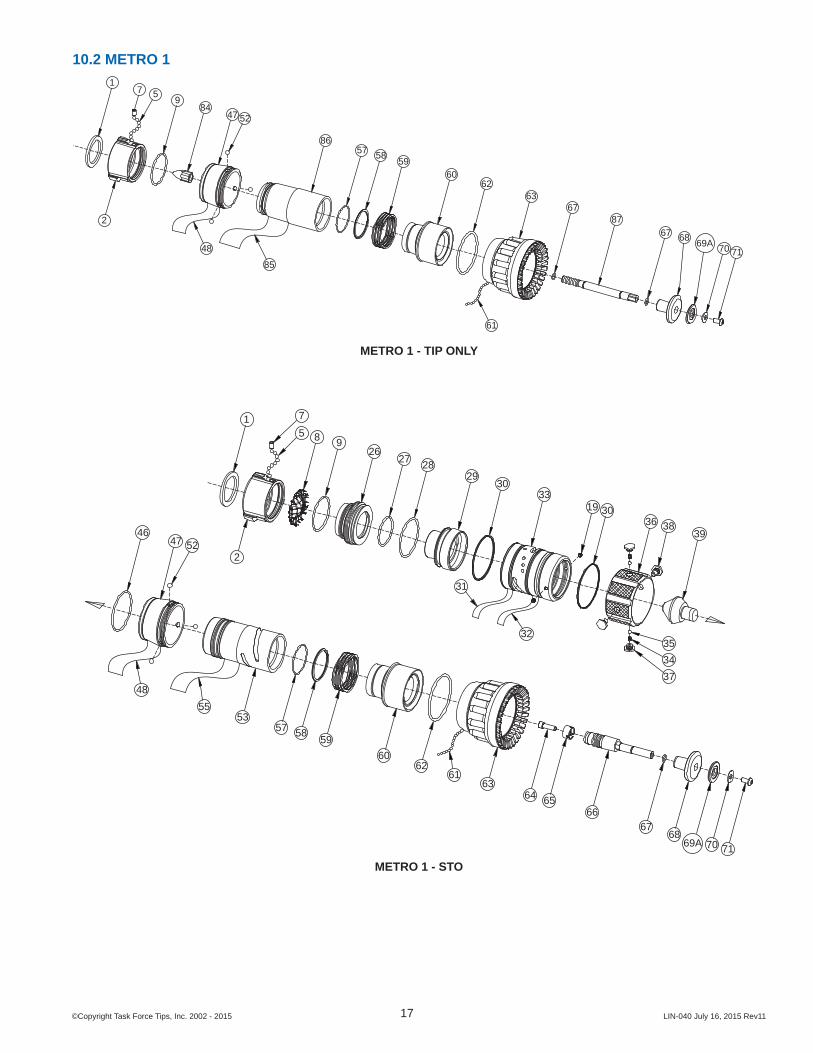
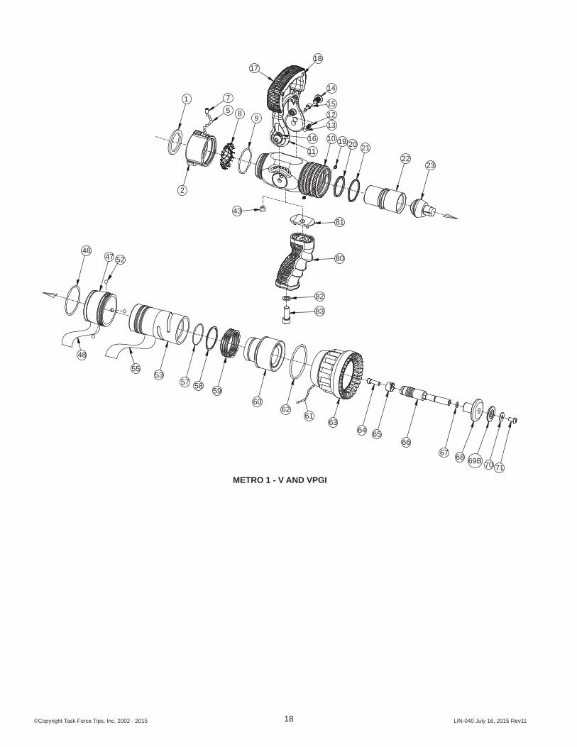
7.0 USE OF NOZZLES8.0 APPROVALS9.0 COLOR CODED VALVE HANDLE AND PISTOL GRIP 9.1 IMPULSE TRIGGER VALVE SYSTEM COLORED PISTOL GRIPS10.0 DRAWINGS AND PART LISTS 10.1 METRO 0 10.2 METRO 1 10.3 METRO 2 10.4 IMPULSE TRIGGER VALVE 10.5 IMPULSE GRIP11.0 WARRANTY12.0 MAINTENANCE 12.1 FIELD LUBRICATION 12.2 IMPULSE TRIGGER VALVE LUBRICATION 12.3 SERVICE TESTING 12.3.1 HYDROSTATIC TESTING 12.3.2 FLOW TESTING 12.3.3 RECORDS 12.4 REPAIR 13.0 OPERATION and INSPECTION CHECKLIST
DANGERPERSONAL RESPONSIBILITY CODE
The member companies of FEMSA that provide emergency response equipment and services want responders to know and understand the following:1. Firefi ghting and Emergency Response are inherently dangerous activities
requiring proper training in their hazards and the use of extreme caution at all times.
2. It is your responsibility to read and understand any user’s instructions, including purpose and limitations, provided with any piece of equipment you may be called upon to use.
3. It is your responsibility to know that you have been properly trained in Firefi ghting and /or Emergency Response and in the use, precautions, and care of any equipment you may be called upon to use.
4. It is your responsibility to be in proper physical condition and to maintain the personal skill level required to operate any equipment you may be called upon to use.
5. It is your responsibility to know that your equipment is in operable condition and has been maintained in accordance with the manufacturer’s instructions.
6. Failure to follow these guidelines may result in death, burns or other severe injury.
FEMSA Fire and Emergency Manufacturers and Service AssociationP.O. Box 147, Lynnfi eld, MA 01940 • www.FEMSA.org
1.0 MEANING OF SAFETY SIGNAL WORDSA safety related message is identifi ed by a safety alert symbol and a signal word to indicate the level of risk involved with a particular hazard. Per ANSI standard Z535.6-2011, the defi nitions of the four signal words are as follows:
DANGERDANGER indicates a hazardous situation which, if not avoided, will result in death or serious injury.
WARNINGWARNING indicates a hazardous situation which, if not avoided, could result in death or serious injury.
CAUTIONCAUTION indicates a potentially hazardous situation which, if not avoided, could result in minor or moderate injury.
NOTICENOTICE is used to address practices not related to personal injury.
SAFETY INSTRUCTIONS (or equivalent) signs indicate specifi c safety-related instructions of procedures.
2.0 SAFETY
DANGERAn inadequate supply of nozzle pressure and/or fl ow will cause an ineffective stream and can result in injury, death, or loss of property. See fl ow graphs or call 800-348-2686 for assistance.
WARNINGThe nozzle may be damaged if frozen while containing signifi cant amounts of water. Such damage may be diffi cult to detect visually and can lead to possible injury or death. Any time the nozzle is subject to possible damage due to freezing, it must be tested by qualifi ed personnel before being considered safe for use.
WARNINGThis equipment is intended for use by trained personnel for fi refi ghting. Their use for other purposes may involve hazards not addressed by this manual. Seek appropriate guidance and training to reduce risk of injury.
WARNINGFailure to restrain nozzle reaction can cause fi refi ghter injury from loss of footing and/or stream protection. Nozzle reaction will vary as supply conditions change: such as opening or closing other nozzles, hose line kinks, changes in pump settings, etc. Changes in spray pattern or fl ushing will also affect nozzle reaction. The nozzle operator must always be prepared in the event of these changes.
WARNINGIf nozzle gets out of control or away from operator, retreat from nozzle immediately. Do not attempt to regain control of nozzle while fl owing water. Injury from whipping can occur.
WARNINGWater is a conductor of electricity. Application of water on high voltage equipment can cause injury or death by electrocution. The amount of current that may be carried back to the nozzle will depend on the following factors:• Voltage of the line or equipment• Distance from the nozzle to the line or equipment• Size of the stream• Whether the stream is solid or broken• Purity of the water1
1 The Fire Fighter and Electrical Equipment, The University of Michigan Extension Service, Fourth Printing 1983. Page 47.
CAUTIONFire streams are capable of injury and damage. Do not direct water stream to cause injury or damage to persons or property.
3.0 GENERAL INFORMATIONThe Task Force Tips nozzles are designed to provide excellent performance under most fi refi ghting conditions. Their rugged construction is compatible with the use of fresh water as well as fi refi ghting foam solutions.
SERIES RECOMMENDEDMIN HOSE DIA.
FLOW SETTINGS NOZZLE TYPE
METRO 0(small body)
3/4”19 mm
Field ChangeableTo Any of 7 Sizes
Fixed Flow
METRO 1(small body)
1-1/238 mm
Field ChangeableTo Any of 14 Sizes
Fixed Flow
METRO 2(large body)
1-1/2 to 2-1/238 mm
Field ChangeableTo Any of 10 Sizes
Fixed Flow
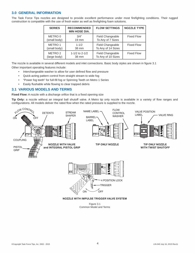
The nozzle is available in several different models and inlet connections. Basic body styles are shown in fi gure 3.1Other important operating features include:
• Interchangeable washer to allow for user defi ned fl ow and pressure• Quick-acting pattern control from straight stream to wide fog• “Power fog teeth” for full-fi ll fog or Spinning Teeth on Metro 1 Series• Easily fl ushable while fl owing to clear trapped debris
3.1 VARIOUS MODELS AND TERMSFixed Flow: A nozzle with a discharge orifi ce that is a fi xed opening size
Tip Only: a nozzle without an integral ball shutoff valve. A Metro tip only nozzle is available in a variety of fl ow ranges and confi gurations. All models deliver the rated fl ow when the rated pressure is supplied to the nozzle.
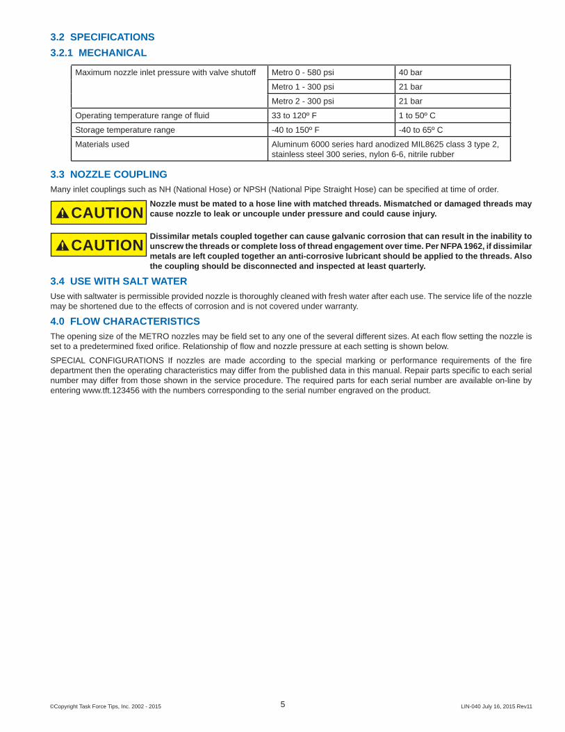
Maximum nozzle inlet pressure with valve shutoff Metro 0 - 580 psi 40 bar
Metro 1 - 300 psi 21 bar
Metro 2 - 300 psi 21 bar
Operating temperature range of fl uid 33 to 120º F 1 to 50º C
Storage temperature range -40 to 150º F -40 to 65º C
Materials used Aluminum 6000 series hard anodized MIL8625 class 3 type 2, stainless steel 300 series, nylon 6-6, nitrile rubber
3.3 NOZZLE COUPLINGMany inlet couplings such as NH (National Hose) or NPSH (National Pipe Straight Hose) can be specifi ed at time of order.
CAUTIONNozzle must be mated to a hose line with matched threads. Mismatched or damaged threads may cause nozzle to leak or uncouple under pressure and could cause injury.
CAUTIONDissimilar metals coupled together can cause galvanic corrosion that can result in the inability to unscrew the threads or complete loss of thread engagement over time. Per NFPA 1962, if dissimilar metals are left coupled together an anti-corrosive lubricant should be applied to the threads. Also the coupling should be disconnected and inspected at least quarterly.
3.4 USE WITH SALT WATERUse with saltwater is permissible provided nozzle is thoroughly cleaned with fresh water after each use. The service life of the nozzle may be shortened due to the effects of corrosion and is not covered under warranty.
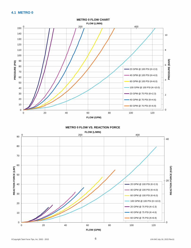
4.0 FLOW CHARACTERISTICSThe opening size of the METRO nozzles may be fi eld set to any one of the several different sizes. At each fl ow setting the nozzle is set to a predetermined fi xed orifi ce. Relationship of fl ow and nozzle pressure at each setting is shown below.
SPECIAL CONFIGURATIONS If nozzles are made according to the special marking or performance requirements of the fi re department then the operating characteristics may differ from the published data in this manual. Repair parts specifi c to each serial number may differ from those shown in the service procedure. The required parts for each serial number are available on-line by entering www.tft.123456 with the numbers corresponding to the serial number engraved on the product.
4.4 FLOW SETTINGThe washers are marked with various fl ow settings. Change washer to the desired setting. The nozzle will fl ow the indicated amount when the pressure at the nozzle is at the indicated level.To change fl ow and pressure setting of the Metro, use the following instructions:1) Set nozzle into FLUSH.2) Push baffl e down to barrel cone.3) Remove screw and washer using a 5/32 hex key.4) Remove pre-set fl ow washer and slide desired fl ow washer onto
shaft, desired fl ow marking facing up.5) Thread screw with washer back into shaft until snug (Do not over
tighten).NOTE: Metro 0, 1 and 2 series fl ow washers are not interchangeable
SCREWVT25Y28BH500METRO 0, 1 & 2
WASHERVW687X281-50METRO 0, 1 & 2
SHAFTB470 - METRO 0HM470 - METRO 1HX470 - METRO 2HX370 - METRO 1 TIP ONLY
BAFFLE
B461 - METRO 0HM461 - METRO 1H461 - METRO 2
FLOW WASHERB410 - METRO 0HM410-** METRO 1HX410-** METRO 2HM330-** METRO 1 TIP ONLY
WARNINGFailure to secure screw and washer will result in the baffl e becoming loose. This will produce poor stream, improper fl ows and possible discharge of the complete baffl e, resulting in risk of injury.
5.0 NOZZLE CONTROLSNozzle control valves must be opened slowly to eliminate unnecessary strain on the hose and couplings and reduce pressure surges.
5.1 FLOW CONTROL5.1.1 LEVER TYPE FLOW CONTROLOn models that use a lever type valve handle, the nozzle is shut off when the handle is fully forward. The valve handle has detented fl ow positions. These detent positions allow the nozzle operator to regulate the fl ow of the nozzle depending on the need or what can be safely and effectively handled. TFT recommends the use of a pistol grip for easier handling. For additional stress reduction, a hose rope or strap may also be used. This permits more effective use and ease of advancement, while minimizing strain and fatigue.
Nozzles attached to an in-service hose shall be stored in the off position.
ON
FLOW
CONTROL
OFF
5.1.2 TIP ONLY NOZZLESTip only nozzles have NO shut-off valve within the nozzle and MUST be used with a separate ball valve attached to the nozzle. Using a nozzle without a shutoff is an unsafe practice and should never be done.
5.1.3 BALL VALVE SHUTOFFA separate ball valve for use with Tip Only nozzles is shut off when the valve handle is fully forward. Pulling back on the handle opens the valve. Open valve slowly to avoid sudden changes in nozzle reaction. Close valve slowly to prevent water hammer. Note: In partially open positions a ball valve will cause turbulence and adversely affect stream quality.
Nozzles attached to an in-service hose shall be stored in the off position.
The notch in the ballis designed to reduceturbulence through apartially opened valveand does not affect shutoff.
5.1.4 TWIST SHUTOFF
On models that use a twist fl ow control, the valve is opened or closed by rotating the valve ring. Rotating the ring clockwise (as seen from the operating position behind the nozzle) closes the valve, while counterclockwise rotation opens it. Detents are provided at four intermediate positions and the position of the valve is shown by the exposed valve position label.
Nozzles attached to an in-service hose shall be stored in the off position. VALVE
POSITIONLABEL
VALVE RING
FLOW PATTERN LABEL
5.1.5 IMPULSE TRIGGER FLOW CONTROL
NOTE: THE TRIGGER RETURNS TO OFF IF NOT HELD OR LOCKED
OFFON
TRIGGER
LOCK
WARNINGDo not intentionally release the nozzle while fl owing and trust the valve to shut off automatically. The trigger nozzle’s ability to shut off by itself represents an extra level of safety when following normal nozzle handling procedures. To rely on it as the sole means of safety increases the risk of injury from an out of control nozzle. Release nozzle when fl ow has stopped.
5.1.5.1 IMPULSE TRIGGER LOCK
Use an 1/8” (3mm) punch to push out pin and remove lock if the lock is not desired.
LOCK
TRIGGER
LOCK PIVOT PIN
To Lock: Push on the lock while pulling back the trigger to engage one of the four locked positions.
To Release: Pull back slightly on trigger without any pressure on the lock. The spring loaded lock should automatically move to the unlocked position.
WARNINGWhen the trigger lock is engaged, the nozzle will not shut off if dropped. Always shut off nozzle before releasing the pistol grip to avoid injury from an out of control nozzle.
5.1.5.2 TRIGGER FLOW CONTROL SPEED ADJUSTMENTThe IMPULSE valve contains a slow close mechanism to prevent the nozzle from slamming off if the trigger is suddenly released. The closing speed is set at the factory to be slow enough to reduce water hammer, (“water hammer” is always present in any valve when it is shut off. The slow close mechanism will reduce this but cannot eliminate it completely) but fast enough to reduce the potential danger of hose whipping from a dropped nozzle. The closing speed may be adjusted as shown in the fi gure.5.1.5.2.
SlowerClose
FasterClose
Figure 5.1.5.2
Do not unscrew the adjuster past the end of the hand grip (to unscrew it too far could result in the loss of dampening fl uid.)
WARNINGA fl owing nozzle can cause injury within the fi rst second of lost control. As the closing time is increased so does the risk of injury from an out of control nozzle. Use caution when adjusting the closing speed and always verify performance after adjustment.
5.1.5.3 NORMAL OPERATING POSITION
45°
15°
90°
45°
Horizontal
Slow Closer Operating Range
Slow Closer Operating Range
WARNINGThe Slow Close Feature relies on a fl uid and air combination in the pistol grip. For proper function, the pistol grip should be within its normal operating position. The normal operating position is with the nozzle horizontal or pointing up with the pistol grip within 45 degrees of vertical. Releasing the trigger suddenly outside of the normal orientation will likely result in faster shut-off causing a higher pressure spike and increasing the risk of a burst hose. Do not suddenly release the trigger when operating outside of the nozzle’s normal orientation.
5.2 PATTERN AND FLUSH CONTROL5.2.1 PATTERN CONTROLTFT’s nozzles have full pattern control from straight stream to wide fog. Turning the stream shaper clockwise (as seen from the operating position behind the nozzle) moves the shaper to the straight stream position. Turning the shaper counterclockwise will result in an increasingly wider pattern.
Since the stream trim point varies with fl ow, the stream should be “trimmed” after changing the fl ow to obtain the straightest and farthest reaching stream. To properly trim the stream, fi rst open the pattern to narrow fog. Then close the stream to parallel to give maximum reach. Note: Turning the shaper further forward will cause stream crossover and reduce the effective reach of the nozzle.The nozzle reaction is greatest when the shaper is in the straight stream position. The nozzle operator must be prepared for a change in reaction as the pattern is changed.
5.2.2 FLUSH CONTROLSmall debris passes through the debris screen (if equipped) and may get caught inside the nozzle. This trapped material will cause poor stream quality, shortened reach, and reduced fl ow. To remove small debris, the nozzle may be fl ushed as follows:
• While still fl owing water, rotate the SHAPER counterclockwise (as viewed from behind the nozzle) to the fl ush position. (increased resistance will be felt on the SHAPER or RING as the nozzle goes into fl ush) This will open the nozzle allowing debris to pass through.
• During fl ush the nozzle reaction will decrease as the pattern becomes wider and the pressure drops. The nozzle operator must be prepared for an increase of nozzle reaction when returning the nozzle from the fl ush position to retain control of the nozzle.
• Rotate the SHAPER out of fl ush to continue normal operations.
WARNINGLarge amounts or pieces of debris may be unfl ushable and can reduce the fl ow of the nozzle resulting in an ineffective fl ow. In the event of a blockage, it may be necessary to retreat to a safe area, uncouple the nozzle and remove debris.
6.0 USE WITH FOAMThe nozzle may be used with foam solutions. Refer to fi re service training for the proper use of foam.
WARNINGFor Class B fi res, lack of foam or interruption in the foam stream can cause a break in the foam blanket and greatly increase the risk of injury or death. Assure that:
• Application rate is suffi cient (see NFPA 11 or foam manufacturer’s recommendations)• Enough concentrate is on hand to complete task (see NFPA for minimum duration time
requirements)• Foam logistics have been carefully planned.
Allow for such things as:• Storage of foam in a location not exposed to the hazard it protects• Personnel, equipment and technique to deliver foam at a rapid enough rate• Removal of empty foam containers • Clear path to deliver foam, as hoses and other equipment and vehicles are deployed
WARNINGImproper use of foam can result in injury or damage to the environment. Follow foam manufacturer’s instructions and fi re service training to avoid:
• Using wrong type of foam on a fi re, i.e. Class A foam on a Class B fi re• Plunging foam into pools of burning liquid fuels• Causing environmental damage• Directing stream at personnel
WARNINGThere are a wide variety of foam concentrates. Each user is responsible for verifying that any foam concentrate chosen to be used with this unit has been tested to assure that the foam obtained is suitable for the purpose intended.
WARNINGUse of compressed air foam (CAF) with hand held nozzles can cause sudden surges in nozzle reaction force resulting in risk of injury or death from loss of footing or hose whipping. Be prepared for sudden changes in nozzle reaction caused by:
• Slug loading (Loss of foam concentrate sends slugs of air and water into the nozzle)• Sudden release of built-up pressure in the hose when opening a nozzle
6.1 FOAM ASPIRATING ATTACHMENTSMulti-expansion or low expansion aspirating attachments may be used with nozzles to increase the expansion ratio. These foam tubes attach and detach quickly from the nozzle. As expansion ratio is increased, the reach of the nozzle will be decreased due to the greater amount of bubbles in the stream and their ability to penetrate the air. Generally the straight stream reach with foam is approximately 10% less than with water only. Actual results will vary based on brand of foam, hardness of water, temperature, etc. For specifi c information, see LIA-025 (MANUAL: Foam Attachments for TFT Nozzles).
7.0 USE OF NOZZLESMany factors contribute to the extinguishment of a fi re. Among the most important is delivering water at a fl ow rate suffi cient to absorb heat faster than it is being generated. The fl ow rate depends largely on the pump discharge pressure and hose friction loss. It can be calculated using a hydraulic equation such as:
PDP = NP + FL + DL + EL
PDP = Pump discharge pressure in PSINP = Nozzle pressure in PSIFL = Hose friction loss in PSIDL = Device loss in PSIEL = Elevation loss in PSI
This manual is not intended to act as a training guide for safe fi reground tactics and operations. For additional information visit www/tft.com or contact customer service at 800-348-2686.
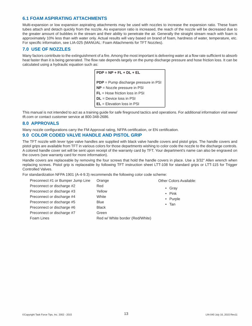
8.0 APPROVALSMany nozzle confi gurations carry the FM Approval rating, NFPA certifi cation, or EN certifi cation.9.0 COLOR CODED VALVE HANDLE AND PISTOL GRIPThe TFT nozzle with lever type valve handles are supplied with black valve handle covers and pistol grips. The handle covers and pistol grips are available from TFT in various colors for those departments wishing to color code the nozzle to the discharge controls. A colored handle cover set will be sent upon receipt of the warranty card by TFT. Your department’s name can also be engraved on the covers (see warranty card for more information).Handle covers are replaceable by removing the four screws that hold the handle covers in place. Use a 3/32” Allen wrench when replacing screws. Pistol grip is replaceable by following TFT instruction sheet LTT-108 for standard grips or LTT-115 for Trigger Controlled Valves.For standardization NFPA 1901 (A-4-9.3) recommends the following color code scheme:
Preconnect #1 or Bumper Jump LinePreconnect or discharge #2 Preconnect or discharge #3 Preconnect or discharge #4 Preconnect or discharge #5 Preconnect or discharge #6 Preconnect or discharge #7 Foam Lines
OrangeRedYellowWhiteBlueBlackGreenRed w/ White border (Red/White)
9.1 IMPULSE TRIGGER VALVE SYSTEM NOZZLE COLORED PISTOL GRIPSThe TFT Impulse Trigger Valve System nozzles are supplied with black pistol grip covers. The pistol grip covers are available from TFT in various colors for those departments wishing to color code the nozzle to the discharge controls. Follow the steps below to change the pistol grip cover.
Pistol Grip Cover(TN691-BLK)
Cap (TN103)(1/2 in square drive)
Adjusting Screw (TN102)(3/16 in Allen Wrench)
1) Orient nozzle vertically. This keeps the dampening fl uid in the pistol grip from spilling out.2) Remove the Cap. (1/2 in square drive) The Adjusting Screw (3/16 in Allen Wrench) may need to be turned in or removed to be
able to engage the square pocket in the cap. Note the position of the Adjusting Screw before moving it.3) Slide off the Pistol Grip Cover and install a new one. Be sure the Pistol Grip Cover’s internal rib is toward the back of the
nozzle.4) Reinstall the Cap until it bottoms out on its shoulder.5) Reinstall or reposition the Adjusting Screw if it has been moved from its original location.6) Flow nozzle to check performance of slow closer. Adjust as needed (see section 5.1.5.2).
11.0 WARRANTYTask Force Tips, Inc., 3701 Innovation Way, Valparaiso, Indiana 46383-9327 USA (“TFT”) warrants to the original purchaser of its nozzles (“equipment”), and to anyone to whom it is transferred, that the equipment shall be free from defects in material and workmanship during the fi ve (5) year period from the date of purchase.TFT’s obligation under this warranty is specifi cally limited to replacing or repairing the equipment (or its parts) which are shown by TFT’s examination to be in a defective condition attributable to TFT. To qualify for this limited warranty, the claimant must return the equipment to TFT, at 3701 Innovation Way, Valparaiso, Indiana 46383-9327 USA, within a reasonable time after discovery of the defect. TFT will examine the equipment. If TFT determines that there is a defect attributable to it, TFT will correct the problem within a reasonable time. If the equipment is covered by this limited warranty, TFT will assume the expenses of repair.If any defect attributable to TFT under this limited warranty cannot be reasonably cured by repair or replacement, TFT may elect to refund the purchase price of the equipment, less reasonable depreciation, in complete discharge of its obligations under this limited warranty. If TFT makes this election, claimant shall return the equipment to TFT free and clear of any liens and encumbrances.This is a limited warranty. The original purchaser of the equipment, any person to whom it is transferred, and any person who is an intended or unintended benefi ciary of the equipment, shall not be entitled to recover from TFT any consequential or incidental damages for injury to person and/or property resulting from any defective equipment manufactured or assembled by TFT. It is agreed and understood that the price stated for the equipment is in part consideration for limiting TFT’s liability. Some states do not allow the exclusion or limitation of incidental or consequential damages, so the above may not apply to you.TFT shall have no obligation under this limited warranty if the equipment is, or has been, misused or neglected (including failure to provide reasonable maintenance) or if there have been accidents to the equipment or if it has been repaired or altered by someone else.THIS IS A LIMITED EXPRESS WARRANTY ONLY. TFT EXPRESSLY DISCLAIMS WITH RESPECT TO THE EQUIPMENT ALL IMPLIED WARRANTIES OF MERCHANTABILITY AND ALL IMPLIED WARRANTIES OF FITNESS FOR A PARTICULAR PURPOSE. THERE IS NO WARRANTY OF ANY NATURE MADE BY TFT BEYOND THAT STATED IN THIS DOCUMENT.This limited warranty gives you specifi c legal rights, and you may also have other rights which vary from state to state.
12.0 MAINTENANCETFT nozzles are designed and manufactured to be damage resistant and require minimal maintenance. However, as the primary fi refi ghting tool upon which your life depends, it should be treated accordingly. Do not drop or throw equipment.
12.1 FIELD LUBRICATIONAll Task Force Tip nozzles are factory lubricated with high quality silicone grease. This lubricant has excellent washout resistance and long term performance. If your department has unusually hard or sandy water, the moving parts may be affected. Foam agents and water additives contain soaps and chemicals that may break down the factory lubrication.
The moving parts of the nozzle should be checked on a regular basis for smooth and free operation, and signs of damage. IF THE NOZZLE IS OPERATING CORRECTLY, THEN NO ADDITIONAL LUBRICATION IS NEEDED. Any nozzle that is not operating correctly should be immediately removed from service.
The fi eld use of Break Free CLP (spray or liquid) lubricant will help to restore the smooth and free operation of the nozzle. However, these lubricants do not have the washout resistance and long-term performance of the silicone grease. Therefore, re-application of Break Free CLP will be needed on a regular basis. CAUTION: Aerosol lubricants contain solvents that can swell O-Rings if applied in excess. The swelling can inhibit smooth operation of the moving parts. When used in moderation, as directed, the solvents quickly evaporate without adversely swelling the O-Rings.
The nozzle can be returned to the factory for a complete checkup and re-lubrication with silicone grease
PART ONE — COUPLING DOWNPosition the nozzle at a 45-degree angle with the COUPLING end down. CLOSE the valve handle and set the pattern to STRAIGHT STREAM. Then spray a short burst into these areas: #1 FRONT PATTERN CONTROL SEAL Spray in between the pattern control and the barrel.#2 PRESSURE CONTROL UNITPlace check sticks behind baffl e while shaper is in fl ush. Cycle baffl e in and out using check sticks several times to work lubrication into o-rings. #3 FRONT SLIDER SEALa) Rotate shaper into FLUSH position.b) Spray down the front end of the nozzle to dribble lubricant into the clearances between the shaper and the valve body.
While holding nozzle at the angle, wait 30 seconds for the lubricant to penetrate into the clearances. Cycle the valve handle and rotate the shaper from straight stream to full fl ush several times, and then proceed to the next section.
PART TWO — COUPLING UPPosition the nozzle at a 45-degree angle with the BUMPER end down. OPEN the valve handle and set the pattern to FLUSH. Spray a short burst in these areas: #4 REAR SHAPER SEAL Spray down the clearance between the label and the shaper guide.#5 REAR SLIDER SEAL Spray into the clearance between the slider and the valve body.#6 FLUSH MECHANISM SEALa) With the handle on the top, spray down into the nozzle. The aerosol extension tip will help direct the spray into clearances leading to the O-Ring.b) Rotate nozzle so the valve is on the bottom and spray another short burst.#7 DETENTS IN THE HANDLE Spray a small amount on the detent followers located in the handle.
While holding nozzle at the angle, wait 30 seconds, then cycle the valve handle several times. Rotate the pattern control from straight stream to full fl ush several times. The pattern control should move freely and easily. The barrel cone should move forward to within 1/16” of the baffl e before the shaper reaches straight stream position. Wipe off excess lubricant.
IF THIS PROCEDURE DOES NOT RESTORE SMOOTH AND FREE OPERATION OF ALL THE MOVING PARTS, THEN FACTORY SERVICE IS NEEDED. • 24-HOUR HOT LINE — 800-348-2686 • www.tft.com
12.2 IMPULSE TRIGGER VALVE LUBRICATION1) Insert tube from BreakFree into drain
hole in pistol grip.
2) With nozzle upside down spray a 2 second burst into the pistol grip.Holding a rag around the tube here can help keep excess BreakFree from the outside of the nozzle.
3) Keep nozzle upside down for at least 10 seconds to allow the BreakFree to fl ow into the valve area.
4) Check for smooth and free operation of the trigger. Repeat a second time if needed.
Holding a rag around the tube herecan help keep excess BreakFreefrom the outside of the nozzle.
If this procedure does not restore trigger operation then factory service is needed. 24 hour Technical Service and Support - 800-348-2686 - www.tft.com
12.3 SERVICE TESTINGIn accordance with NFPA 1962 (2013), nozzles must be tested a minimum of annually. Nozzles failing any part of this test must be removed from service, repaired and retested upon completion of the repair.
12.3.1 HYDROSTATIC TESTINGEach nozzle with a shut off mechanism shall be tested in the following manner.
1. The nozzle shall be placed in a device capable of holding it and the shut off shall be closed.2. A device capable of exerting a hydrostatic pressure of 300 psi (2070 kPa) or 1.5 times the maximum operating pressure,
whichever is higher, shall be attached to the nozzle.3. All air shall be bled from the system.4. The gage pressure shall be increased by 50 psi (3.5 bar or 345 kPa) increments, held for 30 seconds at each pressure up to
the maximum pressure for which the nozzle is being tested, and then held for one minute without leakage.5. There shall be no sign of leakage through the valve or shut off.
12.3.2 FLOW TESTINGFlow testing must be conducted in the following manner.
1. The nozzle shall be mounted so that the fl ow rate and pressure through the nozzle and the pressure at the inlet can be accurately measured.
2. With the shut off fully open, the inlet pressure shall be adjusted to the rated pressure ±2 percent.3. The valve or shut off and pattern controls shall be operated through their full range of motion at 100 psi (6.9 bar or 690 kPa)
with no signs of leaking, binding or other problems.4. Evaluate the fl ow of nozzles as defi ned by NFPA 1964 in the following manner:
Automatic (Constant Pressure) Spray Nozzles1. The fl ow rate shall slowly be increased to the maximum rated fl ow, and the minimum and maximum pressures through
the fl ow range recorded.2. Nozzles shall maintain their rated pressure ±15 psi (±1 bar or ±100 kPa) throughout the rated fl ow range.
12.3.3 RECORDSA record of testing and repairs must be maintained from the time the nozzle is purchased until it is discarded. Each TFT nozzle is engraved with a unique serial number which, if so desired, can be used to identify nozzle for documentation purposes.The following information, if applicable, must be included on the test record for each nozzle:
1. Assigned identifi cation number2. Manufacturer3. Product or model designation4. Vendor5. Warranty6. Hose connection size7. Maximum operating pressure8. Flow rate or range9. Date received and date put in service10. Date of each service test and service test results11. Damage and repairs, including who made the repairs and the cost of repair parts12. Reason removed from service
NFPA 1962: Standard for the care, use, inspection, service testing, and replacement of fi re hose, couplings, nozzles and fi re hose appliances. (2013 ed., Section 5.5.4). Quincy, MA: National Fire Protection Agency.
12.4 REPAIRFactory service is available with repair time seldom exceeding one day in our facility. Factory-serviced nozzles are repaired by experienced technicians, wet tested to original specifi cations, and promptly returned. Repair charges for non-warranty items are minimal. Any returns should include a note as to the nature of the problem and whom to reach in case of questions.Repair parts and service procedures are available for those wishing to perform their own repairs. Task Force Tips assumes no liability for damage to equipment or injury to personnel that is a result of user service. Contact the factory or visit the web site at www.tft.com for parts lists, exploded views, test procedures and troubleshooting guides.Performance tests shall be conducted on the nozzle after a repair, or anytime a problem is reported to verify operation in accordance with TFT test procedures. Consult factory for the procedure that corresponds to the model and serial number of the nozzle. Any equipment which fails the related test criteria should be removed from service immediately. Troubleshooting guides are available with each test procedure or equipment can be returned to the factory for service and testing.
CAUTIONAny alterations to the nozzle and its markings could diminish safety and constitutes a misuse of this product.
13.0 OPERATION AND INSPECTION CHECKLISTBEFORE EACH USE the nozzle must be inspected to this checklist:
1) There is no obvious damage such as missing, broken or loose parts, corrosion, damaged labels etc.2) Debris screen is free of debris3) Coupling is tight and leak free4) Valve operates freely through full range and regulates fl ow5) “OFF” position does fully shut off and fl ow is stopped6) Nozzle fl ow is adequate as indicated by pump pressure and nozzle reaction7) Shaper turns freely and adjusts pattern through full range8) Shaper turns into full fl ush and out of fl ush with normal fl ow and pressure restored
BEFORE BEING PLACED BACK IN SERVICE, nozzles must be inspected to this checklist;
1) All controls and adjustments are operational 2) Shut off valve (if so equipped) closes off the fl ow completely 3) There are no broken or missing parts 4) There is no damage to the nozzle 5) The thread gasket is in good condition 6) The waterway is clear of obstructions 7) Nozzle is clean and markings are legible 8) Coupling is retightened properly 9) Shaper is set to desired pattern10) Shutoff handle is stored in the OFF position
NFPA 1962: Standard for the care, use, inspection, service testing, and replacement of fi re hose, couplings, nozzles and fi re hose appliances. (2013 ed., Section 5.2.2). Quincy, MA: National Fire Protection Agency.
WARNINGAny nozzle failing any part of the checklist is unsafe for use and must have the problem corrected before use or being placed back into service. Operating a nozzle that has failed the checklist is a misuse of this equipment.