Page 1
AUTOMATIC BUTTON FEEDER
INSTALLATION / INSTRUCTION
MANUAL
MODEL
BM-737S
TEL : Tel : 82-2-432-6885 / Fax : 82-2-432-5877
E-MAIL : [email protected]
WEB-SITE : WWW.SEUNGILAUTO.CO.KR
IF YOU WANT TO GET MORE DETAILS, PLEASE CONTACT WITH US.
SEUNG IL APC
Page 2
< Installation >
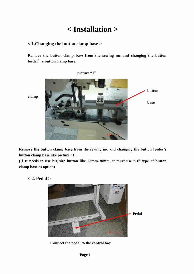
< 1.Changing the button clamp base >
Remove the button clamp base from the sewing mc and changing the button
feeder’s button clamp base.
picture “1”
button
clamp
base
Remove the button clamp base from the sewing mc and changing the button feeder’s
button clamp base like picture “1”.
(If It needs to use big size button like 23mm-30mm, it must use “B” type of button
clamp base as option)
< 2. Pedal >
Pedal
Connect the pedal to the control box.
Page 1
Page 3
< 3. Adjustment the center of the button >
Picture“3” Picture“3-1”
Nut
1) It must be adjusted the center of the button and Needle like picture “3”
If need, it can be adjusted using the Nut like picture “3-1”
< 3-1.Remove the cover >
Remove the Cover
Page 2
Page 4
< 4. Fix the Button feeder on the table >
1) Put the button feeder body on the table d rotate the dial(picture “4”)
2) Turn the dial(picture “4-8”
3) The pin plate must be located the center of the button clamp(picture “4-1”)
4) Mark 4-point of the table(picture “4-2”/”4-3”) and make a hole using drill.(7mm)
5) .Put the button feeder’s body again(picrure “4-5”)
6) Re-check the center of the button clamp with needle
7) Fix the nut
Picture “4” picture “4-1” picture “4-2”
Picture “4-3” picture “4-4” picture “4-5”
picture “4-6” picture “4-7” picture “4-8”
Page 3
Page 5
< 5. Adjustment the button clamp lift shaft >
It can be adjusted the height of the pin plate and bottom(picture “5-1”) about 10mm
Using button clamp lift shaft( picture “5” A) .
Picture “5” picture “5-1”
A B C About 10mm
“A” : Button clamp lift shaft
“C” : Roller shaft
.
< 6. Connect the cable >
Cable Cable
.
Page 4
Page 6
< 3. For control box / operation panel / connecting / switch box >
1)Fix the control box on the table.
(It can be fixed at any place for the operation panel of the sewing mc)
Put the hole of the control box.
2)Insert the connector of the button feeder follow’s same no.
C13 Cable
Using “Micro Switch” Connecting with Board for sewing mc
Connecting “C9” Cable Connecting “C13” Cable
3)Please connect the button feeder main power switch with switch box of sewing
mc.(The Green is Earth line.)
Green Color : earth line
Connecting the wire
Page 5
Page 7
< 4. Connecting the “C 13” Cable & “C9” Cable for the automatic
feeder signal >
1.Connecting ”C13”Cable : Without Using the Micro Switch ,Using connecting
the board of the sewing mc, Please connect the “C
13” Cable.(2-Hole)
“C 13”Cable
“C 13”Connector
(2-Hole)
Connecting the Board
Of Sewing Mc.
2.Connecting ”C9” Cable : When using the “Micro Switch”,( CHAIN or
BROTHER B438F) ,Using “C 9” cable(4-Hole)
“C 9”Cable
“C 9”Connector
(4-Hole)
Using Micro Switch
*If don’t have the “C 9” cable,It can use the “C13” cable for micro switch.But it
must be connect to the Right position of the connector.
“C13”Cable
“C9”connector(Using Right position)
Page 6
Page 8
< FOR BROTHER B438D >
Thread trimming
Solenoid
Connecting
Connecting the “C 13” cable of the button feeder with Thread trimming solenoid
cable from the sewing mc’s board.
< FOR BROTHER B438E >
Connecting the “C 13” cable
Thread trimming solenoid cable
Connecting the “C13” cable of the button feeder with Thread trimming
solenoid cable.
Page 7
Page 9
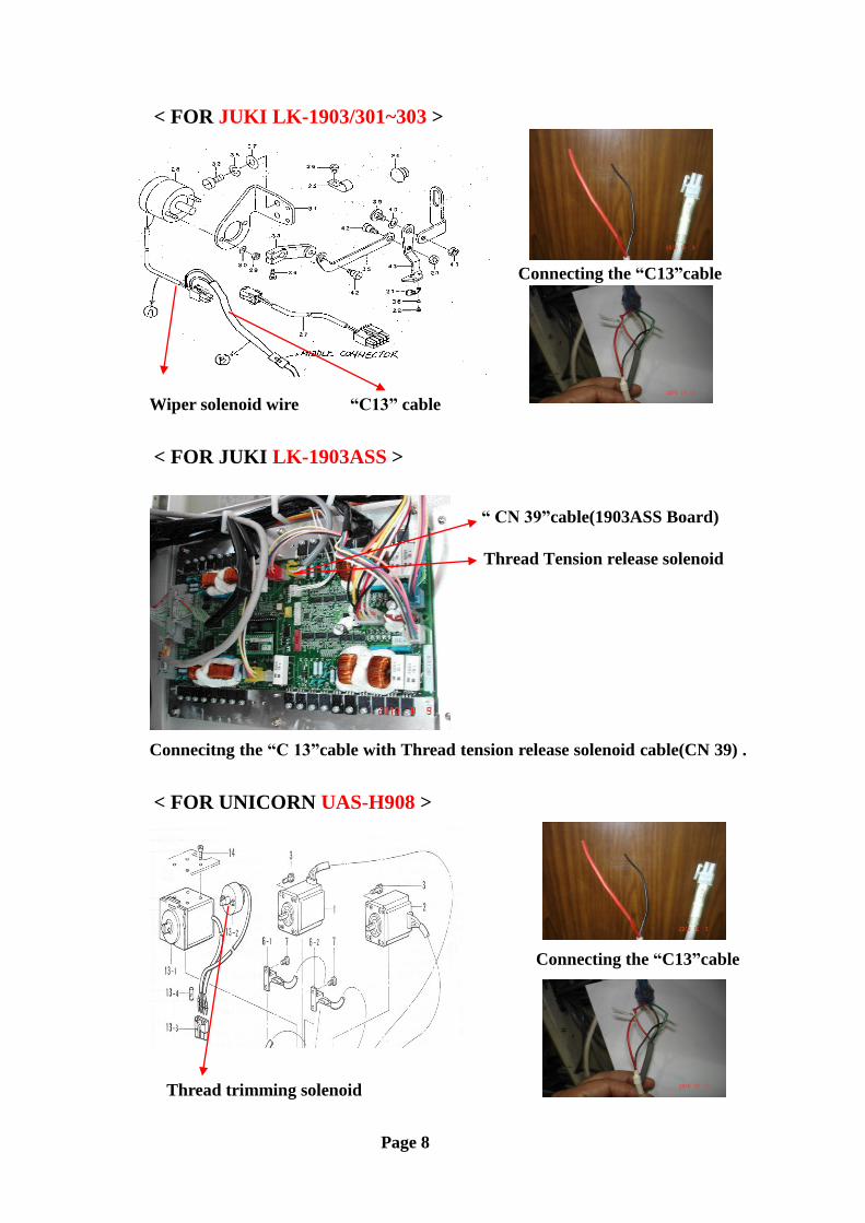
< FOR JUKI LK-1903/301~303 >
Connecting the “C13”cable
Wiper solenoid wire “C13” cable
< FOR JUKI LK-1903ASS >
“ CN 39”cable(1903ASS Board)
Thread Tension release solenoid
)
Connecitng the “C 13”cable with Thread tension release solenoid cable(CN 39) .
< FOR UNICORN UAS-H908 >
Connecting the “C13”cable
Thread trimming solenoid
Page 8
Page 10
< CONNECTING THE “C 9” CABLE USING FOR MICRO
SWITCH >
IF YOU ARE USING “MICRO SWITCH” FOR FEEDER SIGNAL, YOU MUST USE “C 9”
CABLE FROM THE BUTTON FEEDER( DON’T USE “C 13” CONNECTOR”! )
< FOR JUKI MB-373 OR 1377 > CHAINSTITCH
“C 9” CONNECTOR CONNECTING THE MICRO SWITCH ON THE HEAD
< FOR BROTHER B438F >
“C 9” CONNECTOR MICRO SWITCH INSTALL THE “MICRO SWITCH” THIS POSITION.
< Re-Connecting the “C 13” Cable >
A(RED COLOR)
B(BLACK COLOR)
C
D
(A & C / B & D)
First,try to connect the “C13” wire(Red/Black & A/B) with Sewing mc’s wire(C
& D) and then try to push the Manual button and press the pedal.If the button
feeder is not working when press the pedal, please Re-connect the “C 13” wire
for Opposite Direction ( A & D / B & C).
The “C13”cable has “ + & - “ so it must be tested after connecting the cable,If no
working, please Re-connect the “C 13” Cable to the opposite direction.
Page 9
Page 11
< Instruction Manual >
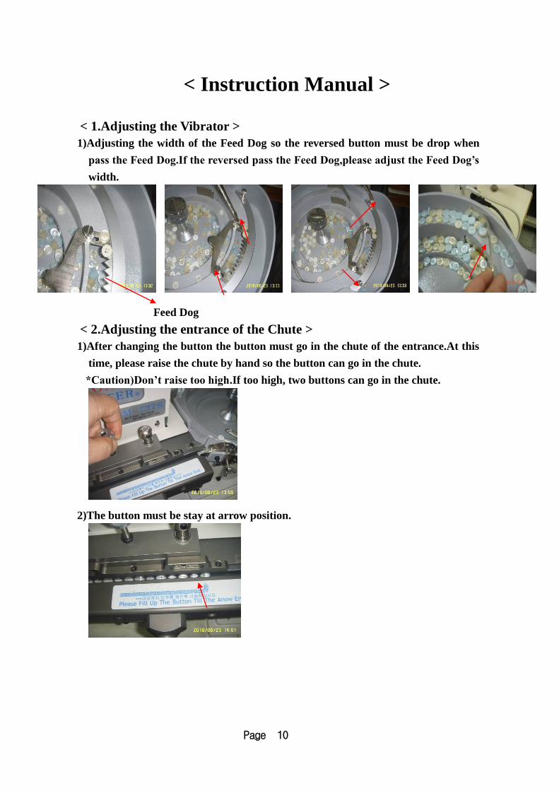
< 1.Adjusting the Vibrator >
1)Adjusting the width of the Feed Dog so the reversed button must be drop when
pass the Feed Dog.If the reversed pass the Feed Dog,please adjust the Feed Dog’s
width.
Feed Dog
< 2.Adjusting the entrance of the Chute >
1)After changing the button the button must go in the chute of the entrance.At this
time, please raise the chute by hand so the button can go in the chute.
*Caution)Don’t raise too high.If too high, two buttons can go in the chute.
2)The button must be stay at arrow position.
Page 10
Page 12
< 3.Adjusting the Width of the Chute and Tension >
1)After changing the button, it must be adjusted the width of the chute using the
dial.
2)If the width of the chute too wide, the button can be dropped and too narrow ,
the button can not supply to the pin plate.
After adjust the width of the chute, please re-check the width.
Gap(0.5-10mm)
2)Press the chute by hand and the chute must be going down very smoothly.If the
chute is too strong or weak,it can not supply the button to the pin plate.It can
adjust the tension of the chute using the dial.
Checking the
tension
Adjusting Dial
3)Re-install the front cover.
If they don’t have a Gap like picture, the chute can not work smoothly.
Gap.
Page 11
Page 13
< 4. Changing the Pin Plate >
1)Checking the Pin plate size when changing the new button
Please check the size of the pin plate with new button
Standard Size : 1.2mm/4-hole/2.8mm(Fixed in the mc).
A TYPE(1.0MM) 4-HOLE : 2.2MM
(1.2MM) 2HOLE/4-HOLE : 2.4MM/2.6MM/2.8MM/3.0MM/3.2MM/3.4MM
“B” TYPE(1.5MM) 2HOLE/4HOLE : 3.4MM/3.6MM/3.8MM/4.0MM/4.2MM/4.5MM(Option)
Turing the dial of the button feeder by hand and the pin please must be located at
the center of the Button clamp and the Button clamp base will going up 1-step
and 2-step.At the 2-step , it can pull the pin plate by hand and change the new
pin plate after checking the exact size of the pin plate with new button
Page 12
Page 14
< 5. Adjusting the rotating rubber >
It must be Gap about 0.2mm with pin plate when going down the rotating rubber.
< Adjusting the rotating rubber position >
First, Push the Auto/Manual Key (Located Manual) and then going down the
rotating rubber by hand and then can check the Gab.
Gap : 0.2mm
Caution)The rotating rubber must be going up(Original position)after pushing the
button to the pin plate.If the rotating rubber can not going up the original
position,it can see the “Error No 03” on the panel.
Rotating Rubber
3)Re-checking the size of the pin plate with button
- If the pin plate is small than button hole, the button can not put in the pin
plate.
4)Two buttons stay in the pin plate.
5)Solenoid problem – Oiling the behind of the solenoid
.
Rotating rubber Solenoid
Page 13
Page 15
6)Adjusting the rotating rubber position
Rotating rubber
adjusting screw
Turn off the sensor when going
Down the rotating rubber
Sensor
< 6. Changing the new button >
1)Remove the Vibrator using hand and pour the button and re-tighten the dial
by hand.
A B C
2)Or open the door to remove the button(Picture “C”)
< 7.Adjusting the Chute exit base plate >
1)If you need to adjust the position of the “Chute exit base plate”,you can use
the screw
Screw for “chute exit base plate”
Chute exit base plate
Page 14
Page 16
< 8. Turn off the power switch >
It must push the “Manual button” and using the button feeder when turn off
the sewing mc power.
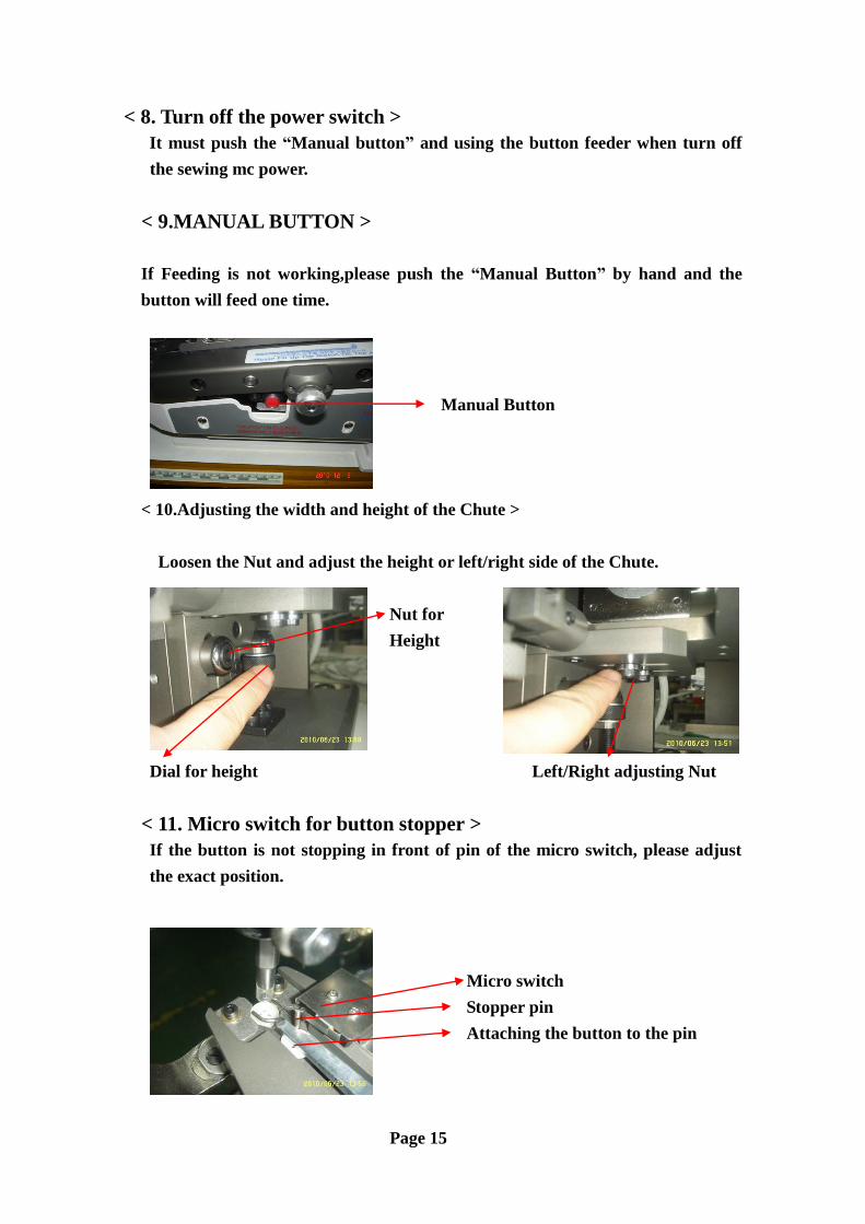
< 9.MANUAL BUTTON >
If Feeding is not working,please push the “Manual Button” by hand and the
button will feed one time.
Manual Button
< 10.Adjusting the width and height of the Chute >
Loosen the Nut and adjust the height or left/right side of the Chute.
Nut for
Height
Dial for height Left/Right adjusting Nut
< 11. Micro switch for button stopper >
If the button is not stopping in front of pin of the micro switch, please adjust
the exact position.
Micro switch
Stopper pin
Attaching the button to the pin
Page 15
Page 17
< 12.Adjusting the width of the button clamp >
Nut for button clamp Cable for button clamp width adjusting
< 13. Adjusting the Stopper >
A
Stopper
C
If it need to adjust the pin plate,it can be adjusted the stopper.
< 14.Static Electricity >
If it has “Static electricity from the button, it can use the flour on the vibrator.
<15.Missing the button on the Button clamp >
Checking the button clamp.
<16.Using BIG SIZE button(25-30mm) >
Changing the “B” type Button clamp base..
Page 16
Page 18
< 17.Operation Panel >
1 2 3 4 5 6 7 8 9 10
1.AUTO/MANUAL KEY : Using button feeder : “Auto”/ testing the mc “Manual”
2.CLEAR KEY : Make “0” no
3.DOWN KEY : Re-duce the No
4.CENTER OPEN KEY : Opening/Closing the Chute exit base plate
5.ROTATING RUBBER KEY : Operating the Rotating rubber
6.FORWARD KEY : forward Key
7.BACKWORD KEY : Remove the button from the Chute dial.
8.EMERGENCY KEY : Stop the button feeder
9.FEEDING SPEED KEY : Feeding speed adjusting key
10.VIBRATOR KEY : Vibrator Speed adjusting Key
Page 17
Page 19
썬스타 SPS/A-B1202 와 BM-737S 결합 순서
(Procedure of Connection Between SunStar SPS/A-B1202 And BM-737S)
** 초기 준비( Initial Preparation ) **
1) 재봉기 전원 OFF 상태에서 조작상자의 READY , RESET 를 동시에 누르고 전원 ON
(Turn On the Machine Power ON with Pushing READY & RESET Button Together )
2) A 누른다 (Push A )
3) 표시창에 A-01을 + 를 눌러서 A-14로 만든 다음 READY 누르고
(After Pushing + Button in The Operation Panel, Make A-01 be A-14 And Then)
0=와이퍼 OFF를 1= 와이퍼 ON으로 만든 다음 READY 을 누른다 ( Make 0= Wiper OFF, Make 1=Wiper ON And Then Push READY Button )
4) 표시창에 A-15로 가서 (노루발 상승속도) 0 =늦고, 1=빠르고 선택한 후 READY
( Control The Foot Lifting Speed 0=Low Speed , 1=High Speed In The Panel A-15 )
5) 표시창에 A-18로 가서 (와이퍼 속도) 40 적당함 READY
( Control Speed Of Wiper In The A-18 Panel. 40 Is Suitable )
* 컨넥터 칼라별 구분 : 백색 = 와이퍼
청색 = 사절
적색 = 누름판
* 백색 = 와이퍼에 공급기 신호선을 연결한다
Page 18
갈 –
백 +