Geomatica OrthoEngine V10.3 Tutorial Manual Mosaicking Manual mosaicking allows you to mosaic individual image files or edit unsatisfactory images and/or cutlines in files that were created using the automatic mosaicking tool. The following tutorial outlines the basic steps involved in mosaicking a series of orthorectified images using the new manual mosaic tool in OrthoEngine V10.3 1.0 Setting up the Project For the purpose of this tutorial, we will create a new OrthoEngine project using “None (Mosaic Only)” for the Math Modeling Method. This method can be used if you have a series of georeferenced images available. If your images are not georeferenced, you can orthorectify and manually mosaic the images by choosing a different OrthoEngine project type. To create a new project: 1. From the File menu on the OrthoEngine window, click New. The Project Information dialog box opens. 2. Click Browse and locate the appropriate folder 3. In the File name box, enter manual_mosaic.prj and click Open. 4. In the Name box, enter Mosaic Only Project. 5. In the Description box, enter a short description - “QuickBird mosaic project” 6. For the Math Modelling Method, select None (mosaic only). 7. Click OK. You will then need to set the projection for the project. 1
Transcript
Geomatica OrthoEngine V10.3 Tutorial Manual Mosaicking Manual mosaicking allows you to mosaic individual image files or edit unsatisfactory images and/or cutlines in files that were created using the automatic mosaicking tool. The following tutorial outlines the basic steps involved in mosaicking a series of orthorectified images using the new manual mosaic tool in OrthoEngine V10.3
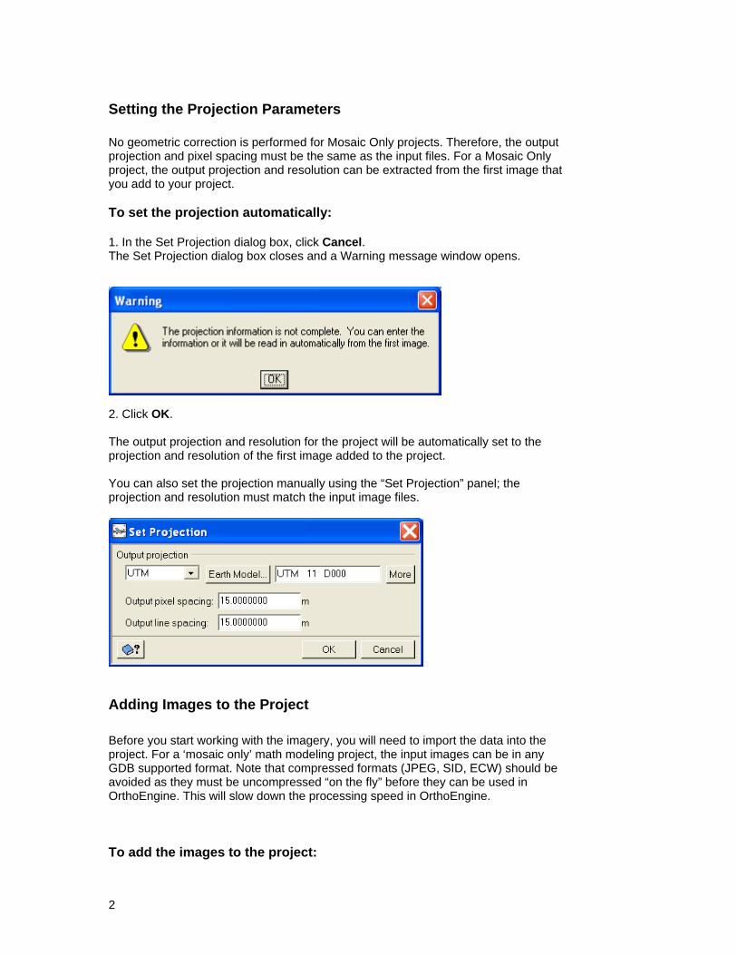
1.0 Setting up the Project For the purpose of this tutorial, we will create a new OrthoEngine project using “None (Mosaic Only)” for the Math Modeling Method. This method can be used if you have a series of georeferenced images available. If your images are not georeferenced, you can orthorectify and manually mosaic the images by choosing a different OrthoEngine project type. To create a new project: 1. From the File menu on the OrthoEngine window, click New.
The Project Information dialog box opens. 2. Click Browse and locate the appropriate folder 3. In the File name box, enter manual_mosaic.prj and click Open. 4. In the Name box, enter Mosaic Only Project. 5. In the Description box, enter a short description - “QuickBird mosaic project” 6. For the Math Modelling Method, select None (mosaic only).
7. Click OK. You will then need to set the projection for the project.
1
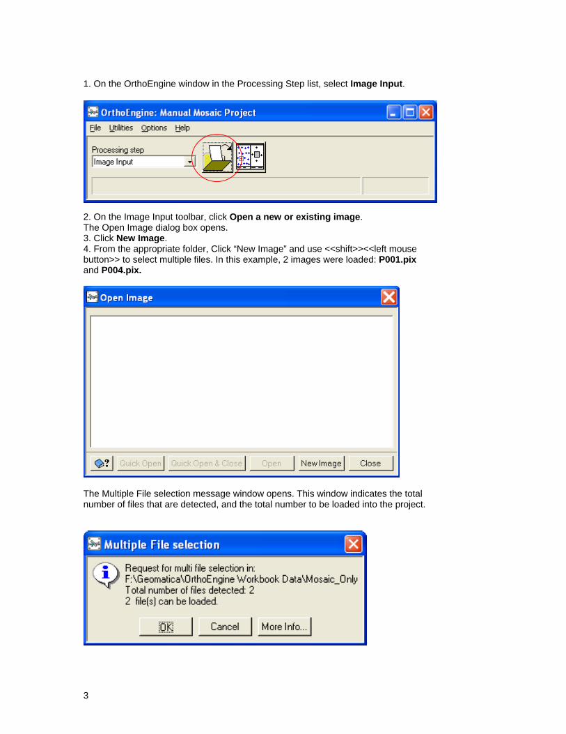
Setting the Projection Parameters No geometric correction is performed for Mosaic Only projects. Therefore, the output projection and pixel spacing must be the same as the input files. For a Mosaic Only project, the output projection and resolution can be extracted from the first image that you add to your project. To set the projection automatically: 1. In the Set Projection dialog box, click Cancel. The Set Projection dialog box closes and a Warning message window opens.
2. Click OK. The output projection and resolution for the project will be automatically set to the projection and resolution of the first image added to the project. You can also set the projection manually using the “Set Projection” panel; the projection and resolution must match the input image files.
Adding Images to the Project Before you start working with the imagery, you will need to import the data into the project. For a ‘mosaic only’ math modeling project, the input images can be in any GDB supported format. Note that compressed formats (JPEG, SID, ECW) should be avoided as they must be uncompressed “on the fly” before they can be used in OrthoEngine. This will slow down the processing speed in OrthoEngine. To add the images to the project:
2
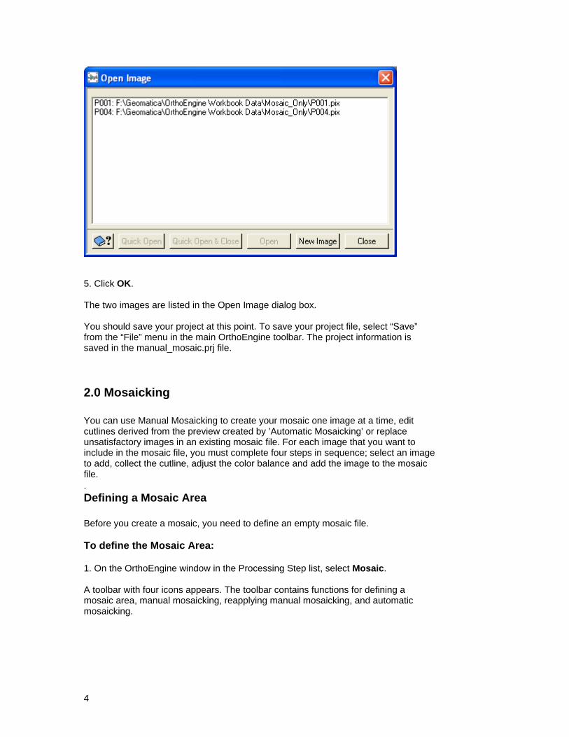
1. On the OrthoEngine window in the Processing Step list, select Image Input.
2. On the Image Input toolbar, click Open a new or existing image. The Open Image dialog box opens. 3. Click New Image. 4. From the appropriate folder, Click “New Image” and use <<shift>><<left mouse button>> to select multiple files. In this example, 2 images were loaded: P001.pix and P004.pix.
The Multiple File selection message window opens. This window indicates the total number of files that are detected, and the total number to be loaded into the project.
3
5. Click OK. The two images are listed in the Open Image dialog box. You should save your project at this point. To save your project file, select “Save” from the “File” menu in the main OrthoEngine toolbar. The project information is saved in the manual_mosaic.prj file.
2.0 Mosaicking You can use Manual Mosaicking to create your mosaic one image at a time, edit cutlines derived from the preview created by ’Automatic Mosaicking’ or replace unsatisfactory images in an existing mosaic file. For each image that you want to include in the mosaic file, you must complete four steps in sequence; select an image to add, collect the cutline, adjust the color balance and add the image to the mosaic file. . Defining a Mosaic Area Before you create a mosaic, you need to define an empty mosaic file. To define the Mosaic Area: 1. On the OrthoEngine window in the Processing Step list, select Mosaic. A toolbar with four icons appears. The toolbar contains functions for defining a mosaic area, manual mosaicking, reapplying manual mosaicking, and automatic mosaicking.
4
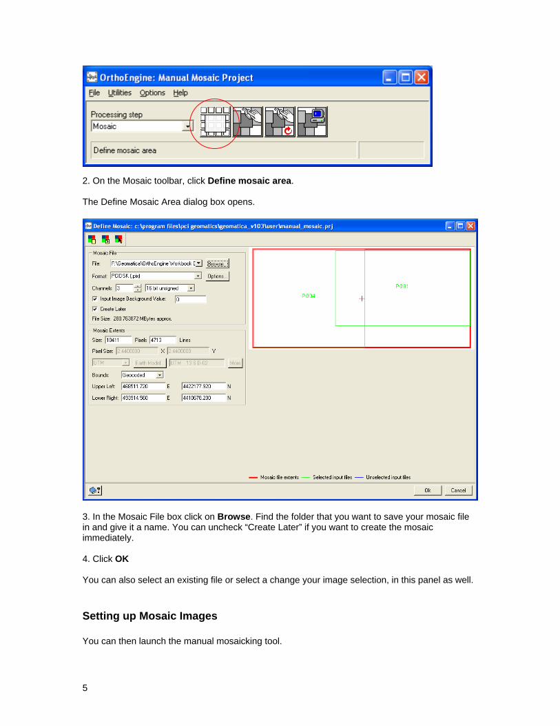
2. On the Mosaic toolbar, click Define mosaic area. The Define Mosaic Area dialog box opens.
3. In the Mosaic File box click on Browse. Find the folder that you want to save your mosaic file in and give it a name. You can uncheck “Create Later” if you want to create the mosaic immediately. 4. Click OK You can also select an existing file or select a change your image selection, in this panel as well.
Setting up Mosaic Images You can then launch the manual mosaicking tool.
5
1. On the Mosaic toolbar, click Manual mosaicking. The Manual Mosaic Tool window opens
You can access the major tools from: a) The “Tools” menu b) The icons in the toolbar or c) Right mouse click on “Cutline”, “Label” or “Maps” under each image in the file tree.
6
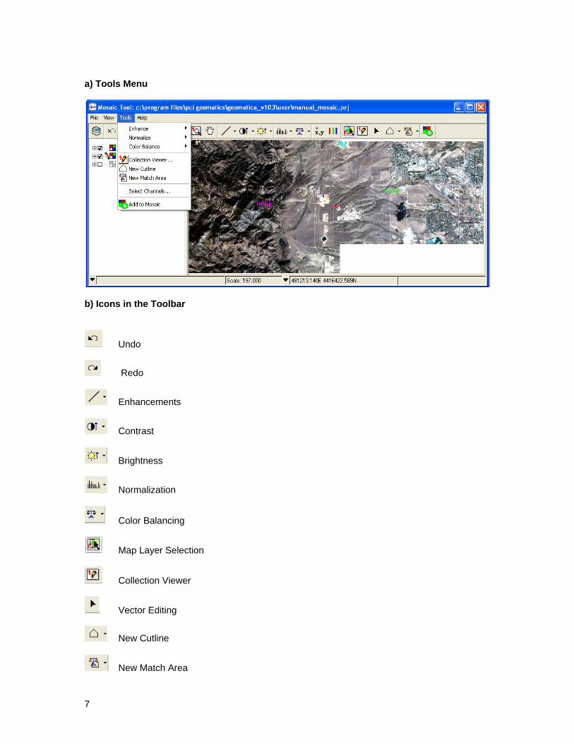
a) Tools Menu
b) Icons in the Toolbar
Undo
Redo
Enhancements
Contrast
Brightness
Normalization
Color Balancing
Map Layer Selection
Collection Viewer
Vector Editing
New Cutline
New Match Area
7
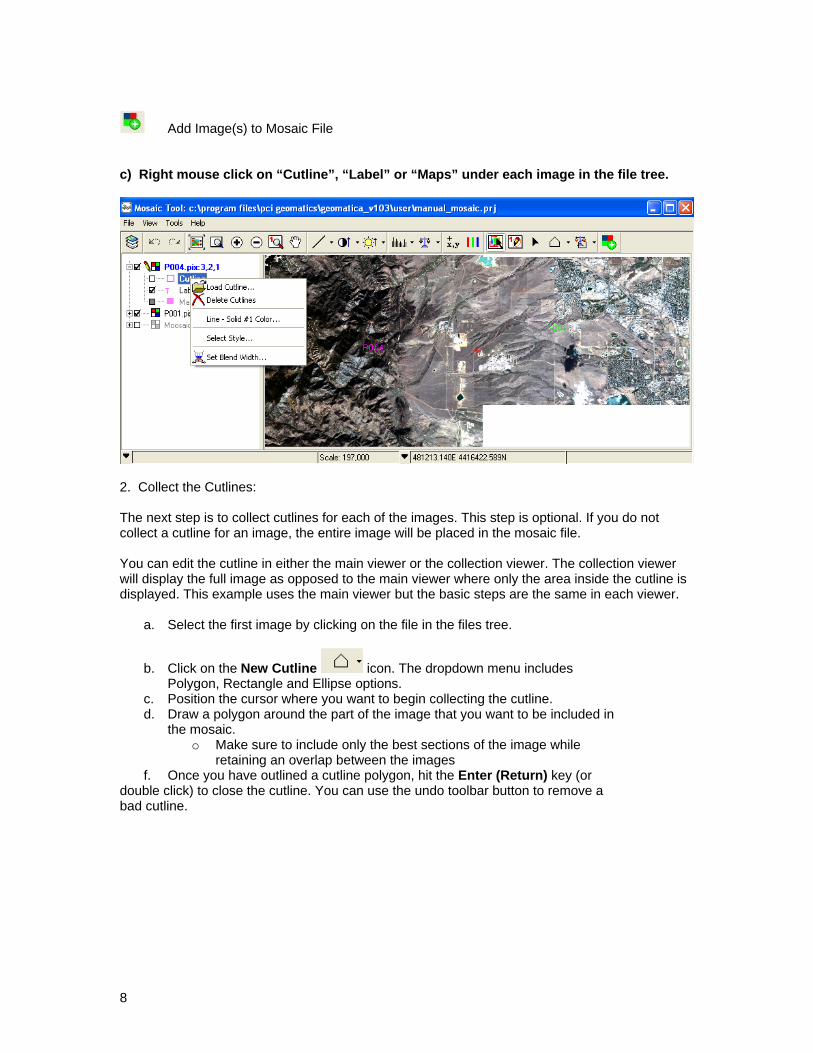
Add Image(s) to Mosaic File c) Right mouse click on “Cutline”, “Label” or “Maps” under each image in the file tree.
2. Collect the Cutlines: The next step is to collect cutlines for each of the images. This step is optional. If you do not collect a cutline for an image, the entire image will be placed in the mosaic file. You can edit the cutline in either the main viewer or the collection viewer. The collection viewer will display the full image as opposed to the main viewer where only the area inside the cutline is displayed. This example uses the main viewer but the basic steps are the same in each viewer.
a. Select the first image by clicking on the file in the files tree.
b. Click on the New Cutline icon. The dropdown menu includes Polygon, Rectangle and Ellipse options.
c. Position the cursor where you want to begin collecting the cutline. d. Draw a polygon around the part of the image that you want to be included in
the mosaic. o Make sure to include only the best sections of the image while
retaining an overlap between the images f. Once you have outlined a cutline polygon, hit the Enter (Return) key (or
double click) to close the cutline. You can use the undo toolbar button to remove a bad cutline.
8
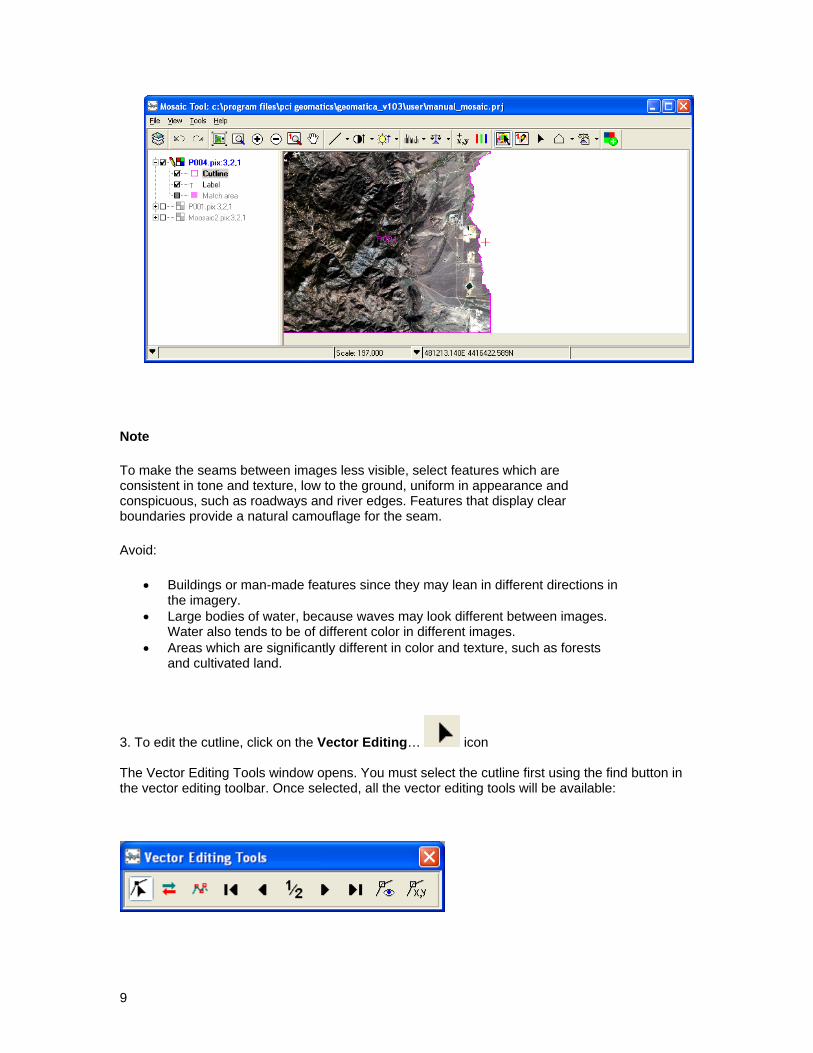
Note
To make the seams between images less visible, select features which are consistent in tone and texture, low to the ground, uniform in appearance and conspicuous, such as roadways and river edges. Features that display clear boundaries provide a natural camouflage for the seam.
Avoid:
Buildings or man-made features since they may lean in different directions in the imagery.
Large bodies of water, because waves may look different between images. Water also tends to be of different color in different images.
Areas which are significantly different in color and texture, such as forests and cultivated land.
3. To edit the cutline, click on the Vector Editing… icon The Vector Editing Tools window opens. You must select the cutline first using the find button in the vector editing toolbar. Once selected, all the vector editing tools will be available:
9
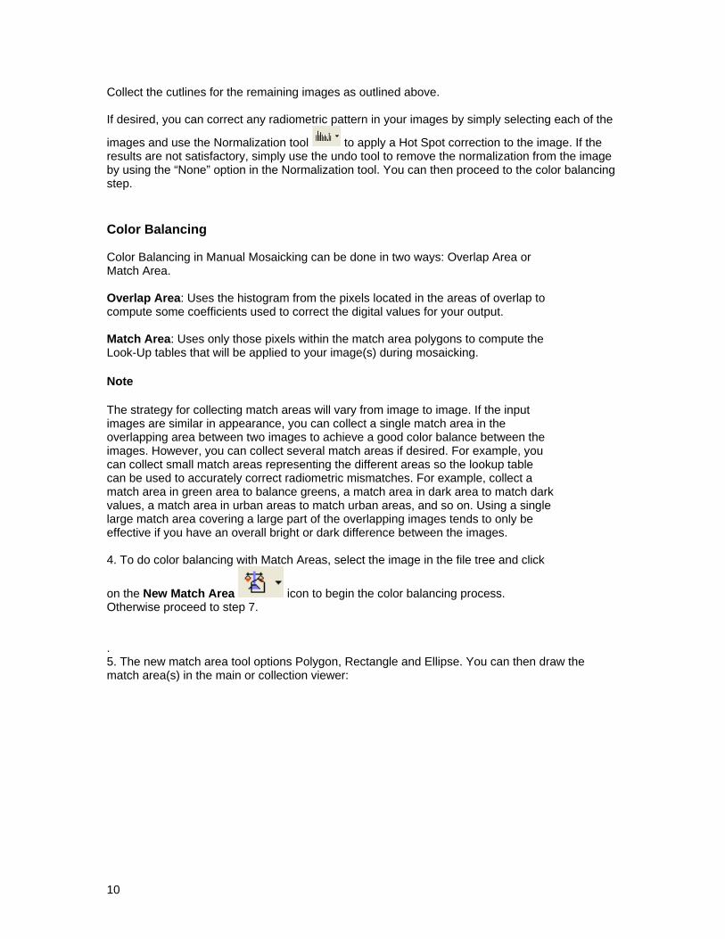
Collect the cutlines for the remaining images as outlined above. If desired, you can correct any radiometric pattern in your images by simply selecting each of the
images and use the Normalization tool to apply a Hot Spot correction to the image. If the results are not satisfactory, simply use the undo tool to remove the normalization from the image by using the “None” option in the Normalization tool. You can then proceed to the color balancing
ep.
olor Balancing
ng in Manual Mosaicking can be done in two ways: Overlap Area or atch Area.
rlap to ompute some coefficients used to correct the digital values for your output.
ompute the ook-Up tables that will be applied to your image(s) during mosaicking.
ote
put
le be
ffective if you have an overall bright or dark difference between the images.
4. To do color balancing s, select the image in the file tree and click
icon to begin the color balancing process. therwise proceed to step 7.
ctangle and Ellipse. You can then draw the atch area(s) in the main or collection viewer:
st C Color BalanciM Overlap Area: Uses the histogram from the pixels located in the areas of ovec Match Area: Uses only those pixels within the match area polygons to cL N The strategy for collecting match areas will vary from image to image. If the inimages are similar in appearance, you can collect a single match area in the overlapping area between two images to achieve a good color balance between the images. However, you can collect several match areas if desired. For example, youcan collect small match areas representing the different areas so the lookup table can be used to accurately correct radiometric mismatches. For example, collect a match area in green area to balance greens, a match area in dark area to match dark values, a match area in urban areas to match urban areas, and so on. Using a singlarge match area covering a large part of the overlapping images tends to onlye
on the New Match Area
with Match Area
O . 5. The new match area tool options Polygon, Rem
10
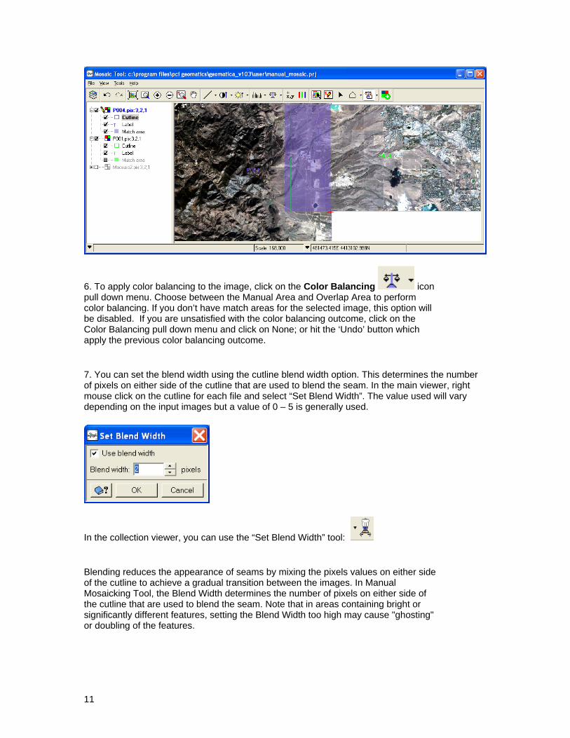
6. To apply color balancing to the image, click on the Color Balancing icon pull down menu. Choose between the Manual Area and Overlap Area to perform color balancing. If you don’t have match areas for the selected image, this option will be disabled. If you are unsatisfied with the color balancing outcome, click on the Color Balancing pull down menu and click on None; or hit the ‘Undo’ button which apply the previous color balancing outcome.
7. You can set the blend width using the cutline blend width option. This determines the number of pixels on either side of the cutline that are used to blend the seam. In the main viewer, right mouse click on the cutline for each file and select “Set Blend Width”. The value used will vary depending on the input images but a value of 0 – 5 is generally used.
In the collection viewer, you can use the “Set Blend Width” tool:
Blending reduces the appearance of seams by mixing the pixels values on either side of the cutline to achieve a gradual transition between the images. In Manual Mosaicking Tool, the Blend Width determines the number of pixels on either side of the cutline that are used to blend the seam. Note that in areas containing bright or significantly different features, setting the Blend Width too high may cause "ghosting" or doubling of the features.
11
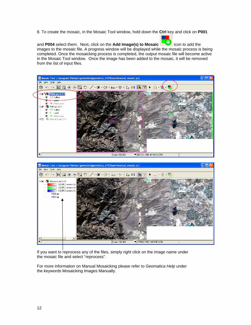
8. To create the mosaic, in the Mosaic Tool window, hold down the Ctrl key and click on P001
and P004 select them. Next, click on the Add Image(s) to Mosaic icon to add the images to the mosaic file. A progress window will be displayed while the mosaic process is being completed. Once the mosaicking process is completed, the output mosaic file will become active in the Mosaic Tool window. Once the image has been added to the mosaic, it will be removed from the list of input files.
12
If you want to reprocess any of the files, simply right click on the image name under the mosaic file and select “reprocess”. For more information on Manual Mosaicking please refer to Geomatica Help under the keywords Mosaicking Images Manually.