99
— MANUAL Motor control and protection unit M10x User Guide

—MANUAL
Motor control and protection unitM10x User Guide

—ABB low voltage MCC with M10x is the intelligent motor control center solution integrating protection, control, monitoring and communication through single M10x, a signature motor management device of ABB low voltage switchgear business.
Main benefits of ABB MCC with M10x• Unmatched safety for protection for personnel and plant• Simplicity and high functionality• Integrated communications• Reliable solution proven by years of market experience• Flexibility in a standardized solution• Less spare starter module types• Rapid fault detection and rectification• Easy integrate and access to digital service• Fully integrated into ABB AbilityTM CMES condition monitor- ing solution
07. Configurable Inputs and Outputs
09. Operator panel MDx
08. Monitoring and reporting
—Contents
01. General 04
02. Product overview 08
03. Installation and wiring 10
04. Motor starters control 22
05. Protection functions 40
06. Control access 61
64
70
72
10.Communication interface 86
11.Parameterization 90
12. Fault messages and troubleshoot 91
13. Appendix A: technical data 95

4 M OTO R CO NTRO L A N D PROTEC TI O N U N IT M10X USER G U I D E
—01. General
Target groupThis manual provides information on the internal parameters of M10x for the purpose of understanding, engineering, testing, system integration or commissioning of the product.
Each chapter consists of brief explanations of the functions, the relevant parameters and the parameter descriptions, along with ranges. Default values of all parameters are listed in appendix: Factory settings for M10x.
Examples and further explanations are provided for user reference in parameterization.
The electrical warning icon indicates the presence of a hazard that could result in electrical shock.
The warning icon indicates the presence of a hazard that could result in personal injury.
The caution icon indicates important information or warnings related to the concept discussed in the text. It might indicate the presence of hazard that could result on corruption of software or damage to equipment/property.
The information icon alerts the reader to pertinent facts and conditions.
The tip icon indicates advice on, for example, how to design your project or how to use a certain function
Use of warning, caution, information and tipiconThis publication includes Warning, Caution, and Information icons where appropriate to point out safety related or other important information. It also includes Tip icons to point out useful hints to the reader. The corresponding symbols should be interpreted as listed on the table below.
Although Warning notices are related to personal
injury, and Caution notices are associated with
equipment or property damage, it should be un-
derstood that the operation of damaged equip-ment could, under certain operational condi-tions, result in impaired process performance
leading to personal injury or death. It is, there-fore, imperative that you comply fully with all Warning and Caution notices.

501 .G EN ER A L
TerminologyList of terms, acronyms, abbreviations and definitions used in the document:
Abbreviation Term Description
Alarm Alarm is defined as status transition from any state to abnormal state.Status transition to abnormal state can be data crossing over the
predefined alarm limit.
DCS Distributed control system High level distributed control system
Local hardwiring A control access term describing that the M10x accepts its
commands from the hardwired inputs when the local control
authority is enabled.
PCS Process control system High level process control system
MODBUS Fieldbus communication protocol
MODBUS RTU Fieldbus communication protocol
PROFIBUS-DP Fieldbus communication protocol with cyclic data transfer (V0).
PROFIBUS-DP/V1 Fieldbus communication protocol, extension of PROFIBUS-DP allowing acyclic data transfer and multi master (V1)
PTC Positive temperature coefficient PTC thermistors are semiconductor elements with a very high positive temperature coefficient.
RCU Remote control unit Local control unit with pushbutton and indicator to operate a device (eg, motor) from field level.
Remote fieldbus A control access term describing that the M10x accepts its commands from the fieldbus inputs when the remote control authority is enabled.
RS485 Communication interface standard from EIA (Electronics Industries Association, USA), operating on voltages between 0V and +5V. RS-485 is
more noise resistant than RS- 232C, handles data transmission over longer distances, and can drive more receivers.
STP Shielded twisted pair A type of cable commonly used for signal transmission.
TOL Thermal overloadprotection
Protection against overheated caused by overload
Trip A consequence of an alarm activated or an external trip command from another device to stop the motor or trip the circuit breaker.
MCC Motor control center Common term for a switchgear used for motor control and protection.
SOE Sequence of events A record of events with time stamp.

6 M OTO R CO NTRO L A N D PROTEC TI O N U N IT M10X USER G U I D E
Related documentation1TNC 911112 M10x User Guide1TNC 911507 M10x-P PROFIBUS Protocol Implementation 1TNC 911505 M10x-M Modbus Protocol Implementation 1TNC 911104 MCUSetup User Guide1TNC928239 M10x -TCP User Guide
Related System VersionThe content of this document is related to M10x products (1TNA920xx) with the following hardware and
firmware version release:
HW FW
M10x-M 24VDC 2.0 3.5
M10x-M 110VAC 1.0 3.5
M10x-M 240VAC 1.0 3.5
M10x-P 24VDC 3.2 5.4
M10x-P 110VAC 1.0 5.4
M10x-P 240VAC 5.2 5.4
MD21 1.0 2.3
MD31 1.0 1.1
EM01 1.0 1.1
Revision Description of change Date
D0201 Initial Edition 10/2003
D0202 Product revisions 10/2005
D0203 Revise COM terminals; Revise terminology of control authority. Revise earth fault setting.
10/2007
D0204 Template changed as per BU Guideline. 10/2010
D0205 Released for M10x products with new hardware, suitable for both M10x-M and M10x-P
01/2013
D0206 Feature "Ready to start" is added to DO 07/2013
D0207 Add in Phase sequence protection and more DO functions, modify main switch supervision function.
09/2016
D0208 Add in insertion cycle supervision, external VT setting and M10x-TCP with EM01 module
02/2020
Until further notice, this document is also applicable for future firmware versions other than those listed above.
The described functions are designed but may not be fully implemented in all details. Please refer to the release notes regarding possible restrictions.
Document revision history

701 .G EN ER A L
New features available in enhanced products (1TNA920xxx)
In comparison with classic products (1TNA911xx)
General features
1 One single type of integrated CT ranging from 0.24~63A replaces all 6 types of CTs in previous products.
2 Products with options for 110VAC or 240VAC power supply and DI types are available in addition to24VDC option.
3 Additional SOE function in M102 provides event recorder data up to 256 events with time stamp.
4 Products in the same categories are made with the same features and functionalities and are only different in power supply and communication interface from each type. For example, M101'srange of products has identical functionalities regardless of different types of power supply and interfaces, such as M101-M 24VDC, M101-P 240VAC, etc.
Physical dimension
1 Main unit dimension remains the same as previous revision. MDx panel is slightly larger in widthand length (both 3mm extra) while cutout dimension remains the same.
Control features
1 Contactor feeder and contactor feeder/RCU are added into starter types.
2 Two separate start types are available for two-speed starters. NR_2N is for two-speed motor withseparate windings while NR_2N Dahlander is for Dahlander connection motor.
3 Control logic in NR_softstarter and REV_softstarter are modified slightly.
4 Control authority feature in M10x-M has been revised to be identical to M10x-P.
Digital inputs and outputs
1 All DIs in M10x are configurable and also selectable with NO or NC.
2 E-stop, Limit 1, Limit 2, External trip input control definition has been revised.
3 More features are added to DOs.
Protection
1 Long start protection is available to provide stall protection during motor startup.
2 Options are provided to enable or disable TOL protection during motor startup.
3 PTC short circuit protection and PTC open circuit protection are available.
Communication
1 Additional communication speeds are available for MODBUS: 38400 bps and 57600 bps.
2 Additional communication option Modbus TCP is added in.
Measuring and monitoring
1 Additional running data are monitored such as current phase unbalance, thermistor resistor, timeto TOL trip, time to TOL reset, startup time, DI status.
2 Phase-to-phase instead of phase-to-neutral voltage is directly measured.
Maintenance
1 More maintenance features are implemented, including providing number of trips, SOE with timestamp, etc.
Operator panel MDx
1 MDx is provided as IP54.
2 Color and function of LEDs are selectable.
3 Messages on MD21 are selectable.
4 Multiple languages are supported including , English and Chinese.
5 Parameter setting via MD21 is available.
6 Parameter setting port on MDx is mini USB connector in lieu of USB connector.
8 M OTO R CO NTRO L A N D PROTEC TI O N U N IT M10X USER G U I D E
—02. Product overview
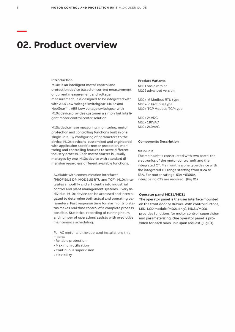
IntroductionM10x is an intelligent motor control andprotection device based on current measurement or current measurement and voltage measurement. It is designed to be integrated with with ABB Low Voltage switchgear MNS® and NeoGearTM . ABB Low voltage switchgear withM10x device provides customer a simply but intelli-gent motor control center solution.
M10x device have measuring, monitoring, motor protection and controlling functions built in one single unit. By configuring of parameters to the device, M10x device is customized and engineered with application specific motor protection, moni-toring and controlling features to serve different industry process. Each motor starter is usually managed by one M10x device with standard di-mension regardless different available functions.
Available with communication interfaces (PROFIBUS DP, MODBUS RTU and TCP), M10x inte-grates smoothly and efficiently into industrial control and plant management systems. Every in-dividual M10x device can be accessed and interro-gated to determine both actual and operating pa-rameters. Fast response time for alarm or trip sta-tus makes real time control of a complete process possible. Statistical recording of running hours and number of operations assists with predictive maintenance scheduling.
For AC motor and the operated installations thismeans:• Reliable protection• Maximum utilization• Continuous supervision• Flexibility
Product VariantsM101 basic versionM102 advanced version
M10x-M Modbus RTU typeM10x-P Profibus typeM10x-TCP Modbus TCP type
M10x 24VDCM10x 110VACM10x 240VAC
Components Description
Main unitThe main unit is constructed with two parts: the electronics of the motor control unit and the integrated CT. Main unit is a one type device with the integrated CT range starting from 0.24 to 63A. For motor ratings 63A ~6300A,interposing CTs are required. (Fig 01)
Operator panel MD21/MD31The operator panel is the user interface mounted on the front door or drawer. With control buttons, LED, LCD module (MD21 only), MD21/MD31 provides functions for motor control, supervision and parameterizing. One operator panel is pro-vided for each main unit upon request.(Fig 01)

90 2 . PR O D U C T OV ER V I E W
Analogue Output Module AO11Analogue output module AO11 is an optional add-on module to main unit, providing one channel 0-20mA or 4-20mA analogue output. Details of AO11 module including how to do the configuration is provided in a separate document, 1TNC 920204 M10x AO Module User Guide.
M10x-TCP Ethernet module EM01Ethernet module EM01 is the dedicated Modbus TCP interface to M10x-TCP. It provides two Ethernet ports. Details of M10x-TCP is de-scribed in 1TNC 928239 M10x-TCP User Guide.
M10x materialThe enclosure of the M10x is made of polycarbonate. Flammability rating of the material is UL 94 V-0 and material is halogen free.
Color of the enclosure is RAL 7012.
—01 M10x and MD21
10 M OTO R CO NTRO L A N D PROTEC TI O N U N IT M10X USER G U I D E
—03. Installation and wiring
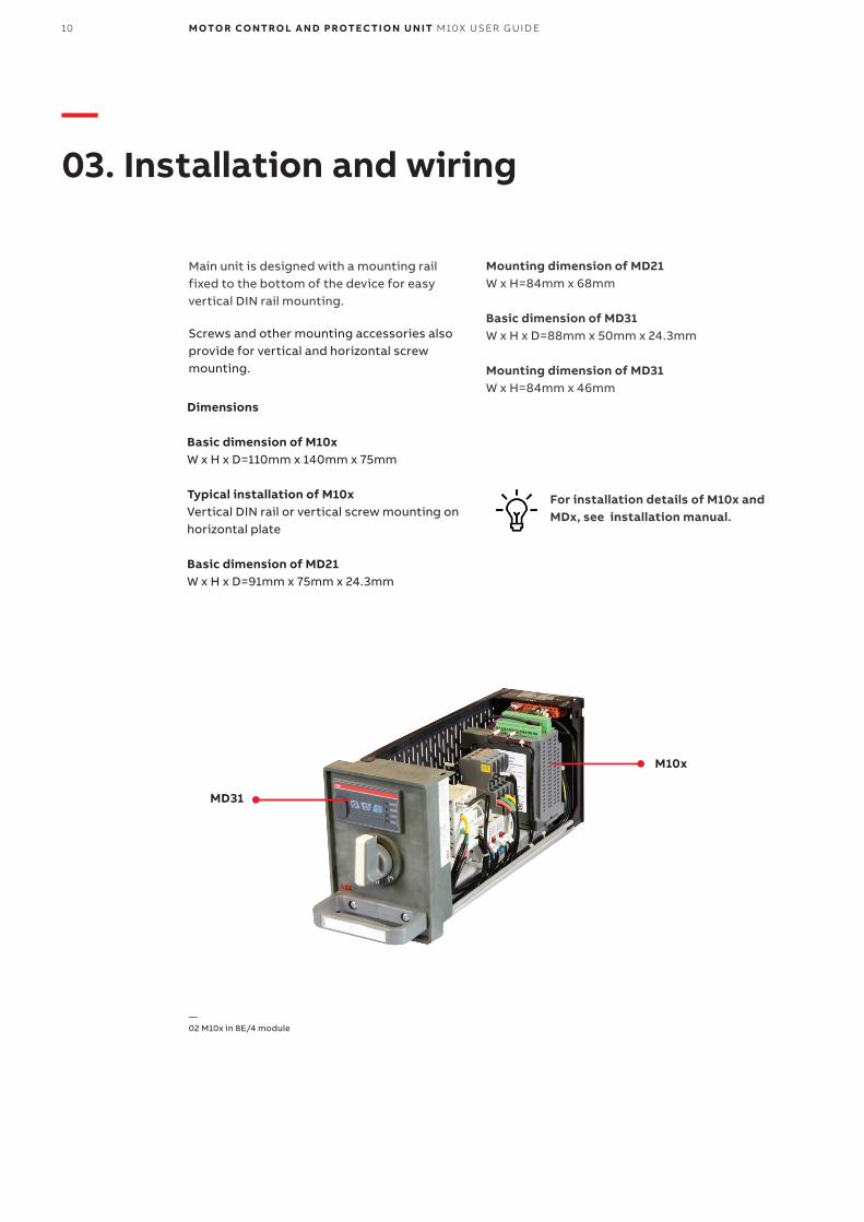
Dimensions
Basic dimension of M10xW x H x D=110mm x 140mm x 75mm
Typical installation of M10xVertical DIN rail or vertical screw mounting on horizontal plate
Basic dimension of MD21W x H x D=91mm x 75mm x 24.3mm
Mounting dimension of MD21 W x H=84mm x 68mm
Basic dimension of MD31W x H x D=88mm x 50mm x 24.3mm
Mounting dimension of MD31 W x H=84mm x 46mm
For installation details of M10x and MDx, see installation manual.
MD31
M10x
—02 M10x in 8E/4 module
Main unit is designed with a mounting rail fixed to the bottom of the device for easy vertical DIN rail mounting.
Screws and other mounting accessories also provide for vertical and horizontal screw mounting.

03 . INSTALLATION AND WIRING 11
Digital inputs for variousfunctions
Digital inputs for variousfunctions
CT inputs (lead-through)
CT inputs (lead-through)
Thermistorinput
Thermistorinput
Interface for MDx
Interface for MDx
Communication ports
Communication ports
RCT inputs
RCT inputs
Relay output
Relay output
Ground safetyand surge
Ground safetyand surge
Voltage input
Voltage input
Power supply
Power supply
1 2 3 4 5 6 7 8 9 10 11 1
1 2 3 4 5 6 7 8 9 10 11 1
2
2
1 2 3 4 5 6 7 8 9 10 11 12 1
1 2 3 4 5 6 7 8 9 10 11 12 1
3
3
1 2 3 4 5 6 7 8 9 10 11 12 13 14 15 1
1 2 3 4 5 6 7 8 9 10 11 12 13 14 15 1
6
6
X2
X2
X1
X1
X3
X3
X4
X4
L
L
T
T
Interfaces Terminal blocks of M10x are located on the top of the main unit for easy access. There are 3 sets of I/O terminal blocks and 1 set of RJ11 connectors as shown.
—03 Top view terminal layout (24VDC)
—04 Top view terminal layout (110VAC or 240VAC)

12 M OTO R CO NTRO L A N D PROTEC TI O N U N IT M10X USER G U I D E
Terminal block Terminal number Designation… plug/contacts Remarks
X1 24VDC type X1:1…X1:14 Digital input Cross section 1.5mm2
X1:15…X1:16 PTC input
X1 110/240VAC type X1:1…X1:10 Digital input Cross section 2.5mm2
X1:11…X1:12 PTC input
X2 X2:1…6 Interface for MDx Cable with RJ11connector provided
X3 X3:1…5 Fieldbus for external communication
Cross section 2.5mm2
X3:6,7 RCT input
X3:8…13 Voltage input
X4 X4:1…9 Relay output Cross section 2.5mm2
X4:10,11 Power supply
X4:12 Ground
L1-T1; L2-T2; L3-T3 Lead-through Current measurement 110mm Window
—Table 1 Terminal blocks and definitions
Terminal designationsRegardless of different types of M10x product, the
definition of the terminal blocks on each type of
M10x remain the same. Depends on the selected
type, the quantities of the available terminal num-
bers may be different.
Integrated L-T Current Measurement Current measurement in M10x is via the inte-
grated current transformer which comes with
one size measuring from 80mA to 63A. Exter-
nal interposing CT shall be used for measuring
from 63~6300A.
To ensure the correct current reading, wiring
of three phases should follow the same direc-
tion, i.e. either L-T or T-L.
In single phase application, current measure-
ment is based on Phase A or L1. The wiring has
to follow L-T direction only.
Current measurement is illustrated in the typi-
cal diagram Fig (13)
Wiring Tip:In the application that motor current is lessthan 500mA, it is essential to increase thewiring turns on CT primary to avoid possi-ble nuisance reading, also known as ghostcurrent. M10x supports up to 5 turns wiringthrough parameter configuration.
The parameters are explained in 'M10x pa-rameters description ' manual.

03 . INSTALLATION AND WIRING 13
FunctionsTerminal no. M10x 24VDCX1:1 DI0
X1:2 DI1
X1:3 DI2
X1:4 DI3
X1:5 DI4
X1:6 DI5
X1:7 DI6
X1:8 DI7
X1:9 DI8
X1:10 DI9
X1:11 DI10
X1:12 DI11
X1:13 DI12
X1:14 DI_COM Digital input common terminal
Digital input common terminal
—Table 2 Digital inputs definition
Terminal block X1 Digital InputsTerminal block X1:1 ~10 is allocated for digital in-
puts (DI) wirings. Depending on voltage type,
there are 13 sets of DIs in M10x 24VDC type and 9
sets in 110/240VAC type. Actual function of DIs is individually configurable.
M10x 110/240VAC
DI0
DI4
DI5
DI6
DI8
DI_COM
DI1
DI2
DI3
DI7
—05 An example of using two sets of power supply
Wiring Tip:As M10x measures the voltage drop through DIs, any unnecessary voltage changes or dis-turbance on DI circuit should be avoided. e.g. if DIs are to be wired to a remote field from the starter in a DC application, a sepa-rate supply from the field may be consid-ered. (Fig 05). If DIs are supplied by AC, an in-terposing relay may be used to segregate the interference from the field.
Configurable
Configurable
Configurable
Configurable
Configurable
Configurable
Configurable
Configurable
Configurable
Configurable
Configurable
Configurable
Configurable
Configurable
Configurable
Configurable
Configurable
Configurable
Configurable
Configurable
Configurable
Configurable
Functions

14 M OTO R CO NTRO L A N D PROTEC TI O N U N IT M10X USER G U I D E
Terminal block X1 PTC input (M102 only)PTC function is available in M102 only. To en-sure the proper reading, type A temperature sensor with a characteristic curve according to IEC 60947-8 shall be used along with the device.
Terminal no. Name Description
X1:15 PTCA PTC measurement input A
X1:16 PTCB PTC measurement input B
Terminal no. Name Description
X1:11 PTCA PTC measurement input A
X1:12 PTCB PTC measurement input B
—Table 3 PTC input terminals (24VDC type)
—Table 4 PTC input terminals (110/240AC type)
Wiring Tip: Standard twisted pair should be used for PTC
circuit wiring. When PTC function is not in use,X1:15 and X1:16 should be shorted.
—06 PTC wiring for M102 24VDC type

03 . INSTALLATION AND WIRING 15
Terminal block X3 Communication interfaceDepending on device type, Modbus RTU inter-face, Profibus DP interface are available through X3. Modbus TCP interface is available in a seper-ate EM01 module which connects to X3.
M10x Modbus type has dual RS485 interfaces supporting a complete redundant network setup.
Wiring Tip:Modbus redundancy feature needs to
be enabled if both interfaces are wired to be used. (Fig8 )
Profibus network requires dedicated Profibus ca-ble type. 5VDC (X3:1) is reserved to supply for net-work terminator. (Fig9)
Details of M10x-TCP wiring is in ' M10x-TCP user guide'. When connecting to EM01, either of the RS485 interface may be wired.
Terminal no. Name Description
X3:1 2B Serial RS485 B
X3:2 2A Serial RS485 A
X3:3 SHIELD 485 shield
X3:4 1B Serial RS485 B
X3:5 1A Serial RS485 A
Terminal no. Name Description
X3:1 5V Power supply 5V+ for bus terminator
X3:2 B RS485 B
X3:3 A RS485 A
X3:4 GND Power supply GND for bus terminator
X3:5 SHIELD Shield
—Table 5 MODBUS dual RS485 interfaces
—Table 6 PROFIBUS RS485 interface
Terminal block X2 Interface for MDx M10x is connected with operator panel MD21/MD31 using RJ11 interface.
Wiring Tip: A dedicated cable is used to connect from X2to MD panel. (Fig 07)
—07 X2 connection with MD21 panel

16 M OTO R CO NTRO L A N D PROTEC TI O N U N IT M10X USER G U I D E
Terminal no. Name Description
X3:6 Ioa Residual current transformer input A
X3:7 Iob Residual current transformer input B
—Table 7 Residual current transformer terminals
Terminal block X3 Residual current inputM10x supports earth fault protection by
wiring external residual current trans-former(RCT) to X3 :6 & 7. M10x dedicated RCT type is ABB LNG CT. (Fig 10)
08 M10x-M X3 Modbus Dual ports wiring 09 M10x-P X3 Profibus wiring
Wiring Tip:Standard twisted pair cable should be
used to wire RCT inputs. When earth fault
protection function is not required, X3: 6
&7 should be shorted.
10 RCT circuit wirng
03 . INSTALLATION AND WIRING 17
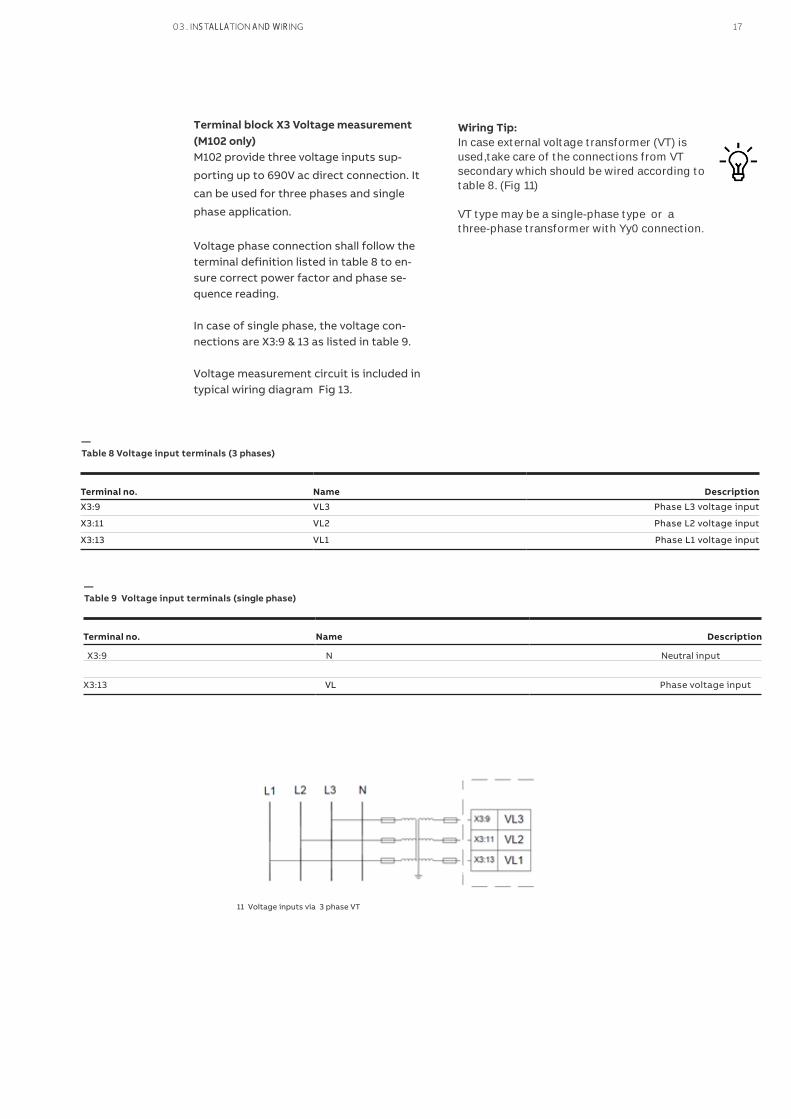
Terminal block X3 Voltage measurement (M102 only)M102 provide three voltage inputs sup-
porting up to 690V ac direct connection. It
can be used for three phases and single
phase application.
Voltage phase connection shall follow the terminal definition listed in table 8 to en-sure correct power factor and phase se-quence reading.
In case of single phase, the voltage con-nections are X3:9 & 13 as listed in table 9.
Voltage measurement circuit is included in typical wiring diagram Fig 13.
Terminal no. Name Description
X3:9 VL3 Phase L3 voltage input
X3:11 VL2 Phase L2 voltage input
X3:13 VL1 Phase L1 voltage input
—Table 8 Voltage input terminals (3 phases)
Wiring Tip:In case external voltage transformer (VT) is used,take care of the connections from VT secondary which should be wired according totable 8. (Fig 11)
VT type may be a single-phase type or athree-phase transformer with Yy0 connection.
Terminal no. Name Description
X3:9 N Neutral input
VLX3:13 Phase voltage input
—Table 9 Voltage input terminals (single phase)
11 Voltage inputs via 3 phase VT

Terminal block X4 Digital output relaysTwo sets of output relays are available from X4:1~5 in M102. Relay 1 (GR1) provides one pair of NC and NO outputs which is configurable as different functions, e.g. trip, alarm indication. Relay 2 (GR2)provides one set of NC output which is also configurable.
Only relay 1 is available in M101 version.
Digital output relays are indicated in typical wiring diagram Fig (13).
Wiring Tip:Take note of the rating operational current and load type of digital out-puts which are listed in technical data section in case a external load is con-nected.
Spark suppression is necessary for connect-ing contactor (except AF type) to ensure areasonable service life of output relays.
GR1 & GR2 contact status may change accord-
ing to the assigned function. For example, ifGR1 is assigned as "trip", NO contact close un-der healthy condition and open under trip.contact status resets during power loss.
Terminal no. Name Description M101 M102
X4:1 GR1_A Programmable relay output 1
X4:2 GR1_B (NO+NC) √
X4:3 GR1_C
√
X4:4 GR2_A Programmable relay output 2 (NO) √
X4:5 GR2_B
—Table 10 Digital output terminals
Terminal block X4 Contactor control relaysThree sets of contactor control relays are avail-
able in M102, i.e. Relay A (CCA), relay B (CCB)
and relay C (CCC). Three relays are pre-config-
ured to respond to different motor starter con-
trol logic. For example, in a direct on line
(DOL) starter control, CCA is dedicated to be
used as open and close the contactor.
CCA and CCB are internally interlocked through
hard-wired.
Only relay CCA and CCB are available in M101.
Wiring Tip:Take note of the rating operational currentand load type of digital outputs which arelisted in technical data section in case a ex-ternal load is connected.
Spark suppression is necessary for con-necting contactor (except AF type) to en-sure a reasonable service life of output re-lays. (Fig 13)
Terminal no. Name Description M101 M102
X4:6 CCLI Contactor control voltage input √ √
X4:7 CCA Contactor control A √ √
X4:8 CCB Contactor control B √ √
X4:9 CCC Contactor control C √
—Table 11 Contactor control terminals
18 M OTO R CO NTRO L A N D PROTE C TI O N U N IT M10X USER G U I D E
Terminal no. Name Description
X4:12 GROUND Ground safety and surge
—Table 12-2 Ground terminal
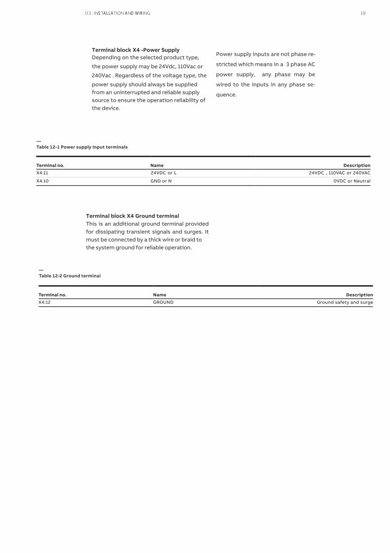
Terminal block X4 Ground terminalThis is an additional ground terminal provided for dissipating transient signals and surges. It must be connected by a thick wire or braid tothe system ground for reliable operation.
Terminal no. Name Description
X4:11 24VDC or L 24VDC , 110VAC or 240VAC
X4:10 GND or N 0VDC or Neutral
—Table 12-1 Power supply input terminals
Terminal block X4 -Power Supply Depending on the selected product type,
the power supply may be 24Vdc, 110Vac or
240Vac . Regardless of the voltage type, the
power supply should always be supplied from an uninterrupted and reliable supply source to ensure the operation reliability of the device.
Power supply inputs are not phase re-
stricted which means in a 3 phase AC
power supply, any phase may be
wired to the inputs in any phase se-
quence.
03 . INSTALLATION AND WIRING 19

Shield and Ground (X4:12) are connected internal of M10x.
Shield and Ground (X4:12) are connected internally in all M10x types.
—12 Typical wiring diagram for M102-M (24VDC type)
Terminal layout example
The terminal layout of M102-M 24VDC product type is shown as an example in Fig 12. The terminal blocks may have dif-ferent definitions and available terminals depending on the selected product type. The details are explained in terminal des-ignations above.
M10x device is certified to work un-der EMC environment according to relevant IEC standards. However a network exposed to high electro-magnetic disturbance may still cause an unstable system and mal-function devices.
In applications that variable speed drives are used in a large scale, harmonic filter de-vices shall be required in system design to reduce impact to the network.
20 M OTO R CO NTRO L A N D PROTEC TI O N U N IT M10X USER G U I D E

—13-1 Typical wiring diagram for M102-M 24VDC DOL PART 1/2
—13-1 Typical wiring diagram for M102-M 24VDC DOL PART 2/2
Wiring Tip:
Using an interface relay between contac-
tor control output relay and contactor coil
will improve the performance and service
life of M10x relay. For a contactor load A75
and above, it is recommended to use an in-
terposing relay.
Typical Wiring Diagram M102-M 24VDC
The terminal layout of M102-M 24VDCproduct type is shown as an example in Fig 12. The terminal blocks may have dif-ferent definitions and available terminals depending on the selected product type. The details are explained in terminal des-ignations above.
03 . INSTALLATION AND WIRING 21

—04. Motor starters control
M10x offers a wide range of pre-configured
motor starter control logic to support various
control applications.
Starter type M101 M102
√ √
√ √
√ √
√ √
√
√
√
√
√
√
√
√ √
√ √
√ √
—Table 13 Starter types supported by M10x
NR_DOL: non reversing direct online
REV_DOL: reversing direct online
NR_DOL/RCU: non reversing direct online with remote control unit
REV_DOL/RCU: reversing direct online with remote control unit
Actuator: actuator with limit switch input
NR_S/D: non reversing star-delta
NR_2N: two-speed driver for non reversing starter with separate winding
NR_2N Dahlander: two-speed driver with Dahlander connection
Autotransformer: starter with autotransformer starting method
NR_softstarter: non reversing starter using softstarter
REV_softstarter: reversing starter using softstarter
Contactor feeder: a general load controlled by a contactor
Contactor feeder/RCU: a general load controlled by a contactor with remote control unit
Feeder: a customized logic for loads controlled by circuit breaker directly
The pre-configured starter control follows the
same control sequence, i.e. from receiving the
command, executing control via output relays
CCA, CCB and CCC, monitoring motor status
through current feedback or contactor status
feedback and confirm the completion or issue
the alarm in case of in-completion of the con-
trol sequence.
The following Fig 14 explains the difference
between NR_DOL and NR_DOL/RCU concern-ing the operation of CCA and CCC relays after receiving the commands. The relation be-tween feedback and motor status is also ex-plained.
Contactor feedback and current feed-back are both used for verification of the motor status. Any unexpected feedback results in alarm or fault.Contactor feedback may be disabled in NR_DOL and contactor feeder starter control. Current feedback is a built in feature ex-cept for contactor feeder and contactor feeder_RCU starters. Current feedback function can not be disabled in other starters. Feedback time is adjustable.
Contactor feedback and
current feedback
22 M OTO R CO NTRO L A N D PROTE C TI O N U N IT M10X USER G U I D E

NR-DOL STARTERNR_DOL starter is a basic starter type for driving motor in one direction. When start command has been received from fieldbus
or local I/O, the contactor control output will be energized and remains in this in condition until stop command has been received or any protection function is activated.
Name Pin Description
CCLI X4:6 Contactor control voltage input
CCA X4:7 Contactor control A
DI6(F_Ca) X1:7 Contactor control A feedback
DI5(Loc/R) X1:6 Local/remote control switch input
—Table 14 NR-DOL starter contactor control interface (for M10x)
—14 Timing diagram of control sequence NR-DOL
* The assigned DI and PIN code may change in actual design
Operating sequence
• Starting Sequence: Motor is stopped and ready to start → START command (Start 1) received → Internal CCA contact closed and remain closed → Feedback received
• Stopping Sequence: Motor is running → STOP command received → Internal CCA contact open → Feedback received
Contactor feedback and current feedback are both used for verification of the mo-tor status. Any unexpected feedback re-sults in alarm or fault.
Contactor feedback can be disabled through parameter. Current feedback r isalways on the background to ensure the completion of an expected operation sequence. The feedback time is adjustable.
0 4 . MOTOR STARTERS CONTROL 23
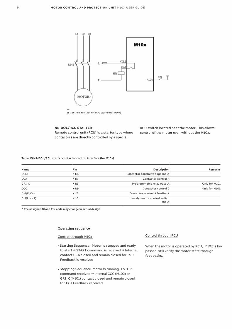
—15 Control circuit for NR-DOL starter (for M10x)
NR-DOL/RCU STARTERRemote control unit (RCU) is a starter type where contactors are directly controlled by a special
RCU switch located near the motor. This allows control of the motor even without the M10x.
Name Pin Description Remarks
CCLI X4:6 Contactor control voltage input
CCA X4:7 Contactor control A
GR1_C X4:3 Programmable relay output Only for M101
CCC X4:9 Contactor control C Only for M102
DI6(F_Ca) X1:7 Contactor control A feedback
DI5(Loc/R) X1:6 Local/remote control switch input
—Table 15 NR-DOL/RCU starter contactor control interface (for M10x)
* The assigned DI and PIN code may change in actual design
Operating sequence
Control through M10x-
• Starting Sequence: Motor is stopped and ready to start → START command is received → Internal contact CCA closed and remain closed for 1s → Feedback is received
• Stopping Sequence: Motor is running → STOP command received → internal CCC (M102) or GR1_C(M101) contact closed and remain closed for 1s → Feedback received
Control through RCU
When the motor is operated by RCU, M10x is by-passed still verify the motor state through feedbacks.
24 M OTO R CO NTRO L A N D PROTEC TI O N U N IT M10X USER G U I D E

—16 Control circuit for NR-DOL/RCU starter (for M101)
—17 Control circuit for NR-DOL/RCU starter (for M102)
Current feedback of a DOL-RCU starter is always on the background to ensure the completion of an expected operation sequence and the confirmation of the motor state during RCU control. The feedback time is adjustable.
Contactor feedback and current feedback are both used for verification of the mo-tor status. Any unexpected feedback re-sults in alarm or fault.
Contactor feedback is a must parameter and can not be disabled as M10x also re-quires contactor feedback to sychronize with external RCU control.
0 4 . MOTOR STARTERS CONTROL 25

—18 Control circuit for REV-DOL starter (for M10x)
REV-DOL STARTERREV-DOL uses contactor control output A to control the contactor that drives the motor in direction CW. Correspondingly, contactor control output B is used for direction CCW. When the
starting motor to either direction contactor will be energized and is stopped (not energized) by command from fieldbus or local I/O, or active protection function.
Name Pin Description
CCLI X4:6 Contactor control voltage input
CCA X4:7 Contactor control A
CCB X4:8 Contactor control B
DI6(F_Ca) X1:7 Contactor control A feedback
DI7(F_Cb) X1:8 Contactor control B feedback
DI5(Loc/R) X1:6 Local/remote control switch input
—Table 16 REV-DOL starter contactor control interface (for M10x)
* The assigned DI and PIN code may change in actual design
Operating sequence under REV-DOL
• Running forward Sequence: Motor is stopped and ready to run forward → Forward command (Start 1) received → Internal CCA contact closed and remain closed → Feedback received
• Reversing Sequence: Motor is stopped and ready to reverse → Reverse command (Start 2) received → Internal CCB contact close and remain closed → Feedback received
• Stopping Sequence: Motor is running → STOP command received → Internal CCA & CCB contact open → Feedback received
Contactor feedback is used for acknowledge the running direction hence can not be disabled through parameter in a REV-DOL starter. Current feedback is always on the background to ensure the completion of an expected operation sequence. The feedback time is adjustable.
Take note of the CT location for the application. CT location should be on the line side of both K1 and K2 to ensure correct current phase sequence reading.
26 M OTO R CO NTRO L A N D PROTEC TI O N U N IT M10X USER G U I D E

Name Pin Description Remarks
CCLI X4:6 Contactor control voltage input
CCA X4:7 Contactor control A
CCB X4:8 Contactor control B
GR1_C X4:3 Programmable relay output1 Only for M101
CCC X4:9 Contactor control C Only for M102
DI6(F_Ca) X1:7 Contactor control A feedback
DI7(F_Cb) X1:8 Contactor control B feedback
DI5(Loc/R) X1:6 Local/remote control switch input
—Table 17 REV-DOL starter contactor control interface (for M10x)
REV-DOL/RCU starterThe functionality of this starter type is the same as the NR-DOL/RCU starter with support for reversing use of motor.
* The assigned DI and PIN code may change in actual design
Operating sequence under REV-DOL/RCU
Control through M10x-
• Running forward Sequence: Motor is stopped and ready to run forward → Forward command (Start 1) received → Internal CCA contact closed and remain closed for 1s → Feedback received
• Reversing Sequence: Motor is stopped and ready to reverse → Reverse command (Start 2) received → Internal CCB contact close and remain closed for 1s → Feedback received
• Stopping Sequence: Motor is running → STOP command received → internal CCC (M102) or GR1_C(M101) contact closed and remain closed for 1s → Feedback received
Control through RCU-
When the motor is operated by RCU, M10x is by-passed still verify the motor state through feedbacks.
Contactor feedback is a must parameter and can not be disabled as M10x also requires contactor feedback to sychronize with external RCU control.
Current feedback of a RCU starter is always onthe background to ensure the completion of an expected operation sequence and the confirmation of the motor state during RCU control. The feedback time is adjustable.
Take note of the CT location for the application. CT location should be on the line side of both K1 and K2 to ensure correct current phase sequence reading.
0 4 . MOTOR STARTERS CONTROL 27
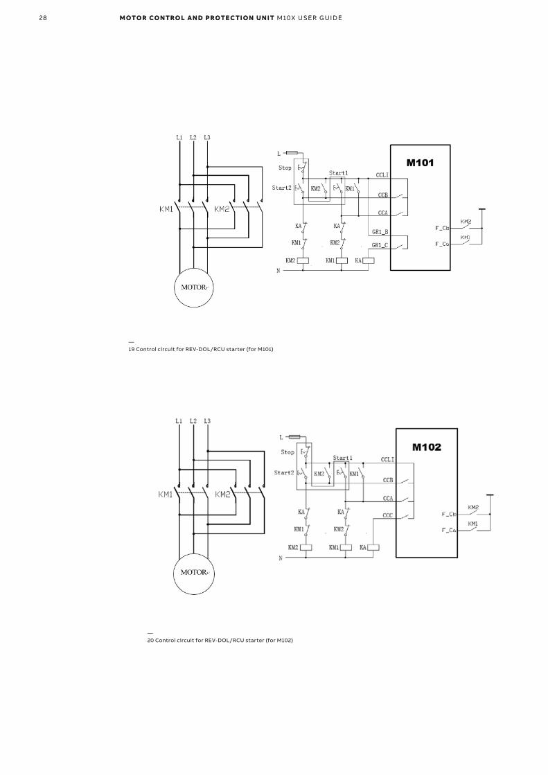
—20 Control circuit for REV-DOL/RCU starter (for M102)
—19 Control circuit for REV-DOL/RCU starter (for M101)
28 M OTO R CO NTRO L A N D PROTEC TI O N U N IT M10X USER G U I D E28 M OTO R CO NTRO L A N D PROTEC TI O N U N IT M10X USER G U I D E
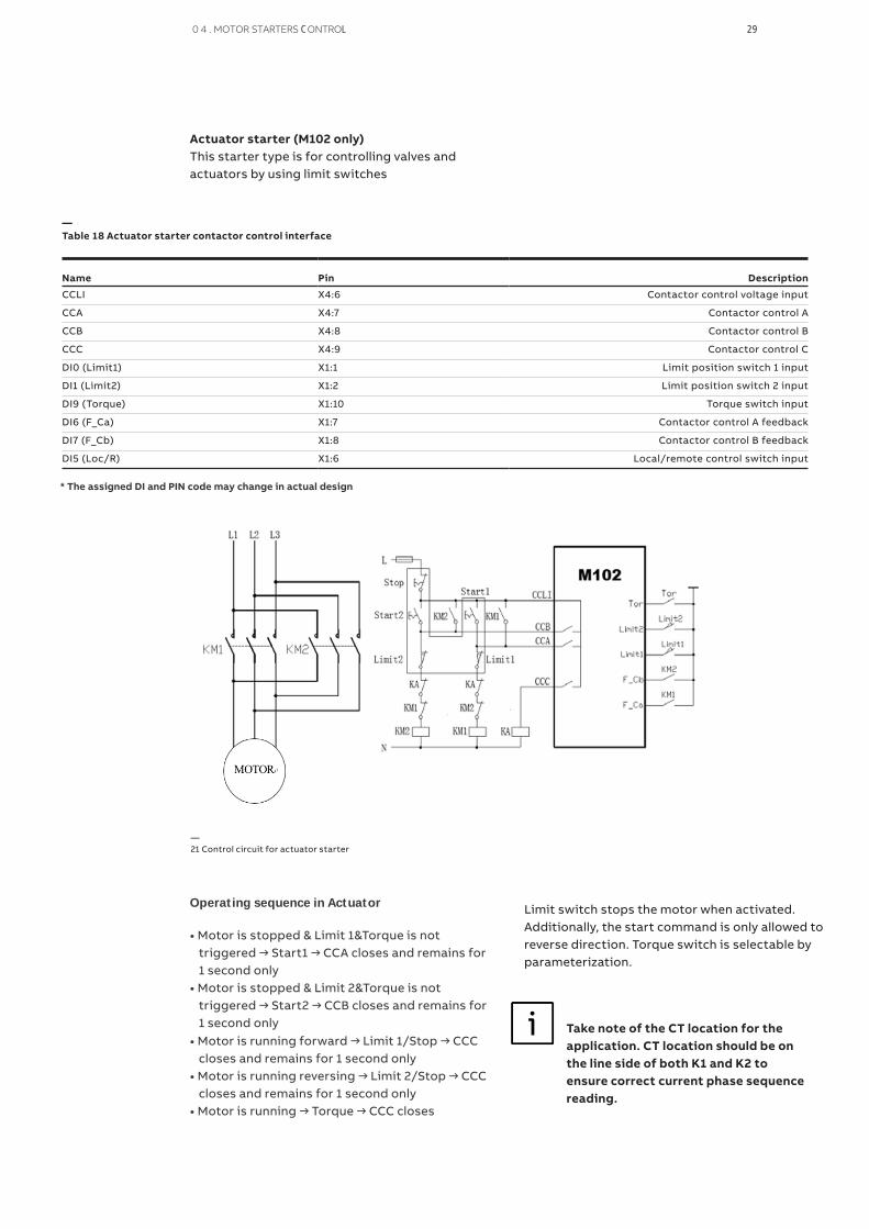
Actuator starter (M102 only)This starter type is for controlling valves and actuators by using limit switches
Name Pin Description
CCLI X4:6 Contactor control voltage input
CCA X4:7 Contactor control A
CCB X4:8 Contactor control B
CCC X4:9 Contactor control C
DI0 (Limit1) X1:1 Limit position switch 1 input
DI1 (Limit2) X1:2 Limit position switch 2 input
DI9 (Torque) X1:10 Torque switch input
DI6 (F_Ca) X1:7 Contactor control A feedback
DI7 (F_Cb) X1:8 Contactor control B feedback
DI5 (Loc/R) X1:6 Local/remote control switch input
—Table 18 Actuator starter contactor control interface
—21 Control circuit for actuator starter
Limit switch stops the motor when activated. Additionally, the start command is only allowed to reverse direction. Torque switch is selectable by parameterization.
Operating sequence in Actuator
• Motor is stopped & Limit 1&Torque is not triggered → Start1 → CCA closes and remains for 1 second only• Motor is stopped & Limit 2&Torque is not triggered → Start2 → CCB closes and remains for 1 second only• Motor is running forward → Limit 1/Stop → CCC closes and remains for 1 second only• Motor is running reversing → Limit 2/Stop → CCC closes and remains for 1 second only• Motor is running → Torque → CCC closes
Take note of the CT location for the application. CT location should be on the line side of both K1 and K2 to ensure correct current phase sequence reading.
* The assigned DI and PIN code may change in actual design
0 4 . MOTOR STARTERS CONTROL 29

Name Pin Description
CCLI X4:6 Contactor control voltage input
CCA X4:7 Contactor control A
CCB X4:8 Contactor control B
CCC X4:9 Contactor control C
DI5 (Loc/R) X1:6 Local/remote control switch input
DI6 (F_Ca) X1:7 Contactor control A feedback
DI7 (F_Cb) X1:8 Contactor control B feedback
DI8 (F_Cc) X1:9 Contactor control C feedback
DI7 (F_Cb) X1:8 Contactor control B feedback
DI5 (Loc/R) X1:6 Local/remote control switch input
—Table 19 NR_S/D starter contactor control interface
—22 Control circuit for NR-S/D starter
NR-S/D starter (M102 only)Motor start current is reduced in star connection to 1/3 of the current in delta connection, with lower torque during the same time.
Star-to-delta starting sequence is based on
the presented control logic (Fig22).The changeover condition is time.
Operating sequence in NR-S/D
Motor is stopped → Start1 → CCB&CCC close → changeover time → CCB opens & CCA closes
Motor is running → Stop → CCA&CCB&CCC open
* The assigned DI and PIN code may change in actual design
Take note of changeover time and mo-
tor startup time setting
Changeover time < Motor startup time
30 M OTO R CO NTRO L A N D PROTE C TI O N U N IT M10X USER G U I D E
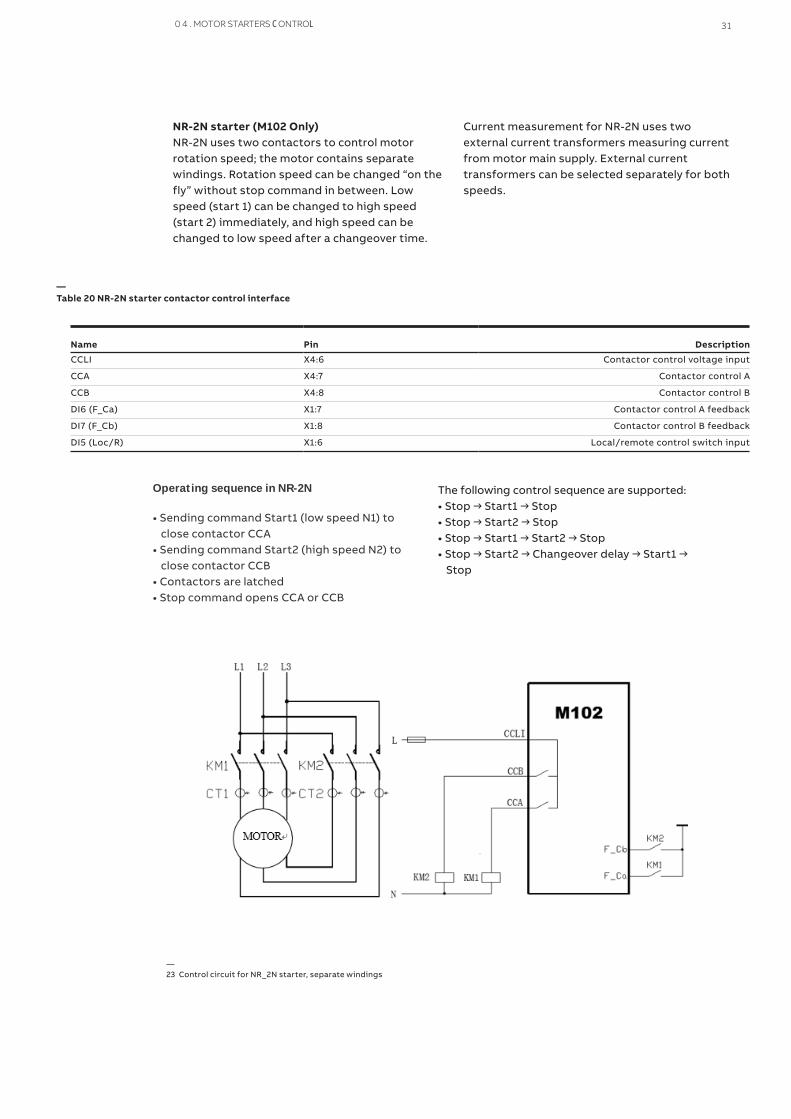
NR-2N starter (M102 Only)NR-2N uses two contactors to control motor rotation speed; the motor contains separate windings. Rotation speed can be changed “on the fly” without stop command in between. Low speed (start 1) can be changed to high speed (start 2) immediately, and high speed can be changed to low speed after a changeover time.
Current measurement for NR-2N uses two external current transformers measuring current from motor main supply. External current transformers can be selected separately for both speeds.
—Table 20 NR-2N starter contactor control interface
—23 Control circuit for NR_2N starter, separate windings
Operating sequence in NR-2N
• Sending command Start1 (low speed N1) to close contactor CCA• Sending command Start2 (high speed N2) to close contactor CCB• Contactors are latched• Stop command opens CCA or CCB
The following control sequence are supported:• Stop → Start1 → Stop• Stop → Start2 → Stop• Stop → Start1 → Start2 → Stop• Stop → Start2 → Changeover delay → Start1 → Stop
Name Pin Description
CCLI X4:6 Contactor control voltage input
CCA X4:7 Contactor control A
CCB X4:8 Contactor control B
DI6 (F_Ca) X1:7 Contactor control A feedback
DI7 (F_Cb) X1:8 Contactor control B feedback
DI5 (Loc/R) X1:6 Local/remote control switch input
0 4 . MOTOR STARTERS CONTROL 31

Name Pin Description
CCLI X4:6 Contactor control voltage input
CCA X4:7 Contactor control A
CCB X4:8 Contactor control B
CCC X4:9 Contactor control C
DI5 (Loc/R) X1:6 Local/remote control switch input
DI6 (F_Ca) X1:7 Contactor control A feedback
DI7 (F_Cb) X1:8 Contactor control B feedback
DI8 (F_Cc) X1:9 Contactor control C feedback
—Table 21 NR-2N Dahlander starter contactor control interface
—24 Control circuit for NR_2N Dahlander starter
NR-2N Dahlander STARTER (M102 Only)NR-2N Dahlander uses three contactors to control motor rotation speed where motor is equipped with a three-phase winding. Rotation speed can be changed “on the fly” without stop command in between. Low speed (start 1) can be changed to high speed (start 2) immediately, and high speed can be changed to low speed after a changeover time.
Current measurement for NR-2N Dahlander uses two external current transformers measuring current from motor main supply. External current transformers can be selected separately for both speeds.
Operating sequence in NR-2N Dahlander
•Sending command Start1 (low speed N1) to close contactor CCA• Sending command Start2 (high speed N2) to close contactor CCB• Contactors are latched• Stop command opens CCA or CCB
* The assigned DI and PIN code may change in actual design
The following control sequence are supported:• Stop → Start1 → Stop• Stop → Start2 → Stop• Stop → Start1 → Start2 → Stop• Stop → Start2 → Changeover delay → Start1 → Stop
32 M OTO R CO NTRO L A N D PROTE C TI O N U N IT M10X USER G U I D E

Autotransformer starter (M102 only)This starter type is used to control the autotransformer unit in order to minimize voltage drop during motor startup. Autotransformer starter with three contactors supports motor
starting with reduced voltage, thus providing reduced motor startup current. The starting torque will be reduced accordingly,
Name Pin Description
CCLI X4:6 Contactor control voltage input
CCA X4:7 Contactor control A
CCB X4:8 Contactor control B
CCC X4:9 Contactor control C
DI5 (Loc/R) X1:6 Local/remote control switch input
DI6 (F_Ca) X1:7 Contactor control A feedback
DI7 (F_Cb) X1:8 Contactor control B feedback
—Table 22 Autotransformer starter contactor control interface
Operating sequence in Autotransformer
• Motor is stopped → Start1 → CCB&CCC close → changeover time → CCB opens & CCA closes
• Motor is running → Stop → CCA&CCB & CCC open
—25 Control circuit for autotransformer starter
* The assigned DI and PIN code may change in actual design
Take note of changeover time and mo-
tor startup time setting
Changeover time < Motor startup time
0 4 . MOTOR STARTERS CONTROL 33

Name Pin Description
CCLI X4:6 Contactor control voltage input
CCA X4:7 Contactor control A
CCC X4:9 Contactor control C
DI6 (F_Ca) X1:7 Contactor control A feedback
DI5 (Loc/R) X1:6 Local/remote control switch input
—Table 23 NR_softstarter starter contactor control interface.
—26 Control circuit for NR-softstarter
NR-softstarter (M102 only)Softstarter applications are for controlling the motor accessory softstarter device. M102 gives start and stop commands to the softstarter unit. The softstarter is set for adjusting motor voltage with its own parameters. More information about softstarter can be found in the softstarter manual.
This starter type supports all protection functions during normal running situations.For motor start and stop period, some of the protection functions are disabled by these parameters. Current feedback function is suppressed under soft-starter control.
Operating sequence in NR-softstarter
• Motor is stopped → Start1 → CCA closes → CCC closes• Motor is running → Stop → CCC opens → ramp down time → CCA opens
* The assigned DI and PIN code may change in actual design
34 M OTO R CO NTRO L A N D PROTE C TI O N U N IT M10X USER G U I D E
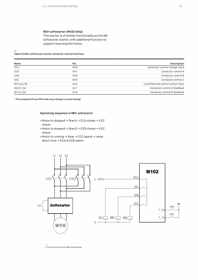
REV-softstarter (M102 Only)This starter is of similar functionality as the NR-softstarter starter, with additional function to support reversing the motor.
Name Pin Description
CCLI X4:6 Contactor control voltage input
CCA X4:7 Contactor control A
CCB X4:8 Contactor control B
CCC X4:9 Contactor control C
DI5 (Loc/R) X1:6 Local/Remote control switch input
DI6 (F_Ca) X1:7 Contactor control A feedback
DI7 (F_Cb) X1:8 Contactor control B feedback
—Table 24 REV-softstarter starter contactor control interface
Operating sequence in REV-softstarter
• Motor is stopped → Start1 → CCA closes → CCC closes• Motor is stopped → Start2 → CCB closes → CCC closes• Motor is running → Stop → CCC opens → ramp down time → CCA & CCB opens
—27 Control circuit for REV-softstarter
* The assigned DI and PIN code may change in actual design
0 4 . MOTOR STARTERS CONTROL 35

Name Pin Description
CCLI X4:6 Contactor control voltage input
CCA X4:7 Contactor control A
DI6(F_Ca) X1:5 Contactor control A feedback
DI5(Loc/R) X1:6 Local/remote control switch input
—Table 25 Contactor feeder contactor control interface
—28 Control circuit for contactor feeder
Contactor feederContactor feeder in M10x is designed for symmetric 3 phase load or single phase load. All measurement, control and protection features which are available to NR-DOL are available to contactor feeder load.
Unlike the NR-DOL logic in which current feedback
is a built in feature, current feedback is no longer
required for motor status verification in contactor
feeder control.
* The assigned DI and PIN code may change in actual design
Operating sequence
• Starting Sequence: Motor is stopped and ready to start → START command (Start 1) received → Internal CCA contact closed and remain closed → Feedback received
• Stopping Sequence: Motor is running → STOP command received → Internal CCA contact open → Feedback received
Contactor feedback is used for verifica-tion of the motor status. Any unex-pected feedback results in alarm or fault.
Contactor feedback can be disabled through parameter. The feedback time is adjustable.
36 M OTO R CO NTRO L A N D PROTE C TI O N U N IT M10X USER G U I D E
Contactor feeder/RCURemote control unit (RCU) is a starter type where contactors are directly controlled by a special RCU switch located near the motor. This allows control of the motor even without the M10x.
Contactor feeder in M10x is designed for symmetric 3 phase load or single phase load. All measurement, control and protection features
which are available to NR-DOL/RCU are available to contactor feeder/RCU load.
Unlike in NR-DOL/RCU control, current feedback is no longer required in contactor feeder/RCU con-trol. Contactor feedback is used for motor status verification and can not be switched off. Feed-back time is adjustable.
—Table 26 Contactor feeder/RCU contactor control interface (for M10x)
Name Pin Description Remarks
Contactor feeder/RCU contactor control
CCLI X4:6 Contactor control voltage input
CCA X4:7 Contactor control A
GR1_C X4:3 Programmable relay output Only for M101
CCC X4:9 Contactor control C Only for M102
DI6(F_Ca) X1:7 Contactor control A feedback
DI5(Loc/R) X1:6 Local/remote control switch input
DI5(Loc/R) X1:6 Local/remote control switch input
* The assigned DI and PIN code may change in actual design
Operating sequence
Control through M10x-
• Starting Sequence: Motor is stopped and ready to start → START command is received → Internal contact CCA closed and remain closed for 1s → Feedback is received
• Stopping Sequence: Motor is running → STOP command received → internal CCC (M102) or GR1_C(M101) contact closed and remain closed for 1s → Feedback received
Control through RCU
When the motor is operated by RCU, M10x is by-passed still verify the motor state through feedbacks.
Contactor feedback is used for verifica-tion of the motor status. Any unexpected feedback results in alarm or fault.
Contactor feedback is a must parameter and can not be disabled as M10x also re-quires contactor feedback to synchro-nize with external RCU control.
0 4 . MOTOR STARTERS CONTROL 37

—30 Control circuit for contactor feeder/RCU (for M101)
—29 Control circuit for contactor feeder/RCU (for M101)
38 M OTO R CO NTRO L A N D PROTE C TI O N U N IT M10X USER G U I D E

FeederFeeder is the control logic customized for the load controlled by circuit breaker directly without using a contactor. The feeder application in M10x pro-vide measurement and control functionality only.
Name Pin Description
CCLI X4:6 Contactor control voltage input
CCA X4:7 Control YC /motor drive in MCCB (2 seconds holding)
CCB X4:8 Control YO/motor drive in MCCB (2 seconds holding)
DI6 (F_Ca) X1:7 Circuit breaker position aux. feedback
DI9 (External trip input) X1:10 Circuit breaker trip aux. feedback
DI5 (Loc/R) X1:6 Local/remote control switch input*
—Table 27 Feeder control interface
* The assigned DI and PIN code may change in actual design
Depending on the type of the load, pro-tection functions which are designed for motors in M10x may not be suitable for feeder load and shall be carefully se-lected or switched off.
• Operating:Start 1 command activates contactor output relay CCA for 2 seconds. Start 2 command activates contactor output relay CCB for 2 seconds.
External trip occurs a trip message and will be re-set when the signal is inactive.
• Monitoring:Circuit breaker close/open status Circuit breaker trip
• Protection:Motor protection functions are not suitable for feeder application. All protections except earth fault protection in M10x are automatically disabled during parameter setting when feeder type is selected.
• Measuring:Current, voltage are measured by M10x. Power, energy and other parameters related to power factor are NOT correct and should not be referred to.
Feeder application is customized as following,
—31 Control circuit for feeder
0 4 . MOTOR STARTERS CONTROL 39
40 M OTO R CO NTRO L A N D PROTE C TI O N U N IT M10X USER G U I D E
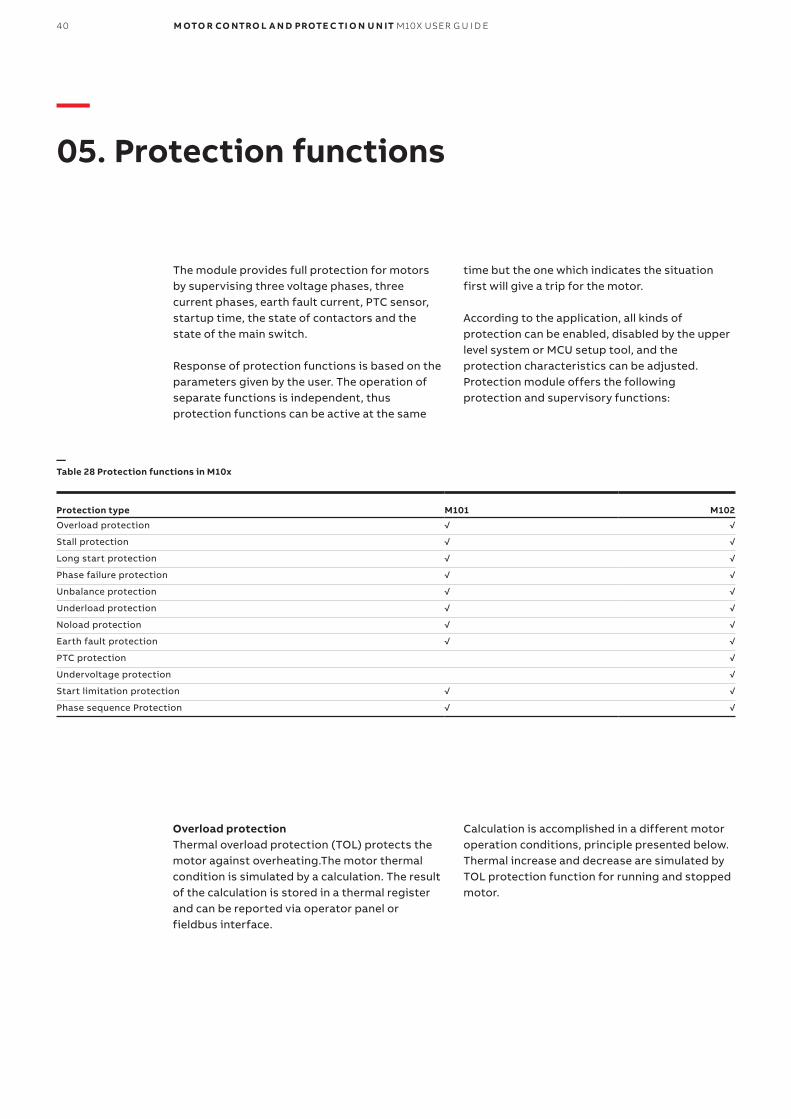
—05. Protection functions
The module provides full protection for motors by supervising three voltage phases, three current phases, earth fault current, PTC sensor, startup time, the state of contactors and the state of the main switch.
Response of protection functions is based on the parameters given by the user. The operation of separate functions is independent, thus protection functions can be active at the same
time but the one which indicates the situation first will give a trip for the motor.
According to the application, all kinds of protection can be enabled, disabled by the upper level system or MCU setup tool, and the protection characteristics can be adjusted. Protection module offers the following protection and supervisory functions:
Protection type M101 M102
Overload protection √ √
Stall protection √ √
Long start protection √ √
Phase failure protection √ √
Unbalance protection √ √
Underload protection √ √
Noload protection √ √
Earth fault protection √ √
PTC protection √
Undervoltage protection √
Start limitation protection √ √
Phase sequence Protection √ √
—Table 28 Protection functions in M10x
Overload protectionThermal overload protection (TOL) protects the motor against overheating.The motor thermal condition is simulated by a calculation. The result of the calculation is stored in a thermal register and can be reported via operator panel or fieldbus interface.
Calculation is accomplished in a different motor operation conditions, principle presented below. Thermal increase and decrease are simulated by TOL protection function for running and stopped motor.
0 5 . PR OTEC TI O N FU N C TI O NS 41
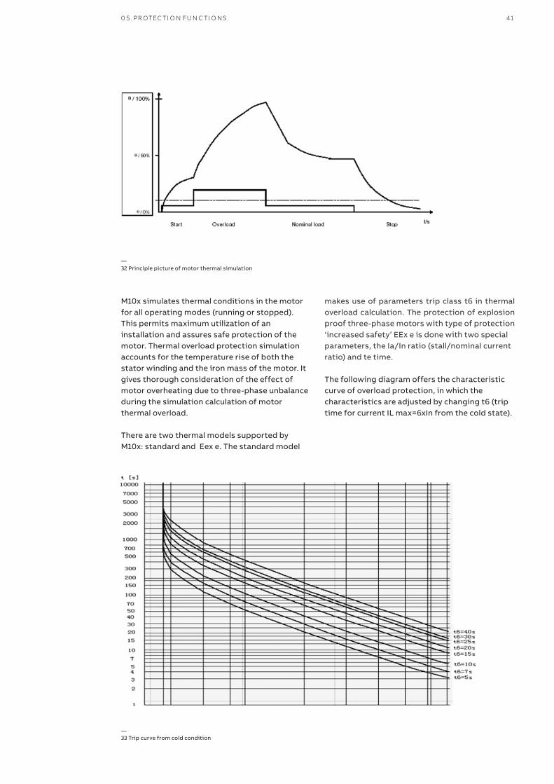
M10x simulates thermal conditions in the motor for all operating modes (running or stopped). This permits maximum utilization of an installation and assures safe protection of the motor. Thermal overload protection simulation accounts for the temperature rise of both the stator winding and the iron mass of the motor. It gives thorough consideration of the effect of motor overheating due to three-phase unbalance during the simulation calculation of motor thermal overload.
There are two thermal models supported by M10x: standard and Eex e. The standard model
—32 Principle picture of motor thermal simulation
—33 Trip curve from cold condition
makes use of parameters trip class t6 in thermal overload calculation. The protection of explosion proof three-phase motors with type of protection‘increased safety’ EEx e is done with two special parameters, the Ia/In ratio (stall/nominal current ratio) and te time.
The following diagram offers the characteristic curve of overload protection, in which the characteristics are adjusted by changing t6 (trip time for current IL max=6xIn from the cold state).
42 M OTO R CO NTRO L A N D PROTE C TI O N U N IT M10X USER G U I D E
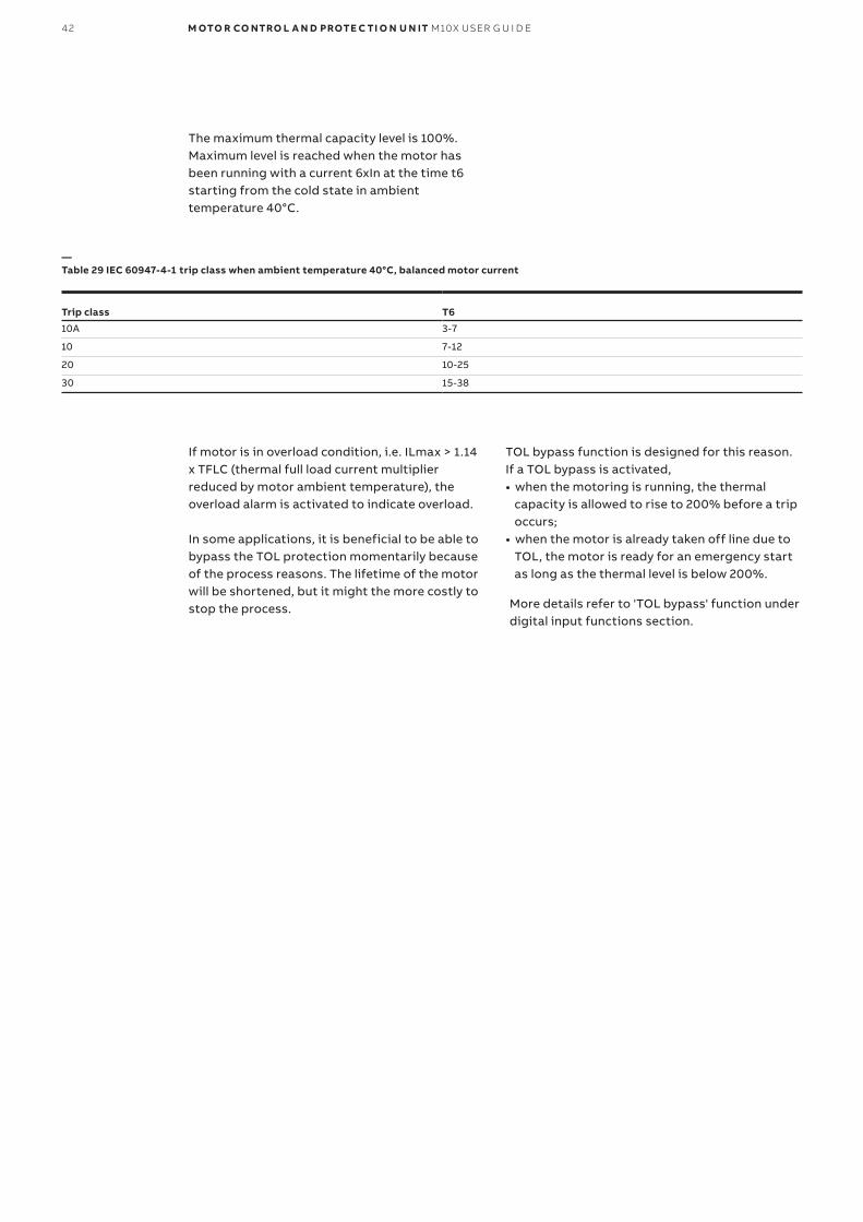
The maximum thermal capacity level is 100%. Maximum level is reached when the motor has been running with a current 6xIn at the time t6 starting from the cold state in ambient temperature 40°C.
Trip class T6
10A 3-7
10 7-12
20 10-25
30 15-38
—Table 29 IEC 60947-4-1 trip class when ambient temperature 40°C, balanced motor current
If motor is in overload condition, i.e. ILmax > 1.14 x TFLC (thermal full load current multiplier reduced by motor ambient temperature), the overload alarm is activated to indicate overload.
In some applications, it is beneficial to be able to bypass the TOL protection momentarily because of the process reasons. The lifetime of the motor will be shortened, but it might the more costly to stop the process.
TOL bypass function is designed for this reason. If a TOL bypass is activated,• when the motoring is running, the thermal capacity is allowed to rise to 200% before a trip occurs;• when the motor is already taken off line due to TOL, the motor is ready for an emergency start as long as the thermal level is below 200%.
More details refer to 'TOL bypass' function under digital input functions section.

0 5 . PR OTEC TI O N FU N C TI O NS 43
Function
Setting range 0=Disabled 1=Enabled
Default value Enabled
Step value 1
Disabled during motor startup
Setting range 0=Enabled during motor startup 1=Disabled during motor startup
Default value 0
Step value 1
Trip reset mode
Setting range 1=Auto 2=Local 3=Remote 4=Remote and local
Default value 4
Step value 1
Thermal model
Setting range 0=Standard model 1=EEX e
Default value 0
Step value 1
TOL bypass
Setting range 0=Disabled 1=Enabled
Default value Disabled
T6 (standard mode)
Setting range 3-40sec
Default value 6sec
Step value 1
Cool coefficient
Setting range 1-10
Default value 4
Step value 1
Ia/In(Eexe mode)
Setting range 1.2-8.0
Default value 5.0
Step value 0.1
Te(Eexe mode)
Setting range 5-40sec
Default value 5sec
Step value 1sec
TOL alarm level
Setting range 60-100%
Default value 90%
Step value 1%
TOL trip level
Setting range 60-100%
Default value 100%
Step value 1%
TOL reset level
Setting range 10-60%
Default value 50%
Step value 1%
Ambient temperature
Setting range 0-80°C
Default value 40°C
Step value 5°C
—Table 30 TOL protection parameters
See ' M10x parameters description' manual for parameters explanation.

44 M OTO R CO NTRO L A N D PROTE C TI O N U N IT M10X USER G U I D E
Stall protectionStall protection is used to protect the driven mechanical system from jams and excessive
overload. Stall protection function uses Imax as the criterion. There are other parameters to be determined as follows:
Function
Setting range 0=Disabled 1=Enabled
Default value 1
Step value 1
Trip reset mode
Setting range 2=Local 3=Remote 4=Remote and local
Default value 4
Step value 1
Trip level
Setting range 120-800%
Default value 400%
Step value 10%
Trip delay
Setting range 0.0-25.0sec
Default value 0.5sec
Step value 0.1sec
—Table 31 Stall protection parameters
—34 Stall protection
Stall function activates after motor nominal startup time has elapsed.
The highest measured phase current (ILmax) is compared against the trip level. When ILmax remains over the trip level at a time longer than trip delay, a stall alarm is issued and the contactor tripped.
See ' M10x parameters description' manual for parameters explanation.

0 5 . PR OTEC TI O N FU N C TI O NS 45
—35 Long start protection
Long start protectionThe long start protection protects motor against locked or stalled rotor in starting state. M10x detects the current after a start command, and
signals a fault when current continuously exceeds a separately set threshold of the period of start time.
Function
Setting range 0=Disabled 1=Enabled
Default value Disabled
Step value 1
Long start trip level (Locked rotor level)
Setting range 120-800%
Default value 120%
Step value 10%
Long start trip delay
Setting range 0-250sec
Default value 10sec
Step value 1sec
Trip reset mode
Setting range 2=Local 3=Remote 4=Remote and Local
Default value 4
Step value 1
—Table 32 Long start protection parameters
See ' M10x parameters description' manual for parameters explanation.

46 M OTO R CO NTRO L A N D PROTE C TI O N U N IT M10X USER G U I D E
Phase failure protectionM10x protects the motor against phase current loss condition. Phase failure protection function uses ILmin/ILmax (the ratio of lowest ILmin and highest
measured phase value ILmax) as the criterion. Function is suppressed by parameters Motor startup time, number of phases and Softstart ramp time.
Function
Setting range 0=Disabled 1=Enabled 3=Alarm only
Default value Disabled
Step value 1
Trip delay
Setting range 0-60sec
Default value 10sec
Step value 1s
Alarm level
Setting range 10-90%
Default value 80%
Step value 1%
Trip level
Setting range 5-90%
Default value 70%
Step value 1%
Trip reset mode
Setting range 2=Local 3=Remote 4=Remote and local
Default value 4
Step value 1
—Table 33 Phase failure parameters
—36 Phase failure protection
ILmin/ILmax is compared against the phase failure alarm level. When ILmin/ILmax decreases below the Alarm level, a “Phase failure alarm” alarm is issued.
ILmin/ILmax is compared against the phase failure trip level. When ILmin/ILmax remains below the trip level at a time longer the trip delay, a “Phase failure trip” alarm is issued and the contactor tripped.
See ' M10x parameters description' manual for parameters explanation.

0 5 . PR OTEC TI O N FU N C TI O NS 47
Function
Setting range 0=Disabled 1=Enabled 3=Alarm only
Default value Disabled
Step value 1
Trip delay
Setting range 0-60sec
Default value 10sec
Step value 1s
Alarm level
Setting range 50-90%
Default value 90%
Step value 1%
Trip level
Setting range 5-90%
Default value 85%
Step value 1%
Trip reset mode
Setting range 2=Local 3=Remote 4=Remote and local
Default value 4
Step value 1
—Table 34 Unbalance protection parameters
—37 Unbalance protection
Unbalance protectionM10x protects the motor against unbalance conditions. Unbalance protection function also
uses ILmin/ILmax as the criterion. Function is suppressed by parameters Motor startup time, Number of phases and Softstart ramp time.
ILmin/ILmax is compared against the unbalance alarm level. When ILmin/ILmax decreases below the alarm level, an unbalance alarm is issued.
ILmin/ILmax is compared against the unbalance trip level. When ILmin/ILmax remain below the trip level at a time longer the trip delay, an unbalanced trip alarm is issued and the contactor tripped.
See ' M10x parameters description' manual for parameters explanation.

48 M OTO R CO NTRO L A N D PROTE C TI O N U N IT M10X USER G U I D E
Underload protectionM10x protects the motor against underload conditions. Underload protection function uses ILmax/In (the ratio of highest measured phase value ILmax and the rated current of the motor In)
as the criterion. There are other parameters to be determined, such as alarm level, trip level and trip delay. The protection characteristic are as follows:
Function
Setting range 0=Disabled 1=Enabled 3=Alarm only
Default value Disabled
Step value 1
Alarm level
Setting range 20-90%
Default value 30%
Step value 1%
Setting range
Setting range 5-90%
Default value 20%
Step value 1%
Trip delay
Setting range 0-1800sec
Default value 10sec
Step value 1sec
Trip reset mode
Setting range 2=Local 3=Remote 4=Remote and local
Default value 4
Step value 1
—Table 35 Underload protection parameters
—38 Underload protection
The ILmax/In is compared against the underload alarm level. When ILmax/In decreases below the alarm level an underload alarm is issued.
The ILmax/In is compared against the underload trip level. When ILmax/In remains below the trip level at a time longer than underload trip delay, an underload trip alarm is issued and the contactor tripped.
See ' M10x parameters description' manual for parameters explanation.

0 5 . PR OTEC TI O N FU N C TI O NS 49
Function
Setting range 0=Disabled 1=Enabled 3=Alarm only
Default value Disabled
Step value 1
Alarm level
Setting range 5-50%
Default value 20%
Step value 1%
Trip level
Setting range 5-50%
Default value 15%
Step value 1%
Trip delay
Setting range 0-1800sec
Default value 5sec
Step value 1sec
Trip reset mode
Setting range 2=Local 3=Remote 4=Remote and local
Default value 4
Step value 1
—Table 36 Noload protection parameters
—39 Noload protection
Noload protectionM10x protects the motor against no load conditions. Practically, noload protection is the
same function as underload protection. The function also uses ILmax/In as the criterion.
The ILmax /In is compared against the no load alarm level. When ILmax/In decreases below the alarm level a noload alarm is issued.
The ILmax/In is compared against the noload trip level. When ILmax/In remains below the trip level at a time longer than noload trip delay, a noload trip alarm is issued and the contactor tripped.
See ' M10x parameters description' manual for parameters explanation.
50 M OTO R CO NTRO L A N D PROTE C TI O N U N IT M10X USER G U I D E
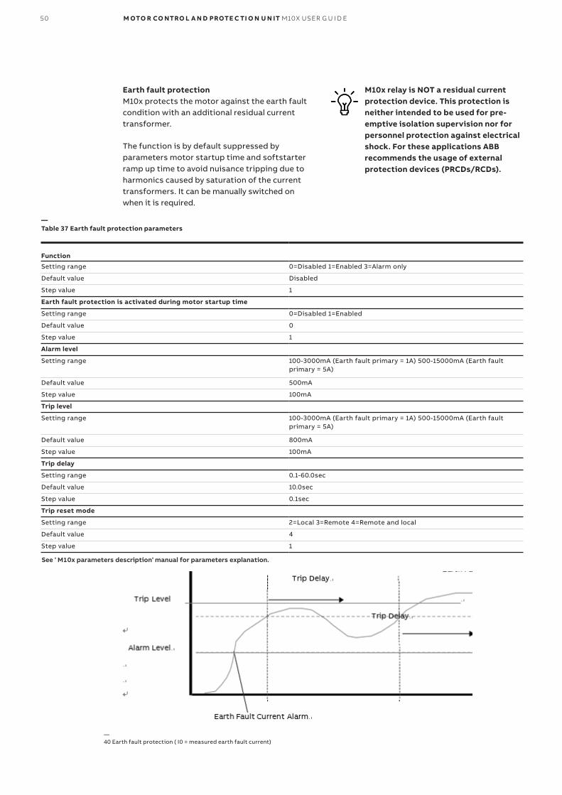
Earth fault protectionM10x protects the motor against the earth fault condition with an additional residual current transformer.
The function is by default suppressed by parameters motor startup time and softstarter ramp up time to avoid nuisance tripping due to harmonics caused by saturation of the current transformers. It can be manually switched on when it is required.
M10x relay is NOT a residual current protection device. This protection is neither intended to be used for pre-emptive isolation supervision nor for personnel protection against electrical shock. For these applications ABB recommends the usage of external protection devices (PRCDs/RCDs).
Function
Setting range 0=Disabled 1=Enabled 3=Alarm only
Default value Disabled
Step value 1
Earth fault protection is activated during motor startup time
Setting range 0=Disabled 1=Enabled
Default value 0
Step value 1
Alarm level
Setting range 100-3000mA (Earth fault primary = 1A) 500-15000mA (Earth fault primary = 5A)
Default value 500mA
Step value 100mA
Trip level
Setting range 100-3000mA (Earth fault primary = 1A) 500-15000mA (Earth fault primary = 5A)
Default value 800mA
Step value 100mA
Trip delay
Setting range 0.1-60.0sec
Default value 10.0sec
Step value 0.1sec
Trip reset mode
Setting range 2=Local 3=Remote 4=Remote and local
Default value 4
Step value 1
—Table 37 Earth fault protection parameters
—40 Earth fault protection ( I0 = measured earth fault current)
See ' M10x parameters description' manual for parameters explanation.

0 5 . PR OTEC TI O N FU N C TI O NS 51
Function
Setting range 0=Disabled 1=Enabled 3=Alarm only
Default value Disabled
Step value 1
PTC Alarm level
Setting range 1000-10000Ω
Default value 1600Ω
Step value 1Ω
PTC trip level
Setting range 1000-10000Ω
Default value 3600Ω
Step value 1Ω
PTC trip delay
Setting range 1-1800sec
Default value 1sec
Step value 1sec
—Table 38 PTC protection parameters
PTC protection (M102 only)PTC protection protects the motor against too-high temperature by using PTC-sensor embedded
in the stator winding or the bearings. For M102, use a type A temperature sensor with a characteristic curve according to IEC 60947-8.
Function
PTC reset level
Setting range 100-10000Ω
Default value 1600Ω
Step value 1Ω
PTC trip reset mode
Setting range 1=Auto 2=Local 3=Remote 4=Remote and local
Default value 4
Step value 1
PTC short circuit alarm level
Setting range 0-250Ω
Default value 10 Ω
Step value 1 Ω
See ' M10x parameters description' manual for parameters explanation.

52 M OTO R CO NTRO L A N D PROTE C TI O N U N IT M10X USER G U I D E
—41 PTC protection
The resistance of PTC input is compared against the alarm level. When resistance of PTC input exceeds above the alarm level, a PTC alarm message is issued.
The resistance of the PTC input is compared against the trip level. When resistance of PTC in-put is above the trip level PTC trip alarm is is-sued and the contactor tripped.
After PTC trip is executed, the resistance of PTC input is compared against the PTC reset level. When resistance of PTC input decreases below the reset level, the PTC protection function executes the function set by PTC reset mode.
When the resistance of PTC input exceeds 12kΩ, a PTC open circuit alarm message is issued.
Short circuit and open circuit detection threshold have no fault time delay. The short circuit and open circuit protection is enabled when PTC protection is enabled, and cannot be disabled.
If the measured resistance is over 20kΩ, thermistor resistor will only display " 20kΩ".
The distance between PTC sensors and M10x PTC measuring inputs cannot exceed the following to be able to maintain reasonable reading:
Cross section Length
2.5mm2 2x250m
1.5mm2 2x150m
0.5mm2 2x50m
M10x provides short circuit and open circuit detection for the temperature sensing element. Short circuit alarm level is settable, and open circuit alarm level is fixed. When the resistance
of PTC input falls below short circuit alarm level, a PTC short circuit alarm message is issued.
—Table 39 PTC Sensor distance vs cable size
0 5 . PR OTEC TI O N FU N C TI O NS 53
Start limitationStart limitation helps to protect the motor and also the process against excess number of starts in a given interval. When the number of starts is reached and the motor is switched off, a new start is prevented. The time interval, starts from the first start. After the elapse of the time interval, the counter is reset to the preset value. The permissible motor starts per hour can be obtained from the manufacturer's motor and apparatus data sheet. However, the minimum waiting time between two starts must be observed.
The parameterization of the protection function can be the number of starts per time interval or the time between two consecutive starts. In the first case, the user must wait after the trip for the reset to take place before making a start.
If motor data specifies the number of starts during a certain time span, this function can be used to supervise the number of starts. In some other cases, the process may require a motor start number, which the protection can provide.
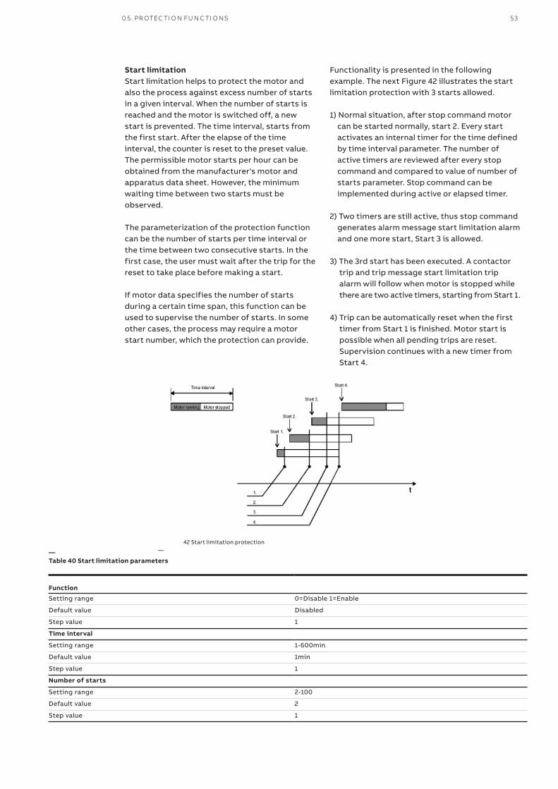
Functionality is presented in the following example. The next Figure 42 illustrates the start limitation protection with 3 starts allowed.
1) Normal situation, after stop command motor can be started normally, start 2. Every start activates an internal timer for the time defined by time interval parameter. The number of active timers are reviewed after every stop command and compared to value of number of starts parameter. Stop command can be implemented during active or elapsed timer.
2) Two timers are still active, thus stop command generates alarm message start limitation alarm and one more start, Start 3 is allowed.
3) The 3rd start has been executed. A contactor trip and trip message start limitation trip alarm will follow when motor is stopped while there are two active timers, starting from Start 1.
4) Trip can be automatically reset when the first timer from Start 1 is finished. Motor start is possible when all pending trips are reset. Supervision continues with a new timer from Start 4.
—42 Start limitation protection
Function
Setting range 0=Disable 1=Enable
Default value Disabled
Step value 1
Time interval
Setting range 1-600min
Default value 1min
Step value 1
Number of starts
Setting range 2-100
Default value 2
Step value 1
—Table 40 Start limitation parameters

54 M OTO R CO NTRO L A N D PROTE C TI O N U N IT M10X USER G U I D E
Function Enable/Disable
Setting range 0=Disable 1=Enable
Default value Disabled
Step value 1
Trip Reset Mode
Setting range 2=Local 3=Remote 4=Remote&Local
Default value 4
Step value 1
—Table 41 Phase sequence protection parameters
the phase sequence of current. The definition of correct phase sequence:• Voltage: L1, L2, L3• Current: la, lb, lc
If enable phase sequence protection, when M10x detects the voltage or current is different from the definition M10x will release a phase sequence trip signal.
See ' M10x parameters description' manual for parameters explanation.
Phase Sequence M10x protects the motor against connection in wrong phase sequence. Before motor startup, M10x detects the phase sequence of voltage con-tinuously and after startup M10x will detect
Undervoltage protection (M102 Only)M102 protects the motor against undervoltage conditions such as voltage dip.
The undervoltage protection function uses ULmin as the criterion. There are other parameters to be determined, such as alarm level, trip level and trip delay, and reset voltage level. The protectioncharacteristic is as follows:
The lowest measured main line voltage (Ulmin) is compared against the undervoltage alarm level. When Ulmin decreases below the undervoltage alarm level, an undervoltage alarm is issued.
The lowest measured main line voltage (Ulmin) is compared against the undervoltage trip level and voltage restore level. When Ulmin recovers above undervoltage restore level before trip delayexpires and motor continues running. If Ulminremains below the restore level at a time longer than trip delay, undervoltage trip is issued and contactor will be opened.
When autorestart function is active, undervoltage trip delay time is no longer required to be configured as it is the same as the setting value of maxi-mum power down time.
If “main switch” is detected on ‘pow-ered off’ position, undervoltage alarm/tip function is suppressed to avoid unnecessary annunciationwhile the voltage measurement is still active.

0 5 . PR OTEC TI O N FU N C TI O NS 55
Function
Setting range 0=Disabled 1=Enabled 3=Alarm only
Default value Disabled
Step value 1
Alarm level
Setting range 50-100%
Default value 80%
Step value 1%
Trip level
Setting range 30-100%
Default value 65%
Step value 1%
Trip delay
Setting range 0.2-5.0sec
Default value 1.0sec
Step value 0.1sec
Reset level
Setting range 50-100%
Default value 90%
Step value 1%
Trip reset mode
Setting range 1=Auto 2=Local 3=Remote 4=Remote and local
Default value 4
Step value 1
—Table 42a Undervoltage protection parameters
See ' M10x parameters description' manual for parameters explanation.
—43 Undervoltage protection

56 M OTO R CO NTRO L A N D PROTE C TI O N U N IT M10X USER G U I D E
Autorestart After a sudden voltage dip , M102 may restart the
motor in 4 different ways depending on the type
and duration of the dip(s) through two setting
modes, i.e. standard mode and enhanced mode.
Function
Setting range 0=Disabled 1=Enabled
Default value Disabled
Step value 1
Function mode
Setting range 0=standard 1=enhanced
Default value 0
Step value 1
Maximum autoreclose time
Setting range 0-5000msec
Default value 200msec
Step value 100msec
Maximum powerdown time
Setting range 0-1200sec
Default value 5sec
Step value 0.1sec
Staggered start delay
Setting range 0-1200sec
Default value 5sec
Step value 0.1sec
—Table 42b Auto restart function parameters
See ' M10x parameters description' manual for parameters explanation.
Voltage dip trigger level and reset
level correspond to the settings of un-
dervoltage trip level and reset level .
Standard modeUnder standard mode, the reaction of the auto
restart function depends on the length of the volt-age dip. Three scenarios (cases) are considered,
Case 1: Voltage dip< autoreclose time.
—44 Autorestart (Voltage dip< autoreclose time)

0 5 . PR OTEC TI O N FU N C TI O NS 57
Case 2: Autoreclose time<voltage dip< Maximum powerdown time.
—45 Autorestart (autoreclose time<voltage dip< Maximum powerdown time)
—46 Restart (Voltage dip> Maximum powerdown time)
If power is restored after autoreclose time but before maximum powerdown time, motor will be restarted after the staggered start delay time.
Case 3: Voltage dip> Maximum powerdown time.
If supply voltage remains below restore level long enough and exceeds maximum powerdown time, no automatic restart will be initiated.

58 M OTO R CO NTRO L A N D PROTE C TI O N U N IT M10X USER G U I D E
—47 Restart (2xdip<200ms within 1sec)
Enhanced Mode
In the enhanced mode, the reaction of the autorestart function not only depends on the length of the voltage dip, but also the number of voltage dips within a short period of time.
Enhanced mode includes all 3 cases listed in stan-dard mode. In addition, case 4 is supported.
Case 4: 2xdip<200ms within 1sec
Under case 4 scenario, two voltages dips may
occur within 1 seconds. Each dip is shorter than
200ms. The device shall be able to react and trig-
ger a delay restart after the second voltage dip
recovers.
Failsafe functionalityM10x failsafe function supervises the communi-cation network interface and connection to the remote devices controlling the motor/starter equipment. The network supervision on M10x is based on no data exchange detected within the pre-configured delay time (1~25s) which may be different from the network supervision on control system level.
If the device falls into failsafe mode, the pre-
configured failsafe action will be followed. The
options of the failsafe action are,
- Motor stay as it is ( No operation);
- Start the motor (Start 1);
- Start the motor in reverse direction (Start2);
- Trip the motor (Trip).
Under failsafe mode, the motor control access falls to local control regardless of previous settings. Both control from hardwiring (to local controlpanel or on starter) and MDx panel are active under failsafe mode. Once the network is restored, the control access recovers to the previous setting, the tripping message 'communication failure' is automatically reset.
To disable the network supervision function from M10x, set the communica-tion failure delay time as '255"
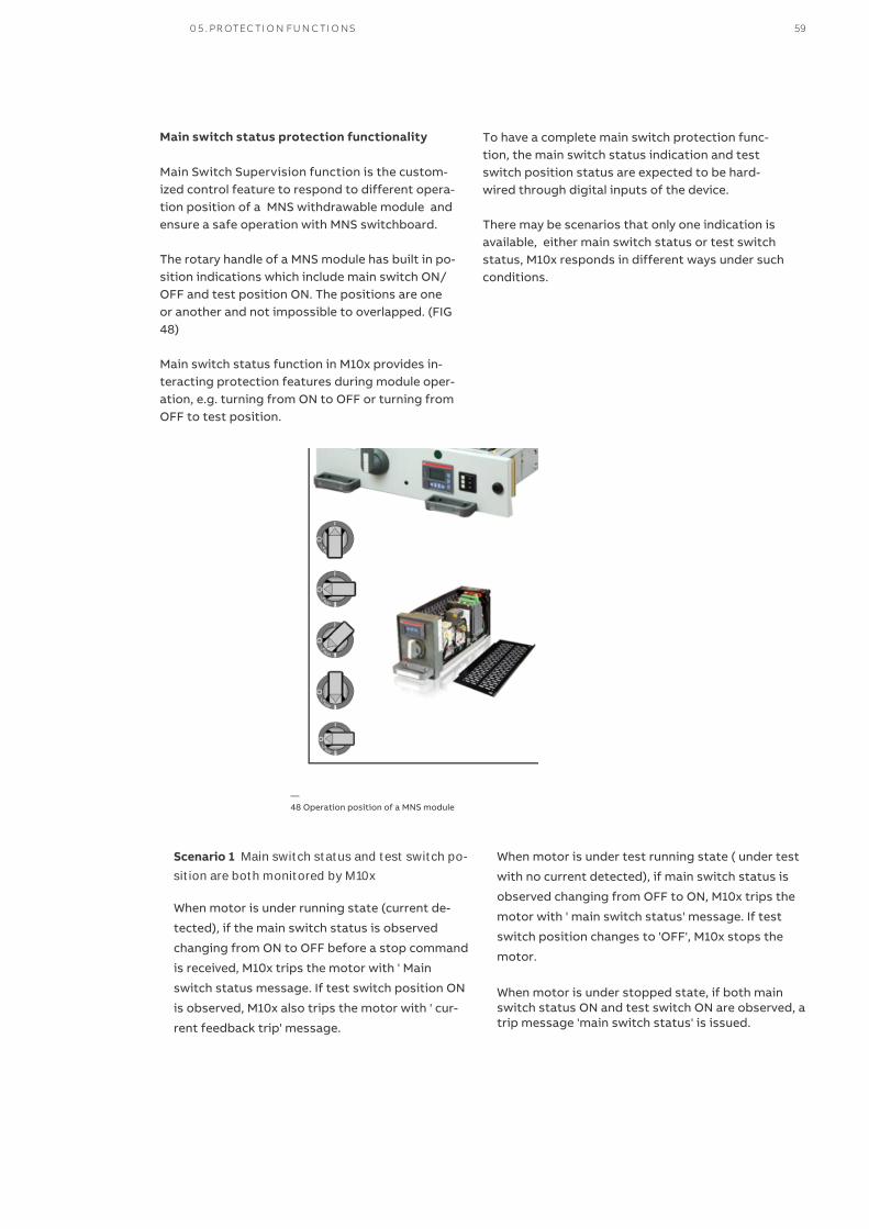
Main switch status protection functionality
Main Switch Supervision function is the custom-ized control feature to respond to different opera-tion position of a MNS withdrawable module and ensure a safe operation with MNS switchboard.
The rotary handle of a MNS module has built in po-sition indications which include main switch ON/ OFF and test position ON. The positions are oneor another and not impossible to overlapped. (FIG 48)
Main switch status function in M10x provides in-teracting protection features during module oper-ation, e.g. turning from ON to OFF or turning from OFF to test position.
—48 Operation position of a MNS module
To have a complete main switch protection func-tion, the main switch status indication and test switch position status are expected to be hard-wired through digital inputs of the device.
There may be scenarios that only one indication is available, either main switch status or test switch status, M10x responds in different ways under such conditions.
Scenario 1 Main switch status and test switch po-
sition are both monitored by M10x
When motor is under running state (current de-
tected), if the main switch status is observed
changing from ON to OFF before a stop command
is received, M10x trips the motor with ' Main
switch status message. If test switch position ON
is observed, M10x also trips the motor with ' cur-
rent feedback trip' message.
When motor is under test running state ( under test
with no current detected), if main switch status is
observed changing from OFF to ON, M10x trips the
motor with ' main switch status' message. If test
switch position changes to 'OFF', M10x stops the
motor.
When motor is under stopped state, if both main switch status ON and test switch ON are observed, a trip message 'main switch status' is issued.
0 5 . PR OTEC TI O N FU N C TI O NS 59

Soft test switch is the function
available through parameter configu-ration. It is used to simulate module intest position. Similar as ‘Test Switch’function, when ‘Soft test switch’ pa-rameter is selected, M10x switches offcurrent and voltage based protectionfunctions regardless the protectionsettings. A ‘T’ symbol is displayed onMD panel when soft test switch is se-lected.
Under main switch OFF position,undervoltage alarm/tip function issuppressed to avoid unnecessary an-nunciation
Scenario 2 Only main switch status is monitoredwith no test switch hardwired
When motor is under running state (current de-
tected), if the main switch status is observed
changing from ON to OFF before a stop command
is received, M10x trips the motor with ' Main
switch status message. If the soft test switch
function is enabled during motor running, M10x
also trips the motor with ' current feedback trip'
message.
When motor is under test running state through
soft test switch function, , if main switch status is
observed changing from OFF to ON, M10x trips
the motor with ' main switch status' message. If
test switch position changes to 'OFF', M10x stops
the motor.
When motor is under stopped state, if both main
switch status ON and test switch ON are ob-
served, a trip message 'main switch status' is is-
sued.
Scenario 3 Main switch status is not monitored,
test switch is monitored
This becomes a test position feature only.
Aligned with MNS module handle design, under test position means that the control circuit is pow-ered up while the power circuit being disconnected so that the control functionstesting can be conducted. Once ‘test’ position is detected through the DI, M10x switches off current and voltage based protection functions re-gardless the protection settings. A ‘T’ symbol is displayed on MD panel when ‘test’ position is detected. Once ‘test’ position is off, all protections restore automatically.
60 M OTO R CO NTRO L A N D PROTE C TI O N U N IT M10X USER G U I D E

—06. Control Access
Control authorityM10x control authority is the term describing the privileges allowing motor control operation through M10x. It is also a setting parameter in M10x to define which control access group has privileges to operate the motor via M10x.
Control groupsThere are three control access groups defined in M10x:• Local hardwiring: M10x accepts its start1/ start2/stop commands from the hardwired inputs• Remote fieldbus: M10x accepts its start1/ start2/stop commands from a PLC or higher control system via fieldbus, ie, MODBUS or PROFIBUS.• MDx control: M10x accepts its start1/start2/ stop commands from operator panel MDx located on the front panel of each starter unit on switchgear.
Assign control accessTo decide which of above 3 control groups may have the control access , the selector switch func-tion will have to be used. There are two type of se-lector switch functions in M10x, the local selector switch and the soft selector switch function.
When soft selector switch is used, the control ac-cess is assigned to the control groups through configuration. Which means the control access have to be pre-configured and can only be changed via parameters.. (Fig 49).
In Profibus version, i.e. M10x-P, M10x also supports the soft selector switch from Profibus. (Fig 50).
In most applications, a physical local selector switch is installed beside motor or on the starter to select the control access. In M10x, the local se-lector switch is supported via hardwiring into DIs. (Fig 51). Local selector switch always has the high-est control privilege out of all.
—49 Parameter setting of local/remote of control authority
Soft selector switch via parameter settingWhen using soft selector switch, users define the control access directly through configuration. No actual switch is used.
0 6 .CO NTR O L ACCE SS 61

—50 Enable PROFIBUS option
Soft selector switch via Profibus DP
Once the 'Profibus Auto Mode Active' option is se-lected through parameter configuration, the con-trol access is decided by the auto bit through Profibus cyclical data exchange.
MDx control can be pre-assigned to either local con-trol or remote control. (Fig 50)
Local selector switchM10x supports hardwired local selector switch function which allows selecting control
access groups via hardwired inputs. To enable this function, one of the digital inputs has to be defined as ‘Loc/R’ in M10x (Fig. 51).
—51 Enable local selector switch
When “Loc/R” selector switch func-
tion is assigned to the DI, soft selector option is no longer available.
62 M OTO R CO NTRO L A N D PROTE C TI O N U N IT M10X USER G U I D E
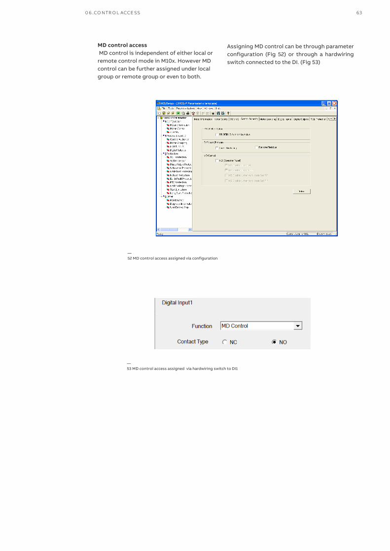
—41 Assign local/remote function to digital input
—52 MD control access assigned via configuration
MD control access MD control is independent of either local or remote control mode in M10x. However MD control can be further assigned under local group or remote group or even to both.
Assigning MD control can be through parameter configuration (Fig 52) or through a hardwiring switch connected to the DI. (Fig 53)
—53 MD control access assigned via hardwiring switch to DI1
0 6 .CO NTR O L ACCE SS 63
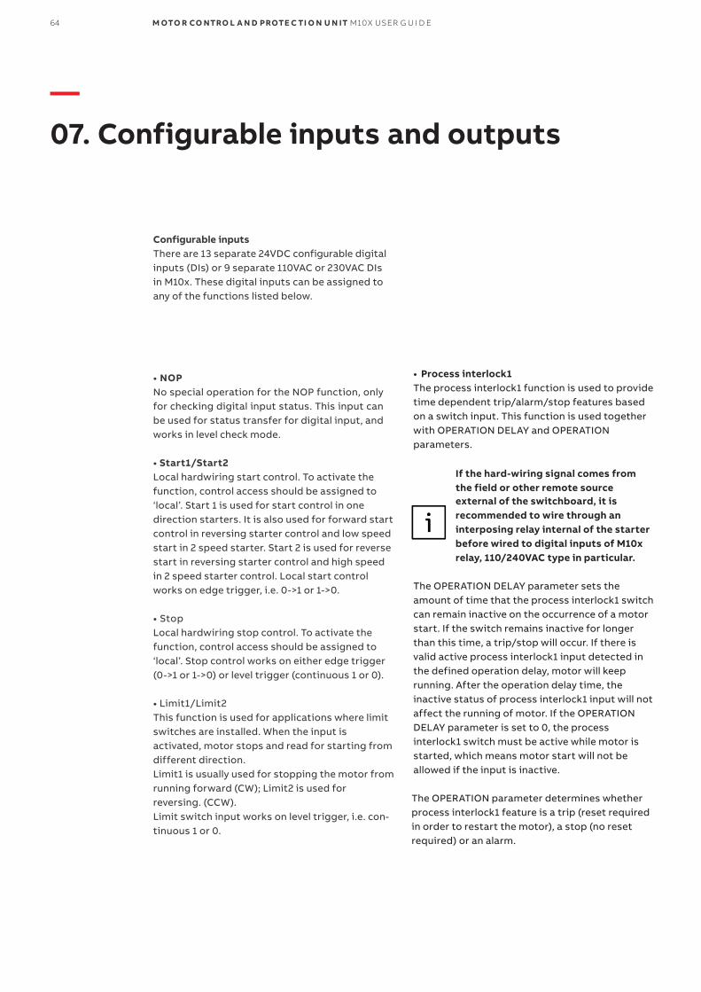
64 M OTO R CO NTRO L A N D PROTE C TI O N U N IT M10X USER G U I D E
—07. Configurable inputs and outputs
• NOPNo special operation for the NOP function, only for checking digital input status. This input can be used for status transfer for digital input, and works in level check mode.
• Start1/Start2Local hardwiring start control. To activate the function, control access should be assigned to ‘local’. Start 1 is used for start control in one direction starters. It is also used for forward start control in reversing starter control and low speed start in 2 speed starter. Start 2 is used for reverse start in reversing starter control and high speedin 2 speed starter control. Local start control works on edge trigger, i.e. 0->1 or 1->0.
• StopLocal hardwiring stop control. To activate the function, control access should be assigned to ‘local’. Stop control works on either edge trigger (0->1 or 1->0) or level trigger (continuous 1 or 0).
• Limit1/Limit2This function is used for applications where limit switches are installed. When the input isactivated, motor stops and read for starting from different direction.Limit1 is usually used for stopping the motor from running forward (CW); Limit2 is used forreversing. (CCW).Limit switch input works on level trigger, i.e. con-tinuous 1 or 0.
• Process interlock1The process interlock1 function is used to provide time dependent trip/alarm/stop features based on a switch input. This function is used together with OPERATION DELAY and OPERATION parameters.
If the hard-wiring signal comes from the field or other remote source external of the switchboard, it is recommended to wire through an interposing relay internal of the starter before wired to digital inputs of M10x relay, 110/240VAC type in particular.
The OPERATION DELAY parameter sets the amount of time that the process interlock1 switch can remain inactive on the occurrence of a motor start. If the switch remains inactive for longer than this time, a trip/stop will occur. If there is valid active process interlock1 input detected in the defined operation delay, motor will keep running. After the operation delay time, the inactive status of process interlock1 input will not affect the running of motor. If the OPERATION DELAY parameter is set to 0, the process interlock1 switch must be active while motor is started, which means motor start will not be allowed if the input is inactive.
The OPERATION parameter determines whether process interlock1 feature is a trip (reset required in order to restart the motor), a stop (no reset required) or an alarm.
Configurable inputsThere are 13 separate 24VDC configurable digital inputs (DIs) or 9 separate 110VAC or 230VAC DIs in M10x. These digital inputs can be assigned to any of the functions listed below.

07.CO N FI G U R A B L E INPUTS AND OUTPUTS 65
—54 Process interlock1
Case 1: When t1>t2, motor can run normally.
Case 2: When t1<t2, a trip or stop will be performed according to the predefined operation.
Process interlock works on level
check mode which means once the in-
terlock is activated, motor is locked
down until the interlock changes to
deactivated.
Process interlock may cause motor to
trip when activated. Once it is deacti-
vated, the trip is reset automatically.
• Process interlock2Similar as process interlock 1, process interlock 2 provides a time dependent trip/alarm/stop fea-tures based on a switch input. Different from process interlock 1, process interlock works on the complete motor operation process which in-clude starting period, running period and stop.
The related parameters to process interlock 2 are the same as process interlock 1.
• Emergency stopThis input is used for the emergency stop device. When the input is active, the motor will be stopped/tripped and cannot be restarted until the input is inactive. This function is used together with OPERATION parameters.
OPERATION: This parameter determines whether the emergency stop feature is a trip (reset required in order to restart the motor) or a stop (no reset required).
Emergency stop function is not used for functional safety.
• PLC control 1 & PLC control 2'PLC control 1' & 'PLC control 2' determine jogging control through the digital input. When DI detects an active signal, the motor will run continuously on one direction or at one speed until the inactive signal in detected to stop the motor.
'PLC control 1' is designed for start/stop forward control (CW) or first speed control in two speed starters.
'PLC control 2' is designed for start/stop reverse control (CCW) or second speed control in two speed starters.
To enabled PLC control function (jogging control), local control access has to be enabled.
• Trip resetThe input is used to reset a trip. This input works in edge triggering mode.
• Torque switchThis input is used to check the status of torque switch used for actuator starter. When the inputis different from normal state, M10x will releaseall contactor control relays to stop the motor. This input works in level check mode.
• F_CAThe F_CA input is the feedback detection signal of contactor control relay CCA. This input works in level check mode.
• F_CBThe F_CB input is the feedback detection signal of contactor control relay CCB. This input works in level check mode.
• F_CCThe F_CC input is the feedback detection signal of contactor control relay CCC. This input works in level check mode.
• Loc/RThe Loc/R input is local/remote control switch input.
Once the DI is assigned as loc/R function, a local selector switch function is activated. The local se-lector switch has the highest privilege to assign control access. This input works in level check mode.
• Main Switch SupervisionWhen ‘main switch status‘ input is selected, main switch protection function will be enabled. Refer to the description of main switch protection function.This input works in level check mode.
• External tripThe input is used for tripping motor from external triggers. For example, a trip signal from short circuit protection device. The input requires to be reset after external trip, either from local or from remote. The input works on level trigger, i.e. continuous '0" or "1".
In feeder mode, ‘External trip’ function only occurs a message and details refer to ‘Feeder’ chapter on page 38.
66 M OTO R CO NTRO L A N D PROTE C TI O N U N IT M10X USER G U I D E

07.CO N FI G U R A B L E INPUTS AND OUTPUTS 67
• TOL BypassWhen DI is defined as ‘TOL Bypass’, the input is used to decide when to activate or deactivate ‘TOL Bypass Function’.
TOL bypass function is the function that allow TOL tripping level rise temporarily to 200% when it is activated. That is, when TOL bypass function is activated, a motor is allowed to continue running until thermal capacity level reaches 200% without tripping on TOL and a motor tripped on TOL is allowed to be restarted immediately in case of emergency, regardless the thermal level.
To activate TOL bypass function, the parameter ‘TOL bypass” is required to be enabled. The operation of TOL bypass function is from a special "TOL Bypass " command either through local control signals (via digital input hard-wiring) or given by fieldbus.
If the command comes from local control DIs, depending on the DI setting, a continuous "0" or "1" activate the TOL bypass function. A reserve signal de- activate the function.
If the command comes from PROFIBUS, a continuous "1" from PROFIBUS activate the function until a '0" is received.
If the command comes from MODBUS, an"activate TOL bypass" command activate the function and a 'deactivate TOL bypass' command deactivate the function.
A sequence of activating and deactivating a TOL bypass function via DI is described as following,
• Select parameter ‘TOL bypass’ under TOL protection section if the motor is expected to be run exceeding 100% thermal level in case of emergency; • Wire a ‘TOL bypass’ control switch to the DI and define the DI as ‘TOL bypass’; • Switch on motor and run normally; • In case of emergency, activate TOL bypass function through the DI and increase the TOL level; • After the emergency situation, de-activate the function through DI to recover TOL protection.
TOL bypass function increases thermal capacity level and can cause equipment overheating and fire. The function must be limited to applications where temporarily thermal increase or immediate restart are vital.
• MD controlMD control is used to decide whether the control command from MD is active or not. When one of the digital inputs is assigned as MD control, the
control authority of MD will not be changed via parameterization but depend on the input status of the DI. If the input status is active, motor can be controlled via MD and vice versa.
Although above listed functionsare available to all 13 DI configura-tion, there are certain functionswhich should only be assignedonce to one of the DIs only. Thesefunctions include, Limit1,Limit2,PLC control1/2, F_CA, F_CB, F_CC,Loc/ R, and Main switch status

•Configurable inputs type definition
Trigger mode Contactor type Function Description
Edge triggering NO, NC Start1 If the input status is different than the setting, the function will
be active.Start2
Stop*
Trip reset
PLC control1
PLC control2
Level triggering NO, NC Process interlock1 If the input status is the same as the setting, the function will be
active.
Emergency stop If the input status is different than the setting, the function will
be active.Torque switch
Process interlock2
MD control
Test switch
External trip
Stop *
TOL Bypass
NOP Only detects the input status.
—Table 43 Operation character of configurable inputs
* Options of edge trigger type or level trigger type are available for 'stop' command.
Configurable outputs
In addition to three contactor control relays, there are another two sets of configurable output re-lays available in M102 model. As for M101 product type, two sets of contactor control relays and one set of configurable output relay are provided.
Similar as for configurable digital inputs, a wide
range of functions are available to be configured
to any of the digital outputs.
The contact status of the output re-
lays are not monitored by M10x
68 M OTO R CO NTRO L A N D PROTE C TI O N U N IT M10X USER G U I D E

07.CO N FI G U R A B L E INPUTS AND OUTPUTS 69
• Energize on motor start delay:Provides a delayed energization of relay when motor is started.
• De-energize on motor stop delay:Provides a delayed de-energization of relay when motor is stopped.
• Fieldbus control:The relay can be energized or de-energized via the serial port.
• DI9 /DI 10/DI 11 status (M10x 24VDC type):The relay energizes on DI9/DI 10/DI11 status "1"
• DI0/DI1/DI2 status(M10x AC type ):The relay energizes on DI0/DI 1/DI2 status "1"
• Trips:This is a general trip indication function which include the trips initiated across different motor states, i.e. motor running, stopped and at fault. The relay is activated when a trip occurs while motor is running. The relay is also activated to the faults which are detected during motor stopped, e.g. undervoltage happens while motor isstopped or an external trip (through DI) which is received during motor stopped. The relay remains activated while motor is at fault and will not recovered until the trip source is removed. The relay is configurable as energized type or de-energized type.
• Specific trip function:The output can be assigned with specific trip function including TOL, Earth fault trip, Stalled rotor trip, Phase failure trip. Phase unbalance trip, Under-load trip, No-load trip, PTC trip, Under-voltage trip, Start limitation trip, Long start trip, Phase sequence trip.
• Alarms:This is a general alarm function. The relay is energized or de-energized whenever an alarm occurs.
• Specific alarm function:The output can be assigned with specific alarm function including TOL, Earth fault alarm, over-load alarm, Phase failure alarm. Phase unbalance alarm, Under-load alarm, No-load Alarm, PTC alarm, PTC short circuit alarm, PTC open circuit alarm, Under-voltage alarm, Start limitation alarm, Under-voltage alarm, Auto-reclose alarm.
• Watchdog output:M10x has an internal hardware watchdog supervising the behavior of the microprocessor software. Digital output can be used as signaling output relay for indicating the status of the unit’s internal watchdog.
• Communication failure:When a failure occurs, the relay can be set to energized or de-energized via parameterization.
• Contactor welded:When contactor welded occurs, the relay can be set to energized or de- energized via parameterization.
• RCU mode (M101 only):This definition is assigned to the programmable output when NR DOL/RCU, REV DOL/RCU or contactor feeder/RCU is selected as the motor start mode. The relay output serves the same function of de-energizing the contactor coil as CCC output in M102.
• Local_remote output:The relay is energized when the control authority is remote only. The relay will be de-energized when the control authority is local.
• Ready to start:The relay will energized when the module is not at fault, not running and ready for a start.
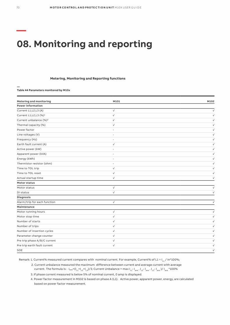
—08. Monitoring and reporting
Metering, Monitoring and Reporting functions
Metering and monitoring M101 M102
Power information
Current L1,L2,L3 (A) √ √
Current L1,L2,L3 (%)1 √ √
Current unbalance (%)2 √ √
Thermal capacity (%) √ √
Power factor - √
Line voltages (V) - √
Frequency (Hz) - √
Earth fault current (A) √ √
Active power (kW) - √
Apparent power (kVA) - √
Energy (kWh) - √
Thermistor resistor (ohm) - √
Time to TOL trip √ √
Time to TOL reset √ √
Actual startup time √ √
Motor status
Motor status √ √
DI status √ √
Diagnosis
Alarm/trip for each function √ √
Maintenance
Motor running hours √ √
Motor stop time √ √
Number of starts √ √
Number of trips √ √
Number of insertion cycles √ √
Parameter change counter √ √
Pre trip phase A/B/C current √ √
Pre trip earth fault current √ √
SOE √
—Table 44 Parameters monitored by M10x
Remark: 1. Current% measured current compares with nominal current. For example, Current% of L1 = IL1 / In*100%;
2. Current unbalance measured the maximum difference between current and average current with average current. The formula is : Iave=(IL1+IL2+IL3)/3; Current Unbalance = max IL1- Iave , IL2- Iave , IL3- Iave )/ Iave *100%
3. If phase current measured is below 5% of nominal current, 0 amp is displayed.
4. Power factor measurement in M102 is based on phase A (L1). Active power, apparent power, energy, are calculated
based on power factor measurement.
70 M OTO R CO NTRO L A N D PROTE C TI O N U N IT M10X USER G U I D E
Functionality of maintenance functions is based on the parameters given by user. Functions operate independently so that maintenance functions can be active and alarms can be given at the same time.
Number of startsM10x counts number of starts. For each operation cycle, M10x updates the number of operating cycles in a memory map. When the start number alarm level is exceeded, M10x issues an alarm.
Motor running timeM10x counts motors running hours. When the running hours limit is crossed, M10x issues a “running time” alarm.
Insertion cycles supervisionM10x gets the value of insertion cycles via counting control power cycles. When times of Insertion cycles exceeds alarm level, M10x issues an alarm.
M10x records operation and events to assist in trouble shooting and reporting.
Number of tripsM10x counts number of trips and updates them in a memory map.
Parameter change counterM10x counts times of parameter change and updates them in a memory map.
SOEM102 provides sequence of event recorder data
for up to 256 events with time stamp.
M102 has an internal clock which pro-vides a time stamp during event recording. To ensure a correct time stamping, the internal clock shall be set correctly before operation starts.
There are three methods to set the clock- 1) Manually set the time via MD21 panel; 2) Synchronize the time using MCUSetup software; 3) Syn-chronize the time through communication network.
In case of M10x-TCP, time synchroniz-ing is expected from SNTP server to EM01 interface before further broad-casting to M10x.
Maintenance and reporting functionsM10x monitors motor and motor starter service
condition to assist users to schedule service and
maintenance of the equipment.
07.CO N FI G U R A B L E INPUTS AND OUTPUTS 71

72 M OTO R CO NTRO L A N D PROTE C TI O N U N IT M10X USER G U I D E
MD21/MD31 operator panel
OverviewM10x devices provide operator panels as optional accessories for local operation and setting parameters for individual motor starters.Two types are available MD21 (Fig 55) and MD31(Fig56).
The operator panel is connected to the main M10x device via RJ11 interface (RS485 port).
—55 MD21 operator panel
—56 MD31 operator panel
—09. Operator panel MDx
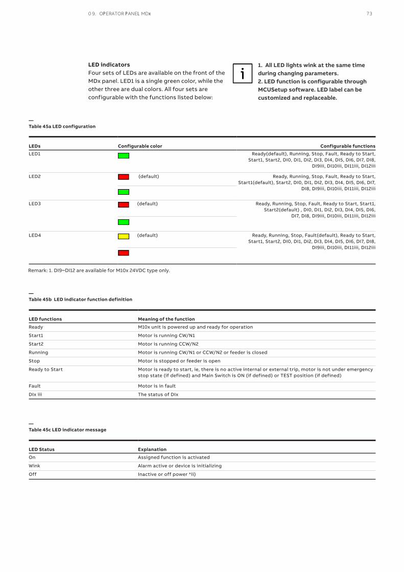
0 9. OPERATOR PANEL MDx 73
LED indicatorsFour sets of LEDs are available on the front of the MDx panel. LED1 is a single green color, while the other three are dual colors. All four sets are configurable with the functions listed below:
LEDs Configurable color Configurable functions
LED1 Ready(default), Running, Stop, Fault, Ready to Start, Start1, Start2, DI0, DI1, DI2, DI3, DI4, DI5, DI6, DI7, DI8,
DI9iii, DI10iii, DI11iii, DI12iii
LED2 (default) Ready, Running, Stop, Fault, Ready to Start, Start1(default), Start2, DI0, DI1, DI2, DI3, DI4, DI5, DI6, DI7,
DI8, DI9iii, DI10iii, DI11iii, DI12iii
LED3 (default) Ready, Running, Stop, Fault, Ready to Start, Start1, Start2(default) , DI0, DI1, DI2, DI3, DI4, DI5, DI6,
DI7, DI8, DI9iii, DI10iii, DI11iii, DI12iii
LED4 (default) Ready, Running, Stop, Fault(default), Ready to Start, Start1, Start2, DI0, DI1, DI2, DI3, DI4, DI5, DI6, DI7, DI8,
DI9iii, DI10iii, DI11iii, DI12iii
LED functions Meaning of the function
Ready M10x unit is powered up and ready for operation
Start1 Motor is running CW/N1
Start2 Motor is running CCW/N2
Running Motor is running CW/N1 or CCW/N2 or feeder is closed
Stop Motor is stopped or feeder is open
Ready to Start Motor is ready to start, ie, there is no active internal or external trip, motor is not under emergency stop state (if defined) and Main Switch is ON (if defined) or TEST position (if defined)
Fault Motor is in fault
DIx iii The status of DIx
LED Status Explanation
On Assigned function is activated
Wink Alarm active or device is initializing
Off Inactive or off power *ii)
—Table 45a LED configuration
—Table 45b LED indicator function definition
—Table 45c LED indicator message
1. All LED lights wink at the same time during changing parameters. 2. LED function is configurable through MCUSetup software. LED label can be customized and replaceable.
Remark: 1. DI9~DI12 are available for M10x 24VDC type only.

74 M OTO R CO NTRO L A N D PROTE C TI O N U N IT M10X USER G U I D E
Control buttonsMD21 provides 7 control buttons while MD31 has
3 only.
Button Function Remark
Start 1 button, to start motor CW/N1
Start 2 button, to start motor CCW/N2
Stop button, to stop motor Also used to reset fault trip
Enter button, to enter selected menu Only in MD21
Down button, to show next messages or menus Only in MD21
Up button, to show past messages or menus Only in MD21
Back button, to exit selected menu or go back one step.
Only in MD21
—Table 47 MD21/31 Button Icons
MD21 display window
—57 MD21 display window
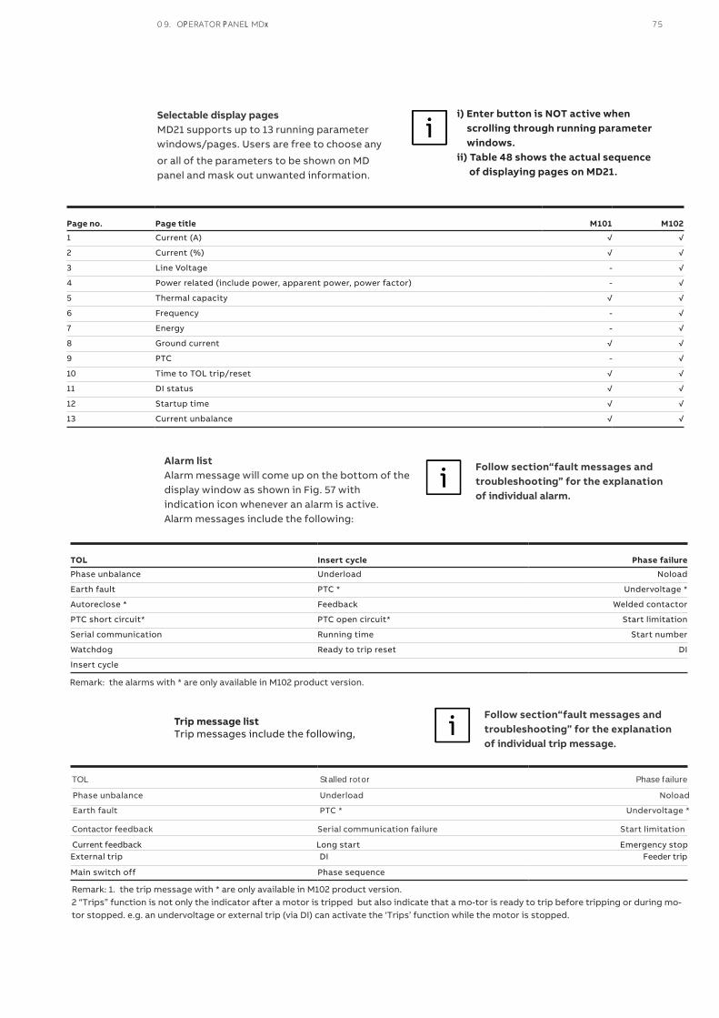
Selectable display pages MD21 supports up to 13 running parameter windows/pages. Users are free to choose any
or all of the parameters to be shown on MD panel and mask out unwanted information.
Page no. Page title M101 M102
1 Current (A) √ √
2 Current (%) √ √
3 Line Voltage - √
4 Power related (include power, apparent power, power factor) - √
5 Thermal capacity √ √
6 Frequency - √
7 Energy - √
8 Ground current √ √
9 PTC - √
10 Time to TOL trip/reset √ √
11 DI status √ √
12 Startup time √ √
13 Current unbalance √ √
i) Enter button is NOT active when scrolling through running parameter windows.ii) Table 48 shows the actual sequence of displaying pages on MD21.
Follow section“fault messages and troubleshooting” for the explanation of individual alarm.
Alarm listAlarm message will come up on the bottom of the display window as shown in Fig. 57 withindication icon whenever an alarm is active.Alarm messages include the following:
TOL Insert cycle Phase failure
Phase unbalance Underload Noload
Earth fault PTC * Undervoltage *
Autoreclose * Feedback Welded contactor
PTC short circuit* PTC open circuit* Start limitation
Serial communication Running time Start number
Watchdog Ready to trip reset DI
Insert cycle
Remark: the alarms with * are only available in M102 product version.
TOL Stalled rotor Phase failure
Phase unbalance Underload Noload
Earth fault PTC * Undervoltage *
Contactor feedback Serial communication failure Start limitation
Current feedback Long start Emergency stopExternal trip DI Feeder trip
Main switch off Phase sequence
Trip message listTrip messages include the following,
Follow section“fault messages and troubleshooting” for the explanation of individual trip message.
Remark: 1. the trip message with * are only available in M102 product version.2 “Trips” function is not only the indicator after a motor is tripped but also indicate that a mo-tor is ready to trip before tripping or during mo-tor stopped. e.g. an undervoltage or external trip (via DI) can activate the ‘Trips’ function while the motor is stopped.
0 9. OPERATOR PANEL MDx 75

The menu treesPress the back button at monitoring value display window to enter the main configuration menu.
Press up/down button, can move the highlight to previous/next items. Press enter button to enter next level of menu.
Press the back button at the main configura-tion menu to enter running parameter win-dow.
—58 View of main configuration menu tree
76 M OTO R CO NTRO L A N D PROTE C TI O N U N IT M10X USER G U I D E

Password protection from MD panel Password protection can be activated on MD21 panel to avoid unauthorized operations from switch-board front.
The operations which can be password protected include start, stop, trip reset, alarms. The password protection may also be activated for acknowledging trip messages only when necessary.
Only one set of password is required for all operations and parameter settings/changes. The password should be reset and managed by the end users according to individual plant management policy. The initiate password is “1111”.
1) Password protection function is related to the operations via MD21 panel only! In case operations are from hardwiring or fieldbus, they are not bonded by this feature.
Activate password protection function:
Pressing button > Select ’Operator panel’>
‘StartPwOn’ – select ‘On’ to turn on password for ‘start’ control
“StopPwOn’- select ‘On’ to turn on password for ‘stop’control
“TripAlarmPwOn’- select ‘On’ to turn on password for ‘trip reset’ and acknowledging alarm/trip mes-sages.
Operating Start/stop with password Option 1: Press start1/2/stop button, MD21 will prompt up password window. Once the correct pass-word is entered, press again ‘start1/2/stop” to initiate the operation. Fail to press ‘start1/2/stop’ but-ton within 30 seconds after entering the password will bring up password window again. Option 2: Go to the main menu and select “Operation “Select desired operation from the list.
If motor is tripped, start/stop command will be latched. That means password window will not prompt up when start/stop command is given via MD21.
Operating Trip Reset with passwordStep 1: Activate ‘TripAlarmPwOn’ on MD21.Step 2: Select trip reset mode parameter as ‘local’ or ‘local &remote’ via MD21 panel
If reset mode is set to ‘remote’, trip reset with password is not available.
Step 3: When motor trips, trip message comes up on MD21, “fault’ LED switches ON. There are two possibilities to reset the trip message:a) Press stop button, then “reset trip?” message comes up.b) Press back button to enter setting menu. Select ‘Operations’ > ‘Reset Trip’ to enter “reset trip?” window.Step 4: Press enter button at ‘reset trip?’ window.Step 5: Enter the password. If password is correct, M10x will execute trip reset command. If password is wrong, MD21 will go back to “reset trip?“ message following ‘Invalid password’ message.
If the cause of trip is removed, trip will be reset. If the cause of trip persists, ‘Remove the cause before reset’ message comes up with no further response. It goes back to trip message win-dow after 3s.
In case that ‘TripAlarmPwOn function’ is activated, password input is always needed for every trip reset function
Acknowledge Alarm message with/without passwordWhen there is an alarm, alarm message comes up on MD21, “fault’ LED flashing. The alarm message displayed is a real time message and disappear when the cause of the alarm is removed. Users may refer to SOE list for history alarms.
When an alarm or multiple alarms are present but not critical to the process, it is also possible to sup-press the alarms temporally after acknowledging the alarm with or without password protection. Once the alarm is acknowledged, a ‘*” mark is removed from the message description while the message remains on the alarms list until the cause is removed. The LED stops flashing after all the alarms are acknowledged but remains ON after acknowledgement.
0 9. OPERATOR PANEL MDx 77

78 M OTO R CO NTRO L A N D PROTE C TI O N U N IT M10X USER G U I D E
Acknowledge with passwordStep 1: Activate ‘TripAlarmPwOn’ on MD21.Step 2: Select ‘Operations’ > ‘Alarm Acknowledge’ to prompt a password window. Step 3: Enter the password. If password is correct, all active alarms are listed. If password is wrong, MD21 will go back to previous menu following ‘Invalid password’ message.
Step 4: Select the alarm to be acknowledged via up/down button, then press enter button to acknowledge the message.
Acknowledge without passwordSkip step 1 above and select ‘Alarm Acknowledge’ will display active alarms without asking for pass-word. Then carry on from Step4.
OperationWithin this submenu, start/stop can be triggered, trip can be reset, and alarm can be acknowledged. Below table shows the organization of the different parameter masks in the menu tree.
Level 1 Level 2
Operation Trip Reset
Alarm Acknowledge
Start1
Start2
Stop
—Table 48 Menu tree of operation
ParameterWithin this submenu, all motor related parameters can be configured. Table 49 shows the organization of the different parameter masks in the menu tree.
For more details about parameters, please refer to the document: M10x parameter description.

Level 1 Level 2 Level 3 Level 4 Level 5
Parameter Protection TOL2 Function
Disabled during start9
Reset mode9
Thermal mode9
TOL bypass9+10
T69+10
Cool coe.9
Te9+11
Ia/In9+11
Alarm level9
Trip level9
Reset level9
Ambient temperature9
Stall2 Function
Reset mode9
Trip level9
Trip delay9
Phase failure2 Function
Reset mode9
Alarm level9+12
Trip level9
Trip delay9
Unbalance2 Function
Reset mode9
Alarm level9+12
Trip level9
Trip delay9
Underload2 Function
Reset mode9
Alarm level9+12
Trip level9
Trip delay9
Long stop2 Function
Reset mode9
Alarm level9+12
Trip level9
Trip delay9
Earth fault Function
Enabled duration stop9+12
Reset mode9
Alarm level9+12
Trip level9
Trip delay9
—Table 49 Menu tree of parameter
0 9. OPERATOR PANEL MDx 79
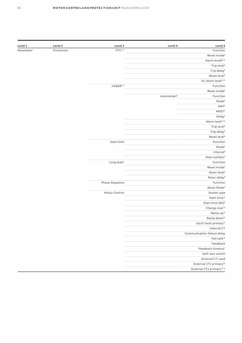
80 M OTO R CO NTRO L A N D PROTE C TI O N U N IT M10X USER G U I D E
Level 1 Level 2 Level 3 Level 4 Level 5
Parameter1 Protection PTC2+3 Function
Reset mode9
Alarm level9+12
Trip level9
Trip delay9
Reset level9
SC Alarm level9+12
UV&AR2+3 Function
Reset mode9
Autorestart9 Function
Mode9
MAT9
MPDT9
Delay9
Alarm level9+12
Trip level9
Trip delay9
Reset level9
Start limit Function
Mode9
Interval9
Start number9
Long start2 Function
Reset mode9
Rotor level9
Rotor delay9
Phase Sequence Function
Reset Mode9
Motor Control Starter type
Start time14
Start time (N2)6
Change over15
Ramp up16
Ramp down16
Earth fault primary17
Internal CT
Communication failure delay
Fail safe18
Feedback
Feedback timeout7
Soft test switch
External CT used
External CT1 primary20
External CT2 primary20+6

Level 1 Level 2 Level 3 Level 4 Level 5
Parameter1 Control Motor Control External CT secondary20
Control authority Profibus option19 Auto mode active
Soft local/ remote19 Soft local/ remote19 L hardwiring
R fieldbus
MD control19 MD control19 MD operator panel
MD in local
MD in remote
MD in auto Mode0
MD in auto Mode1
Grouping Function
Direction9
Group number9
Start delay9
Start delay9
Communication MODBUSRTU4 Address
Parity
Redundancy
Baud rate
PROFIBUSDPV15 Address
Mode
Block DP
Motor info Motor type
Voltage3
Frequency
Rated power
In
In (N2)6
DI Type
DI0 ~DI12 (24VDC) or DI0-DI8 (110V or 240VAC)
Function
Contact type
Delay21
Operation22
DO DO1 Function
Delay
Principle
DO23 Function
Delay
Principle
Maintenance Running hour Function
Alarm level9
Start number Function
Alarm Level9
Note: Items with marks will only display when they meet corresponding conditions shown below.
0 9. OPERATOR PANEL MDx 81

82 M OTO R CO NTRO L A N D PROTE C TI O N U N IT M10X USER G U I D E
1: MD21 is connected with M10x.2: Starter type is NOT set to be Feeder. 3: MD21 is connected to M102.4: MD21 is connected to M10x-M.5: MD21 is connected to M10x-P.6: Starter type is set to be NR_2N|NR_2N Dahlander.7: Feedback function set as "Enabled". 8: Backup parameter has ever been performed at least once.9: Related Function is set to be On.10: TOL Thermal mode is set to be Standard.11: TOL Thermal mode is set to be EExe.
12: Related Function is set to be Alarm only. 13: MD21 is connected to M101.14: Starter type is NOT set to be NR_softstarter|REV_softstarter.15: Starter type is set to be NR_S_ D|NR_2N| Dahlander|Autotransformer.16: Starter type is set to be NR_softstarter| REV_softstarter.17: Earth fault Function is set to be “On|Alarm only.18: “Comm. F Delay” is NOT set to be “255”.19: Details refer to Control Authority chapter. 20: Ex CT Used is set to be Yes.
Operator panelWithin this submenu, LCD display and LED indication can be configured. Table 50 shows the organization of the different parameter masks in the menu tree.
For more details about parameters, please refer to the document: M10x Parameter Description.
Level 1 Level 3 Level 2 Level 4
Operation LCD display Current (A)
Current (%)
Line voltage1
Power related1
Thermal capacity
Frequency1
Energy1
Ground current
PTC1
Time to TOL trip/reset
DI status
Startup time
Current unbalance
LED indication LED1 Function
Color
LED2 Function
Color
LED3 Function
Color
LED4 Function
Color
Language
TripAlarmPwOn
StartPwOn
StopPwOn
Password setup
—Table 50 Menu tree of operator panel
Remark: 1 available in M102 product version only.

Level 1 Level 2
Time setting Year
Month
Day
Hour
Minute
Second
Week
Level 1 Level 2
Maintenance SOE*
Running time
Start time
Start number
Start number
Trip number
Last trip current(%)
Last trip current(A)
Last trip EF current
Insertion cycle
Parameter change counter
—Table 51 Menu tree of time setting
—Table 52 Menu tree of maintenance
Time settingWithin this submenu, actual time can be configured. Table 51 shows the organization of the different parameter masks in the menu tree.
MaintenanceWithin this submenu, all motor related maintenance can be configured.
Remark: * available in M102 product version only.
Product informationWithin this submenu, information of M10x and MD21 can be read.
Level 1 Level 2
Product information Fieldbus address
Type of M10x
Firm version of M10x
Firm version of MD
—Table 53 Menu tree of product information
0 9. OPERATOR PANEL MDx 83

84 M OTO R CO NTRO L A N D PROTE C TI O N U N IT M10X USER G U I D E
Level 1 Level 2
Backup and download Backup parameter
Download backup1
—Table 54 Menu tree of backup and download
Backup and downloadThe backup feature is for reading parametersfrom the M10x device and creating a backup file in the MD panel. The download feature is for downloading backup files from MD panel to M10x device.
This feature is easy to operate onsite, and is use-ful when similar parameters are required for sev-eral M10x devices.
Backup parameter: Saves current parameter to backup register in MD21. Download backup: Downloads the parameter in backup register into M10x.
1) The download backup option is not available until the backup parameter function has been executed.2) Remember to change slave address after copying parameters from other devices to avoid communication problems.
TestSelect this submenu, M10x will conduct a self-diagnosis to health check hardware circuits, firmware programs and operation functions.
Adjusting parametersSelect the item at the last parameter level and press enter. A password window will appear. Always change the default password after first login for secure operation purpose
After changing the parameters, press the back
button to return and confirm before down-loading the new parameter..
1. Default password is 1111.2. The slave address can be
revised and downloaded to M10x via MD21.
—59 adjusting parameters

Connection portsThere are two connection ports available on MDx
panel. RJ11 port which locates on the back of the
panel connects to M10x main unit. A mini USB port
is available on the front for parameterization con-
nection.
A dedicated parameterization cable is required to
connect between MDx panel and the laptop.
If MD21 cannot read the informationfrom M10x, a "No Comm" message ap-pears. This may refer to a bad connec-tion between MD21 panel and M10x ora possible failure in M10x main unit.
—60 MD21 connection ports
—61 Connection between M10x and MDx
MDx adaptor MDx adaptor is the adaptor kit which is designed to connect M10x main unit to an external MDx control panel. MDx adaptor kit include a compact IP65 socket which is to be installed on the front
panel of the each starter and a couple of connection cables. The connection between M10x and MDx is shown in Fig61. Details of ordering, please refer to M10x ordering guide.
0 9. OPERATOR PANEL MDx 85

—10. Communication interface
OverviewM10x supports three types of communication protocol: MODBUS RTU, PROFIBUS DP and MODBUS TCP.
MODBUS RTUThe physical fieldbus interface in M10x-M is RS485. There are two identical RS485 interfaces for redundant design. All functions are sup-ported via RS485, eg, parameterization, control, supervisions, etc.
The M10x-M implements a subset of the Modicon MODBUS RTU serial communication standard. MODBUS is a single master/multiple slave type of protocol suitable for a multi-drop configuration
as provided by RS485 hardware. The M10x-M is al-ways a MODBUS slave, and cannot be programmed as a master. Commonly, computers or PLCs serve as masters.
Both monitoring and control are possible using read and write register commands. Other commands are supported to provide additional functions.
Modbus RTU networkAll devices are connected in bus structure. In one segment, up to 32 modules can be connected. At the beginning and the end of one segment, the cable is terminated with a resistor. The maximum length depends on cable type and baud rate.
Function descriptionThe following functions are supported by the M10x-M: (FC=Function code)FC02 Read settings and actual valuesFC03 Read settings and actual values FC04 Read settings and actual values FC05 Execute operationFC06 Store single settingFC08 Loop back testFC10 Store multiple settings
For more details on the M10x MODBUS, refer to M10x-M MODBUS Protocol Implementation.
86 M OTO R CO NTRO L A N D PROTE C TI O N U N IT M10X USER G U I D E
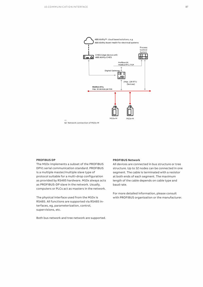
PROFIBUS DPThe M10x implements a subset of the PROFIBUS DPV1 serial communication standard. PROFIBUSis a multiple master/multiple slave type of protocol suitable for a multi-drop configurationas provided by RS485 hardware. M10x always acts as PROFIBUS-DP slave in the network. Usually, computers or PLCs act as masters in the network.
The physical interface used from the M10x is RS485. All functions are supported via RS485 in-terfaces, eg, parameterization, control, supervisions, etc.
Both bus network and tree network are supported.
—62 Network connection of M10x-M
PROFIBUS NetworkAll devices are connected in bus structure or tree structure. Up to 32 nodes can be connected in one segment. The cable is terminated with a resistorat both ends of each segment. The maximum length of the cable depends on cable type and baud rate.
For more detailed information, please consult with PROFIBUS organization or the manufacturer.
10.CO M M U N I C ATI O N I NTER FACE 87
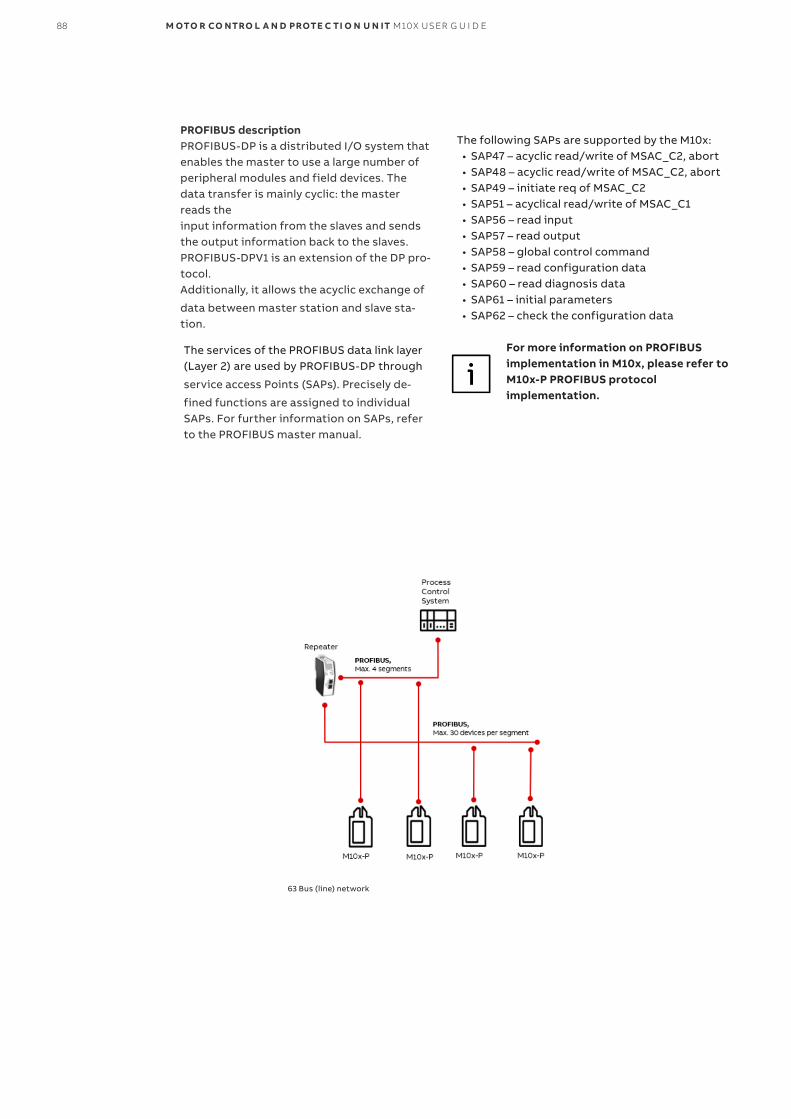
The services of the PROFIBUS data link layer (Layer 2) are used by PROFIBUS-DP through
service access Points (SAPs). Precisely de-
fined functions are assigned to individual SAPs. For further information on SAPs, refer to the PROFIBUS master manual.
The following SAPs are supported by the M10x: • SAP47 – acyclic read/write of MSAC_C2, abort • SAP48 – acyclic read/write of MSAC_C2, abort • SAP49 – initiate req of MSAC_C2 • SAP51 – acyclical read/write of MSAC_C1 • SAP56 – read input • SAP57 – read output • SAP58 – global control command • SAP59 – read configuration data • SAP60 – read diagnosis data • SAP61 – initial parameters • SAP62 – check the configuration data
For more information on PROFIBUS implementation in M10x, please refer to M10x-P PROFIBUS protocol implementation.
63 Bus (line) network
PROFIBUS descriptionPROFIBUS-DP is a distributed I/O system that enables the master to use a large number of peripheral modules and field devices. The data transfer is mainly cyclic: the master reads the input information from the slaves and sends the output information back to the slaves. PROFIBUS-DPV1 is an extension of the DP pro-tocol. Additionally, it allows the acyclic exchange of
data between master station and slave sta-tion.
88 M OTO R CO NTRO L A N D PROTE C TI O N U N IT M10X USER G U I D E
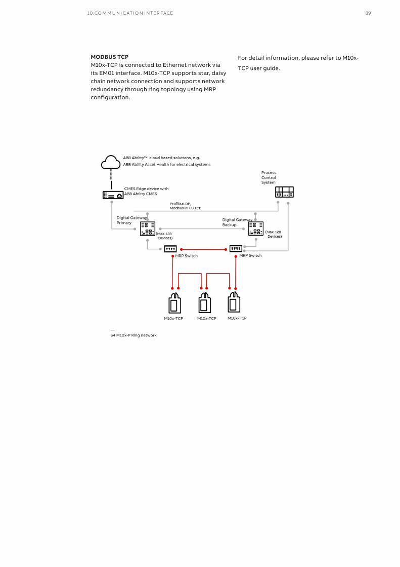
—64 M10x-P Ring network
MODBUS TCPM10x-TCP is connected to Ethernet network via its EM01 interface. M10x-TCP supports star, daisy chain network connection and supports network redundancy through ring topology using MRP configuration.
For detail information, please refer to M10x-
TCP user guide.
10.CO M M U N I C ATI O N I NTER FACE 89
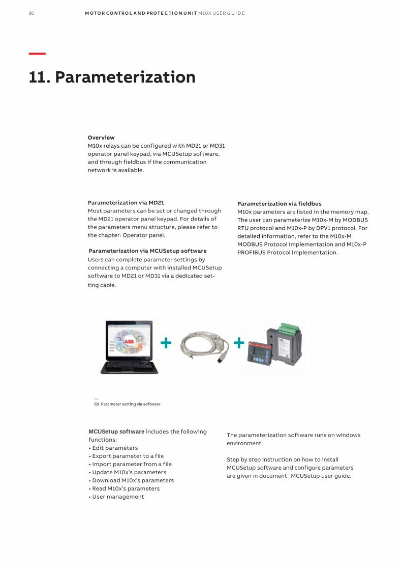
—11. Parameterization
OverviewM10x relays can be configured with MD21 or MD31 operator panel keypad, via MCUSetup software, and through fieldbus if the communication network is available.
Parameterization via MD21Most parameters can be set or changed through the MD21 operator panel keypad. For details of the parameters menu structure, please refer to the chapter: Operator panel.
Parameterization via MCUSetup softwareUsers can complete parameter settings by connecting a computer with installed MCUSetupsoftware to MD21 or MD31 via a dedicated set-
ting cable.
Parameterization via fieldbusM10x parameters are listed in the memory map. The user can parameterize M10x-M by MODBUS RTU protocol and M10x-P by DPV1 protocol. For detailed information, refer to the M10x-M MODBUS Protocol Implementation and M10x-P PROFIBUS Protocol Implementation.
MCUSetup software includes the following functions:• Edit parameters• Export parameter to a file• Import parameter from a file• Update M10x’s parameters• Download M10x’s parameters• Read M10x’s parameters• User management
The parameterization software runs on windows environment. Step by step instruction on how to install MCUSetup software and configure parameters are given in document ' MCUSetup user guide.
—65 Parameter setting via software
90 M OTO R CO NTRO L A N D PROTE C TI O N U N IT M10X USER G U I D E

—12. Fault Messages and Troubleshoot
Self-diagnosis featureM10x has built in self-diagnosis program to actively health check the internal hardware circuits and software programs. The ‘test’ function through MD21 panel can also activate the health checking pro-gram on request.
• WatchdogA hardware watchdog is designed to supervisethe health checking program. In case anyhardware or software failure is detected by the program, a reset is triggered from the watchdog to restart the program. In the meantime, a watch-dog alarm message is generated.
A watchdog alarm is a warning of one time health check failure. The cause of the failure may be tem-porary due to external disturbance/EMC environ-ment and may not necessarily be severe. However once a watchdog alarm message occurs,
it is necessary to be closely monitored. If the watchdog alarm is trigger frequently, a follow-up service and maintenance shall be scheduled shortly..
In case of severe hardware or firmware failure, the relay will no longer be resettable and required to be replaced immediately.
The watchdog can be configured to one of the digital output relays and monitored through hardwiring.
• TestSelecting TEST option under the main menu of MD21 panel activates a comprehensive health checking of M10x and MD21 including hardware circuits, firmware programs and operation functions.
Fault messages and trouble shoots
Condition Description Possible Cause Suggested Action
Thermal Capacity Alarm Motor is about to be stopped.the motor thermal level reaches thermal capacity level alarm level
The motor is under thermal overload condition. Unacceptable heating-up of motor winding.
Check the process conditions:> If itis extreme starting conditions, high overload or intermittent operation; Check the motor condition:> Cooling problem, ambient temperature too high; mechanical problem;Check the thermal model relevant parameters: the Ie setting, T6 time and ambient temperature setting, the thermal level setting etc.
Overload Alarm Motor is about to be stopped.The motor is in overload condition, i.e. measured current ILmax > 1.14 x TFLC (thermal full load current multiplier reduced by motor ambient temperature)
The motor is in overload condition Check the process conditions; Check motor load; Check parameter settings.
Phase Failure Alarm Motor is about to be stopped.The maximum imblance current of any phase reaches the phase failure alarm level.
Phase failure in motor phase currents generally occurs because of pitted contacts in the contactor or SCPD, imbalance in the mains supply, loose connections, blown fuse, and faults within the motor.
Check for blown fuseCheck for pitted contacts in contactor or SCPD Check for loose connection on power supply Check the motor connection
1 2 . FAU LT M E SS AG E S A N D TR O U B L ESH O OT 91
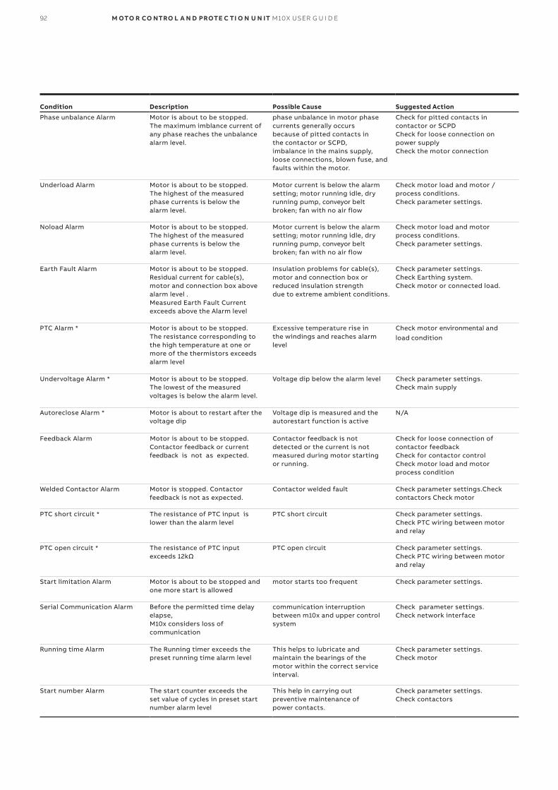
Condition Description Possible Cause Suggested Action
Phase unbalance Alarm Motor is about to be stopped.The maximum imblance current of any phase reaches the unbalance alarm level.
phase unbalance in motor phase currents generally occurs because of pitted contacts in the contactor or SCPD, imbalance in the mains supply, loose connections, blown fuse, and faults within the motor.
Check for pitted contacts in contactor or SCPD Check for loose connection on power supply Check the motor connection
Underload Alarm Motor is about to be stopped.The highest of the measured phase currents is below the alarm level.
Motor current is below the alarm setting; motor running idle, dry running pump, conveyor belt broken; fan with no air flow
Check motor load and motor / process conditions.Check parameter settings.
Noload Alarm Motor is about to be stopped. The highest of the measured phase currents is below the alarm level.
Motor current is below the alarm setting; motor running idle, dry running pump, conveyor belt broken; fan with no air flow
Check motor load and motor process conditions.Check parameter settings.
Earth Fault Alarm Motor is about to be stopped.Residual current for cable(s), motor and connection box above alarm level .Measured Earth Fault Current exceeds above the Alarm level
Insulation problems for cable(s), motor and connection box or reduced insulation strength due to extreme ambient conditions.
Check parameter settings.Check Earthing system.Check motor or connected load.
PTC Alarm * Motor is about to be stopped.The resistance corresponding to the high temperature at one or more of the thermistors exceeds alarm level
Excessive temperature rise in the windings and reaches alarm level
Check motor environmental and load condition
Undervoltage Alarm * Motor is about to be stopped.The lowest of the measured voltages is below the alarm level.
Voltage dip below the alarm level Check parameter settings.Check main supply
Autoreclose Alarm * Motor is about to restart after the voltage dip
Voltage dip is measured and the autorestart function is active
N/A
Feedback Alarm Motor is about to be stopped. Contactor feedback or current feedback is not as expected.
Contactor feedback is not detected or the current is not measured during motor starting or running.
Check for loose connection of contactor feedback Check for contactor controlCheck motor load and motor process condition
Welded Contactor Alarm Motor is stopped. Contactor feedback is not as expected.
Contactor welded fault Check parameter settings.Check contactors Check motor
PTC short circuit * The resistance of PTC input is lower than the alarm level
PTC short circuit Check parameter settings.Check PTC wiring between motor and relay
PTC open circuit * The resistance of PTC input exceeds 12kΩ
PTC open circuit Check parameter settings.Check PTC wiring between motor and relay
Start limitation Alarm Motor is about to be stopped and one more start is allowed
motor starts too frequent Check parameter settings.
Serial Communication Alarm Before the permitted time delay elapse, M10x considers loss of communication
communication interruption between m10x and upper control system
Check parameter settings.Check network interface
Running time Alarm The Running timer exceeds the preset running time alarm level
This helps to lubricate and maintain the bearings of the motor within the correct service interval.
Check parameter settings.Check motor
Start number Alarm The start counter exceeds the set value of cycles in preset start number alarm level
This help in carrying out preventive maintenance of power contacts.
Check parameter settings.Check contactors
92 M OTO R CO NTRO L A N D PROTE C TI O N U N IT M10X USER G U I D E

Condition Description Possible Cause Suggested Action
DIx Alarm Motor is about to stop if the DIx changes status from healthy to unhealthy during running ; Motor is prevented from starting if the DIx input is unhealthy.
The process interlock1 switch remain inactive on the occurrence of a motor start or the process interlock2 switch remain active when motor is in running.
Check DI settings on process interlock. Check DIx wirings
Watchdog Alarm Internal hardware watchdog activated
Hardware fault or internal pro-gram running fault (if it is a tem-porary fault, it is recoverable after power cycling ).
Check if it is recoverable (by cycling the power)Change hardware if it is not recoverable
No Comm The communication between MDx display and M10x main unit is interrupted or M10x simply stops functioning.
Physical connection is damaged between MDx display and M10x. M10x is no longer in working mode.
Check if the cable connection is in good condition; Check if MDx or M10x relay is in working condition (by swapping with spares)
TOL Trip Motor is stopped.The motor thermal level reaches thermal capacity trip level
The motor is under thermal overload condition. Unacceptable heating-up of motor windings.
Check the process conditions:>If it is extreme startingconditions, high overloador intermittent operation.Check the motor condition:> Cooling problem, ambient temperaturetoo high; mechanical problem;Check the thermal model relevant parameters:> Check the Ie setting,T6 time and ambient temperature setting, the thermal level settingetc.
Stalled rotor Trip Motor is stopped.The highest of the measured phase currents remains above the trip level for a trip delay time
The driven mechanical system from jams and excessive overloads
Check parameter settings.Check motor connected load and process condition.
Phase Failure Trip Motor is stopped.the ratio between the lowest phase current to the highest phase current (ILMIN / ILMAX) from the measured currents of all three phases is below the trip level
Phase failure in motor phase currents generally occurs because of pitted contacts in the contactor or SCPD, imbalance in the mains supply, loose connections, blown fuse, and faults within the motor.
Check for blown fuseCheck for pitted contacts in contactor or SCPD Check for loose connection on power supply Check the motor connection
Phase unbalance Trip Motor is stopped.the ratio between the lowest phase current to the highest phase current (ILMIN / ILMAX) from the measured currents of all three phases is below the trip level.
Phase failure in motor phase currents generally occurs because of pitted contacts in the contactor or SCPD, imbalance in the mains supply, loose connections, blown fuse, and faults within the motor.
Check for blown fuseCheck for pitted contacts in contactor or SCPD Check for loose connection on power supply Check the motor connection
Underload Trip Motor is stopped.The highest of the measured phase currents is below the trip level.
Motor current is below the alarm setting; motor running idle, dry running pump, conveyor belt bro-ken; fan with no air flow
Check motor load and motor / process conditions.Check parameter settings.
Noload Trip Motor is stopped. The highest of the measured phase currents is below the trip level.
Motor current is below the alarm setting; motor running idle, dry running pump, conveyor belt broken; fan with no air flow
Check motor load and motor process conditions.Check parameter settings.
Earth fault Trip Motor is stopped. Residual current for cable(s), motor and connection box above trip level.
Insulation problems for cable(s), motor and connection box or reduced insulation strength due to extreme ambient conditions. Consider whether starpoint of IT-networks may have moved.
Check parameter settings.Check Earthing system.Check motor or connected load.
PTC Trip * Motor is stopped.The resistance corresponding to the high temperature at one or more of the thermistors exceeds trip level
Excessive temperature rise in the windings
Check parameter settings.Check PTC inputCheck motor
1 2 . FAU LT M E SS AG E S A N D TR O U B L ESH O OT 93

Condition Description Possible Cause Suggested Action
Undervoltage Trip * Motor is about to be stopped.The lowest of the measured voltages is below the trip level.
Voltage dip below the trip level Check parameter settings.Check main line voltage
Contactor Feedback Trip Motor is stopped. Contactor feedback is not as expected.
Contactor feedback fault Check for loose connection of contactor feedback Check for contactor controlCheck motor load and motor process condition
Serial Communication Trip After the permitted time delay elapse, M10x considers loss of communication and activates failsafe
communication interruption between m10x and upper control system
Check parameter settings.(change the setting to "255" will disable the communication supervision);Check network interface
Start limitation Trip Motor is stopped and a new start is prevented.
The motor starts too frequent and the number of starts in a given interval is reached start limitation
Check parameter settings.
DIx Trip Motor is tripped because the DIx changes status from healthy to unhealthy during running ; Motor is prevented from starting because the DIx input is unhealthy.
The process interlock1 switch remain inactive on the occurrence of a motor start or the process interlock2 switch remain active when motor is in running.
Check DI settings on process interlock. Check DIx wirings
Long start Trip Motor is stopped. After a start signal, when the measured phase currents remain above the set value for a locked rotor delay time during the startup time
motor locked or stalled in start state and signals a fault when current continuously exceeds a separately set threshold after a start command for the same period of time.
Check parameter settings.Check motor or connected load.
Feeder trip Motor is stopped because of external trip input of feeder starter type.
The input is defined as ‘external trip’, M10x will trip the motor after a high input is detected.
Check parameter settings.Check Digital input wiring.
Emergency stop trip Motor is stopped because of emergency stop input.
The input is defined as ‘emergency stop’, M102 will stop or trip the motor after a high input is detected.
Check parameter settings.Check Digital input wiring.
External Trip Motor is stopped because of external trip input.
The input is defined as ‘external trip’, M10x will trip the motor after a high input is detected.
heck parameter settings. Check Digital input wiring.
Main switch off trip Motor is stopped because of main switch input.
The input is defined as ‘Main switch status’, M10x will trip the motor after a low input is detected.
Check parameter settings.Check Digital input wiring.
Current feedback trip Motor is stopped. Current feedback is not as expected.
Current is not measured during motor starting or running. Or current is measured while starter is detected in test position.
Check parameter settings if 'soft test' is enabled. Check motor connected load and process condition.
94 M OTO R CO NTRO L A N D PROTE C TI O N U N IT M10X USER G U I D E

—13. Appendix A: Technical data
Main circuit
Rated operation voltage (Ue) up to 400/690VAC
Rated insulation voltage (Ui) 690VAC
Rated impulse withstand voltage (Uimp) 6KV, overvoltage category II in IT network, Category III in other networks.
Degree of pollution 3
Rated operation current (Ie) 0.24-63A
Rated frequency 50/60Hz
Control circuit
Rated operational voltage (Ue) 24V DC ,110 or 240 VAC
Rated insulation voltage (Ui) -250VAC
Rate impulse withstand voltage 4kV for AC circuit
Rated operational current (Ie)
Contactor control relay output (CCA,CCB,CCC)Digital output
2A /24VDC(DC-13)
4A/120VAC(AC-15)
2A/240VAC(AC-15)
Rated frequency 50/60 Hz
Response timing accuracy
TOL protection 5% of tolerance of tripping time
Stall protection 200 ~ 350ms
Earth fault protection -30~+30ms
PTC protection 400 ~ 500ms
Others 0 ~ 150ms
Power supply
Rated operational voltage (Ue) 24VDC , 110 or 240VAC
Voltage operation range 85%-110% Ue
Power consumption
24VDC 110VAC 240VAC
Typical 5W 6VA 12VA
Maximum 8W
Maximum inrush current * 600ma
Digital input (DC)
Number of digital inputs 13 with one common connection
Logic 1 15…30V
Logic 0 0…5V
Digital input (AC)
Number of digital inputs 9 with one common connection
Logic 1 110VAC type, 79…110V 240VAC type, 164…240V
Logic 0 110VAC type, 0…20V 240VAC type, 0…40V
—Technical data
1 3 . A PPEN D I X A : TECH N I C A L DATA 95

Fieldbus interface
Protocol PROFIBUS-DP/MODBUS RTU
Baud rate PROFIBUS DP9.6kbps/19.2kbps/45.45kbps/93.75Kbps/187.5Kbps/500Kbps/1.5MbpsMODBUS RTU 1200/4800/9600/19200/38400/57600 bps
Fieldbus capacity 32 nodes per segment
Degree of protection
M10x IP20
MD21/MD31 IP54 from module front
Environmental conditions
Storage -40 ~ +85°C
Normal operation 24VDC type -10 ~ +60°C
110/240VAC type Vertical mounting: -10 ~ +60°C Horizontal mounting: -10 ~ +55°C
Humidity 15% up to 95% without dew
Derating accepted operating altitude 4500m
Without derating operating altitude 2000m
EMC environment Equipment in the system complies with EMC requirement of CE/CCC certificate.Power supply system complies with IEC61000-2-1, IEC61000-2-2, especially the system in which VSD/frequency converters are used.
Metering accuracy
Phase current Range: 0.4-8 × phase CT primary amps Accuracy: ±2% or ±0.01A, whichever is greater
Earth fault current Full scale: 1.2 × RCT nominal current Accuracy: ±2% RCT primary
Line voltage (M102 only) Voltage measurement range: 100V - 690V Accuracy: ±2%
Power (only for M102) Accuracy: ±5% or ±0.1kW, whichever is greater
Thermistor input (only for M102) Sensor type: positive temperature coefficient PTC RHOT=100-10,000 ΩAccuracy: ±2% or 10Ω which is greater
Installation
Mounting MCU On TS35 DIN rail
With 3 screws ST4.2 (tightening torque 4.5Nm)
With 2 screws (tightening torque 0.1Nm)
Mounting position (MCU) Vertical (DIN and screw)
Horizontal (screw only)
Dimension MCU 110mm X 140mm X 75mm
MD21 91mm X 75mm X 24.3mm
MD31 88mm X 50mm X 24.3mm
Wiring size Terminal X1 DC type 1.5mm2
AC type 2.5mm2
Terminal X3 2.5mm2
Terminal X4 2.5mm2
Tightening torque
96 M OTO R CO NTRO L A N D PROTE C TI O N U N IT M10X USER G U I D E
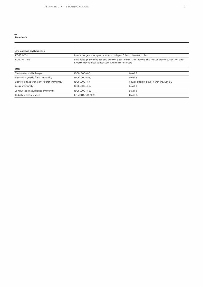
Low voltage switchgears
IEC60947-1 Low voltage switchgear and control gear” Part1: General rules
IEC60947-4-1 Low voltage switchgear and control gear” Part4: Contactors and motor starters, Section one-Electromechanical contactors and motor starters
EMC
Electrostatic discharge IEC61000-4-2, Level 3
Electromagnetic field immunity IEC61000-4-3, Level 3
Electrical fast transient/burst immunity IEC61000-4-4 Power supply, Level 4 Others, Level 3
Surge immunity IEC61000-4-5, Level 3
Conducted disturbance immunity IEC61000-4-6, Level 3
Radiated disturbance EN55011/CISPR 11, Class A
—Standards
1 3 . A PPEN D I X A : TECH N I C A L DATA 97

All rights reserved. Specifications subject to change without notice. 1T
NC
9111
12D
020
9 0
5.20
21
Additional informationWe reserve the right to make technicalchanges or modify the contents of thisdocument without prior notice. Withregard to purchase orders, the agreedparticulars shall prevail. ABB AG doesnot accept any responsibilitywhatsoever for potential errors orpossible lack of information in thisdocument.The information in this document is subject to change without notice and should not be construed as a commitment by ABB. ABB assumes no responsi-bility for any errors that may appear in this docu-ment.In no event shall ABB be liable for direct, indirect, spe-cial, incidental, or consequential damages of any na-ture or kind arising from the use of this document, nor shall ABB be liable for incidental or consequential damages arising from use of any software or hard-ware described in this document.This document and parts thereof must not be repro-duced or copied without ABB's written permission, and the contents thereof must not be imparted to a third party nor be used for any unauthorized pur-pose. The software described in this document is fur-nished under a license and may be used, copied, or disclosed only in accordance with the terms of such license.All rights reserved.Copyright © 2021 ABB .
—ABB Ltd.Distribution SolutionsElectrification business
P.O. Box 8131
CH-8050 Zurich, Switzerland
new.abb.com/low voltage/ products/switchgear
Contact us through your local ABB contact center
new.abb.com/contact-centers


