MANUAL OF AIR TRAFFIC SERVICES Version 2.3 - 22/03/2021 WARNING Information contained in this document is intended for flight simulation purposes and must not be used for any real-world aviation use.
Transcript
MANUAL OF AIR TRAFFIC
SERVICES
Version 2.3 - 22/03/2021
WARNING
Information contained in this document is intended for flight simulation purposes and must not be used
for any real-world aviation use.
VATSIM Australia Pacific Manual of Air Traffic Services
Version 2.3: 22/03/2021 UNCONTROLLED WHEN PRINTED P 2/231
Table of Contents
Document Control .................................................................................................... 8
Change Process ....................................................................................................... 8
4.4.2 Callsigns for Air Force aircraft – single ............................................... 175
4.4.3 Callsigns for Air Force aircraft – formation .......................................... 178
4.4.4 Callsigns for Navy aircraft ................................................................... 183
4.4.5 Callsigns for Army aircraft ................................................................... 184
4.4.6 Callsigns for Special Task Operations ................................................ 186
4.4.7 Other Recognized Designators ........................................................... 187
4.4.8 Unit Callsigns ...................................................................................... 187
4.5 Other Communications ............................................................................. 187
5 Terms, Abbreviations, Definitions and Codes ............................................ 188
5.1 Terms and Definitions ............................................................................... 188
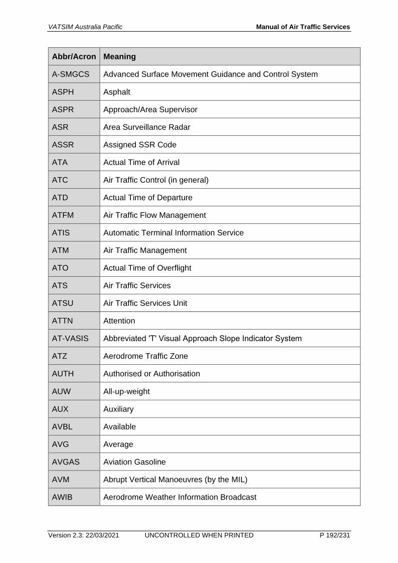
5.2 Abbreviations and Acronyms..................................................................... 188
5.3 Units of Measurement and Time ............................................................... 229
VATSIM Australia Pacific Manual of Air Traffic Services
Version 2.3: 22/03/2021 UNCONTROLLED WHEN PRINTED P 7/231
5.3.1 Units of Measurement......................................................................... 229
5.3.2 Time System ....................................................................................... 230
VATSIM Australia Pacific Manual of Air Traffic Services
Version 2.3: 22/03/2021 UNCONTROLLED WHEN PRINTED P 8/231
Document Control
Manual of Air Traffic Services Version 2.3 – 22/03/2021
Date Version Description
05/03/2015 1.0 Initial document release.
28/05/2015 2.0 Various additions to Procedural Tower training and call signs.
28/07/2017 2.2 Updated document design.
22/03/2021 2.3 Update to Parallel Approaches in IMC
Change Process
Changes to this document are made with approval from the Director Operations and after consulting the Director ATC Training.
Scope
This manual is the authoritative source of information for the general procedures for providing air traffic services within VATPAC-administered airspace. MATS covers the following flight information regions:
• Melbourne (YMMM)
• Brisbane (YBBB)
• Port Moresby (AYPM)
• Nauru (ANAU)
• Honiara (AGGG)
• Nadi (NFFF)
• Tahiti (NTTT)
VATSIM Australia Pacific Manual of Air Traffic Services
Version 2.3: 22/03/2021 UNCONTROLLED WHEN PRINTED P 9/231
Definitions
Abbreviation Definition
- -
Due to the volume of definitions, they are located at the end of this document.
Referenced Documents
Title Location
Controller Information and ATIS Policy www.vatpac.org
Code of Conduct (VATSIM) www.vatsim.net
Annex 2: Rules of the Air (ICAO) www.icao.org
Annex 11: Air Traffic Services (ICAO) www.icao.org
Procedures for Air Navigation – Air Traffic Management (ICAO)
VATSIM Australia Pacific Manual of Air Traffic Services
Version 2.3: 22/03/2021 UNCONTROLLED WHEN PRINTED P 10/231
1 Providing Air Traffic Services
1.1 Air Traffic Services
1.1.1 Objectives of Air Traffic Services
1.1.1.1 The objectives of air traffic services are to:
a) prevent collisions between aircraft;
b) expedite and maintain an orderly flow of traffic;
c) provide advice and information useful for the conduct of flights; and
d) encourage growth of a friendly and educational atmosphere between other VATSIM members.
1.1.2 Services Provided
1.1.2.1 Air traffic services shall be comprised of three distinct services:
a) The air traffic control service to satisfy 1.1.1.1 a., b., and c., divided into three parts as follows:
i. Area control services, for the provision of air traffic control service for controlled flights, except those in 1.1.2.1 a. i. and ii.;
ii. Approach control services, for the provision of air traffic control services for those parts of controlled flights associated with arrival or departure;
iii. Aerodrome control services, for the provision of air traffic control services for aerodrome traffic, except for those parts of flights described in 1.1.2.1 a. ii.;
b) The flight information service to satisfy 1.1.1.1 c.;
c) Any other services that air traffic service personnel are able to provide to satisfy 1.1.1.1. d.
1.1.2.2 A control tower may provide approach services provided that:
a) a separate approach control service is not provisioned; and
b) such services are provided without using ATS surveillance system procedures.
1.1.2.3 In order to provide control services, air traffic controllers shall:
a) be provided with information on the intended and actual movements of aircraft;
b) determine from the provided information the positions of aircraft relative to each other;
c) issue clearances as needed to ensure adequate separation between aircraft and to maintain an orderly flow of air traffic;
VATSIM Australia Pacific Manual of Air Traffic Services
Version 2.3: 22/03/2021 UNCONTROLLED WHEN PRINTED P 11/231
d) coordinate clearances with other controllers and units such that potential conflicts with aircraft under their control can be identified;
e) utilize voice and text communication such that instructions and information can be passed rapidly and efficiently.
1.1.3 Competency of Air Traffic Services Personnel
1.1.3.1 Personnel must hold the ratings and endorsements listed in the following table when providing Air Traffic Services:
Type of position ATC Rating Required endorsements
Aerodrome Control (including TWR, SMC, ACD)
S2
Procedural Tower S2 Procedural Tower Endorsement
Approach (Surveillance) S3
En route (Procedural) (except oceanic positions)
C1
En route (Surveillance) C1
Oceanic positions C1 Oceanic Endorsement
1.1.3.2 Despite the table above, a controller holding an S3 rating or higher is not required to hold a Procedural Tower Endorsement when providing an Procedural Tower service. However, the training resources provided by the endorsement are highly beneficial to providing an accurate and efficient service.
1.1.4 Traffic Priority
1.1.4.1 Apply the following priorities:
a) a landing aircraft, in the normal course of operation, has priority for the use of the landing area over a departing aircraft if the departing aircraft cannot take‐off with the prescribed separation standard;
b) landing and taking‐off aircraft have priority for the use of the landing area over taxiing aircraft;
c) an aircraft which is first able to use the manoeuvring area or desired airspace in the normal course of operation has priority.
1.1.4.2 The following list are exceptions to the ‘first come, first served’ policy:
a) RVSM-approved aircraft have priority for level requests, within the RVSM-level band, over aircraft not RVSM-approved;
b) identified aircraft have priority over non-identified aircraft;
c) aircraft with navigational approvals permitting lower separation minima have priority over aircraft requiring higher separation minima;
VATSIM Australia Pacific Manual of Air Traffic Services
Version 2.3: 22/03/2021 UNCONTROLLED WHEN PRINTED P 12/231
d) flights desiring to operate in other than normal patterns for operational rather than training reasons:
i. for a single flight, apply the same priority as other flights;
ii. when more than one aircraft requires to operate in other than a normal pattern, you may adjust priorities to consolidate and process them as a group; or
iii. defer approval to operate if it involves a short notice change to a clearance already issued to another aircraft;
e) for training aircraft:
i. flights operating in the regular traffic pattern have priority over flights desiring to operate in conflicting patterns for training purposes;
ii. when a training instrument approach is authorized, that aircraft has priority from the time that final approach in commenced until the approach is completed.
VATSIM Australia Pacific Manual of Air Traffic Services
Version 2.3: 22/03/2021 UNCONTROLLED WHEN PRINTED P 13/231
1.2 Airspace Administration
1.2.1 Airspace Classes, Services Provided and Flight Requirements
1.2.1.1 The following airspace classes are established within VATPAC airspace:
Class Flt Rules
Separation Provided
Traffic Information
Service Speed Limit
Radio Req Clc
A IFR All aircraft N/A ATC N/A
Continuous two-way
Yes
VFR not permitted
C
IFR
IFR from IFR
IFR from VFR
IFR from SVFR
N/A
ATC
250 KT below 10 000 FT except when varied by ERSA, DAP or ATC Continuous
two-way Yes
VFR VFR from IFR VFR from VFR
250 KT below 10 000 FT SVFR
SVFR from SVFR, when VIS is less than VMC
ATC
D
IFR
IFR from IFR
IFR from SVFR
IFR from VFR
ATC
250 KT below 10 000 FT
200 KT below 2500 FT AAL within 4 NM of the primary Class D aerodrome
Continuous two-way
Yes VFR None All aircraft
SVFR
SVFR from SVFR, when VIS is less than VMC
N/A
E
IFR IFR from IFR IFR from known VFR
ATC 250 KT below 10 000 FT
Continuous two-way
Yes
VFR None SIS, on request
FIS VHF carriage required
No
G IFR None IFR from known aircraft
FIS Continuous two-way
No
VATSIM Australia Pacific Manual of Air Traffic Services
Version 2.3: 22/03/2021 UNCONTROLLED WHEN PRINTED P 14/231
North of 65° S within Aus FIRs
VFR None SIS, on request
FIS O/R 250 KT below 10 000 FT
VHF carriage required above 5000 FT
G
South of 65° S within Aus FIRs
Other FIRs
IFR
None None FIS O/R 250 KT below 10 000 FT
None No VFR
Note: “O/R” means “on request”
1.2.1.2 In Class D airspace, you may approve a pilot’s request to exceed the 200 KT speed limit to a maximum of 250 KT.
1.2.1.3 You may approve speeds in excess of the limits specified for Class C airspace for air traffic management or at pilot request.
1.2.1.4 Do not clear civil aircraft in Class E airspace to operate at speeds greater than those indicated other than for safety reasons.
Note: A pilot may exceed the indicated speed limits if required due to aircraft performance.
1.2.1.5 Where airspaces adjoin vertically or laterally, apply the services provided in the airspace of lower categorisation at the common boundary.
1.2.1.6 You may exempt VFR AWK aircraft operating below 300 FT in Class C and D airspace from the requirement to maintain continuous two-way radio communication.
1.2.1.7 In Military Restricted Areas, provide services equivalent to that of Class C airspace.
1.2.2 Prohibited, Restricted and Danger Areas
1.2.2.1 Restricted Areas associated with Military ATC are active whenever that ATC is activated.
1.2.2.2 Restricted Areas associated with military flying training are only activated by VATPAC NOTAM.
1.2.2.3 Do not issue a clearance into a Prohibited or Restricted Area, except for an active Restricted Area associated with Military ATC or military flying training. Instead, issue a Safety Alert to the pilot and request that the pilot advise intentions.
VATSIM Australia Pacific Manual of Air Traffic Services
Version 2.3: 22/03/2021 UNCONTROLLED WHEN PRINTED P 15/231
1.2.3 Restricted Area Design
1.2.3.1 The purpose of this subsection is to provide guidance to military operators when requesting the activation of military flying training Restricted Areas. Use the methodology of this subsection to determine the vertical and lateral dimensions of Restricted Areas when planning military flying training operations.
1.2.3.2 The Planned Altitude/Level refers to the altitudes or levels at which the planned activity will occur.
1.2.3.3 Do not use the Planned Altitude/Level as the final levels in the calculation of airspace limits.
1.2.3.4 To calculate the Restricted Area Upper Limit (RAUL) for flying activities:
a) add a Standard Flying Activity Buffer (SFAB) of:
i. 500 FT, below FL290; or
ii. 1000 FT, at or above FL290
to the highest Planned Altitude/Level; and
b) add an Instrument/Pilot Tolerance (I/PT) buffer of:
i. 500 FT, below FL290; or
ii. 1000 FT, at or above FL290.
1.2.3.5 To calculate the Restricted Area Lower Limit (RALL) for flying activities:
a) subtract a Standard Flying Activity Buffer (SFAB) of:
i. 500 FT, below FL290; or
ii. 1000 FT, at or above FL290
to the lowest Planned Altitude/Level; and
b) subtract an Instrument/Pilot Tolerance (I/PT) buffer of:
i. 500 FT, below FL290; or
ii. 1000 FT, at or above FL290.
1.2.3.6 To calculate useable levels (for non-participating aircraft):
a) round the RAUL to the nearest 500 FT for the Lowest Usable Level (LUL); and
b) round the RALL down to the nearest 500 FT for the Highest Useable Level (HUL).
VATSIM Australia Pacific Manual of Air Traffic Services
Version 2.3: 22/03/2021 UNCONTROLLED WHEN PRINTED P 16/231
1.2.3.7 The lateral limits of the Restricted Area must encompass all activities that may occur.
1.3 Flight Data Records
1.3.1 Supported ATC Clients
1.3.1.1 VATPAC supports the following ATC clients:
a) VRC in TAAATS mode and colour profile; and
b) EuroScope with TAAATSMod.
1.3.2 Electronic Records
1.3.2.1 Record all information relating to an aircraft into the aircraft track label or electronic flight progress strip.
1.3.2.2 Record information into standard fields (such as CFL) in preference to the scratchpad field.
VATSIM Australia Pacific Manual of Air Traffic Services
Version 2.3: 22/03/2021 UNCONTROLLED WHEN PRINTED P 17/231
Recording an unrestricted descent
1.3.2.3 In this subsection, when using VRC, in lieu of “VSA” or “000”, set the CFL to 100 FT (“001”).
1.3.2.4 Set the CFL to “VSA” when an aircraft has been cleared for a visual approach.
1.3.2.5 Set the CFL to “000” when:
a) an aircraft has been cleared for an instrument approach; or
b) an aircraft has been cleared to leave a control area for unrestricted descent;
c) a pilot advises of unrestricted descent in Class G airspace.
Note: Do not select “000” for a change of cruising level in Class G airspace.
CFL reminder (TAAATSmod only)
1.3.2.6 The CFL reminder turns white when:
a) the aircraft jurisdiction is accepted;
b) the CFL is modified; or
c) the CFL is manually toggled.
1.3.2.7 Manually set the CFL to white when a transferring controller provides estimate or departure coordination or provides a level confirmation.
1.3.2.8 Reset the CFL to the normal colour when the pilot confirms or reads back the CFL.
1.3.2.9 If the CFL has been set to “VSA” or “000”, do not reset the CFL colour upon readback of the relevant clearance.
1.3.2.10 If the CFL has been set to “VSA” or “000”, reset the CFL to the normal colour upon transfer of communications to the next unit or when the pilot advises that they will no longer receive traffic information on the unit frequency.
Recording a SID or STAR clearance
1.3.2.11 When an aircraft is cleared for a SID or STAR, record this in the route field of the flight plan in the format {name}{transition}/{runway}.
Example: For the DEENA4 departure with Katoomba transition from Runway 16R, write “DEENA4KAT/16R”.
Note 1: Use the correct identifier. For example, use “SY6” instead of “SYDNEY6” or “SYD6”.
Note 2: Neglect the {transition} field for radar transitions.
1.3.2.12 Modify the route field such that the SID or STAR properly connects to the unchanged part of the route.
Example: For the route DCT ML H129 DOSEL Y59 TESAT DCT:
VATSIM Australia Pacific Manual of Air Traffic Services
Version 2.3: 22/03/2021 UNCONTROLLED WHEN PRINTED P 18/231
a) after insertion of the SID, it should read: DOSEL8/27 DOSEL Y59 TESAT DCT
b) after insertion of the STAR, it should read: DOSEL8/27 DOSEL Y59 RIVET RIVET8/16R
Recording a runway assignment without a SID or STAR
1.3.2.13 When no SID or STAR is assigned, record a runway assignment in the route field of the flight plan in the format {aerodrome}/{runway}.
Example: For a departure from or arrival to Runway 17 at Essendon, write “YMEN/17”.
Note: Apart from the insertion of the runway assignment either at the beginning (in the case of a departure) or end (in the case of an arrival), do not modify the route field, unless other modifications are required.
Use of the coordination prompt (TAAATSmod only)
1.3.2.14 Upon completion of all necessary coordination, select the coordination prompt.
1.3.2.15 If no coordination is required for an aircraft, you may select the coordination prompt immediately.
1.3.2.16 When it becomes apparent that further coordination may be necessary, unselect the coordination prompt.
1.3.2.17 Once transfer of communications to the next unit has been completed, unselect the coordination prompt.
1.3.2.18 Do not use the coordination prompt for aircraft that will be landing in your airspace.
Block level clearances (TAAATSmod only)
1.3.2.19 Use the block level clearance function rather than an annotation in the label.
1.3.2.20 For a “not above” clearance, set the lower cleared level to “000”.
1.3.2.21 For a “not below” clearance, set the upper cleared level to “600”.
Management of jurisdiction
1.3.2.22 Do not assume jurisdiction of aircraft that is:
a) in another controller’s airspace, except with prior consent; or
b) not under your control.
1.3.2.23 Drop jurisdiction of any aircraft that will leave your airspace and no further ATS is available.
1.3.2.24 Aerodrome control positions are not authorised to assume jurisdiction of any aircraft.
1.3.3 Flight Progress Strips
Reserved for future use.
VATSIM Australia Pacific Manual of Air Traffic Services
Version 2.3: 22/03/2021 UNCONTROLLED WHEN PRINTED P 19/231
1.3.4 Annotations
1.3.4.1 Use the annotations in this section when entering data into FDRs.
1.3.4.2 Times
Information Meaning and usage Example
Four-figure time group Expected or actual time of occurrences.
0955
Two-figure time group
Expected or actual time of occurrences.
Use when an associated four-figure time group is already annotated or the hour to which the time refers is obvious and there is no possibility of confusion.
55
Not before NB(time) NB1035
Not after NA1035
1.3.4.3 Flight rules
Information Meaning and usage Example
Instrument Flight Rules I
Visual Flight Rules V
IFR then VFR Y
VFR then IFR Z
1.3.4.4 Level
Information Meaning and usage Example
Aircraft level
Two- or three-figure group
Record levels of 1000 FT or higher as multiples of 100 FT
Record levels less than 1000 FT as a two-digit group beginning with zero.
FL177
A01 (100 FT)
Above ground level (level)AGL 200AGL
Maintain initial level Departure instruction
M(level) M80
Assigned visual level V(level) V70
VATSIM Australia Pacific Manual of Air Traffic Services
Version 2.3: 22/03/2021 UNCONTROLLED WHEN PRINTED P 20/231
Assigned level not below DME steps
(level)D 30D
Assigned level not below GNSS steps
(level)G 30G
Amended level AL350
VFR departure (level)VD 15VD
Special VFR (level)SV 15SV
VFR-on-top (level)VT A080 VT
Not above* NA(level) NA015
Not below* NB(level) NB085
Block level clearance* B(level)(level) B310350
*Use block level clearance function in TAAATSmod.
1.3.4.5 Speed
Information Meaning and usage Example
Maintain IAS or less (IAS)L 250L
Maintain IAS or greater (IAS)G 250G
Maintain IAS (IAS)K 280K
Maintain Mach No. or less M(No)L M82L
Maintain Mach No. or greater
M(No)G M82G
Maintain Mach number M(No) M86
1.3.4.6 Route and positions
Information Meaning and usage Example
Location indicator
Four-letter ICAO designator.
Reduce to last two or three letters where no confusion is likely.
YBBN
BN
Waypoint name Reduce five-letter designators to three letters if no confusion is likely.
RIVET
RIV
VATSIM Australia Pacific Manual of Air Traffic Services
Version 2.3: 22/03/2021 UNCONTROLLED WHEN PRINTED P 21/231
Place-bearing-distance locations
Position expressed as a bearing and distance from a datum.
(place)(bearing)(distance)
SY335045
Omit the datum designator when a common datum is used for all such recorded positions and no confusion is likely.
(bearing)\(distance)
335\45
Amended route When assigned route differs to that planned
AR
Re-cleared RC
Flight planned route FPR
Abeam A/(position) A/MDG
Dead reckoning DR
Pilot estimate (position)(time) UVUPU0702
1.3.4.7 Headings
Information Meaning and usage Example
Assigned heading H(heading) H160
Left turn L(heading) L320
Right turn R(heading) R070
Maintain runway heading Surveillance environment only MR
Cancel SARWATCH IFR aircraft cancelled SARWATCH prior to the circuit area or destination ETA
CSW
QNH issued (en route traffic in altimeter setting region)
QNH(value) QNH1015
VATSIM Australia Pacific Manual of Air Traffic Services
Version 2.3: 22/03/2021 UNCONTROLLED WHEN PRINTED P 26/231
1.4 Abnormal Operations
1.4.1 Airborne Collision Avoidance Systems
1.4.1.1 Airborne Collision Avoidance Systems (ACAS) are also known as Traffic Collision Avoidance Systems (TCAS). These systems operate independently of ATS and operate by ACAS equipped aircraft interrogating transponders of other aircraft to develop a traffic picture from which threats are identified and, if necessary, the system will determine a deconflicting solution.
1.4.1.2 Traffic Advisories (TA) alert the pilot that the aircraft is at risk of collision with another aircraft.
1.4.1.3 Resolution Advisories (RA) alert the pilot that the aircraft is in imminent danger of colliding with another aircraft and provides the pilot with a deconfliction solution. This solution may be coordinated with the other aircraft if both aircraft are equipped with ACAS.
1.4.1.4 Nuisance advisories can occur even though standard separation exists. Do not immediately assume that separation has been lost, or that you are at fault, when a pilot reports manoeuvring in response to an RA.
1.4.1.5 During Traffic Advisory:
Pilot ATC
No manoeuvre on the sole basis of a TA Remains responsible for separation
1.4.1.6 During Resolution Advisory:
Pilot ATC
Follow the RA
Notify ATC about the RA as soon as possible using standard phraseology
Acknowledge the report
Do not attempt to modify the flight path of an aircraft responding to an RA. Provide traffic information as necessary
Fly the RA as accurately as possible Not responsible for providing separation between the aircraft and any other aircraft, airspace, terrain or obstructions
Scan visually the airspace where the confliction is indicated
1.4.1.7 Clear of conflict:
Pilot ATC
VATSIM Australia Pacific Manual of Air Traffic Services
Version 2.3: 22/03/2021 UNCONTROLLED WHEN PRINTED P 27/231
Return promptly to the current ATC clearance
Notify ATC
When acknowledging the aircraft’s resumption to current clearance, resume responsibility for providing separation for all affected aircraft
1.4.2 Aircraft Emergencies
1.4.2.1 In accordance with VATSIM Code of Conduct, a controller may instruct a pilot to reset any emergency situation or disconnect and continue the emergency simulation offline. It is recommended that this power be used if workload or traffic situation is such that an appropriate response to the emergency situation would cause adverse effects (e.g. delay) to other pilots.
1.4.2.2 It is not recommended that controllers deny requests for emergency when:
a) the emergency is caused by ATC (e.g. minimum fuel due to airborne delay exceeding the published anticipated delay time); or
b) handling the emergency will cause minimum disruption to other pilots.
1.4.2.3 Acknowledge an emergency communication by:
a) callsign;
b) station identification;
c) ROGER MAYDAY/PAN PAN
1.4.2.4 On first establishment of communication with an aircraft that has declared an emergency to a previous agency, indicate knowledge of the emergency by use of the appropriate phrase:
MAYDAY (type of emergency) ACKNOWLEDGED
1.4.2.5 Aircraft are not permitted under VATSIM Code of Conduct to select Transponder Code 7500.
1.4.2.6 Transponder Code 7600 is associated with a communications failure.
1.4.2.7 When receiving an alert associated with Transponder Code 7700, act in accordance with emergency procedures.
1.4.2.8 Additionally, implement the following actions on receipt of Transponder Code 7700:
a) request confirmation of emergency code by use of the phrase “CONFIRM SQUAWKING ASSIGNED CODE” when not in receipt of an emergency call (e.g. MAYDAY, PAN PAN);
b) ascertain nature of emergency;
c) follow the procedures above.
VATSIM Australia Pacific Manual of Air Traffic Services
Version 2.3: 22/03/2021 UNCONTROLLED WHEN PRINTED P 28/231
1.4.3 In-Flight Contingencies in Oceanic Airspace
1.4.3.1 Required deviations occur most frequently because of:
a) inability to maintain assigned level due to meteorological conditions, aircraft performance or pressurisation failure;
b) required lateral diversion to avoid areas of significant weather (e.g. cumulonimbus)
Note: Under the provisions of the Rules of the Air, a pilot may deviate from any clearance provided the circumstances render such departure absolutely necessary in the interest of safety. In the VATSIM context, a deviation from clearance under this provision shall be treated as an emergency.
1.4.3.2 When a pilot requests a clearance to deviate from track:
a) issue a clearance if there is no conflicting traffic in the lateral dimension; or
b) if there is conflicting traffic in the lateral dimension, establish vertical separation and issue a clearance to deviate; or
c) if unable to establish vertical separation, and there is conflicting traffic in the lateral dimension:
i. advise the pilot that clearance for the requested deviation is not available due to traffic;
ii. provide traffic about, and to, all affect aircraft; and
iii. request pilot intentions.
UNABLE (requested deviation) DUE TRAFFIC, TRAFFIC IS (callsign) (position) (level) (direction of flight), ADVISE INTENTIONS
1.5 Special Operations
1.5.1 Parachuting
1.5.1.1 Provide clearances authorising parachute descents through controlled airspace.
1.5.1.2 Issue an individual clearance for each drop.
1.5.1.3 Prior to issuing a clearance, provide traffic information:
a) to PJE aircraft about IFR, known VFR and observed ATS surveillance system tracks;
b) to non-PJE IFR aircraft and aircraft using IFR pick-up procedure about PJE aircraft.
1.5.1.4 Separate parachutists and non-PJE aircraft except in Class E or Class G airspace.
1.5.1.5 Phraseology for issuing drop clearance is as follows:
(callsign), CLEAR TO DROP
VATSIM Australia Pacific Manual of Air Traffic Services
Version 2.3: 22/03/2021 UNCONTROLLED WHEN PRINTED P 29/231
1.5.1.6 Check if any parachutists have left the aircraft prior to cancelling a drop clearance.
Note: Pilots are responsible for making sure airspace below CTA is clear before dropping parachutists.
Note: Pilots are required to notify ATC when all parachutists are on the ground.
1.5.1.7 Base separation on the requirement for parachutists to be dropped within a 1 NM radius of the target.
1.5.1.8 On pilot advice that an extended drop area is required, base separation on the larger navigational tolerance required.
1.5.1.9 Separate from the declared drop area until receipt of advice that the drop is complete.
1.5.2 Military NOCOM Operations
1.5.2.1 Certain military flights may be unable to maintain continuous communications and make normal position reports (NOCOM).
1.5.2.2 Pilots are required to annotate flight plan remarks using the abbreviation NOCOM for flights intending to operate NOCOM and include:
a) the number of minutes after ATD that NOCOM will commence and the number of minutes after ATD that NOCOM will cease;
b) the agency for NOCOM cancellation;
c) the associated frequency.
Example: RMK/NOCOM 10+34 CNL WLM APP 135.7 indicates that the aircraft will be NOCOM from 10 minutes after ATD until 34 minutes after ATD and will cancel NOCOM with Williamtown Approach on 135.7 MHZ.
1.5.2.3 Military aircraft normally operate NOCOM in military Restricted Areas and Class G airspace only. ATC approval is required for NOCOM in controlled airspace.
1.5.3 Military Assumes Responsibility for Separation of Aircraft
1.5.3.1 Certain military operations require separation standards or procedures not generally available for routine civil or military flights. Military Assumes Responsibility for Separation of Aircraft (MARSA) is a procedure where-by military pilots undertake to self-separate where it would normally be the responsibility of ATC.
1.5.3.2 ATC may not initiate MARSA.
1.5.3.3 Approve initiation of MARSA procedures when ready to permit pilot self-separation and there are no conflictions with non-participating aircraft.
1.5.3.4 Provide standard separation between aircraft engaged in MARSA and all non-participating aircraft.
1.5.3.5 MARSA continues to apply to participating aircraft until a level separated from MARSA limits has been assigned and reached, unless all aircraft
VATSIM Australia Pacific Manual of Air Traffic Services
Version 2.3: 22/03/2021 UNCONTROLLED WHEN PRINTED P 30/231
operating within MARSA are separated by an ATC standard that can be maintained.
1.5.3.6 Where a block level required extends beyond the limits CTA/OCA, issue clearance to include only the portion within CTA/OCA.
1.5.3.7 On request, you may provide advisory ATS surveillance system derived information to assist participating MARSA aircraft to rendezvous.
Note: The ultimate responsibility for separation remains with the pilots once MARSA has been initiated.
1.5.3.8 Ensure MARSA participants are aware of the operating limits when issuing clearances to commence and terminate. To achieve this, include the phrase “MARSA (callsign)” in the clearance for any aircraft to participate in MARSA, and during termination of the procedures, as shown in the following table.
VATSIM Australia Pacific Manual of Air Traffic Services
Version 2.3: 22/03/2021 UNCONTROLLED WHEN PRINTED P 31/231
Circumstance Example Phraseology
To commence MARSA operations (each aircraft)
SHOGUN, MAINTAIN BLOCK FL270 TO FL290, MARSA DRAGON 22
When MARSA operations are complete DRAGON 22, CLIMB TO AND MAINTIAN FL330, MARSA SHOGUN
At the conclusion of MARSA operations and when standard separation is being applied between aircraft
DRAGON 22, MARSA TERMINATED
1.5.4 Military Air-to-Air Refueling and Airborne Early Warning and Control
1.5.4.1 Air-to-air refuelling (AAR) may occur by two separation methods:
a) anchor refuelling, in an area published in DAH;
b) track refuelling, along a route published in DAH. Prior to commencement of track refuelling, a standard tanker orbit pattern will be utilised to establish the refuelling formation.
1.5.4.2 A standard tanker orbit pattern is defined by the following dimensions:
1.5.4.3 Do not use an AAR area or route differing from those published in DAH or VATPAC NOTAM.
1.5.4.4 When calculating lateral separation, apply tolerances based on the navigation approvals of the tanker aircraft to the defined areas or routes.
1.5.4.5 Do not adjust the aircraft heading or level once air-to-air refuelling has commenced without agreement from the tanker.
1.5.4.6 Airborne Early Warning and Control (AEWC) aircraft may also use published anchor refuelling areas.
VATSIM Australia Pacific Manual of Air Traffic Services
Version 2.3: 22/03/2021 UNCONTROLLED WHEN PRINTED P 32/231
1.6 Managing New Pilots
1.6.1 General Considerations
1.6.1.1 When handling new pilots, ATS personnel can expect:
a) delayed readbacks;
b) excessive or insufficient readbacks;
c) lack of proficiency with phraseology;
d) delayed manoeuvring after issuance of clearance;
e) increased reliance on automation;
f) reduced or no ability to complete more complex manoeuvres, such as joining VOR radials, conducting non-precision approaches, etc.;
g) unfamiliarity with aviation terminology.
1.6.1.2 When handling new pilots, ATS personnel must tailor the needs of the pilot. Possible solutions include:
a) allowing more air time for sending or receiving a message;
b) use plain English where necessary;
c) deprioritise new pilots where this would increase operational efficiency;
d) do not issue SID, SID(R) or STAR;
e) do not issue non-precision approaches;
f) issue ILS approaches where they exist;
g) use ATS surveillance systems to provide navigational assistance, including position information and vectoring.
1.6.1.3 If a pilot is unable to accept a SID or STAR, simply vector the aircraft, if possible, and assign a runway. It is not necessary to issue a “radar departure”, “vectored arrival” or “arrival instructions”. Treat a non-SID departure as a visual departure, despite the meteorological conditions and without using the term “visual departure” unless you are confident that the pilot it capable of understanding it.
1.6.1.4 ATS personnel should lend any assistance possible to new pilots, subject to controller workload.
1.6.1.5 If you are unable to handle a new pilot due to workload considerations, you should contact a VATSIM Network Supervisor to assist the pilot. Providing assistance to new pilots is to be given lower priority that providing other air traffic services.
1.6.1.6 In accordance with Code of Conduct articles A1 and A10, it is prohibited to deny clearance to a pilot for reasons other than genuine traffic and workload considerations.
VATSIM Australia Pacific Manual of Air Traffic Services
Version 2.3: 22/03/2021 UNCONTROLLED WHEN PRINTED P 33/231
2 Control Practices
2.1 Provision of Flight Information Services
2.1.1 General
2.1.1.1 Provide flight information services (FIS) to aircraft which are:
a) provided with an air traffic control service; or
b) otherwise known to the ATS unit.
2.1.1.2 FIS includes the provision of pertinent:
a) meteorological conditions and the existence of non-routine meteorological products (e.g. amended TAF, amended ARFOR, SPECI, etc.);
b) significant changes to prevailing meteorological conditions (e.g. ATIS changes);
c) changes to airspace status;
d) traffic information to aircraft operating in Class C, D, E and G airspace, when required for that class of airspace;
e) other information likely to affect safety.
2.1.1.3 When providing an ATS unit provides both ATC and FIS, give precedence to the air traffic control service, unless doing to would compromise safety.
2.1.1.4 Where workload or frequency congestion dictates, broadcast the information rather than directing it to a particular aircraft.
2.1.1.5 Notify the existence of a non-routine meteorological product and transmit details only on request where workload or frequency congestion dictates.
ALL STATIONS, AMENDED AREA FORECAST FOR AREA 20 AVAILABLE ON REQUEST
2.1.2 ATIS
2.1.2.1 Each towered aerodrome shall normally provide an ATIS.
2.1.2.2 Where an ATIS is not provided at a towered aerodrome, Approach and Tower units shall provide operational and meteorological information to each aircraft intending to operate at the aerodrome.
Within Melbourne and Brisbane FIRs
2.1.2.3 A voice ATIS shall include the following:
a) (aerodrome) TERMINAL INFORMATION (code letter ALPHA, BRAVO, etc. until YANKEE)
Note: Local Instructions may specify that other code letters are to be used (for example, at Melbourne and Essendon).
b) (if other than a visual approach) EXPECT (approach type) APPROACH [or EXPECT INSTRUMENT APPROACH] [or EXPECT INDEPENDENT VISUAL APPROACH]
VATSIM Australia Pacific Manual of Air Traffic Services
Version 2.3: 22/03/2021 UNCONTROLLED WHEN PRINTED P 34/231
c) RUNWAY/S (number/s) [FOR ARRIVALS/FOR DEPARTURES]
d) [DAMP] [WET] [WATER PATCHES] [FLOODED]
e) (operational information) [(number of minutes) MINUTES HOLDING MAY BE EXPECTED] [LAND AND HOLD SHORT OPERATIONS IN PROGRESS] [LOW VISIBILITY PROCEDURES IN FORCE] [etc.]
g) [VISIBILITY [GREATER THAN or IN EXCESS OF 10 KILOMETERS] [(visibility 8 KM or greater) KILOMETERS] [(visibility less than 8 KM) METERS]] or [RUNWAY VISIBILITY (visually determined visibility along runway) METERS] or [RUNWAY VISUAL RANGE, RUNWAY (number) (touchdown RVR) (midpoint RVR) (end RVR)]
h) (present weather, e.g. rain)
i) [CLOUD (cloud layers below 5000 FT or highest MSA) FEW or SCATTERED or BROKEN or OVERCAST (layer base) FEET] or [VERTICAL VISIBILITY (number) FEET]
j) (in lieu of above three items) CAVOK
k) [FORECAST] TEMPERATURE (temperature in degrees Celsius)
l) [FORECAST] QNH (mean sea level pressure in hectopascals)
m) (reports of significant weather) [WIND SHEAR WARNING: (aircraft type) REPORTED (severity) [UNDERSHOOT/OVERSHOOT] WINDSHEAR (location, e.g. 500 FT FINAL)] [MODERATE/HEAVY TURBULENCE [BELOW (altitude) FEET] [IN CIRCUIT AREA]] [etc.]
n) ON FIRST CONTACT WITH (e.g. GROUND, TOWER, APPROACH) NOTIFY RECEIPT OF (code letter)
o) (for computer ATIS only) TIME CHECK (minutes to nearest half minute)
2.1.2.4 A text ATIS shall include the following:
a) ATIS (aerodrome identifier) (code letter) (generation time)
b) (if other than a visual approach) APCH: EXP (approach type) APCH (or APCH: EIA – expect instrument approach) (or APCH: EXP INDEPENDENT VISUAL APCH)
c) RWY: (number/s) [FOR ARR/FOR DEP]
d) SFC COND: [WET] [DAMP] [WET PATCHES] [FLOODED]
e) [OPR INFO: [(number of minutes) MIN HLDG MAY BE EXPECTED] [LAHSO IN PROG] [LVP IN FORCE] [etc.]]
VATSIM Australia Pacific Manual of Air Traffic Services
Version 2.3: 22/03/2021 UNCONTROLLED WHEN PRINTED P 35/231
g) [VIS: [GREATER THAN 10 KM] [(visibility 8 KM or greater) KM] [(visibility less than 8 KM) M]] or [RWY VIS: (visually determined visibility along runway) M] or [RVR: RWY (number) (touchdown RVR) (midpoint RVR) (end RVR)]
h) [WX: (present weather or CAVOK)]
i) [CLD: (cloud layers below 5000 FT or highest MSA) FEW or SCT or BKN or OVC (layer base)] or [VV: (number)]
j) [FCST] T: (temperature in degrees Celsius)
k) [FCST] QNH: (mean sea level pressure in hectopascals)
l) SIGWX: (reports of significant weather) [WS WRNG: (aircraft type) REPORTED (severity) [UNDERSHOOT/OVERSHOOT] WS (location, e.g. 500 FT FNA)] [MOD/HVY TURB [BLW (altitude) FT] [IN CCT AREA]] [etc.]
Outside of Melbourne and Brisbane FIRs
2.1.2.5 A voice ATIS shall include the following:
a) (aerodrome) TERMINAL INFORMATION (code letter ALPHA, BRAVO, etc. until ZULU)
b) EXPECT (approach type) APPROACH
c) RUNWAY/S (number/s) [FOR ARRIVALS/FOR DEPARTURES]
d) [DAMP] [WET] [WATER PATCHES] [FLOODED]
e) [(number of minutes) MINUTES HOLDING MAY BE EXPECTED]
f) (in Tahiti FIR) TRANSITION LEVEL (level)
g) (operational information) [LAND AND HOLD SHORT OPERATIONS IN PROGRESS] [LOW VISIBILITY PROCEDURES IN FORCE] [etc.]
h) WIND (three-digit group) DEGREES [or BETWEEN (three-digit group) AND (three-digit group) DEGREES], (wind strength) KNOTS [or MINIMUM (wind strength) KNOTS, MAXIMUM (wind strength) KNOTS] [GUST (gust strength) KNOTS]
i) [VISIBILITY [GREATER THAN or IN EXCESS OF 10 KILOMETERS] [(visibility 8 KM or greater) KILOMETERS] [(visibility less than 8 KM) METERS]] or [RUNWAY VISUAL RANGE, RUNWAY (number) (touchdown RVR) (midpoint RVR) (end RVR)]
j) (present weather, e.g. rain)
k) [CLOUD (cloud layers below 5000 FT or highest MSA) FEW or SCATTERED or BROKEN or OVERCAST (layer base) FEET] [CUMULONIMBUS or TOWERING CUMULUS] or [VERTICAL VISIBILITY (number) FEET]
l) (in lieu of above three items) CAVOK
VATSIM Australia Pacific Manual of Air Traffic Services
Version 2.3: 22/03/2021 UNCONTROLLED WHEN PRINTED P 36/231
m) TEMPERATURE (temperature in degrees Celsius)
n) DEW POINT (dew point in degrees Celsius)
o) QNH (mean sea level pressure in hectopascals)
p) (reports of significant weather)
q) (trend forecast, if TTF available e.g. NOSIG)
r) ON FIRST CONTACT WITH (e.g. GROUND, TOWER, APPROACH) NOTIFY RECEIPT OF (code letter)
2.1.2.6 A text ATIS shall include the following:
a) ATIS (aerodrome identifier) (code letter) (observation time)
b) APCH: EXP (approach type) APCH
c) RWY: (number/s) [FOR ARR/FOR DEP]
d) SFC COND: [WET] [DAMP] [WET PATCHES] [FLOODED]
e) [HLDG: (number of minutes) MIN HLDG MAY BE EXPECTED]
f) (in Tahiti FIR) TRL: (transition level)
g) [OPR INFO: [LAHSO IN PROG] [LVP IN FORCE] [etc.]]
i) [VIS: [GREATER THAN 10 KM] [(visibility 8 KM or greater) KM] [(visibility less than 8 KM) M]] or [RVR: RWY (number) (touchdown RVR) (midpoint RVR) (end RVR)]
j) [WX: (present weather or CAVOK)]
k) [CLD: (cloud layers below 5000 FT or highest MSA) FEW or SCT or BKN or OVC (layer base)] or [VV: (number)]
l) T: (temperature in degrees Celsius)
m) DP: (dew point in degrees Celsius)
n) QNH: (mean sea level pressure in hectopascals)
o) SIGWX: (reports of significant weather)
p) TREND: (trend forecast, if TTF available e.g. NOSIG)
Revision criteria
2.1.2.7 Revise ATIS information and assign a new code letter when:
a) the requirement for, or type of, instrument approach is changed;
b) the take-off or landing runway is changed;
c) changes occur to the operational status of the aerodrome or its facilities;
d) changes occur to wind shear status;
e) current values of meteorological information vary by or exceed the values following and are expected to remain that way for at least 15 minutes:
VATSIM Australia Pacific Manual of Air Traffic Services
Version 2.3: 22/03/2021 UNCONTROLLED WHEN PRINTED P 37/231
i. wind direction varies by 10°;
ii. wind speed varies by 5 KT;
iii. temperature varies by 1 °C;
iv. dew point varies by 1 °C, in where the dew point is included in the ATIS;
v. cloud below 5000 FT:
A. base changes by 200 FT
B. amount descriptor changes;
vi. visibility:
A. varies by 1000 M, when between 1500 M and 10 KM;
B. as required, when less than 1500 M.
2.1.3 Safety Alerts
2.1.3.1 Unless the pilot has advised that action is being taken to resolve the situation or that the other aircraft is in sight, issue a safety alert prefixed by the phrase SAFETY ALERT when you become aware than an aircraft is in a situation that places it in unsafe proximity to:
a) terrain;
b) obstruction;
c) active restricted or prohibited areas; or
d) other aircraft.
2.1.3.2 Provide pilots with traffic avoidance advice, prefixed by the phrase AVOIDING ACTION, to an aircraft that:
a) is receiving an ATS surveillance service; and
b) in your judgement, is in a situation that places it at risk of collision with another aircraft under surveillance.
2.1.3.3 Prefix advice to turn or change level with SUGGEST unless the traffic avoidance advice is for controlled flights with reference to other controlled flights.
2.1.3.4 Notify pilots when the conflict no longer exists.
2.1.4 Traffic Information
2.1.4.1 Keep traffic information concise.
2.1.4.2 Pass traffic information to qualifying aircraft when data assessment indicates the possibility of conflict.
2.1.4.3 If you are ever in doubt as to whether traffic information is required, provide advice.
2.1.4.4 To assist the pilot in identifying the other aircraft, include relevant information from the following:
a) aircraft identification
VATSIM Australia Pacific Manual of Air Traffic Services
Version 2.3: 22/03/2021 UNCONTROLLED WHEN PRINTED P 38/231
b) type, and description if unfamiliar
c) position information
d) estimated time of passing or closest point of approach
e) direction of flight or route of aircraft
f) level
g) intentions of the pilot, such as:
i. initial departure track and intended cruising level
ii. inbound track or direction, level and next estimate.
h) advice that an aircraft is not yet on the appropriate frequency.
2.1.4.5 Provide position information by:
a) clock reference or
b) bearing and distance or
c) relation to a geographical point or
d) reported position and estimate or
e) position in the circuit.
2.1.4.6 Provide reference information, if required, when traffic information relates to positions or features not shown on an en route chart.
2.1.4.7 When providing traffic information, prefix unverified level information by the words UNVERIFIED LEVEL.
2.1.4.8 When ATS surveillance system information is not available in class G airspace, use the following guidelines to determine whether to issue traffic information between:
a) aircraft that climb, descend or operate with less than 1000 FT vertical spacing and less than 15 NM lateral or longitudinal spacing
b) overtaking or opposite direction aircraft on the same or reciprocal tracks with less than 1000 FT vertical spacing, and less than 10 minutes longitudinal spacing, based on pilot estimates
c) aircraft that depart and arrive with less than 10 minutes between other departing and arriving aircraft from the one aerodrome and falling within these guidelines.
2.2 Clearances
2.2.1 Purpose and Content
2.2.1.1 Issue air traffic control clearances as necessary to prevent collisions, and to expedite and maintain an orderly flow of air traffic.
2.2.1.2 Issue clearances to provide separation between:
a) all flights in airspace Class A;
b) IFR flights in airspace Classes C, D and E;
VATSIM Australia Pacific Manual of Air Traffic Services
Version 2.3: 22/03/2021 UNCONTROLLED WHEN PRINTED P 39/231
c) IFR flights and VFR flights in airspace Class C;
d) IFR flights and special VFR flights; and
e) special VFR flights when visibility is less than VMC;
2.2.1.3 When requested by an IFR flight in Class D or E airspace, you may clear the flight without providing separation in VMC in accordance with:
a) VFR climb/descent procedures in airspace Classes D and E;
b) VFR-on-top procedures in Class E airspace; or
c) VFR departure procedures at Class D aerodromes.
See 2.2.6.
2.2.1.4 Include the following when issuing a clearance:
a) aircraft identification
b) destination, area of operation, position or clearance limit;
c) route of flight;
d) assigned level, except when this element is included in the SID description.
2.2.1.5 You may include any additional instructions such as:
a) a level requirement
b) departure type, for IFR flights;
c) SSR code; and
d) frequency requirements.
2.2.1.6 Issue clearances that will enable an aircraft to remain in CTA if the pilot has planned to do so. If the clearance would involve a significant delay, you may offer a pilot an alternative track which would take the aircraft outside of controlled airspace, provided that:
a) you advise the pilot that amended clearances would take the flight outside of controlled airspace;
b) the pilot accepts the amended clearance; and
c) a specific clearance o re-enter controlled airspace is issued, if the flight will re-enter after the initial diversion.
2.2.1.7 The clearance, and its amendments during the flight, only apply:
a) to the first point at which the aircraft leaves controlled airspace;
b) to the first landing point if the flight is wholly within controlled airspace;
c) to the clearance limit if issued;
d) until the expiration of the clearance void time; or
e) until cancelled by a controller.
VATSIM Australia Pacific Manual of Air Traffic Services
Version 2.3: 22/03/2021 UNCONTROLLED WHEN PRINTED P 40/231
2.2.2 Airways Clearances
2.2.2.1 When issuing an airways clearance, include at least the first position at which the flight planned route is joined.
2.2.2.2 Clear IFR flights on routes published in AIP, where available.
2.2.2.3 The only abbreviation of the route of flight may be the phrase “FLIGHT PLANNED ROUTE”. The route of flight must otherwise be specified in full.
2.2.2.4 When the aircraft is to be cleared on a route or level other than that specified in the flight notification, ATC shall prefix the phrase “AMENDED” to the route or level information.
2.2.2.5 Do not use the prefix “AMENDED”:
a) when an initial level has been issued as part of an airways clearance to an aircraft departing from an active CTR. In this case, use “MAINTAIN”.
b) during normal progressive climb/descent instructions.
2.2.2.6 Describe amended route clearances by:
a) ATS route designators published in AIP;
b) turning points in accordance with en route charts;
c) visual fix points.
2.2.2.7 When an airways clearance needs to be changed, ATC shall prefix the phrase “RECLEARED” to the new airways clearance.
2.2.2.8 Assign a level with all clearance changes regardless of whether a change has been made to the initially cleared level.
2.2.2.9 Issue airways clearances to aircraft operating Night VFR in accordance with the flight planned route except:
a) when the pilot specifically requests another route; or
b) when an amended route is deemed satisfactory in relation to the planned route (e.g. coastline flying); or
c) for short-term route variations:
i. by vectoring; or
ii. within 30 miles of a controlled aerodrome, by visual tracking.
2.2.2.10 You may delay a departing Night VFR aircraft until the planned route is available.
2.2.2.11 Only issue route clearances authorising RNAV tracking for identified aircraft operating within ATS surveillance system coverage unless:
a) the route is published in AIP; or
b) prior coordination has been effected between the affected units.
2.2.2.12 A clearance limit may be used to ensure that an aircraft does not proceed beyond a certain point.
2.2.2.13 A holding instruction also imposes a clearance limit on the aircraft.
VATSIM Australia Pacific Manual of Air Traffic Services
Version 2.3: 22/03/2021 UNCONTROLLED WHEN PRINTED P 41/231
2.2.2.14 When a clearance limit is cancelled, an onwards clearance specifying the level and route to be flown from that point must be issued.
2.2.2.15 A description of the holding path to be flow at the clearance limit is not required when:
a) the holding point is published in AIP or FLIP Terminal;
b) a clearance limit has been imposed temporarily and it is expected that the requirement to hold will have elapsed before the aircraft arrives at the designated holding point.
2.2.3 Special VFR
2.2.3.1 At a pilot request, a Special VFR clearance may be issued for a VFR flight when:
a) within a control zone, or in a control area next to a control zone for the purpose of entering or leaving the zone;
b) by day;
c) when VMC do not exist; and
d) an IFR flight will not be unduly delayed.
2.2.4 STAR Clearance
2.2.4.1 An aircraft that is to be cleared via a STAR should be provided with a STAR clearance prior to commencement of descent.
2.2.4.2 Alternatively, if the aircraft will enter controlled airspace within 100NM of the destination, ATC should provide STAR clearance with the initial airways clearance.
2.2.4.3 Advise the pilot that a clearance is available, unless the pilot has been advised by the previous controller to “EXPECT STAR CLEARANCE” on first contact.
2.2.4.4 A STAR clearance shall include:
a) a STAR identifier;
b) a transition route, if applicable;
c) a runway, when a STAR includes more than one arrival track;
d) a level assignment.
2.2.4.5 With the exception of Australian and New Zealand operators, do not assign Super or Heavy jet aircraft the visual segment of a STAR.
Note: This restriction does not apply to STARs via SHEED at Melbourne, in regular use by foreign carriers.
2.2.4.6 Descent should be assigned in sufficient time to allow pilots to comply with vertical navigation requirements.
Note: A level requirement depicted on a STAR chart does not authorize a pilot to descend to meet that requirement without a specific clearance from ATC.
VATSIM Australia Pacific Manual of Air Traffic Services
Version 2.3: 22/03/2021 UNCONTROLLED WHEN PRINTED P 42/231
2.2.4.7 Provide vectors on pilot request during a STAR.
2.2.4.8 If an aircraft is no longer required to track via a STAR, the pilot should be advised to “CANCEL STAR” and be provided with alternative tracking instructions.
2.2.4.9 When an aircraft is vectored or deviates from a STAR or transition route:
a) re-position the aircraft on the STAR or transition route or provide direct tracking to a waypoint on the STAR or transition route;
b) restate and applicable STAR or transition restrictions/requirements to the route being rejoined, up to and including the point the STAR or transition route is rejoined; and
c) instruct the pilot to “RESUME (identifier) ARRIVAL/TRANSITION”.
Note: Pilots are required to comply with any STAR or transition route restrictions/requirements from the position at which the aircraft re-intercepts the STAR or transition route.
2.2.5 Abbreviated Clearances – Class D
2.2.5.1 You may authorise an aircraft to enter Class D airspace, in accordance with the pilot’s stated intentions, by establishing two-way communications with the pilot.
Note: On initial contact, the pilot will advise of current position, altitude, intentions, any requests, and, if intending to depart or land, ATIS received.
Note: Two-way communication is established if you respond to a pilot’s radio call on the ADC frequency with the aircraft’s radio identification. A clearance ‘issued’ by establishing two-way communication permits a pilot intending to land to descend as necessary to join the aerodrome traffic circuit.
Note: A clearance to take-off is a clearance to operate within a Class D CTR.
2.2.5.2 To maintain separation or expedite the flow of traffic, you may issue specific instructions that differ from the stated altitude and intentions. In such circumstances, normal readback requirements apply.
2.2.6 VFR Procedures by IFR Flights
2.2.6.1 A number of VFR Procedures exist to allow IFR flights to obtain an expedited clearance by relaxing separation requirements.
VFR Climb/Descent
2.2.6.2 In Class D and Class E airspace only, on receiving a request for VFR Climb/Descent, you may clear an aircraft to ‘CLIMB/DESCEND VFR TO (level)’.
Note: Separation is not provided to an aircraft during the VFR climb/descent. Separation is resumed once the aircraft reaches the cleared level.
VATSIM Australia Pacific Manual of Air Traffic Services
Version 2.3: 22/03/2021 UNCONTROLLED WHEN PRINTED P 43/231
VFR-on-top
2.2.6.3 On receiving a request for VFR-on-top, you may instruct the pilot to ‘CLIMB TO VFR-ON-TOP’. Include in the instruction:
a) if required, a clearance limit, routing and an alternate clearance if VFR-on-top is not reached by the lower of a specified altitude or the upper limit of Class E airspace;
b) the requirement to report reaching VFR-on-top; and
c) the reported height of the tops or that no tops report is available.
Note: Standard separation must be applied during the climb.
2.2.6.4 In Class E airspace only, once the pilot reports reaching VFR-on-top, you may re-clear the aircraft to ‘MAINTAIN VFR-ON-TOP’.
Note: Separation is not provided to an aircraft cleared to maintain VFR-on-top.
2.2.6.5 Do not clear an aircraft to maintain VFR-on-top at night to separate holding aircraft from each other or from en route aircraft unless restrictions are applied to ensure the appropriate IFR vertical separation exists.
2.2.6.6 When the use of VFR-on-top may adversely impact your workload, or may create a collision risk, then you may refuse the use of the procedure or impose vertical limits to separate the aircraft from other traffic.
2.2.6.7 Where a vertical boundary exists between units within Class E airspace, impose a level restriction on an aircraft climbing to/maintaining VFR-on-top to prevent the aircraft from entering the adjacent unit’s airspace, until appropriate coordination has been effected.
VFR Departure
2.2.6.8 At a Class D aerodrome, on pilot request, you may approve an IFR aircraft to conduct a VFR departure.
Note: The pilot of an IFR flight conducting a VFR departure must:
a) comply with the VFR;
b) obtain ATC clearance prior to entering Class A or C airspace;
c) obtain ATC approval to resume IFR in Class D or E airspace; and
d) notify ATC when resuming IFR once in Class G airspace.
2.2.6.9 Treat aircraft as:
a) VFR for separation purposes in Class C, D or E airspace until the pilot requests and is granted an IFR clearance;
b) VFR in Class C and D airspace and VFR in receipt of an SIS in Class E or G airspace for traffic information; and
c) IFR for all other services, including in Class G airspace.
Note: A VFR Departure is an IFR procedure where an IFR aircraft is treated as a VFR aircraft to expedite departure by relaxing separation requirements. This is different to a visual departure which involves an
VATSIM Australia Pacific Manual of Air Traffic Services
Version 2.3: 22/03/2021 UNCONTROLLED WHEN PRINTED P 44/231
aircraft (regardless of flight rules) departs from an aerodrome and maintains visual reference.
2.2.7 Clearance Readbacks
2.2.7.1 Obtain readback in sufficient detail that clearly indicates the pilot’s understanding of, and compliance of, ATC clearances which are transmitted by voice.
2.2.7.2 Ensure that the following elements of a clearance are read back correctly by the pilot:
a) route clearance in its entirety, including any amendments;
b) en route holding instructions;
c) any route and holding point specified in a taxi clearance;
d) any clearances or instructions to hold short of, enter, land on, conditional line-up on, wait, take-off from, cross, taxi or backtrack on, any runway;
e) any approach clearance;
f) assigned runway, altimeter settings directed to specific aircraft, radio and radio navigation aid frequency instructions;
g) SSR codes, data link logon codes;
h) level instructions, direction of turn, heading and speed instructions.
2.3.1.1 Consider aircraft using Local QNH and aircraft using Area QNH to be on common settings, provided that the difference between the QNHs is not greater than 5 HPA.
2.3.1.2 The transition layer varies depending on FIR:
Flight Information Region Transition Altitude Transition Level
Brisbane, Melbourne 10 000FT FL110
Port Moresby 20 000FT FL210
Nauru
11 000FT FL130 Honiara
Nadi (see below)
Tahiti 9000 FT (see below)
VATSIM Australia Pacific Manual of Air Traffic Services
Version 2.3: 22/03/2021 UNCONTROLLED WHEN PRINTED P 45/231
2.3.1.3 For operations in the Tahiti FIR, determine the Transition Level using the table below. Notify pilots of the Transition Level by ATIS or directly when issuing descent clearance.
QNH Transition Level
1013 HPA or greater FL90
997 HPA + FL95
980 HPA + FL100
2.3.1.4 For operations in the Nadi FIR, the Standard Pressure Region encompasses all altitudes (i.e. all aircraft should set the Standard Pressure regardless of altitude), except within:
a) New Caledonia sector;
b) Vanuatu sector;
c) 100 NM of Nadi.
2.3.1.5 Issue altimeter settings in HPA. Provide altimeter setting in inches when requested.
2.3.2 Local QNH
2.3.2.1 Pass a Local QNH to aircraft that will be arriving or departing from a controlled aerodrome.
2.3.2.2 Provide an aircraft descending in controlled airspace with a Local QNH when it is first assigned an altitude.
2.3.2.3 Do not use QNH from METARs older than 30 minutes. Issue forecast QNH or Area QNH in lieu.
2.3.3 Area QNH
2.3.3.1 Advise aircraft intending to cruise in the Altimeter Setting Region of Area QNH upon departure.
2.3.3.2 Advise en route aircraft cruising in the Altimeter Setting Region of Area QNH when crossing:
a) the lateral boundary of an Area QNH zone; or
b) additional boundaries specified due to pressure distribution.
2.3.3.3 Advise Area QNH to aircraft in the Standard Pressure Region when:
a) descending to cruise at an altitude in the Altimeter Setting Region;
b) on final descent out of the Standard Pressure Region to a uncontrolled aerodrome.
2.3.3.4 Broadcast the current Area QNH on all air-ground frequencies whenever the Area QNH changes by more than 5 HPA.
VATSIM Australia Pacific Manual of Air Traffic Services
Version 2.3: 22/03/2021 UNCONTROLLED WHEN PRINTED P 46/231
2.4 Level Assignment
2.4.1 Rules and Procedures
2.4.1.1 Level assignments below the transition layer must be expressed as an altitude and be accompanied with the Area or Local QNH, unless this has been previously issued.
2.4.1.2 Level assignments above the transition layer must be expressed as a flight level.
2.4.1.3 The previous paragraphs do not apply when operationally required by pilots of military aircraft.
2.4.1.4 An aircraft must not be cleared to operate within the transition layer.
2.4.1.5 The lowest assignable flight level depends on the QNH:
QNH FIR Brisbane Melbourne
Port Moresby Nauru Honiara Nadi
Tahiti
1013 HPA + FL110 FL210
FL130
FL100
997 HPA + FL115 FL220 FL115
980 HPA + FL120 FL220 FL120
980 HPA - FL125 FL230 FL140 FL125
2.4.1.6 If an aircraft outside of controlled airspace reports at a non-permissible flight level, advise the pilot of the Area QNH (e.g. ‘Area QNH 1003 precludes cruising at FL100 – advise intentions’).
2.4.1.7 Assign levels no lower than the MSA or LSALT unless:
a) you are providing a surveillance service and assigning levels specified on a radar terrain clearance chart or minimum vectoring altitude map; or
b) the pilot has accepted responsibility for terrain clearance.
2.4.1.8 Level assignments must permit the pilot to operate at least 1000FT above built-up areas and 500FT above all other areas.
2.4.1.9 Block level clearances must not be issued to:
a) civil aircraft in Class E airspace; or
b) aircraft to which the Mach Number Technique has been applied.
2.4.1.10 Should an aircraft request a level within a block assigned to another aircraft, cancel the block clearance. That is, you should give priority to the aircraft operating at a single level.
2.4.1.11 ATC must assign levels in accordance with the table of cruising levels, except for the purpose of separation or when that level is operationally required.
VATSIM Australia Pacific Manual of Air Traffic Services
Version 2.3: 22/03/2021 UNCONTROLLED WHEN PRINTED P 47/231
2.4.1.12 When there is an expectation that an aircraft will maintain a level on descent, include the instruction “AND MAINTAIN”.
ATC: “DESCEND TO AND MAINTAIN FL250.”
2.4.1.13 When an aircraft is descending to leave controlled airspace, provide a clearance to LEAVE CONTROL AREA DESCENDING.
Note: When a clearance is issued to LEAVE CONTROL AREA, it is implied that control services are terminated upon crossing the lateral or vertical boundary. It is not necessary to CONTROL SERVICES TERMINATED phraseology.
2.4.1.14 Assign levels to VFR aircraft to provide a buffer of at least 500 FT with the base of CTA.
2.4.1.15 Where the base of CTA is a VFR level:
a) assign levels to IFR aircraft to provide a buffer of at least 500 FT with the base of CTA; or
b) where an IFR aircraft is operating less that 500 FT below the CTA base, assign levels to aircraft that may come into conflict with that IFR aircraft to provide a buffer of at least 1000 FT with the base of CTA.
2.4.1.16 Where the base of CTA is an IFR level:
a) assign levels to IFR aircraft to provide a buffer to at least 1000 FT with the base of CTA; or
b) provide a buffer of at least 500 FT if no IFR traffic is operating at the base of CTA.
2.4.1.17 Do not issue a clearance for an ICAO Cruise Climb procedure. If an aircraft requests a Cruise Climb, advise the pilot that the procedure is not available and offer a block level clearance as an alternative.
2.4.2 Clearances below LSALT
2.4.2.1 An IFR or Night VFR aircraft may be assigned a level below the LSALT provided that:
a) the pilot has reported “VISUAL”; and
b) “VISUAL” is appended to the level assigned; and
c) by night, the clearance is prefixed with “WHEN ESTABLISHED IN THE CIRCLING AREA”.
2.4.2.2 Append “VISUAL” to any level assignment when using this procedure.
“DESCEND TO 1500 VISUAL”
“WHEN ESTABLISHED IN THE CIRCLING AREA, DESCEND TO 1200 VISUAL”
2.4.2.3 You may assign military pilots a level below LSALT in IMC provided that:
a) the level request is initiated by the pilot using the phrase “REQUEST (altitude) MILITARY TERRAIN CLEARANCE”; and
b) you append “MILITARY TERRAIN CLEARANCE” to the level assignment.
VATSIM Australia Pacific Manual of Air Traffic Services
Version 2.3: 22/03/2021 UNCONTROLLED WHEN PRINTED P 48/231
“DESCEND TO 1500 MILITARY TERRAIN CLEARANCE”
2.4.3 Level Restrictions and Requirements
2.4.3.1 Do not issue level restrictions or requirements for departing aircraft which apply beyond a distance of 50 NM from the departure aerodrome.
2.4.3.2 Repeat level restrictions/requirements issued by ATC in air-ground communications in conjunction with subsequence level clearances in order for them to remain in effect.
2.4.3.3 Whenever a restriction/requirement has been imposed an a further restriction/requirement is required, the subsequence instruction cancels all previous restrictions/requirements unless:
a) all restrictions/requirements are restated; or
b) you prefix the subsequence instruction with “FURTHER REQUIREMENT”.
2.4.3.4 Assign levels in sufficient time to enable pilots to comply with vertical navigation requirements.
2.4.3.5 You may advise pilots to expect a future requirement which will apply beyond the terms of their current clearance.
2.4.3.6 Where an expectation of a level requirement may create confusion, include the instruction “AND MAINTAIN”:
“DESCEND TO AND MAINTAIN FL250, EXPECT A REQUIREMENT TO REACH FL210 BY TARAL”
2.5 Speed Control
2.5.1 Application
2.5.1.1 When applying speed control:
a) avoid alternate decreases and increases in speed;
b) avoid the use of minimum speed when a high speed is practicable;
c) do not vary the final approach speed;
d) prefer the use of specific speed instructions (e.g. MAINTAIN 200 KNOTS) over ambiguous instructions (e.g. MINIMUM CLEAN SPEED);
e) advise the pilot of future intentions;
f) advise the pilot to resume desired speed as soon as the application of speed control is no longer necessary;
g) make speed adjustments judiciously in advance of the point at which the new speed is required, depending on the aircraft type and amount of adjustment involved.
2.5.1.2 For like-type aircraft, performance may vary between companies or within the same company. Factors in the performance variations include the:
a) model or series of the aircraft;
VATSIM Australia Pacific Manual of Air Traffic Services
Version 2.3: 22/03/2021 UNCONTROLLED WHEN PRINTED P 49/231
b) operational conditions; and
c) in-flight or operator requirements.
2.5.1.3 Do not apply speed control to formation or fuel critical flights.
2.6 Holding
2.6.1 Rules and Procedures
2.6.1.1 You may require or approve a request for an aircraft to hold or orbit in a manner different from that published provided that:
a) the specified holding pattern will not take the aircraft outside controlled airspace; and
b) terrain clearance is maintained.
2.6.1.2 Advise holding aircraft of expected approach times (EATs) or delays of 30 minutes or more as soon as possible.
2.6.1.3 An aircraft shall commence holding at the clearance limit no further clearance has been issued prior to reaching that limit. However, ATC shall endeavour to issue a holding clearance or onwards clearance prior to that aircraft reaching the clearance limit.
2.6.1.4 Except when holding is required at a published holding fix, a holding clearance shall include:
a) identifier or description of holding fix;
b) inbound track;
c) direction of turns;
d) time or length of outbound leg;
e) level assignment; and
f) when available, expected time of approach or onwards clearance.
2.6.1.5 Except for published holding fixes with a minimum holding altitude, aircraft shall not be assigned a level below the LSALT.
2.6.1.6 When extended holding cannot be monitored by an ATS Surveillance System and frequent radio communication will not be maintained, instruct the aircraft to report at regular intervals (e.g. 15 minutes).
Note: Normal management of a holding stack, such as issuing descent instructions, satisfies the “frequent radio communications” condition.
VATSIM Australia Pacific Manual of Air Traffic Services
Version 2.3: 22/03/2021 UNCONTROLLED WHEN PRINTED P 50/231
2.6.2 Standard Parameters
2.6.2.1 Unless a DME limit applies the hold or the time/distance of the outbound leg is specified on charts, the following outbound leg times shall apply:
Levels Outbound leg
SFC – FL140 1 minute
Above FL140 1 ½ minutes
2.6.2.2 Maximum holding speeds are:
Levels Maximum speed
SFC – FL140 170 KT (for CAT A and B only approaches)
230 KT
FL141 – FL200 240 KT
FL201 – FL340 265 KT
Above FL340 M 0.83
2.7 Surveillance System Procedures
2.7.1 Application
2.7.1.1 Use the information provided by the surveillance system and presented on a situational display to:
a) provide surveillance services to:
i. improve airspace utilisation;
ii. reduce delays;
iii. provide for direct routings;
iv. optimise flight profiles; and
v. enhance safety;
b) provide vectoring to departing aircraft to facilitate an efficient departure flow and expediting climb to cruise level;
c) provide vectoring to aircraft to prevent potential conflicts;
d) provide vectoring to arriving aircraft to establish an efficient approach sequence;
e) provide vectoring to assist pilot navigation;
f) provide separation and maintain normal traffic flow in the event of communications failure;
VATSIM Australia Pacific Manual of Air Traffic Services
Version 2.3: 22/03/2021 UNCONTROLLED WHEN PRINTED P 51/231
g) maintain flight path monitoring of air traffic and/or maintain a watch on the progress of air traffic in order to provide:
i. improved position information regarding aircraft under control
ii. supplementary information regarding other traffic; and
iii. information regarding any significant deviations, by aircraft from the terms of their respective clearances.
2.7.2 Identification
Establishing identification
2.7.2.1 Establish identification before providing ATS Surveillance System services to an aircraft.
2.7.2.2 Advise aircraft when identification is established except when providing a Tower ATS Surveillance System service unless vectoring.
2.7.2.3 To establish identification and to verify ATS Surveillance System‐derived information, ensure that departing aircraft report:
a) direction of turn (where applicable);
b) initial radar heading (where applicable);
c) altitude through which the aircraft is passing to the nearest 100 FT; and
d) last assigned level.
Note: An aircraft tracking via a SID which does not incorporate initial heading instructions is only required to advise altitude passing and confirm assigned level.
2.7.2.4 Establish identification by one of the following methods:
a) correlate an alpha‐numeric label with an aircraft’s ATS surveillance system position indication provided the correlation is consistent with the aircraft’s expected position;
b) transfer of identification;
c) observation of compliance with an instruction to:
i. operate the Special Position Identification (SPI);
ii. change to a specific SSR code;
iii. transmit ADS‐B IDENT;
d) by position report:
e) aircraft reporting position over or as a bearing and distance relating to a point in the system map;
f) ascertaining the aircraft track is consistent with heading or reported route;
g) observing aircraft over a reported visual point;
h) ascertain aircraft heading and either observe or instruct the aircraft to make a turn of 30 degrees or more;
VATSIM Australia Pacific Manual of Air Traffic Services
Version 2.3: 22/03/2021 UNCONTROLLED WHEN PRINTED P 52/231
i) match an observed radar position within 1NM of known runway used and time of departure;
j) for units providing aerodrome control services, correlate a particular position indicator to the position of an aircraft observed visually.
Terminating identification
2.7.2.5 If identification is lost, notify the pilot and issue instructions as appropriate.
2.7.2.6 When ATS Surveillance System services are no longer required, notify the pilot that identification is terminated.
2.7.3 SSR Code Management
2.7.3.1 Where a flight will operate within radar coverage, issue the aircraft with a SSR code on first contact.
2.7.3.2 On initial radar contact:
a) check that the SSR Code set is identical to that assigned to the aircraft; and
b) verify by matching the aircraft identification displayed in the label to a radar position indication.
2.7.4 Pressure Altitude-Derived Level Information
2.7.4.1 You may use verified pressure altitude-derived level information for:
a) application of vertical separation; or
b) ascertaining if aircraft are maintaining, have vacated, passed or reached a level.
2.7.4.2 Verify accuracy of pressure altitude-derived level display:
a) on initial contact with an aircraft; or
b) if not feasible, as soon as possible after initial contact and prior to use; and
c) where continuous monitoring has not been carried out.
2.7.4.3 Verify by simultaneous comparison with:
a) altimeter-derived level information received from the same aircraft by radiotelephony; or
b) the aerodrome elevation during the take-off roll, provide that the level information subsequently indicates a positive climb after take-off.
2.7.4.4 You may accept that pressure altitude-derived level information verification of the identified aircraft has taken place unless advised by the transferring controller.
2.7.4.5 Verification is retained when an aircraft changes pressure altitude information source.
2.7.4.6 The tolerance for pressure altitude-derived level information displayed is ±200 FT.
VATSIM Australia Pacific Manual of Air Traffic Services
Version 2.3: 22/03/2021 UNCONTROLLED WHEN PRINTED P 53/231
2.7.4.7 When the displayed pressure altitude-derived level information differs from the pilot reported or known altitude by more than 200 FT:
a) advise the pilot;
b) request check of pressure setting;
c) confirm current level.
2.7.4.8 When there is a continuing discrepancy after confirmation of the correct pressure setting:
a) disregard the displayed altitude;
b) record the discrepancy as specified in 1.3.2 or 1.3.3;
c) advise the next ATS unit for the aircraft of the discrepancy.
2.7.4.9 Determine level occupancy by verified pressure altitude-derived level information as follows:
Level Occupancy Level Information
Maintaining a level Within ±200 FT of the assigned level.
Vacating a level A change of 400 FT or more in the appropriate direction.
Passing a level in climb or descent
Passed the level in the appropriate direction by 400 FT or more.
Reaching a level The greater of three consecutive display updates or at least 15 seconds have passed indicated that it was within ±200 FT of the assigned level.
2.7.4.10 Displayed altitude for aircraft at or below the transition altitude shall be QNH corrected.
2.7.5 Transfer of Identification
2.7.5.1 Transfer identification of an aircraft to a unit which requires identification of that aircraft and:
a) transfer of control will not be effected; or
b) the accepting unit is a Tower or other unit that does not normally accept jurisdiction of aircraft.
2.7.5.2 Perform the transfer of identification using the following phraseology:
Relaying Controller FOR IDENT (callsign) (identifying information) (other remarks)
VATSIM Australia Pacific Manual of Air Traffic Services
Version 2.3: 22/03/2021 UNCONTROLLED WHEN PRINTED P 54/231
b) directly designating (pointing with finger) the position symbol on the accepting controller’s situation display (only applicable when controllers are in physical proximity);
c) describing the location of the position symbol relative to a geographical location or navigational facility depicted on both situational displays;
d) instructing the aircraft to change SSR code where the change is observed by the accepting controller; or
e) instructing the aircraft to SQUAWK IDENT or TRANSMIT ADS-B IDENT where the change is observed by the accepting controller.
Note: Where the accepting controller must observe an transient change to the position symbol or track label, prior coordination must be effected.
2.7.6 Position Information
2.7.6.1 Provide position information when required by circumstances or when requested by another ATC unit. Pass the information with reference to:
a) a bearing or track and distance from any significant point (bearing may be magnetic or as points of a compass); or
b) a well-known geographical position; or
c) a distance to runway touchdown point if the aircraft is on final approach; or
d) a distance to runway touchdown point as track miles to run; or
e) distance and direction from the centre line of an ATS route.
2.7.6.2 Advise an aircraft provided with an ATS surveillance service of its position:
a) on identification, unless identification is established:
i. based on a pilot’s report of the aircraft’s position; or
ii. within 1 NM of the runway on departure, if the observed position on the situation display is consistent with the aircraft’s time of departure; or
iii. by use of ADS-B aircraft identification, SSR Mode S aircraft identification or assigned discrete SSR codes if the location of the observed position indication is consistent with the current flight plan of the aircraft; or
iv. by transfer of identification;
b) after first contact with Approach Control as soon as a distance to run to touchdown becomes evident;
c) when a pilot requests position information;
d) when an identified aircraft’s reported position differs significantly from its observed position when an identified aircraft is observed to have deviated from its previously approved or advised route;
e) when the aircraft is resuming its own navigation after vectoring;
VATSIM Australia Pacific Manual of Air Traffic Services
Version 2.3: 22/03/2021 UNCONTROLLED WHEN PRINTED P 55/231
f) when a regular circuit pattern is used to vector an aircraft onto the final approach path, at least once on each leg; and
g) when provided with a straight‐in approach, at least once before
commencement of final approach.
2.7.7 Surveillance Information Service
2.7.7.1 The SIS is an on-request traffic, position or navigation information service
provided to assist pilots of VFR flights, within ATS surveillance system coverage in Class E and G airspace, to avoid other aircraft or to assist in navigation.
2.7.7.2 Provide SIS unless workload or other factors prevents it.
Note: Responsibility for separation and terrain avoidance remains with the pilot.
2.7.7.3 Advise the aircraft when unable to provide SIS.
2.7.7.4 Prior to providing SIS, identify the aircraft and, unless a snap-shot service is requested, allocate the pilot a specific transponder code.
2.7.7.5 Consider pilot requests for specific information as a snap-shot service. Terminate SIS after providing the requested information to the pilot.
2.7.7.6 Consider pilot requests for “flight following” as an ongoing service, provided on a sector-specific basis.
2.7.7.7 Enter the annotation “SIS” in the aircraft’s label when the pilot requests flight following and an ongoing SIS is being provided.
2.7.7.8 The provision of SIS is on a sector-specific basis. However, when a pilot requests hand-off for flight following, you may initiate coordination and transfer to an adjacent unit. Any ongoing service is subject to the approval of the adjacent unit.
2.7.7.9 A SIS may be terminated at any time:
a) by ATC, due to workload considerations; or
b) on pilot advice.
2.7.7.10 Terminate SIS by advising the pilot that identification is terminated.
2.7.7.11 If terminating at the sector boundary, also advise that a frequency change is approved.
2.7.8 Vectoring
2.7.8.1 You may vector aircraft to:
a) apply ATS surveillance system separation;
b) achieve an expeditious flow of aircraft;
c) maximise use of airspace;
d) comply with noise abatement procedures;
e) avoid areas of known hazardous weather or known severe turbulence.
VATSIM Australia Pacific Manual of Air Traffic Services
Version 2.3: 22/03/2021 UNCONTROLLED WHEN PRINTED P 56/231
2.7.8.2 Vector arriving aircraft to:
a) adjust the arrival sequence;
b) establish the aircraft on the final approach track of a pilot-interpreted approach;
c) manoeuvre the aircraft into a suitable position below cloud near an aerodrome for a visual approach and landing.
2.7.8.3 Do not vector:
a) aircraft displayed as a flight plan position symbol; or
b) aircraft displayed as an ATS surveillance system position symbol for the purpose of avoiding an aircraft displayed as a flight plan symbol when a procedural separation standard has not been established; or
c) special VFR aircraft, except when warranted by emergency conditions; or
d) an aircraft outside controlled airspace, except when warranted by emergency conditions.
2.7.8.4 When vectoring aircraft:
a) advise the pilot:
i. of the reason for the vector (unless obvious);
ii. the extent of the vector in general terms (if known); and
iii. expectation at the completion of vectoring;
b) repeat the direction of the turn when an aircraft is instructed to turn through 180 degrees of more:
TURN LEFT, I SAY AGAIN, TURN LEFT, HEADING 220
c) ensure that adequate terrain clearance exists at all times until the aircraft arrives at the point where the pilot resumes own navigation;
d) ensure that intervals between transmissions are short to enable the pilot to recognise a failure in communications. Where minimum separation is provide with other aircraft, or where terrain clearance infringement may occur, the interval between transmissions should not exceed 30 seconds;
e) avoid areas of known hazardous weather, including known severe turbulence.
2.7.8.5 Vector departing aircraft if:
a) the aircraft can be re-established on its cleared route prior to loss of identification; or
b) a transfer of ATS surveillance system control can be effected.
2.7.8.6 You may use ATS surveillance system-derived distance and assign appropriate altitudes to an aircraft using a track for which a DME or GNSS arrival procedure is specified when:
a) DME is not available; or
VATSIM Australia Pacific Manual of Air Traffic Services
Version 2.3: 22/03/2021 UNCONTROLLED WHEN PRINTED P 57/231
b) a pilot conducting a GNSS arrival reports loss of RAIM.
2.7.8.7 When terminating vectoring of an aircraft, provide the aircraft with:
a) position information including displacement from nominal track (if applicable);
b) a heading as necessary to intercept the nominal track of a pilot-intercepted navigation aid appropriate to its cleared route; or
c) a clearance direct to a pilot-intercepted navigation aid for interception of its cleared route; or
d) a clearance direct to an RNAV waypoint for interception of the aircraft’s cleared route for RNAV approved aircraft.
2.7.8.8 Do not terminate a vectoring service until the aircraft is established within the navigation tolerance of its cleared route.
2.7.8.9 Issue instructions to pilots that leave them in no doubt of their responsibilities for terrain clearance and to self-navigate following the vector, including (but not limited to) the use of the phraseology: RESUME OWN NAVIGATION.
2.7.9 Terrain Clearance
TMA
2.7.9.1 When vectoring, assign altitudes no lower than the minimum assignable altitude specified on a RTCC or system MVA map.
En route
2.7.9.2 When an aircraft is vectored or is given a direct routing, which takes the aircraft on an ATS route, assign altitudes no lower than the Grid Lowest Safe Altitude.
2.7.9.3 Ensure than aircraft approaching a grid, within which a higher Grid Lowest Safe Altitude applies, is at the higher altitude 5 NM before the grid boundary and when entering a grid with a lower Lowest Safe Altitude, the aircraft is not descended to the lower altitude until it is 5 NM past the boundary.
2.7.9.4 You may permit an aircraft being vectored or given a direct routing in VMC by day to arrange its own terrain clearance provided that the responsibility is specifically assigned to the pilot.
Design of RTCC
2.7.9.5 RTCCs designed for use in TMA control shall provide the following clearance from terrain and obstacles:
a) 3 NM
b) 1000 FT
VATSIM Australia Pacific Manual of Air Traffic Services
Version 2.3: 22/03/2021 UNCONTROLLED WHEN PRINTED P 58/231
2.7.10 Monitoring Flights
2.7.10.1 Use information displayed by an ATS surveillance system to maintain flight path monitoring of air traffic.
2.7.10.2 When assessing whether an aircraft has deviated from track, consider the extent of the deviation or continuing divergence from track in the context of location specific factors such as terrain clearance, separation assurance, traffic management and expected navigation performance.
2.7.10.3 When advising pilots of a track deviation, do not use pilot track keeping requirements and procedural navigation tolerances as parameters within which a pilot is permitted to navigate.
2.7.10.4 Provide deviation advice to a pilot when observed by ATC.
2.7.10.5 Advise the pilot the extent of the deviation, position information and tracking advice.
2.8 Datalink Procedures
Reserved for future use.
2.9 Management of Formation Flights
2.9.1 Providing Services to Formation Flights
2.9.1.1 ICAO Annex 2 (Rules of the Air) states that:
“Aircraft shall not be flown in formation except by prearrangement among the pilots-in-command of the aircraft taking part in the flight and, for formation flight in controlled airspace, in accordance with the conditions prescribed by the appropriate ATS authority.”
2.9.1.2 Conditions for a standard formation are:
a) formation operates as a single aircraft with regard to navigation and position reporting;
b) separation between aircraft in the flight shall be the responsibility of the flight leader and pilots-in-command of the other aircraft in the flight and shall include periods of transition when aircraft are manoeuvring to attain their own separation within the formation and during join-up and breakaway; and
c) a distance not exceeding 0.5 NM laterally and longitudinally and 100 FT vertically from the flight leader shall be maintained by each aircraft.
2.9.1.3 A non-standard formation shall comply with 2.9.1.2 a) and b), but is not required to meet the dimensional requirements of c). When handling a non-standard formation, use an ATS surveillance system to monitor the full lateral and/or vertical extent of the formation.
2.9.1.4 Treat formation flights as a single aircraft for the purpose of providing ATS.
2.9.1.5 The formation leader handles all communications on behalf of the formation.
VATSIM Australia Pacific Manual of Air Traffic Services
Version 2.3: 22/03/2021 UNCONTROLLED WHEN PRINTED P 59/231
2.9.1.6 Except for military formations, use the callsign of the formation leader to refer to the formation.
2.9.1.7 In military formations, individual aircraft shall be referred to by the formation callsign followed by a number representing the aircraft’s position in the formation (e.g. BUCKSHOT 1; BUCKSHOT 2; etc.)
2.9.1.8 When issuing traffic information about a formation flight, describe the formation as “FLIGHT OF (aircraft type/s)”.
TRAFFIC IS A FLIGHT OF 2 F18 IN YOUR 2 O’CLOCK...
2.9.2 Loss of Contact
2.9.2.1 In the event that an aircraft reports LOST CONTACT, the formation leader will acknowledge with a report of current altitude and position.
2.9.2.2 Safe separation is achieved by the formation leader by:
a) adopting snake trail procedures;
b) requesting ATC assistance; and/or
c) directing aircraft behind to shepherd the affected aircraft.
2.9.2.3 On notification of LOST CONTACT within a formation flight:
a) pass traffic information until the aircraft regains contact, if equal or greater than the applicable separation standard exists; or
b) take immediate steps to effect emergency separation, if less than the applicable separation standard exists.
2.9.3 Aircraft Formation Types
2.9.3.1 ‘VIC’ formation
VATSIM Australia Pacific Manual of Air Traffic Services
Version 2.3: 22/03/2021 UNCONTROLLED WHEN PRINTED P 60/231
2.9.3.2 Echelon left
2.9.3.3 Finger four – left
2.9.3.4 Line astern
VATSIM Australia Pacific Manual of Air Traffic Services
Version 2.3: 22/03/2021 UNCONTROLLED WHEN PRINTED P 61/231
2.9.3.5 Battle formation
2.9.3.6 Diamond
2.9.4 Breaking Formation
Reserved for future use.
2.9.5 Breaking Trail
Reserved for future use.
2.10 Arriving Aircraft
2.10.1 Vectoring Arriving Aircraft
2.10.1.1 When vectoring an aircraft for final approach:
a) provide an intercept angle with the final approach track of 45 degrees or less;
b) advise the range from the aerodrome or position with reference to the final approach point;
c) inform that the vector is to intercept the approach;
d) provide a clearance for the approach, when clearance has been authorised;
e) ensure that the aircraft is established on final approach track at least 2 NM before the commencement of the final approach.
VATSIM Australia Pacific Manual of Air Traffic Services
Version 2.3: 22/03/2021 UNCONTROLLED WHEN PRINTED P 62/231
2.10.1.2 When vectoring an aircraft that will not follow the full instrument approach procedure, consider the commencement of final approach to be that point at which the aircraft intercepts the prescribed descent profile.
2.10.1.3 The vectoring service is automatically terminated when the aircraft is observed by an ATS Surveillance System to be within the navigation tolerances of the final approach track.
2.10.1.4 If the pilot fails to report established, issue appropriate instructions to ensure safety.
2.10.1.5 When assigning a vector that will take the aircraft through the final approach track, advise the pilot of the reason.
Clearance direct to approach fix
2.10.1.6 Do not clear aircraft direct to the FAF.
2.10.1.7 Ensure an aircraft that has been vectored or subject to random tracking prior to commencing an RNAV (GNSS) approach at the IF:
a) is established on a direct track to the IF at least 2 NM prior to the IF; and
b) does not have a resulting track change greater than 45 degrees at the IF.
ATS Surveillance System cloud break procedure
2.10.1.8 The ATS Surveillance System cloud break procedure is not authorised for use in VATPAC airspace.
2.10.2 Parallel Approaches in IMC
General conditions for parallel approaches in IMC
2.10.2.1 When conducting simultaneous parallel approaches in IMC, the following conditions must be met:
a) aircraft must be conducting approaches that are any combination of a precision approach procedure and an RNP AR approach;
b) normal separation standards (e.g. 1000 FT vertical or 3 NM horizontal) must be applied until aircraft are established within the navigational tolerances of the final approach course; and
c) the missed approach track for each approach shall diverge by 30° of the missed approach track for the other approach.
2.10.3 Independent Parallel Approaches in IMC
2.10.3.1 Independent parallel approaches in IMC can be conducted at Brisbane provided the following conditions above those in General conditions for parallel approaches in IMC are met:
a) after first contact with the approach position, aircraft are advised of:
i. the expected approach;
ii. the assigned runway;
VATSIM Australia Pacific Manual of Air Traffic Services
Version 2.3: 22/03/2021 UNCONTROLLED WHEN PRINTED P 63/231
iii. the approach identifier. For example;
A. (callsign) GLS IDENT IS (GLS ident from the DAP chart); or
B. (callsign) EXPECT ILS RWY 19 LEFT, IDENT IS (ILS ident from DAP chart).
C. A readback of the approach identifier is not required.
iv. finals monitoring is in progress.
b) INDEP PARL APCH IN PROG is advised in the ATIS;
c) separation is maintained until aircraft;
i. are established inbound on the final approach course or track; or
ii. established on an RNP AR approach.
d) an NTZ (No Transgression Zone) of at least 610m (2000 FT) is established equidistant between extended runway centre lines and must be displayed on the ATS surveillance system display used by the monitoring controller(s);
e) approaches are monitored using an ATS surveillance system by either:
i. a separate approach controller for each runway; or
ii. a single approach controller for no more than two runways.
f) the monitoring controller has frequency override capability for aerodrome control;
Monitoring Requirements
2.10.3.2 Monitor to ensure
a) aircraft do not penetrate the NTZ; and
b) the applicable longitudinal and wake turbulence separation between aircraft on the same final approach course or track is maintained.
2.10.3.3 Do not terminate monitoring until:
a) visual separation is applied, provided procedures ensure that both controllers are advised whenever visual separation is applied;
b) the aircraft is 1 NM from touchdown; or
c) in case of a missed approach, the aircraft is at least 1.9 km (1 NM) beyond the departure end of the runway and separation with any other traffic is established.
d) There is no requirement to advise the aircraft that monitoring is terminated.
Deviation towards the NTZ
2.10.3.4 When an aircraft is observed to overshoot the turn-on or to continue on a track which will penetrate the NTZ, instruct the aircraft to return immediately to the correct track.
VATSIM Australia Pacific Manual of Air Traffic Services
Version 2.3: 22/03/2021 UNCONTROLLED WHEN PRINTED P 64/231
Penetrating the NTZ - break-out procedure
2.10.3.5 When an aircraft will penetrate the NTZ and separation cannot be maintained, instruct the aircraft on the adjacent final approach course or track to break-out immediately and climb and turn to the assigned altitude/height and heading in order to avoid the deviating aircraft.
2.10.4 Dependent Parallel Approaches in IMC
2.10.4.1 Dependent parallel approaches in IMC can be conducted at Brisbane and Sydney provided the following conditions above those in General conditions for parallel approaches in IMC are met:
a) after first contact with the approach position, aircraft are advised of:
i. the expected approach; and
ii. the assigned runway.
b) ATIS advises PARL RWY OPS IN PROG
c) The minimum diagonal separation between successive aircraft on adjacent final approach courses or tracks is
Location Diagonal Separation
Brisbane 1.5 NM
Sydney 1 NM
Separation between aircraft on same centreline unaffected
2.10.4.2 Normal separation (e.g. 3 NM) shall be applied between aircraft approaching the same runway.
Summary of separation requirements
Separation with regard to…
Dependant Approaches Independent Approaches
aircraft on the same centreline
3 NM 3 NM
aircraft on adjacent centrelines
1.5 NM diagonal Brisbane
1.0 NM diagonal Sydney (i.e. traffic is staggered)
No minimum distance (i.e. passing permitted)
2.10.5 Independent Parallel Visual Approaches
2.10.5.1 Separation between aircraft on adjacent visual approaches may be relaxed when:
a) the distance between centrelines is at least 760 M;
VATSIM Australia Pacific Manual of Air Traffic Services
Version 2.3: 22/03/2021 UNCONTROLLED WHEN PRINTED P 65/231
b) the aircraft are making straight-in approaches that commence at the outer marker or 4 NM from the runway threshold;
c) normal separation is maintained until one of the following criteria are met:
d) Criteria A:
i. one aircraft is established inside the furthest IAF;
ii. both aircraft are established on the localizer for their respective runways;
iii. pilots of both aircraft have reported “VISUAL”;
e) Criteria B:
i. one aircraft is established on the localizer and the pilot has reported “VISUAL”;
ii. the other aircraft is on an intercept heading inside the furthest IAF and the pilot has reported “RUNWAY IN SIGHT”;
f) Criteria C:
i. both aircraft are on intercept headings inside the furthest IAF and both pilots have reported “RUNWAY IN SIGHT”
ii. aircraft are vectored to intercept the final approach course at an angle of 30° or less;
g) aircraft are cleared for approach using the phraseology “CLEARED FOR INDEPENDENT VISUAL APPROACH”;
h) traffic information is provided for aircraft within 1 NM on final.
VATSIM Australia Pacific Manual of Air Traffic Services
Version 2.3: 22/03/2021 UNCONTROLLED WHEN PRINTED P 66/231
Summary of separation relaxation criteria
Criteria A
Criteria B
Criteria C
2.10.6 Simultaneous Opposite Direction Parallel Runway Operations
2.10.6.1 The following conditions must be met whilst conducting SODPROPS:
a) runway centrelines must be separated by at least 860 m;
b) meteorological conditions must be equal to or better than:
i. cloud base no lower than the minimum vectoring altitude, minimum commencement level for the instrument approach and 2500 ft;
ii. visibility of 8 km;
c) traffic information must be provided to conflicting aircraft;
d) the departure path diverges by 15° from the approach path.
2.10.6.2 All arriving aircraft conducting instrument or visual approaches shall:
VATSIM Australia Pacific Manual of Air Traffic Services
Version 2.3: 22/03/2021 UNCONTROLLED WHEN PRINTED P 67/231
a) intercept the final approach course by an angle of 30° or less;
b) remain on the APP frequency until established on final;
c) be established on the final approach course and transferred to the TWR frequency no later than 10 NM from touchdown;
d) be advised of traffic that can be expected to depart and are likely to pass when within 10 NM from touchdown.
Traffic Saab 340, departing on opposite direction parallel runway, turning east
2.10.6.3 All departing aircraft shall be advised of arriving traffic that can be expected to be on the opposite direction final for the adjacent runway and are likely to pass when within 10 NM from touchdown.
Traffic Boeing 737, eight miles from touchdown for opposite direction parallel runway
2.10.7 Segregated Operations
2.10.7.1 The following conditions must be met whilst conducting Segregated Operations:
a) runway centrelines must be separated at least the prescribed distance (see below);
b) the departure track diverges immediately by at least 30° from the missed approach track.
2.10.7.2 The prescribed minimum distance between runway centrelines is:
Condition Minimum distance
Arrival runway is staggered towards arriving traffic
760 m less 30 m for each 150 m of stagger
Arrival runway is staggered away from arriving traffic
760 m plus 30 m for each 150 m of stagger
2.10.8 Instrument Approach Procedures
2.10.8.1 Do not issue a clearance which authorises or requires a pilot to descend in IMC below the lowest safe altitude for the route segment in a manner different from that specified in:
a) DME, DME or GNSS, or GNSS arrival procedures;
b) the procedures, plan and profile diagram of IAL charts published in AIP/FLIP Terminal;
c) an approved instrument approach procedure published in NOTAM.
2.10.8.2 The chart title of the instrument approach procedure must be used in all clearances, coordination and read-backs relating to the procedure. This excludes elements enclosed by parenthesis. However, with the exception of circling approaches, the suffix may be omitted if there is no possibility of confusion. Where multiple approach procedures are on the same chart, only the approach procedure being conducted shall be referred to.
VATSIM Australia Pacific Manual of Air Traffic Services
Version 2.3: 22/03/2021 UNCONTROLLED WHEN PRINTED P 68/231
Examples:
a) ILS-X or LOC-X RWY 16 – For ILS approach, “ILS RWY 16”
b) RNAV-Z (GNSS) RWY 01 – where RNAV-U (RNP) RWY 01 begins from same IAF: “RNAV ZULU RWY 01”
c) NDB-A – “NDB Alpha”
2.10.8.3 Do not assign a level restriction to aircraft cleared for an instrument approach.
Exception: You may instruct an aircraft to track via an instrument approach procedure and a level restriction assigned if the aircraft is in VMC conducting instrument approach training.
2.10.8.4 An approach clearance authorises the pilot to also conduct the missed approach procedure associated with that instrument approach procedure.
2.10.8.5 When using DME or GNSS arrival procedures, you may assign aircraft:
a) CLEARED DME (or GNSS) ARRIVAL; or
b) the level applicable to the aircraft’s position in the procedure; or
c) a lower altitude specified within the procedure using the phrase: DESCENT TO (level) NOT BELOW DME (or GNSS) STEPS, provided that the clearance is issued:
i. after the aircraft reaches the first step; or
ii. prior to the aircraft reach the first step of the procedure and specifies the distance within the procedure at which the clearance commences.
Note: Do not assume that an aircraft cleared for DME or GNSS arrival is flying at the appropriate step level.
2.10.8.6 If the required lateral or longitudinal separation cannot be maintained when the aircraft reaches 10 NM, aircraft may continue on the DME or GNSS arrival if vertical separation is maintained with the preceding aircraft in the sequence, until:
a) a visual approach is possible and visual separation has been established; or
b) the preceding aircraft has landed.
2.10.9 Visual Approach Procedures
Conditions
2.10.9.1 You may authorise a visual approach under the following conditions:
a) for an IFR flight when:
i. the aircraft is within 30NM of the aerodrome;
ii. the pilot has established and can continue flight to the aerodrome with continuous visual reference to the ground or water; and
VATSIM Australia Pacific Manual of Air Traffic Services
Version 2.3: 22/03/2021 UNCONTROLLED WHEN PRINTED P 69/231
iii. visibility along the flight path is not less than 5000M, or for helicopters, by day, 800M, or the aerodrome is in sight.
b) for a VFR flight, by day and night, the aircraft is within 30NM of the aerodrome.
Heavy and Super jet aircraft
2.10.9.2 With the exception of Australian and New Zealand operators and aircraft conducting independent visual approaches at Sydney, SUPER or HEAVY jet aircraft shall only be assigned a visual approach when:
a) specifically requested by the pilot, and the pilot has reported the landing runway in sight; or
b) the straight-in approach aid is unserviceable.
2.10.9.3 In the case of 2.10.7.2 b), the aircraft shall be:
a) vectored to intercept final no closer than 8NM from the runway threshold, at an altitude not less than 2500FT above aerodrome level (AAL); and
b) assigned a straight in visual approach when:
i. established on final or on a heading to intercept final course at an angle of not more than 30 degrees; and
ii. visual glideslope guidance (VASI/PAPI) is available; and
iii. the pilot has reported the landing runway in sight.
Conditions for night IFR aircraft
2.10.9.4 When being vectored at night, an IFR aircraft, other than a SUPER or HEAVY jet aircraft as described in paragraph 2.10.7.2, may be assigned a visual approach at any distance from an aerodrome, if:
a) the aircraft has been assigned the minimum vector altitude; and
b) the aircraft has been given heading instructions to intercept final or to position the aircraft wthin the circling area of the aerodrome; and
c) the aircraft is authorised to descend until:
i. established inside the circling area; or
ii. established on the visual glideslope guidance.
2.10.9.5 Use the following phraseology to assign the visual approach:
WHEN ESTABLISHED IN THE CIRCLING AREA, CLEARED VISUAL APPROACH
WHEN ESTABLISHED ON THE T-VASI (or PAPI) (or GLIDEPATH) CLEARED VISUAL APPROACH
Circuit entry – Visual Approach not authorised
2.10.9.6 Restate the previously assigned altitude with a circuit joining clearance when:
a) a visual approach is not issued; and
VATSIM Australia Pacific Manual of Air Traffic Services
Version 2.3: 22/03/2021 UNCONTROLLED WHEN PRINTED P 70/231
b) there is conflicting traffic or other restrictions that preclude immediate future descent clearance.
2.10.10 Directed Flow
Reserved for future use.
2.11 Departing Aircraft
2.11.1 Instrument and Visual Departures
2.11.1.1 Issue SIDs to IFR aircraft:
a) by night;
b) by day, in IMC; and
c) when directed by Local Instructions.
2.11.1.2 You may issue a visual departure in lieu of a SID:
a) by day;
b) in VMC; and
c) provided that the cloud base is such that the pilot can maintain flight in VMC below:
i. MVA, in a surveillance environment; or
ii. MSA/LSALT, in a procedural environment.
2.11.2 Control of Departing Aircraft
2.11.2.1 Issue departure instructions in the following order:
a) callsign;
b) heading or tracking instructions;
c) altitude restrictions, if applicable;
d) during coordination, the word UNRESTRICTED, if no altitude restrictions apply.
2.11.2.2 When a departing aircraft is required to assume a heading following take-off, determine the heading and advise the tower controller as follows:
a) ‘RUNWAY HEADING VISUAL’ or ‘LEFT/RIGHT (degrees) VISUAL’, for:
i. VFR flights, by day;
ii. IFR flights, by day, in VMC, not cleared via SID;
b) ‘LEFT/RIGHT (degrees)’, for aircraft cleared via Radar SID.
Note: Omit the direction of turn (and replace with ‘HEADING’) when the heading is within 5 degrees of the runway bearing.
2.11.2.3 Transfer departing aircraft:
a) as soon as possible after becoming airborne; and
VATSIM Australia Pacific Manual of Air Traffic Services
Version 2.3: 22/03/2021 UNCONTROLLED WHEN PRINTED P 71/231
b) not later than 2000 FT AGL, unless coordinated.
Note: Provided that there are no further requirements on frequency, you may instruct the aircraft to CONTACT DEPARTURES AIRBORNE.
2.11.3 Auto Release Procedures
2.11.3.1 The use of Auto Release procedures is the default method of operation at aerodromes where the procedure is authorised.
2.11.3.2 Local Instructions shall specify the agreed SIDs and headings associated with a runway mode and any additional Auto Release procedures and conditions.
2.11.3.3 The use of Auto Release procedures does not preclude voice coordination between the ADC and DEP at any time. The use of voice coordination for any departure does not constitute suspension of Auto Release procedures.
Auto Release procedures
2.11.3.4 The following conditions apply to the use of Auto Release procedures:
a) only apply the procedures to fixed-wing IFR aircraft;
b) only apply the procedures to departures from runways nominated as available for departure on the ATIS;
c) do not apply the procedures when reciprocal runway operations (excluding SODPROPS) are in progress;
d) Local Instructions must provide a method for display a reminder of Auto Release suspension;
e) Auto Release must be suspended prior to a runway change.
Auto Release suspension
2.11.3.5 Do not suspend Auto Release procedures unless circumstances warrant such action, for example, weather diversions or runway changes.
2.11.3.6 Include a reason for suspension of Auto Release procedures in ATS Coordination.
2.11.3.7 Use the following procedure to suspend Auto Release:
Initiating Unit Readback
“SUSPEND AUTO RELEASE, [RUNWAY(S) (identifier)], (reason)”
“AUTO RELEASE SUSPENDED, [RUNWAY(S) (identifier)”
ADC shall advise DEP of any aircraft issued with line-up or take-off clearance prior to suspension: “(callsign) RELEASED”.
VATSIM Australia Pacific Manual of Air Traffic Services
Version 2.3: 22/03/2021 UNCONTROLLED WHEN PRINTED P 72/231
2.11.3.8 DEP determines when Auto Release may be resumed and causes the resumption by the following procedure:
DEP Readback
“RESUME AUTO RELEASE, [RUNWAY(S) (identifier)]”
“RESUME AUTO RELEASE, [RUNWAY(S) (identifier)]”
2.11.3.9 Coordinate all departures when Auto Release procedures are suspended.
2.11.4 Independent Parallel Departures
2.11.4.1 The following conditions must be met in order to conduct independent departures:
a) if the distance between the centrelines is at least 1525 m:
i. the departure paths diverge by at least 45° immediately after take-off;
b) if the distance between the centrelines is at least 760 m:
i. the departure paths diverge by at least 15° immediately after take-off;
ii. the aircraft can be identified on the ATS Surveillance System within 1 NM of the runway.
2.12 Aerodrome Control
2.12.1 Aerodrome Control Functions
2.12.1.1 When performing aerodrome control functions, issue information, clearances and instructions to achieve a safe, orderly and expeditious flow of air traffic on and in the vicinity of the aerodrome, with the objective of preventing collisions between:
a) aircraft flying in the aerodrome traffic circuits around an aerodrome;
b) aircraft operating on the manoeuvring area;
c) aircraft landing or taking-off.
2.12.1.2 Clearance Delivery issues:
a) airways clearance;
b) transponder code; and
c) departure frequency, if necessary.
2.12.1.3 You may regulate air traffic flow by requiring pilots to obtain start approval. In this situation, broadcast the start approval requirement on the ATIS.
Note: In the online environment, do not use start clearances except in situations where the capacity of taxiways may be exceeded due to downstream flow restrictions.
VATSIM Australia Pacific Manual of Air Traffic Services
Version 2.3: 22/03/2021 UNCONTROLLED WHEN PRINTED P 73/231
2.12.1.4 Issue push-back approvals when requested. When issuing push-back approval and taxi instructions, provide traffic information about other aircraft entering, leaving or moving on the same apron.
Vectoring of aircraft
2.12.1.5 Whenever possible, permit aircraft to self-navigate and achieve requirements by instructions based on visual and flight path monitoring.
2.12.1.6 In VMC, by day, you may vector an aircraft to ensure separation or assist with traffic management.
2.12.1.7 Ensure that pilots are aware that the provision of a vectoring service does not constitute the initiation of an ATS Surveillance System service.
2.12.1.8 Monitor the vector by visual means, where possible.
Vectoring of go-arounds, missed approaches
2.12.1.9 When necessary, provide an uncoordinated vector to an aircraft to initiate separation and traffic management prior to transfer of aircraft to the approach controller (e.g. go-around or missed approach).
2.12.1.10 Coordinate this vector as soon as possible.
2.12.2 Runway Selection
2.12.2.1 The tower controller nominates the duty runways to be used, in coordination with Approach.
2.12.2.2 When selecting a runway for use, take into account:
a) type of aircraft;
b) effective length of runway;
c) wind velocity (speed and direction);
d) availability of approach aids in weather minima conditions;
e) taxiing distances;
f) braking conditions;
g) guidance provided in Local Instructions.
Wind limitations
2.12.2.3 Unless operationally impossible, do not nominate a runway for use when:
a) runway completely dry:
i. crosswind exceeds 20 KT including gusts; or
ii. downwind exceeds 5 KT including gusts; or
b) runway NOT completely dry:
i. crosswind exceeds 20 KT including gusts; or
ii. there is a downwind component
VATSIM Australia Pacific Manual of Air Traffic Services
Version 2.3: 22/03/2021 UNCONTROLLED WHEN PRINTED P 74/231
Use of multiple runways
2.12.2.4 You may use more than one runway:
a) to avoid undue delay to aircraft;
b) to satisfy operational requirements;
c) when LAHSO are in progress.
Requests for alternate runways
2.12.2.5 When a pilot advises requirement for an alternate runway for operational reasons, provide an alternate runway without loss of priority subject to the following conditions:
a) if departing:
i. when requesting clearance; or
ii. prior to taxiing
b) if arriving from controlled airspace:
i. prior to 120 NM (80 NM for non-jet aircraft) from a destination capital city aerodrome; or
ii. prior to 30 NM from other primary controlled aerodromes
c) If arriving from outside controlled airspace, on first contact with ATC, within:
i. the distances specified above in point b; or
ii. a CTA step; or
iii. a CTR.
Use of reciprocal runways
2.12.2.6 For other than operational requirements, only approve the use of a reciprocal runway when:
a) aircraft using the duty runway will not be delayed.
b) with mutual agreement between Tower and Approach where applicable.
c) the non-duty, reciprocal runway is equal to or higher in the order of preferred runways specified in AIP DIP, when the use of preferred runways is applicable.
2.12.3 Departing Aircraft
Line-up instructions
2.12.3.1 You may instruct an aircraft to line up when a takeoff clearance cannot be given immediately.
2.12.3.2 When aircraft are instructed to line up on the same or intersecting runways simultaneously, provide mutual traffic information and include:
a) runway number;
VATSIM Australia Pacific Manual of Air Traffic Services
Version 2.3: 22/03/2021 UNCONTROLLED WHEN PRINTED P 75/231
b) runway intersection (if applicable);
c) number in departure sequence.
2.12.3.3 When aircraft are delayed by traffic:
a) issue traffic information if appropriate, and
b) instruct them to hold position off a runway, or
c) issue a conditional lineup clearance, or
d) instruct the pilot to line up and wait.
2.12.3.4 If you instruct a pilot to line up while the runway is occupied with preceding arriving or departing traffic, a WAIT instruction shall also be appended to the clearance.
2.12.3.5 If it is expected the preceding arriving/departing traffic will be clear prior to the departing traffic being in the lined up position, a WAIT instruction is not required.
2.12.3.6 Advise the pilot of the nature of the obstruction if it is not apparent.
2.12.3.7 When an instruction to line up does not include a takeoff clearance and is issued with departure instructions (for example assigned heading), issue the departure instructions at the start of the clearance and the holding instructions at the end.
QFA2, ASSIGNED HEADING LEFT 350, BEHIND A340 ON SHORT FINAL, LINE UP AND WAIT RUNWAY 16 RIGHT, BEHIND.
2.12.3.8 Include the runway number with the line-up clearance whenever more than one runway is in use, or when aircraft are authorised to line up on the same runway.
2.12.3.9 When discrete frequencies are being used for parallel runway operations, the runway number need not be included.
Departure instructions for Radar SID
2.12.3.10 Do not issue Radar SID departure instructions or assigned headings to an aircraft unless in association with:
a) an instruction to line up and wait, or
b) a HOLD SHORT instruction, or
c) a takeoff clearance.
2.12.3.11 When a SID is cancelled, issue the new tracking instructions and any altitude restrictions/requirements separately from the takeoff clearance.
2.12.3.12 You may issue a clearance for immediate takeoff to an aircraft before it enters the runway.
Take-off clearance
2.12.3.13 When a pilot reports READY from a position not adjacent to the runway threshold without requesting or accepting an intersection departure, ascertain the pilot’s intentions before authorising entry to the runway.
VATSIM Australia Pacific Manual of Air Traffic Services
Version 2.3: 22/03/2021 UNCONTROLLED WHEN PRINTED P 76/231
2.12.3.14 Issue a takeoff clearance when:
a) the aircraft is at or approaching the runway in use;
b) when the traffic situation permits;
c) the aircraft has reported READY;
d) no obstructions or collision risks exist; and
e) there is reasonable assurance that required separation will exist when the aircraft commences takeoff.
2.12.3.15 When more than one runway is in use, include the runway number in the takeoff clearance.
2.12.3.16 When discrete frequencies are being used for parallel runway operations, the runway number need not be included.
2.12.3.17 Issue wind information with the take-off clearance when:
a) the present wind is differs significantly to the ATIS or other previously advised information;
b) the crosswind component exceeds 10 knots;
c) a downwind component exists; or
d) the pilot requests this information.
Note: You may apply the ATIS revision criteria for the purpose of the word “significant” in a).
2.12.3.18 Use the word TAKE-OFF only for clearing an aircraft for takeoff.
2.12.3.19 Use the word TAKE-OFF as the last words of a takeoff clearance, except when an instruction specifying a turn or circuit direction must be added.
2.12.3.20 Only cancel a takeoff clearance once an aircraft has commenced takeoff roll in extreme circumstances when an aircraft is in imminent danger. As the decision to abort takeoff lies with the pilot, include the nature of the emergency in the cancel takeoff instruction.
Coordination of departures
2.12.3.21 Unless Auto Release procedures are in force, all departing aircraft must be coordinated with the departures controller.
2.12.3.22 When a departing aircraft approaches the holding point and is anticipated to be airborne within two minutes, advise the departures controller using the phraseology:
NEXT (callsign), [RUNWAY (number)]
2.12.3.23 The departures controller shall issue appropriate instructions.
2.12.3.24 When the aircraft is not expected to be airborne within two minutes, coordinate the extent of expected delay.
NEXT IN (number) MINUTES, (callsign), [RUNWAY (number)]
2.12.3.25 Advise the departures controller when it becomes apparent that the departing aircraft will not make the pre-coordinated departure time.
VATSIM Australia Pacific Manual of Air Traffic Services
Version 2.3: 22/03/2021 UNCONTROLLED WHEN PRINTED P 77/231
2.12.4 Arriving Aircraft
Circuit operations
2.12.4.1 You may expedite traffic flow by approving or requiring aircraft to enter the runway circuit at a point which affords the shortest circuit entry to the runway being used.
2.12.4.2 When spacing aircraft during a landing sequence, consider differing speeds and circuit requirements.
2.12.4.3 To achieve a smooth landing sequence, you may instruct aircraft to:
a) extend via circuit leg (for example, EXTEND DOWNWIND);
VATSIM Australia Pacific Manual of Air Traffic Services
Version 2.3: 22/03/2021 UNCONTROLLED WHEN PRINTED P 78/231
2.12.4.6 High volume VFR aerodrome Use the following diagram to determine the circuit pattern at Archerfield, Bankstown, Camden, Jandakot, Moorabbin and Parafield:
2.12.4.7 Military stream landing circuit (Initial and Pitch)
Landing clearances
2.12.4.8 Only issue a clearance to land after:
a) the aircraft has commenced final approach of a straight-in instrument approach, or
b) the aircraft has been sighted on radar by the Tower controller:
i. on late downwind in the circuit;
ii. on the base leg; or
iii. on finals (in case of a straight in visual approach); and
c) a check of the landing path has been completed;
VATSIM Australia Pacific Manual of Air Traffic Services
Version 2.3: 22/03/2021 UNCONTROLLED WHEN PRINTED P 79/231
d) no obstructions or collision risks exist; and
e) there is reasonable assurance that separation will exist when the aircraft crosses the runway threshold to land.
2.12.4.9 A clearance to land also authorises a pilot to go around or fly a missed approach.
2.12.4.10 You may approve a pilots request for change of runways while established on finals. Do not offer a change of runway to an aircraft below 500 feet on finals.
2.12.4.11 Issue a landing clearance before an aircraft reaches a height of 200 feet AGL.
2.12.4.12 If denying an aircraft clearance to land or cancelling landing clearance, give an instruction to go around before the aircraft is committed to landing.
2.12.4.13 When the landing area is occupied by another aircraft or is obstructed, issue arriving aircraft with a clearance to:
a) continue approach if there is no immediate assurance that the landing area will become available, or
b) go around, or orbit (if in a position to do so), should the landing area not be available. When required, issue a clearance to commence a second approach or hold following these instructions.
2.12.4.14 Advise pilots of the nature of the obstruction if it is not apparent.
2.12.4.15 Whenever more than one runway is in use, include the number of the runway in the landing clearance.
2.12.4.16 When discrete frequencies are being used for parallel runway operations, the runway number need not be included.
2.12.4.17 Subject to terrain clearance requirements, you may request that a pilot conduct other than the published instrument missed approach procedure.
2.12.4.18 Issue an onwards clearance prior to the aircraft reaching the end of the missed approach procedure.
2.12.4.19 In the event of a go around on a visual approach, issue an onwards clearance as soon as possible. The pilot will be remaining visual and awaiting ATC instructions.
Gear checks, formation and military aircraft
2.12.4.20 Confirm the status of an aircraft’s undercarriage when:
a) doubt exists as to whether a civil aircraft’s gear is fully extended;
b) issuing a landing clearance to a general aviation aircraft with retractable undercarriage that has experienced abnormal operation; or
c) for a military aircraft, unless the pilot has already indicated that the undercarriage is down and locked, when issuing a landing clearance.
2.12.4.21 When confirming undercarriage status, use the phraseology “CHECK WHEELS”.
VATSIM Australia Pacific Manual of Air Traffic Services
Version 2.3: 22/03/2021 UNCONTROLLED WHEN PRINTED P 80/231
Note: Military pilots will respond with the words “THREE GREENS”. When in formation, each pilot will reply in turn.
2.12.4.22 When all elements of a formation have reported landing gear status, acknowledge satisfactory compliance of the check by transmitting the formation callsign.
2.12.4.23 When military aircraft land in formation, allocate one landing sequence number to the formation. For the provision of sequence numbers to subsequent aircraft, count each aircraft in the formation separately.
Note 1: The leader of a formation is required to obtain permission to join the traffic circuit, provide a positive position report and to obtain a landing clearance on behalf of the whole formation. All pilots in the formation are required to maintain a listening watch on the tower frequency.
Note 2: A formation landing may involve a stream landing where aircraft land on the same runway in quick succession, a pair’s straight-in approach or an in-trail straight-in approach.
2.12.4.24 You may provide clearance for formations to conduct a stream landing circuit.
Note: Military pilots intending to land at airfields where the standard circuit is in force and wishing to carry out stream landing circuit, are required to comply with standard procedures unless specifically cleared to carry out the stream landing circuit.
2.12.4.25 Maintain a close watch on multiple aircraft landings. You may, in the interest of safety, issue control instructions to individual aircraft.
2.12.4.26 Consider a formation broken and process aircraft individually when the formation aircraft:
a) elect to carry out touch-and-go landings;
b) are required to go-around; or
c) elect to carry out individual activities.
2.12.5 Land and Hold Short Operations
Definitions
2.12.5.1 Aircraft participating in LAHSO are classified as either:
a) active aircraft are those landing on the active runway and are issued with a requirement to hold short of the passive runway;
b) passive aircraft are those landing on or taking-off from the passive runway and have unrestricted use of the full runway length.
Eligibility of aircraft
2.12.5.2 Active participation in LAHSO is only available to:
a) Australian-registered aircraft of Performance Categories A, B or C and subject to pilot endorsement or operator approval; and
b) Australian military aircraft of Performance Categories A, B or C; and
VATSIM Australia Pacific Manual of Air Traffic Services
Version 2.3: 22/03/2021 UNCONTROLLED WHEN PRINTED P 81/231
c) the following aircraft issued with CASA exemptions:
i. B763 operated by Qantas Airways;
ii. A320 operated by Air New Zealand;
iii. A321 operated by Jetstar; and
iv. B788 operated by Jetstar.
2.12.5.3 Passive participation in LAHSO is available to:
a) Australian military aircraft of Performance Categories A, B or C; and
b) all civil aircraft; and
c) RAAF Hawk and FA18 aircraft.
2.12.5.4 When LAHSO is in operation, the sector responsible for issuing STAR clearance shall confirm with potentially aircraft, their eligibility and availability to conduct LAHSO. This eligibility shall be recorded in accordance with 1.3.4.
2.12.5.5 If there is any doubt regarding a pilot’s ability to participate in LAHSO, apply normal runway separation.
Aerodrome suitability
2.12.5.6 Do not use LAHSO unless authorised by Local Instructions and in accordance with the conditions specified therein.
2.12.5.7 The aerodrome meteorological conditions must meet the following when conducting LAHSO:
a) cloud base is not lower than the highest MVA for the missed approach path; and
b) visibility is not less than:
i. 8 KM; or
ii. 5000 M where you can be assured of sighting the aircraft prior to losing ATS Surveillance System separation and cloud base allows for visual separation to be applied to missed approaches until another form of separation can be applied; and
c) maximum crosswind on ‘active’ runway does not exceed 20 KT;
d) a “HOLD SHORT” requirement is not issued when low-level windshear of intensity greater than “LIGHT” is reported;
e) a “HOLD SHORT” requirement is not issued when the braking characteristics are assessed as less than “GOOD” by an aircraft in the same Performance Category;
f) simultaneous take-off and landing is not authorised at night.
Procedures
2.12.5.8 Alert aircraft when LAHSO is in progress by notification on ATIS.
2.12.5.9 Issue relevant traffic information to participating aircraft.
2.12.5.10 Ensure readback of all “HOLD SHORT” requirements.
VATSIM Australia Pacific Manual of Air Traffic Services
Version 2.3: 22/03/2021 UNCONTROLLED WHEN PRINTED P 82/231
2.12.5.11 When an aircraft has been cleared to land on the ‘active’ runway with a duly acknowledged “HOLD SHORT” requirement, only clear an aircraft for take-off on the crossing runway if there is reasonable assurance that, should the landing aircraft fail to hold short, both aircraft would not occupy the intersection at the same time.
2.12.5.12 Advise pilots when the requirement to “HOLD SHORT” no longer applies.
2.12.5.13 By day, when an aircraft has been cleared to land on the ‘active’ runway with a duly acknowledged “HOLD SHORT” requirement, you may permit aircraft to cross the ‘active’ runway upwind of the hold short point, provided that the crossing is authorised by ADC and traffic information is provided to the affected aircraft.
2.12.6 Helicopters
2.12.6.1 When issuing taxi, take-off, or landing clearances to a helicopter, take into account the turbulence associated with helicopter rotor wash and its effect on other aircraft.
2.12.6.2 Encourage wheeled helicopters to ground taxi on prepared surfaces to minimise rotor wash on its effects.
2.12.6.3 Whenever possible, issue take-off clearances in lieu of extended air taxiing or air transit operations.
2.12.6.4 Authorise helicopters to relocate from one position to another by using the appropriate phraseology:
a) AIR TAXI; or
b) AIR TRANSIT; or
c) GROUND TAXI
2.12.6.5 Unless requested by the pilot, do not issue a take-off or landing clearance to a helicopter when the tailwind exceeds 5KT.
2.12.6.6 At locations within controlled airspace, helicopters may be granted, as appropriate, a take-off or landing clearance, or instruction to report airborne or on the ground, at any area nominated by ATC or the pilot, and assessed by the pilot as being suitable as a HLS.
2.12.6.7 Helicopters are not always required to comply with standard circuit pattern.
2.12.6.8 TWR is the controlling authority for helicopter access corridors associated with controlled aerodromes.
2.12.6.9 Whenever possible, avoid issuing frequency changes to single pilot helicopters during taxiing, hovering, or low level flight.
2.12.7 Control of Manoeuvring Area
2.12.7.1 The manoeuvring area is that part of the movement area that is under the jurisdiction of air traffic control. This area generally includes runways, taxiways, helicopter landing sites, but excludes apron areas and associated taxilanes. Where the manoeuvring area of an aerodrome is not immediately obvious, it shall be published in Local Instructions.
VATSIM Australia Pacific Manual of Air Traffic Services
Version 2.3: 22/03/2021 UNCONTROLLED WHEN PRINTED P 83/231
Operations near aprons
2.12.7.2 Issue pushback and start approvals when requested.
2.12.7.3 When issuing pushback approval or taxi instructions, provide traffic information on aircraft entering, leaving, or moving on the same apron.
Taxi instructions
2.12.7.4 Provide concise taxi instructions that give adequate information to assist pilots in determining correct taxi routes and avoid collision with other aircraft.
2.12.7.5 When providing taxi instructions to visiting aircraft:
a) specify route progressively and in full.
b) avoid local terminology.
2.12.7.6 Do not permit aircraft to taxi on runways in use unless an alternate route is unavailable.
2.12.7.7 Issue to aircraft required to hold short of a runway intersecting the taxi route, a taxi instruction limit of the associated holding point.
2.12.7.8 Do not include instructions past an intermediate hold short instruction in taxi instructions.
Runway crossing instructions
2.12.7.9 Include a CROSS RUNWAY [NUMBER] instruction where a taxi instruction limit is past an intersection of a runway.
2.12.7.10 Issue a CROSS RUNWAY [NUMBER] instruction if previous taxi instructions were limited to a runway holding point, for example a HOLD SHORT instruction.
2.12.7.11 Aircraft are required to obtain a taxi instruction after vacating and before crossing any runway that intersects the taxi route.
2.12.7.12 Include the point of crossing when issuing a CROSS RUNWAY [NUMBER] instruction across an active runway.
QFA2, AT ALPHA, CROSS RUNWAY 07.
Conditional clearances
2.12.7.13 For movements affecting the active runway, only issue a conditional clearance to aircraft:
a) when all pilots and see the aircraft concerned;
b) when you can monitor the traffic until the condition no longer applies;
c) when the aircraft causing the condition is the first to pass the holding traffic;
d) if applicable, when the takeoff or landing clearance has been issued, to avoid confusion with prior traffic operating on the runway.
2.12.7.14 Give a conditional clearance in the following order:
a) callsign;
VATSIM Australia Pacific Manual of Air Traffic Services
Version 2.3: 22/03/2021 UNCONTROLLED WHEN PRINTED P 84/231
b) condition – including position of the subject of the condition;
c) clearance;
d) brief reiteration of the condition.
ATC: QFA2, BEHIND THE LANDING A320, CROSS RUNWAY 07, BEHIND
2.12.7.15 The aircraft receiving the conditional clearance is required to identify the traffic causing the condition.
2.12.7.16 When the pilot requests to backtrack, issue an instruction to BACKTRACK RUNWAY [NUMBER].
2.12.7.17 If the backtrack involves crossing an intersecting runway, include either a CROSS RUNWAY [NUMBER] instruction or a HOLD SHORT [NUMBER] instruction in the backtrack clearance.
2.12.7.18 A line up instruction does not authorise the aircraft to backtrack on the runway.
2.12.8 Low Visibility Procedures
Reserved for future use.
2.12.9 Use of ATS Surveillance Systems
Reserved for future use.
2.12.10 Protection of ILS Critical and Sensitive Areas
Reserved for future use.
VATSIM Australia Pacific Manual of Air Traffic Services
Version 2.3: 22/03/2021 UNCONTROLLED WHEN PRINTED P 85/231
3 Separation
3.1 Responsibilities for Separation
3.1.1 Responsibilities
3.1.1.1 Provide separation using approved separation standards, associated conditions and procedures ensuring spacing between aircraft is never less than a prescribed minimum.
3.1.1.2 Assure separation through the process of assessing traffic, identifying conflicts, planning to ensure separation, executing the plan and monitoring the situation to ensure the standard is not infringed.
3.1.1.3 Where the type of separation used to separate two aircraft cannot be maintained, establish another type of separation prior to the time when the current separation minimum would be infringed.
3.1.1.4 In providing ATS within controlled airspace or designated restricted airspace, ATC has no responsibility to maintain separation between a controlled flight and an unknown aircraft that can reasonably be assumed to be outside controlled airspace.
3.1.1.5 If, in your judgement, the action of an observed ATS Surveillance System position symbol or information received from other sources gives you good reason to believe that the unknown aircraft is likely to be a hazard to a controlled flight, you have complete discretion to take such action as considered necessary to maintain the safety of the controlled flight. This may comprise the provision of:
a) traffic information;
b) controller initiated traffic avoidance advise; or
c) a Safety Alert.
3.1.2 Application of Separation
3.1.2.1 Expedition is secondary to the absolute requirement for safety.
3.1.2.2 Base the method of separation on operational advantage.
3.1.2.3 You may use separation based on radio navaids for VFR operations.
Exception: Do not apply time standards to VFR flights which require the use of radio navaids to determine position.
3.1.2.4 Where differing aircraft speed may compromise a separation standard, obtain speed confirmation from the aircraft concerned.
Note: Differing meteorological conditions between flight simulators may result in relative groundspeeds that do not correspond to the reported true airspeeds or Mach numbers. You may use groundspeed information from along-route DME stations, RNAV systems or an ATS Surveillance System.
VATSIM Australia Pacific Manual of Air Traffic Services
Version 2.3: 22/03/2021 UNCONTROLLED WHEN PRINTED P 86/231
3.1.3 Performance Based Navigation
3.1.3.1 You may apply RNP10 separation standards to aircraft indicating RNAV10 approval.
3.1.3.2 You may apply RNP2 separation standards to aircraft indicating any of the following approvals:
a) AUSEP;
b) GPSRNAV;
c) GPSOCEANIC.
3.1.4 Emergency Separation
3.1.4.1 If during an emergency situation, such as a radar failure, it is not possible to ensure that the applicable procedural separation minima will be maintained, you may temporarily use half the applicable vertical separation minima.
Airspace Emergency Separation Minimum
SFC to FL290 500 FT
RVSM Airspace 500 FT
At or above FL290 (non-RVSM) 1000 FT
3.1.4.2 When this procedure is used, issue relevant traffic information to affected aircraft.
3.1.5 Minimum Knowledge of Separation Standards
3.1.5.1 For ease of reference, those separation standards that are part of VATPAC ATC Training and familiarity of which is a prerequisite for grant of rating or endorsement marked by the following symbol: [‡]
3.2 ATS Surveillance System
3.2.1 Application
3.2.1.1 Only apply ATS surveillance system separation between identified aircraft when there is reasonable assurance that identification will be maintained.
3.2.1.2 Apply separation based on the distance between the centres of position symbols.
3.2.1.3 If the edges of two position symbols touch or overlap, ATS Surveillance System separation is deemed not to exist.
3.2.1.4 When using ADS-B position symbols:
a) only use Class 1 symbols for ATS Surveillance System separation;
b) you may use Class 2 symbols for applying procedural separation standards.
VATSIM Australia Pacific Manual of Air Traffic Services
Version 2.3: 22/03/2021 UNCONTROLLED WHEN PRINTED P 87/231
Note: TAAATSmod currently supports the simulation of Class 1 ADS-B position symbols. Class 2 symbols are not displayed in any currently supported ATC client.
3.2.1.5 You may apply ATS Surveillance System separation between an aircraft taking-off and a preceding departing aircraft or other ATS Surveillance System-monitored aircraft, provided that:
a) there is reasonable assurance that the departing aircraft will be identified within the prescribed distance of the end of the runway; and
b) the disposition and relative performance of the aircraft are such that, under normal operation or with the provision of an initial heading to the aircraft about to depart, ATS Surveillance System separation will exist.
3.2.1.6 Maintain ATS Surveillance System separation between aircraft on the same final approach until the preceding aircraft passes the threshold.
3.2.1.7 Where ATS Surveillance System separation has been applied by a TCU and one aircraft will subsequently transfer to an associated control tower, the TCU may continue to provide ATS Surveillance System separation subject to any conditions specified in Local Instructions.
3.2.1.8 You may apply ATS Surveillance System separation between aircraft about to leave controlled airspace provided that:
a) the horizontal separation is not less than the prescribed minimum; and
b) you pass mutual traffic information to the aircraft concerned before they leave controlled airspace.
3.2.1.9 Separation continues to exist between aircraft when one of the aircraft has passed beyond ATS Surveillance System coverage if when proceeding:
a) on the same track – ATS Surveillance System separation existed when the leading aircraft passed out of range and procedural separation is established before the following aircraft arrives within 5 NM of the last observed position of the leading aircraft; or
b) on reciprocal tracks – the aircraft in ATS surveillance system coverage has passed the last observed position of the outbound aircraft by the applicable ATS Surveillance System separation minimum.
3.2.1.10 ATS Surveillance System separation must be confirmed by reference to a range scale marker, the size of which matches the applicable separation minima. If a range scale marker is not available, an alternative method of confirming that the separation standard must be applied, for example, the use of a bearing range line to measure the distance between two aircraft tracks.
3.2.2 ATS Surveillance System Separation Minima
3.2.2.1 You may apply half the applicable ATS Surveillance System separation minimum from a displayed system map boundary when:
a) the Restricted Area activity is designated ‘non-flying’; or
VATSIM Australia Pacific Manual of Air Traffic Services
Version 2.3: 22/03/2021 UNCONTROLLED WHEN PRINTED P 88/231
b) the Restricted Area activity is designated ‘military flying’ and the adjacent unit will apply the following separation between the activity and the Restricted Area boundary:
i. half the applicable ATS Surveillance System separation minimum; or
ii. an appropriate procedural navigation tolerance.
3.2.2.2 Where different ATS Surveillance System minima apply on either side of an airspace boundary, apply half the larger of the two minima to the system map boundary.
3.2.2.3 Apply full ATS Surveillance System separation minimum to a system map boundary that divides ATS units where the adjacent unit is authorised to operate up to the boundary by Local Instructions.
3.2.2.4 S1 – 3 NM [‡] Apply 3 NM between aircraft that are in communication with, and under the control of, either a TCU or an associated control tower, except:
a) during parallel approaches in IMC; or
b) where the required wake turbulence distance separation minimum is greater than 3 NM; or
c) Local Instructions mandate the use of a higher separation minimum.
b) where the required wake turbulence distance separation minimum is greater than 5 NM; or
c) Local Instructions mandate the use of a higher separation minimum.
3.3 Longitudinal
3.3.1 Application
General
3.3.1.1 Apply longitudinal separation standards between aircraft on the same or reciprocal tracks.
Note: Crossing track standard T8 allows some variation to this rule.
3.3.1.2 For separation purposes, reciprocal and same tracks are those tracks that intercept at less than 45 degrees. Crossing tracks are those tracks that intersect at or between 45 degrees and 135 degrees.
VATSIM Australia Pacific Manual of Air Traffic Services
Version 2.3: 22/03/2021 UNCONTROLLED WHEN PRINTED P 89/231
3.3.1.3 Determine longitudinal distance separation by comparing voice reports from aircraft.
3.3.1.4 When aircraft are at, or expected to reduce to, the minimum separation standard, apply speed control techniques to ensure that the separation minimum exists throughout the period of application of the standard.
3.3.1.5 Cross check separation requirements to ensure the integrity of calculations and to confirm that calculation is consistent with the traffic disposition.
3.3.1.6 On finding a significant discrepancy or inconsistency:
a) perform the initial calculation again and re-apply the integrity cross check; or
b) perform further verification using alternate means.
Conditions – longitudinal time standards
3.3.1.7 Calculate the time interval between aircraft using the speed of the following aircraft.
3.3.1.8 When applying separation, you may need to compute the time at which:
a) opposite direction flights will pass; and
b) separation, between two same direction flights of differing speeds, will be reduced or increased to the minimum permissible.
3.3.1.9 You may compute times required using:
a) actual or estimated times at a common point;
b) the time of passing grid;
c) authorised electronic tools.
3.3.1.10 When applying the Mach number technique:
a) only apply between jet aircraft with approved SCNS;
b) do not assign a block level clearance;
c) use a common point, defined as:
VATSIM Australia Pacific Manual of Air Traffic Services
Version 2.3: 22/03/2021 UNCONTROLLED WHEN PRINTED P 90/231
i. a geographical point on the aircraft’s track over which both aircraft will fly; or
ii. a point along the individual track of each aircraft which is equidistant from the geographical point described above; and
d) base the application on the requirement that the last assigned Mach number will be maintained at all times, including during any climbs or descents.
Conditions – longitudinal distance standards
3.3.1.11 Obtain all distance reports with reference to the same DME beacon or waypoint.
3.3.1.12 Consider a DME beacon to be co-sited with a waypoint or the azimuth navaid providing tracking guidance, when the DME site is located within 600 M of the waypoint or azimuth aid.
3.3.1.13 When applying same direction distance separation, you may use an off-track waypoint or beacon provided that distance reports from the aircraft are both increasing or both decreasing.
3.3.1.14 When applying same direction distance separation to aircraft on different tracks, ensure that the leading aircraft is tracking directly to or from the beacon/waypoint providing distance reference or co-sited navaid.
VATSIM Australia Pacific Manual of Air Traffic Services
Version 2.3: 22/03/2021 UNCONTROLLED WHEN PRINTED P 91/231
3.3.1.15 When using a mix of DME and SCNS distances, only base the SCNS distance information on the coordinates of an en route tracking aid that is co-sited with the DME, not on the location of the DME site.
3.3.1.16 Where distance information is required from a DME or GNSS, include the required source in the distance request.
REPORT DISTANCE FROM NWA DME
REPORT GNSS DISTANCE FROM UVUPU
3.3.1.17 During the application of same direction distance standards, check the distance between aircraft:
a) at least every 30 minutes; or
b) at sufficient intervals to ensure that the required separation is maintained.
3.3.1.18 When the ATS Surveillance System-derived distance between aircraft is less than the sum of:
a) the distance required by the procedural separation standard; and
b) the applicable ATS Surveillance System minimum,
conduct a voice distance check with the aircraft before the first aircraft leaves ATS Surveillance System coverage.
3.3.1.19 Closing speed between aircraft may exist, provided that:
a) separation is in excess of the minimum distance required;
b) distance checks are made at intervals not exceeding 15 minutes; and
c) when aircraft are cruising at levels not vertically separated, the closing speed is not greater than 35 KT IAS or Mach 0.06.
VATSIM Australia Pacific Manual of Air Traffic Services
Version 2.3: 22/03/2021 UNCONTROLLED WHEN PRINTED P 92/231
Note: When applying same direction distance standards during a change of level and/or where different routes apply, aircraft spacing may reduce despite similarities in aircraft performance.
3.3.1.20 If aircraft are on diverging or converging route clearances, measurements may be either to or from a common point on the route clearances, or take from where the abeam position of one aircraft intersects the route of the other.
Conditions – use of DME and GNSS distance
3.3.1.21 Any reference to DME also applies equally to TACAN distance information.
3.3.1.22 In CTA only, GNSS distance information may be provided by RNP2 or RNP4 approved aircraft for the application of standards D1 to D4, provided that:
a) where a mix of GNSS and DME distances is used, do not use distance reports if one aircraft is within 20 NM of the reference point; and
b) when GNSS is used by both aircraft, you may apply the standard with reference to published waypoints.
3.3.1.23 You may also apply separation standards D4, D7 and R3 (change of level) between two aircraft if:
a) the aircraft are confirmed to be on opposite sides of an en route navaid, and one aircraft’s distance is established to be not closer to that aid than the distance required by the separation minimum;
b) the distance determined by an ATS Surveillance System, or by the position of one identified aircraft and a distance report from the other, establishes that the distance between the aircraft is not less than the sum of:
i. the procedural separation minimum; and
ii. the applicable ATS Surveillance System minimum;
c) one aircraft’s distance is established by SCNS/DME and the second aircraft’s position is established with reference to a visual fix, provided that:
i. this procedure is applied only by day;
ii. the fix is a prominent topographical feature within 10 000 FT of the aircraft; and
iii. the features is displayed on maps available to ATC.
3.3.1.24 Do not use GNSS as the basis for separation when a pilot reports a RAIM failure.
Conditions – use of RNAV distances
3.3.1.25 Apply Area Navigation distance standards between aircraft with SCNS.
3.3.1.26 Do not apply Area Navigation standards after pilot advice of:
VATSIM Australia Pacific Manual of Air Traffic Services
Version 2.3: 22/03/2021 UNCONTROLLED WHEN PRINTED P 93/231
a) operation of SCNS outside of prescribed criteria, including deterioration or failure;
b) operation of an INS/IRS outside of the following time limits:
i. in CTA:
A. 3 hours for a single-sensor system;
B. 5 hours for a multiple-sensor system;
ii. In OCA:
A. 5 hours for a single-sensor system;
B. 12 hours for a multiple-sensor system,
since the last update;
c) continuous operation of GNSS equipment:
i. in the Dead Reckoning mode, for more than one minute; or
ii. non-RAIM operation, for more than five minutes.
3.3.2 Longitudinal Separation Minima
Longitudinal time standards
3.3.2.1 Apply the standards in this subsection subject to the conditions for longitudinal time standards in 3.3.1.
Note: Many of the standards presented in this section are beyond the scope of regular ATC training.
VATSIM Australia Pacific Manual of Air Traffic Services
Version 2.3: 22/03/2021 UNCONTROLLED WHEN PRINTED P 94/231
3.3.2.2 T1a – 5 minutes, same track, change of level Apply 5 minutes between aircraft on the same track, provided that:
a) the leading aircraft maintains an indicated airspeed at least 30 KT greater than the following aircraft;
b) the minimum is established by the time of passing of both aircraft over:
i. the same positive radio fix; or
ii. the same ATS Surveillance System position;
c) one aircraft maintains level while vertical separation does not exist; and
d) vertical separation at the commencement of the level change does not exceed 4000 FT.
VATSIM Australia Pacific Manual of Air Traffic Services
Version 2.3: 22/03/2021 UNCONTROLLED WHEN PRINTED P 95/231
3.3.2.3 T1b – 5 minutes, change of level Apply 5 minutes between aircraft, provided that:
a) no closing speed (either IAS or Mach number) exists;
b) the minimum is established by the time of passing of both aircraft over:
i. the same positive radio fix; or
ii. the same ATS Surveillance System position;
c) the level change is commenced within 10 minutes of the time the following aircraft passed over the fix or position;
d) one aircraft maintains level while vertical separation does not exist; and
e) vertical separation at the commencement of the level change does not exceed 4000 FT.
3.3.2.4 T1c – 5 minutes, aircraft cruising following application of DEP 4 Apply 5 minutes between aircraft cruising provided that:
a) departure time standard DEP 4 had previously been applied; and
b) the cruising IAS of the following aircraft is at least 10 KT less and not more than 90% of the cruising IAS of the leading aircraft.
VATSIM Australia Pacific Manual of Air Traffic Services
Version 2.3: 22/03/2021 UNCONTROLLED WHEN PRINTED P 96/231
3.3.2.5 T2 – 10 minutes, same track [‡] Apply 10 minutes between aircraft on the same track within all CTA and OCA.
3.3.2.6 T3 – Not in use
VATSIM Australia Pacific Manual of Air Traffic Services
Version 2.3: 22/03/2021 UNCONTROLLED WHEN PRINTED P 97/231
3.3.2.7 T4 – 10 minutes, Mach Number Technique [‡] Use the following table to apply the Mach Number Technique between aircraft:
a) on the same track where aircraft have reported over a common point and 10 minutes will be maintained until another form of separation is established; or
b) on converging tracks and it is confirmed that 10 minutes:
i. will exist at the point the aircraft concerned will enter lateral conflict; and
ii. will be maintained until another form of separation is established.
Separation (min) at entry point
Distance to fly (NM)
Difference in Mach Number
– 600 NM
– 1200 NM
– 1800 NM
– 2400 NM
– 3000 NM
0.01 11 12 13 14 15
0.02 12 14 16 18 20
0.03 13 16 19 22 25
0.04 14 18 22 26 30
0.05 15 20 25 30 35
0.06 16 22 28 34 40
0.07 17 24 31 38 45
0.08 18 26 34 42 50
0.09 19 28 37 46 55
0.10 20 30 40 50 60
VATSIM Australia Pacific Manual of Air Traffic Services
Version 2.3: 22/03/2021 UNCONTROLLED WHEN PRINTED P 98/231
3.3.2.8 T5 – 5 to 9 minutes, Mach Number Technique Apply the Mach Number Technique between aircraft where the opening speed exists provided that:
a) the required time interval will exist at the common point, observed by:
i. ATS Surveillance System; or
ii. report of passage over the same on-track positive radio fix; and
b) the leading aircraft is maintaining a greater Mach number than the following table, in accordance with the following table.
Separation Opening speed (Mach number)
9 minutes 0.02
8 minutes 0.03
7 minutes 0.04
6 minutes 0.05
5 minutes 0.06
3.3.2.9 T6a – 10 minutes before time of passing, opposite direction [‡] During a change of level, vertical separation must exist by 10 minutes before the time of passing.
VATSIM Australia Pacific Manual of Air Traffic Services
Version 2.3: 22/03/2021 UNCONTROLLED WHEN PRINTED P 99/231
3.3.2.10 T6b – 10 minutes after time of passing, opposite direction [‡] During a change of level, vertical separation must exist until 10 minutes after the time of passing.
3.3.2.11 T7a – definite passing, positive radio fix [‡] Both aircraft report passing the same positive radio fix.
VATSIM Australia Pacific Manual of Air Traffic Services
Version 2.3: 22/03/2021 UNCONTROLLED WHEN PRINTED P 100/231
3.3.2.12 T7b – definite passing, visual fix Both aircraft report passing the same visual fix, provided that:
a) the standard is applied by day, or by night if both aircraft are under VFR;
b) the visual fix is a prominent topographical feature within 10 000 FT of the levels of each aircraft.
3.3.2.13 T7c – definite passing, sight and pass [‡] Both aircraft report sighting and passing each other, provided that:
a) the standard is applied:
i. by day;
ii. by day and night in OCA;
b) both aircraft are above 10 000 FT; and
c) you ensure there is no possibility of incorrect identification by either aircraft.
VATSIM Australia Pacific Manual of Air Traffic Services
Version 2.3: 22/03/2021 UNCONTROLLED WHEN PRINTED P 101/231
3.3.2.14 T7d – definite passing, ATS Surveillance System The aircraft are observed by an ATS Surveillance System to have definitely passed, provided that:
a) the position symbols are no longer touching;
b) the aircraft are on reciprocal tracks; and
c) neither symbol is a Class 2 ADS-B symbol.
3.3.2.15 T8a – 15 minutes, crossing tracks [‡] Apply 15 minutes between the estimates at the intersection of tracks, provided that:
a) both aircraft are equipped with SCNS;
b) both aircraft have groundspeeds of at least 300 KT.
VATSIM Australia Pacific Manual of Air Traffic Services
Version 2.3: 22/03/2021 UNCONTROLLED WHEN PRINTED P 102/231
3.3.2.16 T8b – 15 minutes, crossing tracks, change of level [‡] Establish and maintain vertical separation 15 minutes prior to the estimate for the second aircraft until 15 minutes after the estimate for the first aircraft, provided that:
a) both aircraft are equipped with SCNS;
b) both aircraft have groundspeeds of at least 300 KT.
VATSIM Australia Pacific Manual of Air Traffic Services
Version 2.3: 22/03/2021 UNCONTROLLED WHEN PRINTED P 103/231
Longitudinal DME or GNSS distance standards
3.3.2.17 Apply the standards in this subsection subject to the conditions for longitudinal distance standards and use of DME and GNSS distances in 3.3.1.
3.3.2.18 D1 – 20 NM, same track, climb to cruise [‡] Apply 20 NM between aircraft on the same track, provided that:
a) both aircraft report reaching their cruising levels if:
i. the following aircraft is climbing to the lower cruising level; or
ii. both aircraft are climbing to levels which are not vertically separated; and
b) if the following aircraft reports at cruising level first, another form of separation is applied immediately.
3.3.2.19 D2 – 20 NM, same track, cruise [‡] Apply 20 NM between aircraft cruising on the same track.
VATSIM Australia Pacific Manual of Air Traffic Services
Version 2.3: 22/03/2021 UNCONTROLLED WHEN PRINTED P 104/231
3.3.2.20 D3 – 20 NM, same track, descending [‡] Apply 20 NM between aircraft descending on the same track.
3.3.2.21 D4a – 15 NM, change of level [‡] Apply 15 NM between aircraft changing levels, provided that:
a) one aircraft maintains level flight while vertical separation does not exist; and
b) both aircraft must be on the same side of the DME beacon if:
i. the aircraft are above FL290; and
ii. DME distance is used.
VATSIM Australia Pacific Manual of Air Traffic Services
Version 2.3: 22/03/2021 UNCONTROLLED WHEN PRINTED P 105/231
a) the DME/GNSS aircraft maintains level flight while vertical separation does not exist; and
b) aircraft are established on opposite sides of an en route navaid as follows:
i. the non-DME/GNSS aircraft is on the opposite side to the DME/GNSS aircraft at the commencement of the level change; and
ii. the DME/GNSS aircraft is at least 15 NM from the navaid.
3.3.2.23 D4c – 15 NM, change of level while non-DME/GNSS maintains level Apply 15 NM between aircraft changing levels, provided that:
a) the non-DME/GNSS aircraft maintains level flight while vertical separation does not exist; and
b) aircraft are established on opposite sides of an en route navaid as follows:
i. the non-DME/GNSS aircraft is on the opposite side to the DME/GNSS aircraft at the commencement of the level change; and
ii. the DME/GNSS aircraft is at least 15 NM from the navaid on the opposite side to the non-DME/GNSS aircraft.
VATSIM Australia Pacific Manual of Air Traffic Services
Version 2.3: 22/03/2021 UNCONTROLLED WHEN PRINTED P 106/231
3.3.2.24 D4d – 15 NM, climb and descending Apply 15 NM between aircraft climbing and descending on the same track, provided that:
a) the leading aircraft is descending through the level of the following climbing aircraft; and
b) increase the minimum to 20 NM, when:
i. the aircraft are above FL290;
ii. DME distance is used; and
iii. the aircraft are on opposite sides of the same on-track DME used by both aircraft
3.3.2.25 D4e – 15 NM, inbound to a controlled aerodrome [‡] Apply 15 NM between aircraft inbound to a controlled aerodrome, provided that:
a) the leading aircraft is within 30 NM of a controlled aerodrome with DME; and
b) the aircraft are assigned vertically separated levels.
VATSIM Australia Pacific Manual of Air Traffic Services
Version 2.3: 22/03/2021 UNCONTROLLED WHEN PRINTED P 107/231
3.3.2.26 D5 – 10 NM, inbound to a controlled aerodrome [‡] Apply 10 NM between aircraft inbound to a controlled aerodrome, provided that:
a) the leading aircraft is within 20 NM of a controlled aerodrome with DME; and
b) the aircraft are assigned vertically separated levels.
3.3.2.27 D6 – 5 NM, inbound to a controlled aerodrome [‡] Apply 5 NM between aircraft inbound to a controlled aerodrome, provided that:
a) the leading aircraft is within 15 NM of a controlled aerodrome with DME;
b) the aircraft are assigned vertically separated levels; and
c) wake turbulence standards are applied.
VATSIM Australia Pacific Manual of Air Traffic Services
Version 2.3: 22/03/2021 UNCONTROLLED WHEN PRINTED P 108/231
3.3.2.28 D7 – DME distance proportional to closure rate and level change Apply the distance given in the following tables, provided that:
a) one or both aircraft report distance by DME;
b) one aircraft maintains level flight while vertical separation does not exist;
c) you check the distance when aircraft are at minimum vertical separation to ensure that the appropriate DME table is used;
d) you add the applicable ATS Surveillance System minimum to the distance from the table, when the position of one aircraft is determined by an ATS Surveillance System;
e) you add 1000 FT to the amount of level change and utilise that value in the table, when an aircraft is transiting the transition level and the Area QNH is greater than 1013 HPA;
f) both aircraft are on the same side of an on-track DME beacon used by both aircraft, when the aircraft are above FL290; and
g) the level change commences within 1 minute of obtaining distance reports and you issue instructions to ensure that the level change is commenced within this time.
VATSIM Australia Pacific Manual of Air Traffic Services
Version 2.3: 22/03/2021 UNCONTROLLED WHEN PRINTED P 109/231
Example: ABC is maintaining FL150; XYZ behind has requested to descend from FL170 to FL130. XYZ descends at 1000 FPM and is closing on ABC at 50 KT. As XYZ is changing level by 4000 FT, at least 25 NM separation must exist between ABC and XYZ while vertical separation does not exist.
VATSIM Australia Pacific Manual of Air Traffic Services
Version 2.3: 22/03/2021 UNCONTROLLED WHEN PRINTED P 110/231
3.3.2.29 D8a – 10/12 NM, definite passing [‡] Apply 10 NM (or 12 NM) to aircraft on reciprocal tracks or tracks differing by more than 90 degrees, provided that:
a) distance reports are based on DME;
b) reports indicated that the aircraft have passed and the distance is increasing;
c) the minimum is increased to 12 NM when the aircraft are more than 180 NM from the DME beacon.
VATSIM Australia Pacific Manual of Air Traffic Services
Version 2.3: 22/03/2021 UNCONTROLLED WHEN PRINTED P 111/231
3.3.2.30 D8b – 5 NM, definite passing Apply 5 NM to aircraft on reciprocal tracks, provided that:
a) distance reports are based on DME;
b) reports indicate that the aircraft have passed and the distance is increasing; and
c) one aircraft is within 20 NM of the DME beacon.
3.3.2.31 D8c – 10 NM, definite passing Apply 10 NM between aircraft on reciprocal tracks, provided that:
a) one aircraft reports passing a prominent topographical feature within 10 000 FT of that aircraft;
b) the other aircraft makes a distance report based on DME;
c) reports indicate that the aircraft have passed by the minimum distance;
d) the name of the topographical feature and its distance from the DME beacon are specified in Local Instructions.
VATSIM Australia Pacific Manual of Air Traffic Services
Version 2.3: 22/03/2021 UNCONTROLLED WHEN PRINTED P 112/231
Longitudinal RNAV distance standards
3.3.2.32 Apply the standards in this subsection subject to the conditions for longitudinal distance standards and use of Area Navigation distances in 3.3.1.
3.3.2.33 R1 – 20 NM, climb to cruise Apply 20 NM between aircraft, provided that:
a) the standard is only applied in CTA;
b) the first aircraft must make distance reports based on RNAV distance;
c) the second aircraft may make distance reports based on either RNAV or DME distance;
d) where the following aircraft is climbing to the lower level, both aircraft report reaching their cruising levels; and
e) if the following aircraft reports at the cruising level first, apply another form of separation immediately.
VATSIM Australia Pacific Manual of Air Traffic Services
Version 2.3: 22/03/2021 UNCONTROLLED WHEN PRINTED P 113/231
3.3.2.34 R2 – 20 NM, definite passing Apply 20 NM between aircraft on reciprocal tracks, provided that:
a) the standard is only applied in CTA;
b) the first aircraft must make distance reports based on RNAV distance;
c) the second aircraft may make distance reports based on either RNAV or DME distance;
d) using the same waypoint, reports indicate that the aircraft have passed and the distance is increasing; and
e) if a DME distance is used and it is less than 30 NM, you apply a correction for DME slant range error.
3.3.2.35 R3 – 30 NM, change of level Apply 30 NM between aircraft changing levels, provided that:
a) the standard is only applied in CTA;
b) the first aircraft must make distance reports based on RNAV distance;
c) the second aircraft may make distance reports based on either RNAV or DME distance;
d) both aircraft report reaching their cruising levels;
e) if the following aircraft reports at the cruising level first, apply another form of separation immediately; and
f) if a DME distance is used and the aircraft are above FL290, both aircraft are on the same side of the DME beacon.
VATSIM Australia Pacific Manual of Air Traffic Services
Version 2.3: 22/03/2021 UNCONTROLLED WHEN PRINTED P 114/231
3.3.2.36 R4 – 50 NM, same track [‡] Apply 50 NM between aircraft on the same track, provided that:
a) both aircraft have either RNAV10/RNP10 or RNP4 approval and are within RNP airspace;
b) separation is established by reference to the same on-track waypoint, whenever possible ahead of both aircraft;
c) if an aircraft fails to report its position within 3 minutes, take action to establish communication;
d) if communication cannot be established within 8 minutes from the time the report should have been received, apply an alternate form of separation; and
e) distance reports are obtained at least every 24 minutes
3.3.2.37 R5 – 50 NM, definite passing [‡] Apply 50 NM between aircraft on reciprocal tracks, provided that:
a) both aircraft have either RNAV10/RNP10 or RNP4 approval and are within RNP airspace; and
b) reports indicate that the aircraft have passed and the distance is increasing.
VATSIM Australia Pacific Manual of Air Traffic Services
Version 2.3: 22/03/2021 UNCONTROLLED WHEN PRINTED P 115/231
3.3.3 Time of Passing Grid
3.3.3.1 Use the grid below to calculate the time of passing between two aircraft.
VATSIM Australia Pacific Manual of Air Traffic Services
Version 2.3: 22/03/2021 UNCONTROLLED WHEN PRINTED P 116/231
Example
VATSIM Australia Pacific Manual of Air Traffic Services
Version 2.3: 22/03/2021 UNCONTROLLED WHEN PRINTED P 117/231
3.4 Departure Time
3.4.1 Application
3.4.1.1 Apply departure time standards only during initial climb until reaching the cruising level.
3.4.1.2 Apply the applicable minima between the departure times of aircraft unless otherwise specified.
3.4.1.3 When the planned speed-differential between aircraft is at or near the prescribed limit, assign climbing/cruising speeds to ensure the integrity of the standard.
3.4.1.4 Do not amend the climb IAS of general aviation VFR flights.
Note: You may alter the climb IAS of other VFR flights with the concurrence of the pilot.
3.4.1.5 Apply DEP 1 to DEP 7 when:
a) both aircraft proceed on the same route where a turn of 40 degrees or less is specified; or
b) the subsequent aircraft’s route involves a turn of more than 40 degrees and the preceding aircraft:
i. continues straight ahead; or
ii. turns by 30 degrees or less.
3.4.1.6 Apply DEP 2A to DEP 7A when both aircraft proceed on the same route on which a turn of 41 degrees to 65 degrees is specified.
3.4.1.7 Do not apply departure time standards where the general conditions in the two previous paragraphs do not apply.
Note: Depending on the situation, you may use lateral, longitudinal distance or vertical separation standards.
VATSIM Australia Pacific Manual of Air Traffic Services
Version 2.3: 22/03/2021 UNCONTROLLED WHEN PRINTED P 118/231
3.4.2 Departure Time Separation Minima
3.4.2.1 DEP 1 – 1 minute Apply 1 minute between departing aircraft, provided that:
a) the climb IAS of the leading aircraft is at least:
i. 50 KT faster than the climb IAS of the following aircraft; and
ii. 30 KT faster than the cruising IAS of the following aircraft; and
b) either:
i. the bearing of a line between a point 1 NM beyond the runway to a point 5 NM along the departure track is within 30 degrees of the runway bearing; or
ii. you can visually separate the aircraft until they have intercepted the departure track with the required separation.
VATSIM Australia Pacific Manual of Air Traffic Services
Version 2.3: 22/03/2021 UNCONTROLLED WHEN PRINTED P 119/231
3.4.2.2 DEP 2/2A – 2/5 minutes, following aircraft climbing to higher level Apply 2 minutes (or 5 minutes for DEP 2A) between departing aircraft, provided that:
a) the following aircraft is climbing to the higher cruising level;
b) the climb IAS of the following aircraft is at least 10 KT slower and not more than 90% of the climb IAS or Mach number of the leading aircraft.
3.4.2.3 DEP 3/3A – 2/5 minutes, following aircraft climbing to a lower level Apply 2 minutes (or 5 minutes for DEP 3A) between departing aircraft, provided that:
a) the following aircraft is climbing to the lower cruising level;
b) both aircraft report reaching the lower cruising level;
c) the climb IAS of the following aircraft is at least 10 KT slower and not more than 90% of the climb IAS or Mach number of the leading aircraft;
d) the cruising IAS of the following aircraft is less than or equal to the climb IAS or Mach number of the leading aircraft; and
e) if the following aircraft reaches the cruising level first, apply another form of separation immediately.
VATSIM Australia Pacific Manual of Air Traffic Services
Version 2.3: 22/03/2021 UNCONTROLLED WHEN PRINTED P 120/231
3.4.2.4 DEP 4/4A – 5/10 minutes, aircraft climbing to the same level Apply 5 minutes (or 10 minutes for DEP 4A) between departing aircraft, provided that:
a) both aircraft are climbing to the same cruising level;
b) both aircraft report reaching the lower cruising level;
c) the climb IAS of the following aircraft is at least 10 KT slower and not more than 90% of the climb IAS or Mach number of the leading aircraft; and
d) if the following aircraft reaches the cruising level first, apply another form of separation immediately.
Note: You may use longitudinal time standard T1c to continue to apply separation once the aircraft reach cruising level.
VATSIM Australia Pacific Manual of Air Traffic Services
Version 2.3: 22/03/2021 UNCONTROLLED WHEN PRINTED P 121/231
3.4.2.5 DEP 5/5A – 5/10 minutes, following aircraft climbing to higher level Apply 5 minutes (or 10 minutes for DEP 5A) between departing aircraft, provided that:
a) the following aircraft is climbing to the higher cruising level;
b) the climb IAS of the following aircraft is less than or equal to the climb IAS of the leading aircraft; and
c) if the turn in track is between 31 to 40 degrees:
i. the turning point must be defined as a radio navaid; or
ii. an ATS Surveillance System must be used to observe the turn and ensure that the separation does not decrease until the aircraft is established on the new track.
VATSIM Australia Pacific Manual of Air Traffic Services
Version 2.3: 22/03/2021 UNCONTROLLED WHEN PRINTED P 122/231
3.4.2.6 DEP 6/6A – 5/10 minutes, following aircraft climbing to lower level Apply 5 minutes (or 10 minutes for DEP 5A) between departing aircraft, provided that:
a) the following aircraft is climbing to the lower cruising level;
b) both aircraft report reaching the lower cruising level;
c) the climb IAS of the following aircraft is less than or equal to the climb IAS of the leading aircraft;
d) if the turn in track is between 31 to 40 degrees:
i. the turning point must be defined as a radio navaid; or
ii. an ATS Surveillance System must be used to observe the turn and ensure that the separation does not decrease until the aircraft is established on the new track; and
e) if the following aircraft reaches the cruising level first, apply another form of separation immediately.
VATSIM Australia Pacific Manual of Air Traffic Services
Version 2.3: 22/03/2021 UNCONTROLLED WHEN PRINTED P 123/231
3.4.2.7 DEP 7/7A – 10/15 minutes, following aircraft climbing to same level Apply 10 minutes (or 15 minutes for DEP 7A) between departing aircraft, provided that:
a) both aircraft are climbing to the same cruising level;
b) both aircraft report reaching the lower cruising level;
c) the climb IAS of the following aircraft is less than or equal to the climb IAS of the leading aircraft; and
d) if the following aircraft reaches the cruising level first, apply another form of separation immediately.
VATSIM Australia Pacific Manual of Air Traffic Services
Version 2.3: 22/03/2021 UNCONTROLLED WHEN PRINTED P 124/231
3.4.2.8 DEP 8 – distance determined by height, faster following aircraft climbing to higher level Apply the distance given in the following table:
a) when the leading aircraft has reached 5000 FT AAL or above;
b) using the vertical distance between the aircraft to determine the appropriate longitudinal distance between aircraft;
c) by applying the longitudinal distance using DME distance; and
d) by applying this standard by the use of level requirements.
Note: A reference to DME for this standard also applies equally to TACAN distance information.
Example: An F50 climbing to FL160 reports 50 DME. An A320 ready for departure is required to reach FL170 by 45 DME. After departing, the A320 reports 7000 FT at 9 DME and the F50 reports cruising FL160 at 65 DME; the A320 may be given a revised requirement to reach FL170 by 55 DME.
3.5 Lateral
3.5.1 Lateral Separation Minimum
3.5.1.1 The minimum lateral separation is 1 NM between the possible positions of two aircraft. [‡]
3.5.2 Application
3.5.2.1 Apply lateral separation by using authorised:
a) lateral separation diagrams;
b) tables; or
c) lateral conflict tools.
3.5.2.2 If you cannot resolve a conflict using authorised diagrams, tables or tools, use the information contained in this chapter to calculate or plot lateral separation requirements.
VATSIM Australia Pacific Manual of Air Traffic Services
Version 2.3: 22/03/2021 UNCONTROLLED WHEN PRINTED P 125/231
3.5.2.3 Apply lateral separation by:
a) establishing the aircraft’s position outside the BLSP;
b) applying an appropriate ATS Surveillance System separation minimum; or
c) by day, apply a 1 NM buffer to the track or position of an aircraft which is determined relative to a prominent topographical feature, provided that the aircraft is:
i. tracking visually; and
ii. not more than 10 000 FT above the topographical feature.
3.5.2.4 Establish area of conflict entry and exit points by:
a) applying slant range and DME equipment corrections to a BLSP;
b) applying area navigation tolerances;
c) passage over a visual fix located on the opposite side of a BLSP from the area of conflict;
d) passage over a positive radio fix located on the opposite side of a BLSP from the area of conflict; or
e) expiration of a time calculated using an estimate for a BLSP plus or minus (whichever more conservatively places the aircraft outside of the area of conflict):
i. 5 minutes, when the estimate is within 30 minutes of an ATD, passage over a visual fix, positive radio fix, waypoint or ATS Surveillance System position; or
ii. half of the applicable longitudinal time separation minimum.
3.5.2.5 An ATS Surveillance System position symbol (including ADS-B Class 2 symbols) beyond an area of conflict exit marker displayed or calculated on screen is confirmation that the aircraft has left the area of conflict. For areas of conflict based on crosstrack tolerances, add the appropriate area navigation tolerance to the BLSP.
3.5.2.6 You may establish separation between an identified aircraft and a unidentified aircraft by applying:
a) a tolerance equal to the applicable ATS Surveillance System separation minimum for the identified aircraft; and
b) an applicable procedural tolerance for the unidentified aircraft.
3.5.2.7 When aircraft are transiting into airspace in which larger tolerances are to be applied, consider separation to exist when:
a) lateral separation existed in the airspace being exited;
b) the aircraft are established on flight paths that diverge by 15 degrees or more until the new tolerances are established; and
c) the aircraft are equipped with SCNS.
3.5.2.8 Calculate a DME-based Lateral Separation Point by:
VATSIM Australia Pacific Manual of Air Traffic Services
Version 2.3: 22/03/2021 UNCONTROLLED WHEN PRINTED P 126/231
a) determine the ground distance from the DME site to the BLSP;
b) if the area of conflict is between the BLSP and the DME site, add the slant range correction to the ground distance;
c) apply the correction for DME equipment error (by adding or subtracting, whichever more conservatively places the aircraft outside of the area of conflict).
3.5.2.9 You may use GNSS-derived distances with DME-based Lateral Separation Points.
3.5.2.10 Where the DME-based Lateral Separation Point would be less than 60 NM from the DME site and is between the area of conflict and the DME site, subtract an extra 1 NM from the Lateral Separation Point.
3.5.3 Navigation Tolerances
3.5.3.1 To determine the area of possible positions of an aircraft, apply the following tolerances and range limitations. When using manual means for calculation of lateral separation, round the radio navaid tolerances up to the next higher half degree.
3.5.3.2 Independent tracking tolerances are:
a) minimum: ± 1 NM; and
b) maximum: ± 30 NM in CTA and ± 50 NM in OCA.
VATSIM Australia Pacific Manual of Air Traffic Services
Version 2.3: 22/03/2021 UNCONTROLLED WHEN PRINTED P 127/231
DME Slant Range
3.5.3.3 Apply slant range correction by adding to the ground distance to the BLSP, the appropriate value from the following table:
a) 2000 FT AGL, at distances of 10 NM or greater from the DME site; or
b) 4000 FT AGL, at distances of 30 NM or greater from the DME site.
VATSIM Australia Pacific Manual of Air Traffic Services
Version 2.3: 22/03/2021 UNCONTROLLED WHEN PRINTED P 128/231
DME Equipment Error
3.5.3.5 Determine the DME Equipment Error by:
±0.25 + 0.0125𝑅
where:
𝑅 is the slant range.
3.5.3.6 You may use the figures from the following table in lieu of the formula:
Slant Range Correction
300 NM or less 4 NM
220 NM or less 3 NM
140 NM or less 2 NM
60 NM or less 1 NM
3.5.3.7 Apply DME Equipment Error in the sense that would be more conservative.
Example: If the BLSP is 30 NM slant range from a DME and the area of conflict is beyond 30 NM, apply the correction by subtracting 1 NM to get a Lateral Separation Point at 29 NM from the DME.
VATSIM Australia Pacific Manual of Air Traffic Services
Version 2.3: 22/03/2021 UNCONTROLLED WHEN PRINTED P 129/231
Tolerances for radio navaids
3.5.3.8 Apply the following tolerances to the left and right of radio navaid tracks, subject to the listed conditions:
Navaid Tolerance for precise plotting
Tolerance for manual plotting
Conditions
ILS Localiser Front Beam
2.4 degrees 2.5 degrees Within 25 NM
GNSS Localiser Equivalent – GNSS equipped
1 NM 1 NM
When an aircraft is established:
on an RNAV (GNSS), RNP, RNAV (RNP) or RNP AR approach;
within 25 NM of the runway threshold;
at or inside the IAF; and
aligned with the runway centreline.
VOR/TACAN radials
5.2 degrees 5.5 degrees
Range:
60 NM, below 5000 FT;
90 NM, between 5000-9999 FT;
120 NM, between 10 000-14 999 FT;
150 NM, between 15 000-19 999 FT;
180 NM, at or above 20 000 FT;
For published lateral separation diagrams, use a maximum of 150 NM.
Tolerances can be applied outside of the listed ranges when an inbound aircraft has reported established on the VOR/TACAN radial.
NDB/Locator 6.9 degrees 7.0 degrees Range – as per ERSA
DME arc 2.5 NM 2.5 NM Includes DME equipment error
VATSIM Australia Pacific Manual of Air Traffic Services
Version 2.3: 22/03/2021 UNCONTROLLED WHEN PRINTED P 130/231
Tolerances for other means of conventional navigation
3.5.3.9 Apply the following tolerances to the left and right of tracks, subject to the listed conditions.
Means of position fixing
Tolerance Conditions
Dead reckoning
12 degrees
9 degrees Where provided with initial track guidance by NDB, VOR, TACAN and there is no subsequent change in track.
Flight path monitoring 9 degrees
Aircraft is observed on the ATS Surveillance System to maintain track
Tolerance applied from the edge of a circle of 5 NM radius centre on the last observed position
When using radar, the distance from the radar site is less than 200 NM.
Tolerances for visual tracking and position fixing
3.5.3.10 Apply the following tolerances to the left and right of visual tracks:
Situation Altitude Range Tolerance
By day – powered aircraft
0-2000 FT AGL 1
2001-5000 FT AGL 2
5001-10 000 FT AGL 4
By day – non-powered glider aircraft
0-10 000 FT AGL 5
By night
0-2000 FT AGL 2
2001-5000 FT AGL 3
5001-10 000 FT AGL 5
By day and night
10 001 FT AGL-FL200 8
FL201-FL300 12
FL301-FL300 16
VATSIM Australia Pacific Manual of Air Traffic Services
Version 2.3: 22/03/2021 UNCONTROLLED WHEN PRINTED P 131/231
Tolerances for area navigation
3.5.3.11 Apply independent tolerances to aircraft on an individual (per aircraft) basis. Independent tolerances may be applied between aircraft, or between aircraft and other airspaces such as Restricted Areas.
3.5.3.12 Apply dependent tolerances only between aircraft pairs with the appropriate navigation approval.
3.5.3.13 30 NM dependent tolerance may be transitioned with independent tolerances across the CTA/OCA boundary provided that the conditions for both standards apply prior to transitioning.
3.5.3.14 Apply the following tolerances within CTA:
Tolerance Conditions PBN Approval
7 NM CEP RNP2
14 NM CEP RNP4 RNAV5 RNAV10/RNP10
15 NM crosstrack
Aircraft flight plan must indicate INS/IRS
The update interval (i.e. time since departure or waypoint suitable for position update) does not exceed:
3 hours, for single INS/IRS; or
5 hours, otherwise.
RNP4 RNAV5 RNAV10/RNP10
Expanding formula
A circle of radius:
3 NM on departure or 4 NM at update; and
expanding at a rate of 3 NM per hour since departure or update, to a maximum of 14 NM.
Aircraft flight plan must indicate INS/IRS
Assume an update occurs when:
within 180 of both DME stations for a DME/DME fix where the position lines cross at an angle between 30-150 degrees; or
within 25 NM of a collocated VOR/DME beacon; or
overhead a VOR beacon at or below FL200.
RNP4 RNAV5 RNAV10/RNP10
50 NM dependent between aircraft
Only useable with another aircraft indicating RNP4 or RNAV10/RNP10.
RNP4 RNAV10/RNP10
30 NM crosstrack Maximum applied tolerance No approval
VATSIM Australia Pacific Manual of Air Traffic Services
Version 2.3: 22/03/2021 UNCONTROLLED WHEN PRINTED P 132/231
3.5.3.15 Apply the following tolerances within OCA:
Tolerance Conditions PBN Approval
15 NM crosstrack
Aircraft flight plan must indicate INS/IRS
The update interval (i.e. time since departure or waypoint suitable for position update) does not exceed:
3 hours, for single INS/IRS; or
5 hours, otherwise.
RNP4 RNAV5 RNAV10/RNP10
30 NM crosstrack
Aircraft flight plan must indicate INS/IRS RNP4 RNAV5 RNAV10/RNP10
30 NM dependent between aircraft
RNP airspace in OCA
Only useable with another aircraft indicating RNP4
Both aircraft must be reporting position by ADS-C and maintain DCPC
If an ADS-C report is not received within:
3 minutes of the time it should have been sent, take action to obtain the report;
6 minutes of the time the original report should have been sent, resolve the conflict within a further 7.5 minutes using available means of communications.
RNP4
50 NM dependent between aircraft
Only useable with another aircraft indicating RNP4 or RNAV10/RNP10.
RNP4 RNAV10/RNP10
50 NM crosstrack
Maximum applied tolerance No approval
3.5.3.16 You may give priority to aircraft meeting 30 NM dependent lateral separation criteria in order to achieve an operational advantage.
Note: Until such time ADS-C and CPDLC are fully implemented in VATPAC, 30 NM dependent separation is not authorised.
3.5.4 Producing Lateral Separation Diagrams
Reserved for future use.
VATSIM Australia Pacific Manual of Air Traffic Services
Version 2.3: 22/03/2021 UNCONTROLLED WHEN PRINTED P 133/231
3.5.5 Lateral Separation Tables
DME lateral separation points for navaid – navaid [‡]
a) using DME, where the DME is to be co-sited with the azimuth tracking aid; and
b) where DME is not usable, using the DME lateral separation point as the distance of the BLSP from the azimuth aid; and
c) using VOR columns for TACAN.
Warning: Aircraft may re-enter conflict outside the coverage of the aid when the angular difference between tracks is less than 20 degrees for NDB and 14 degrees for VOR.
Note: Distances are corrected for DME Slant Range and Equipment Error.
VATSIM Australia Pacific Manual of Air Traffic Services
Version 2.3: 22/03/2021 UNCONTROLLED WHEN PRINTED P 134/231
GNSS and DME lateral separation points for GNSS and navaids
Angular Difference
SFC – FL150 FL151 – FL290 FL291 – FL460
GNSS-GNSS
VOR-GNSS
NDB-GNSS
GNSS-GNSS
VOR-GNSS
NDB-GNSS
GNSS-GNSS
VOR-GNSS
NDB-GNSS
14° 60 61 - 60 61 - 60 61 -
15° 15 16 - 15 16 - 17 19 -
16° 11 12 - 11 13 - 15 17 -
17° 11 12 30 11 13 31 15 17 33
18° 11 12 14 11 13 14 14 17 18
19-28° 11 12 11 13 13 16 17
29-35° 10 11 10 12 10 13 14
36-44° 10 11 10 12 10 13
45-59° 8 9 8 10 9 12
60-135° 6 7 6 8 9 12
3.5.5.2 Apply this table:
a) in CTA; and
b) when GNSS information is from an approved SCNS;
c) when turns in track at the common waypoint or navaid are not greater than five degrees;
d) when the GNSS aircraft is:
i. tracking via a published waypoint, navaid or a waypoint that has been flight planned; and
ii. established on track to or from the common waypoint or navaid from which separation will be applied using the phrase: “CONFIRM ESTABLISHED ON THE [(three digits)] GNSS TRACK [BETWEEN (waypoint) AND (waypoint)];
e) using DME, where the DME is co-sited with the azimuth tracking aid;
f) where DME is not available, using the DME Lateral Separation Point as the distance of the BLSP from the azimuth aid;
g) using VOR columns for TACAN.
Note 1: Aircraft may not be established on track outbound from a fly-over waypoint.
Note 2: Distances are corrected for DME Slant Range and Equipment Error.
VATSIM Australia Pacific Manual of Air Traffic Services
Version 2.3: 22/03/2021 UNCONTROLLED WHEN PRINTED P 135/231
Lateral separation table for 7 NM CEP vs NDB
Angular Difference Basic LSP DME LSP (Up to FL290)
30-39° 21 23
40-49° 15 17
50-59° 12 15
60-69° 11 14
70-97° 9 12
98-180° 8 11
3.5.5.3 Apply this table, provided that:
a) one aircraft is tracking directly to or from the NDB and established on the relevant bearing;
b) the other aircraft is tracking directly to or from a point co-sited with the NDB while using a SCNS with a navigation tolerance of 7 NM CEP;
c) if DME is used:
i. the DME is co-sited with the NDB;
ii. the DME aircraft is not above FL290.
Note: Distances in the DME LSP column are corrected for DME Slant Range and Equipment Error.
VATSIM Australia Pacific Manual of Air Traffic Services
Version 2.3: 22/03/2021 UNCONTROLLED WHEN PRINTED P 136/231
DME lateral separation points for navaid – visual
Day –2000 AGL –5000 AGL –10000 AGL GFY: 0–10000 AGL
Night –2000 AGL –5000 AGL –10000 AGL
Ang Diff
VOR NDB VOR NDB VOR NDB VOR NDB VOR NDB
7° 70 - - - - - - - - -
8° 47 - 68 - 88 - - - - -
9° 36 61 52 88 67 - 82 - 97 -
10° 28 42 41 62 54 80 66 99 78 -
11° 24 32 35 48 46 62 56 76 66 90
12° 20 27 30 39 39 51 49 63 57 74
13° 18 22 27 33 35 43 42 54 51 63
14° 17 20 24 29 31 38 38 47 46 55
15° 15 18 21 26 28 33 35 41 41 49
16° 14 16 19 22 26 30 31 37 37 43
17° 14 15 18 21 24 27 29 33 35 40
18° 13 14 17 19 21 25 27 30 31 37
19° 13 16 18 20 22 25 28 30 33
20° 11 15 17 19 21 24 26 28 31
21° 11 14 16 18 20 22 25 26 29
22° 10 14 15 17 19 21 24 25 27
23° 10 14 14 16 18 20 21 24 26
24° 10 13 14 16 17 19 20 22 25
25° 9 13 13 15 16 18 19 21 24
26° 9 11 13 15 16 17 19 20 22
27° 9 11 14 15 17 18 19 21
28° 9 11 14 14 16 17 19 20
VATSIM Australia Pacific Manual of Air Traffic Services
Version 2.3: 22/03/2021 UNCONTROLLED WHEN PRINTED P 137/231
Day –2000 AGL –5000 AGL –10000 AGL GFY: 0–10000 AGL
Night –2000 AGL –5000 AGL –10000 AGL
Ang Diff
VOR NDB VOR NDB VOR NDB VOR NDB VOR NDB
29° 9 10 13 14 16 17 18 19
30° 8 10 13 14 15 16 18 19
31° 8 10 13 15 16 17 18
32° 8 10 13 14 15 17 17
33° 8 10 11 14 15 16 17
34° 8 9 11 14 14 16 16
35° 8 9 11 14 14 15 16
36° 7 9 11 13 14 15 16
37° 7 9 10 13 15 16
38-39° 7 9 10 13 14 15
40-42° 7 8 10 11 14
43-44° 7 8 9 11 13
45-47° 6 8 9 10 13
48-53° 6 7 9 10 11
54-62° 6 7 8 9 10
63-83° 5 6 7 8 9
84-90° 5 5 6 7 8
3.5.5.4 Apply this table:
a) when both aircraft are tracking to or from co-sited points;
b) using DME, when DME is co-sited with the azimuth tracking aid;
c) where DME is not available, using the DME Lateral Separation Point as the distance to the BLSP from the azimuth aid;
d) using VOR columns for TACAN.
Note: Distances are corrected for DME Slant Range and Equipment Error.
VATSIM Australia Pacific Manual of Air Traffic Services
Version 2.3: 22/03/2021 UNCONTROLLED WHEN PRINTED P 138/231
Lateral separation table for approved SCNS – independent
Ang Diff
7/7 7/14 14/14 Ang Diff
7/7 7/14 14/14 Ang Diff
7/7 7/14 14/14
7° 144 211 278 26° 36 53 69 45-46°
22 32 42
8° 124 181 238 27° 35 51 67 47° 21 31 40
9° 108 159 209 28° 34 49 64 48° 21 31 40
10° 96 141 186 29° 32 47 62 49° 21 30 40
11° 87 127 168 30° 31 46 60 50° 20 30 39
12° 79 116 152 31° 30 44 58 51° 20 29 38
13° 73 106 140 32° 30 43 57 52° 20 29 38
14° 67 98 129 33° 29 42 55 53° 20 28 37
15° 63 91 120 34° 28 41 54 54° 19 28 37
16° 58 86 113 35° 27 40 52 55° 19 28 36
17° 55 80 106 36° 27 39 51 56° 19 27 36
18° 49 72 94 37° 26 38 50 57° 19 27 35
19° 47 68 90 38° 25 37 49 58° 18 27 35
20° 44 65 90 39° 25 36 48 59° 18 26 35
21° 44 65 85 40° 24 35 47 60-62°
18 26 34
22° 42 62 81 41° 24 35 46 63-65°
17 25 33
23° 41 59 78 42° 23 34 45 66-70°
17 25 32
24° 39 57 75 43° 23 33 44 71-76°
16 24 31
25° 37 55 72 44° 22 33 43 77-90°
16 23 30
3.5.5.5 The distance obtained from this table is the distance from the track intersection at which an approved SCNS aircraft is laterally separated from another approved SCNS aircraft operating on a crossing track where both
VATSIM Australia Pacific Manual of Air Traffic Services
Version 2.3: 22/03/2021 UNCONTROLLED WHEN PRINTED P 139/231
aircraft having the navigation tolerance specified at the head of the column.
3.5.5.6 The tolerances applied are the circular errors of position as specified for each column and take into account both along track and crosstrack errors.
3.5.5.7 Charting corrections are incorporated in the angular difference.
Lateral separation table for approved SCNS – dependent
Ang Diff
30 NM 50 NM Ang Diff
30 NM 50 NM Ang Diff
30 NM 50 NM
15° 116 194 33° 56 92 51° 39 65
16° 109 182 34° 54 90 52° 39 64
17° 103 172 35° 53 88 53° 38 63
18° 98 162 36° 52 86 54° 38 62
19° 93 154 37° 50 84 55° 37 62
20° 88 147 38° 49 82 56° 37 61
21° 84 140 39° 48 80 57° 36 60
22° 81 134 40° 47 78 58° 36 59
23° 77 128 41° 46 77 59° 36 59
24° 74 123 42° 45 75 60° 35 58
25° 71 119 43° 44 74 62-63° 34 57
26° 69 115 44° 44 72 64-65° 34 56
27° 67 111 45° 43 71 66-67° 33 55
28° 64 107 46° 42 70 68-70° 33 54
29° 62 104 47° 42 69 71-74° 32 53
30° 60 100 48° 41 68 75° 32 52
31° 59 98 49° 40 67 76-78° 31 52
32° 57 95 50° 40 66 79-90° 31 51
3.5.5.8 The distance obtained from this table is the distance from the track intersection at which an aircraft is laterally separated from another aircraft on a crossing track.
VATSIM Australia Pacific Manual of Air Traffic Services
Version 2.3: 22/03/2021 UNCONTROLLED WHEN PRINTED P 140/231
3.5.5.9 The 1 NM buffer required for lateral separation and 1 degree charting tolerance are incorporated into the values in this table.
Lateral separation table for 50 NM independent tolerances [‡]
Ang Diff
Dist Ang Diff
Dist Ang Diff
Dist Ang Diff
Dist
20° 287 38° 147 56° 96 74° 68
21° 273 39° 143 57° 94 75° 67
22° 261 40° 139 58° 92 76° 66
23° 249 41° 136 59° 90 77° 64
24° 238 42° 132 60° 88 78° 63
25° 229 43° 129 61° 87 79° 62
26° 220 44° 126 62° 85 80° 61
27° 211 45° 123 63° 83 81° 60
28° 203 46° 120 64° 82 82° 59
29° 196 47° 117 65° 80 83° 58
30° 189 48° 114 66° 79 84° 57
31° 183 49° 112 67° 77 85° 56
32° 177 50° 109 68° 76 86° 55
33° 171 51° 107 69° 74 87° 54
34° 166 52° 104 70° 73 88° 53
35° 161 53° 102 71° 72 89° 52
36° 156 54° 100 72° 70 90° 51
37° 152 55° 98 73° 69
3.5.5.10 The distance obtained from this table is the distance from the track intersection at which an aircraft is laterally separated from another aircraft on a crossing track.
3.5.5.11 If using a distance to issue a level requirement to achieve vertical separation prior to the area of conflict, or to fix an aircraft outside the area of conflict, add an amount equal to the area navigation CEP to the figure obtained from the distance column. This will normally be:
a) 14 NM, if the time interval since last update does not exceed:
VATSIM Australia Pacific Manual of Air Traffic Services
Version 2.3: 22/03/2021 UNCONTROLLED WHEN PRINTED P 141/231
i. 3 hours for single INS/IRS installations; or
ii. 5 hours otherwise;
b) 30 NM, if the time interval since last update does not exceed:
i. 5 hours for single INS/IRS installations; or
ii. 12 hours otherwise.
3.5.5.12 When assessing the conflict, calculate the times for entering or leaving lateral conflict by applying a time buffer, of half the applicable longitudinal time minimum, to the distance figure extracted from the table. This time buffer allows for uncertainties in aircraft progress along track.
3.5.5.13 Issue and accept level requirements based on distance before time calculated for entering lateral conflict.
3.6 Vertical
3.6.1 Conditions
3.6.1.1 Before applying vertical separation with a formation, check the levels of all formation aircraft as necessary to establish the full vertical extent of the formation.
3.6.2 Climb and Descent
3.6.2.1 Regard RVSM-approved aircraft transitioning into or out of the RVSM band to be vertically separated with aircraft already inside the RVSM band, provided:
a) vertical separation of 1000 FT exists at all times; and
b) at the completion of the level changes, the appropriate vertical separation standard exists.
3.6.2.2 Except for international aircraft, describe the rate of climb or descent in each level clearance when a specified rate is required to maintain the vertical separation.
3.6.2.3 When it is necessary to specify a rate of climb or descent to an international aircraft, specify the rate in feet per minute.
3.6.2.4 Avoid prescribing rate of climb or descent if it is believed that an aircraft is:
a) operating in close vertical proximity to the control area lower limit; or
b) descending VISUAL or VFR to an assigned level and maintaining clearance from terrain or cloud.
3.6.2.5 Do not specify a rate of descent to an aircraft instructed to make VISUAL APPROACH or DME ARRIVAL, or to an aircraft on that part of an instrument approach below the lowest holding altitude.
3.6.2.6 A level vacated by one aircraft may be assigned immediately to another aircraft provided that:
a) the required vertical separation has not been increased due to the possibility of turbulence;
VATSIM Australia Pacific Manual of Air Traffic Services
Version 2.3: 22/03/2021 UNCONTROLLED WHEN PRINTED P 142/231
b) the first aircraft has been assigned a level change of at least the separation minimum being applied; and
c) both aircraft have been instructed to change level at a specified rate which ensures that the applicable vertical separation is not infringed.
3.6.2.7 You may use the step-climb procedure to simultaneously climb aircraft to vertically separated levels, by progressively assigning the lower aircraft levels which provide vertical separation with the higher aircraft.
3.6.2.8 Advise pilots when they are subject to a step-climb or –descent procedure.
3.6.2.9 Only specify a rate of climb or descent when the rate will apply to all levels of the climb or descent. Specify the rate in the initial clearance using ‘STEP CLIMB (or STEP DESCENT) STANDARD RATE (or AT (number) FEET PER MINUTE)’.
3.6.3 Vertical Separation Minima
3.6.3.1 V1 – 500 FT Apply 500 FT between IFR and VFR aircraft (including SVFR) or between SVFR aircraft where SVFR clearance is due to visibility, under the following conditions:
a) both aircraft are 7000 kg MTOW or less;
b) both aircraft are at or below 10 000 FT;
c) traffic information is provided to the IFR aircraft, unless it is impracticable.
3.6.3.2 V2 – 1000 FT [‡] Apply 1000 FT to:
a) all aircraft, up to and including FL290;
b) aircraft with RVSM approval except military formation aircraft, from FL290 to FL410 inclusive.
3.6.3.3 V3 – 2000 FT [‡] Apply 2000 FT:
a) in known standing wave conditions or severe turbulence at all levels;
b) from FL290 to FL410 inclusive:
i. when at least one aircraft is not RVSM approved;
ii. following pilot report of an inability to comply with RVSM due to equipment failure;
iii. following an encounter with turbulence that affects the capability to maintain level flight; or
iv. to military formation aircraft, regardless of the RVSM approval state; and
c) above FL410 to all aircraft.
VATSIM Australia Pacific Manual of Air Traffic Services
Version 2.3: 22/03/2021 UNCONTROLLED WHEN PRINTED P 143/231
3.6.3.4 V4 – 3000 FT [‡] Apply 3000 FT at all levels when one or more aircraft is operating at supersonic speeds.
3.7 Wake Turbulence
3.7.1 Conditions
3.7.1.1 Wake turbulence separation is determined by grouping aircraft types according to the maximum take-off weight and wake turbulence characteristics as follows:
Category Aircraft types
Super (H or J) A380, AN225
Heavy (H) All other aircraft types of 136 000 kg or more
When the aircraft is leading: B757, H47 and H53.
Medium (M) Aircraft types less than 136 000 kg but more than 7000 kg
When the aircraft is following: B757, H47 and H53.
Light (L) Aircraft types of 7000 kg or less
3.7.1.2 Except when specified in paragraph 3.7.1.5, apply wake turbulence separation in all controlled airspace when an aircraft is following or will operate within 760 m laterally of the track of another aircraft at the same level or less than 1000 FT below.
3.7.1.3 Apply wake turbulence separation when a VFR aircraft is:
a) in flight and would operate within the wake turbulence envelope of a Super category aircraft;
b) departing; or
c) arriving.
3.7.1.4 Where you can determine the required separation distance using an aircraft report or ATS Surveillance System, you do not need to apply the time standard, unless the aircraft is departing from an intermediate point.
3.7.1.5 Wake turbulence separation is not required:
a) when a Light aircraft will cross or follow the track of a Medium fixed-wing aircraft of less than 25 000 kg MTOW;
b) between an aircraft landing behind an aircraft taking-off on the same runway;
c) for VFR flights, except when required by paragraph 3.7.1.3;
d) if a pilot has initiated a waiver of departure wake turbulence separation; or
e) when the pilot of an IFR aircraft in flight has reported the preceding aircraft in sight and has accepted responsibility for visual separation
VATSIM Australia Pacific Manual of Air Traffic Services
Version 2.3: 22/03/2021 UNCONTROLLED WHEN PRINTED P 144/231
with that aircraft. If it is determined by the flight crew that additional spacing is required, the flight crew may state their requirements to ATC.
3.7.1.6 Only apply a wake turbulence waiver to a departing aircraft:
a) when initiated by the pilot; and
b) in VMC by day.
3.7.1.7 Do not apply a waiver when a Light or Medium aircraft will commence take-off on the same runway behind, or in the reciprocal direction to a Heavy or Super aircraft that has rotated or made a low or missed approach.
3.7.1.8 Issue a wake turbulence caution in any of the following circumstances:
a) less than the applicable turbulence separation minima may exist;
b) the applied wake turbulence separation minima may be infringed;
c) the pilot initiates a waiver; or
d) when wake turbulence separation is not provided in circumstances described in paragraph 3.7.1.5 c) and e) and you consider that wake turbulence may have an adverse effect on the aircraft.
3.7.2 Wake Turbulence Minima – Departures
3.7.2.1 Full length or crossing runway operations [‡] Apply wake turbulence separation to departing aircraft when any of the following apply:
a) both aircraft are using the same runway for take-off;
b) an aircraft in taking-off behind a landing heavier wake turbulence category aircraft is expected to become airborne before the touchdown point of the landing aircraft;
c) an aircraft is taking off and a preceding departing or arriving aircraft on a crossing runway has rotated at or before the runway intersection or touched down at or beyond the intersection;
d) using parallel runways or HLS for departures when the runways or HLS are separated by less than 760 m, unless the HLS location and projected flight path of the helicopter are located outside the wake turbulence envelope of the other aircraft; or
e) an aircraft is utilising the opposite direction runway for take-off to a heavier category aircraft that has rotated or executed a missed approach; and
when applying wake turbulence separation:
f) ensure that between departures, a following aircraft does not become airborne until either the specified time interval has elapsed since a leading aircraft became airborne or the specified distance minimum is achieved behind a leading aircraft;
VATSIM Australia Pacific Manual of Air Traffic Services
Version 2.3: 22/03/2021 UNCONTROLLED WHEN PRINTED P 145/231
g) use the time standard between an aircraft executing a missed approach and the following aircraft taking-off and do not issue the take-off clearance until the specified time interval has elapsed since the preceding aircraft crossed the threshold or initiated the missed approach, whichever occurs later; and
h) when crossing runways are in use, apply the full length standard and ensure that the required separation exists at the intersection.
Leading aircraft Following aircraft
Time (min) Distance (NM)
Super
Heavy 2 6
Medium 3 7
Light 3 8
Heavy
Heavy (Distance only) 4
Medium 2 5
Light 2 6
Medium fixed-wing MTOW > 25 000 kg
All Medium helicopters
Light 2 5
VATSIM Australia Pacific Manual of Air Traffic Services
Version 2.3: 22/03/2021 UNCONTROLLED WHEN PRINTED P 146/231
3.7.2.2 Intermediate departures Apply intermediate standards when the following aircraft will depart from the same runway, or a parallel runway separated by less than 760 m, from a point more than 150 m after the take-off commencement point of the preceding aircraft.
Leading aircraft Following aircraft Minima – Time (min)
Super
Heavy
4 Medium
Light
Heavy Medium
3
Light
Medium fixed-wing MTOW > 25 000 kg
All Medium helicopters
Light
VATSIM Australia Pacific Manual of Air Traffic Services
Version 2.3: 22/03/2021 UNCONTROLLED WHEN PRINTED P 147/231
3.7.2.3 Displaced landing threshold
Arriving aircraft Departing aircraft Minima – Time (min)
Super
Heavy
3 Medium
Light
Heavy Medium
2
Light
Medium fixed-wing MTOW > 25 000 kg
All Medium helicopters
Light
VATSIM Australia Pacific Manual of Air Traffic Services
Version 2.3: 22/03/2021 UNCONTROLLED WHEN PRINTED P 148/231
3.7.2.4 Opposite direction
First aircraft Second aircraft Minima – Time (min)
Super
Heavy
3 Medium
Light
Heavy Medium
2
Light
Medium fixed-wing MTOW > 25 000 kg
All Medium helicopters
Light
3.7.3 Wake Turbulence Minima – Arrivals
3.7.3.1 Full length and crossing runway operations [‡] Apply wake turbulence separation for arriving aircraft when:
a) both aircraft are using the same runway for take-off or landing;
b) an aircraft is landing and could still be airborne at the intersection of a crossing runway and a preceding departing or arriving aircraft on that crossing runway has rotated at or before the runway intersection or touched down at or beyond the intersection;
c) a Light aircraft during its landing run will cross the flight path of, or intersection of a crossing runway, behind a departing Heavy or Super aircraft that has rotated at or before the intersection;
d) using parallel runways or a HLS when the runways or HLS are separated by less than 760 m unless the HLS location and projected flight path of the helicopter are located outside the wake turbulence of the other aircraft; or
e) an aircraft is utilising the opposite direction runway for landing to a heavier category aircraft that has taken off or executed a missed approach.
VATSIM Australia Pacific Manual of Air Traffic Services
Version 2.3: 22/03/2021 UNCONTROLLED WHEN PRINTED P 149/231
Leading aircraft Following aircraft
Time (min) Distance (NM)
Super Heavy 3 6
Medium 3 7
Light 4 8
Heavy Heavy (Distance only) 4
Medium 2 5
Light 3 6
Medium fixed-wing MTOW > 25 000 kg
All Medium helicopters
Light 3 5
VATSIM Australia Pacific Manual of Air Traffic Services
Version 2.3: 22/03/2021 UNCONTROLLED WHEN PRINTED P 150/231
3.7.4 Wake Turbulence Minima – Distance-based
3.7.4.1 Distance-based
Leading aircraft Following aircraft Minima – Distance (NM)
Super
Heavy 6
Medium 7
Light 8
Heavy
Heavy 4
Medium 5
Light 6
Medium fixed-wing MTOW > 25 000 kg
All Medium helicopters
Light 5
3.8 Visual – ATC
3.8.1 Visual Identification of Aircraft
3.8.1.1 Establish positive identification before providing visual separation:
a) by use of an ATS Surveillance System;
b) by day:
i. identification by type;
ii. identification by distinguishing markings; or
iii. identification by observing a change of heading or altitude of one of the relevant aircraft;
c) by night:
VATSIM Australia Pacific Manual of Air Traffic Services
Version 2.3: 22/03/2021 UNCONTROLLED WHEN PRINTED P 151/231
i. momentarily extinguishing navigation lights;
ii. select flashing navigation lights to steady;
iii. extinguish hazard beacon;
iv. momentarily switch on landing lights; or
v. change heading.
Note: Due to technical limitations associated with the VATSIM Network, it may not be possible to use some of these techniques, particularly those involving rapid changes of attitude, use of aircraft lights, visual recognition of aircraft type or observation of aircraft markings.
3.8.2 Separation Using Visual Observation
3.8.2.1 You may reduce the specified separation minimum in the vicinity of aerodromes when adequate separation can be provided using visual observation and each aircraft is continuously visible to the aerodrome controller.
3.8.2.2 Provided the aircraft can be visually acquired, it is acceptable to:
a) intermittently look away from the aircraft; and
b) allow an aircraft to be temporarily obscured from view, for example, due to cloud or terrain.
3.8.2.3 Only provide visual separation when the projected flight paths of the aircraft do not conflict.
3.8.2.4 Allow for the applicable tracking tolerances on the projected flight path.
3.8.2.5 When applying visual separation, consider:
a) aircraft performance characteristics, particularly in relation to faster following aircraft and closure rates;
b) position of the aircraft relative to each other;
c) projected flight paths of the aircraft;
d) possibility of an ACAS RA due to closer proximity of operation;
e) known weather conditions; and
f) the possibility of visual errors.
3.8.2.6 Where applicable, the Tower may provide visual separation as coordinated with Approach provided that:
a) the Tower is in agreement and accepts responsibility for the provision of such visual control;
b) where required, the aircraft concerned are on the aerodrome control frequency; and
c) where required, approach releases specific airspace to the Tower for the purpose of providing such control.
VATSIM Australia Pacific Manual of Air Traffic Services
Version 2.3: 22/03/2021 UNCONTROLLED WHEN PRINTED P 152/231
3.8.2.7 Provide traffic information where, in your judgement, one aircraft may observe the other aircraft either visually or by ACAS and could be uncertain of the intention of that aircraft.
3.8.2.8 In providing visual separation, primarily use azimuth.
3.8.2.9 Only conduct visual separation by judgement of relative distance or height when there are wide margins and there is no possibility of the aircraft being in close proximity.
Note: Visual determination of the relative distance of aircraft in close proximity can be in error of affected by optical illusion.
3.8.2.10 Consider two approaching aircraft to be separated while the second approaching aircraft is on final approach beyond the view of the tower controller if, before commencing such final approach, the first approach aircraft:
a) has been sighted by the tower controller, there is reasonable assurance that a landing can be accomplished and it is clear that no conflict will occur; or
b) has reported commencing a missed approach and is proceeding from a point and on a clearance which will permit separation to be maintained should the second aircraft miss its approach.
When the second of the two aircraft will follow a DME or GNSS arrival procedure, consider the final approach to commence when the aircraft passes a point 10 NM from the aerodrome. Unless you can clear the following aircraft for the DME or GNSS arrival before passing 10 NM from the aerodrome, provide another form of separation.
3.9 Visual – Pilot
3.9.1 Application
3.9.1.1 You may only assign responsibility for visual separation to a pilot when:
a) aircraft are operating at or below 10 000 FT; and
b) the pilot of one aircraft:
i. reports sighting the other aircraft; and
ii. accepts responsibility to maintain visual separation with, pass behind or follow that aircraft.
Note: The pilot will maintain separation while complying with ATC instructions.
3.9.1.2 Before assigning responsibility for visual separation to a pilot, consider the following:
a) aircraft performance characteristics, particularly in relation to faster following aircraft and closure rates;
b) position of the aircraft relative to each other;
c) projected flight paths of the aircraft;
VATSIM Australia Pacific Manual of Air Traffic Services
Version 2.3: 22/03/2021 UNCONTROLLED WHEN PRINTED P 153/231
d) possibility of an ACAS RA due to closer proximity of operation; and
e) known weather conditions.
3.9.1.3 Consider the following limitations to a pilot’s ability to maintain visual separation responsibility:
a) the field of vision from the cockpit;
b) the contrast of aircraft with the background against which it will appear;
c) glare of the sun; and
d) restrictions on atmospheric visibility which may not be apparent to the pilot (e.g. loss of forward visibility following descent into a haze layer).
3.9.1.4 When the pilot of one aircraft has been assigned the responsibility for visual separation from a second aircraft, do not alter the clearance of the second aircraft unless you are certain that visual separation can be maintained.
3.9.1.5 When assigning visual separation responsibility to the pilot, pass traffic information in sufficient time and detail to enable to the pilot to identify and maintain separation from the other aircraft.
3.9.1.6 When an aircraft is instructed to maintain separation from or pass behind an IFR aircraft, also issue traffic information to the IFR aircraft, including advice of assignment of responsibility for separation to the other aircraft.
ZFR, TRAFFIC IS… AND WILL MAINTAIN VISUAL SEPARATION
3.9.1.7 Advise pilots of their number in the landing sequence to assist in identification of traffic.
3.10 Aerodrome
3.10.1 General
3.10.1.1 Apply wake turbulence standards in conjunction with the runway standards when providing runway separation.
3.10.1.2 Apply runway separation standards to operations in a strip having a single landing or take-off path.
3.10.1.3 When take-off or landing separation is based on the position of a preceding landing or taxiing aircraft and visual determination is limited, particularly at night or in reduced visibility, instruct the pilot of that aircraft to report when the aircraft has:
a) crossed and is clear of a runway intersection;
b) stopped short of a runway strip; or
c) vacated the runway.
Note: Do not use “CLEAR OF RUNWAY”. Instead, use “VACATED RUNWAY”.
VATSIM Australia Pacific Manual of Air Traffic Services
Version 2.3: 22/03/2021 UNCONTROLLED WHEN PRINTED P 154/231
Treatment of IFR aircraft in Class D airspace abutting Class C
3.10.1.4 At Class D aerodrome, treat IFR aircraft or aircraft operating on a Special VFR clearance due to cloud and
a) established on the Tower frequency; and
b) operating in the aerodrome traffic circuit,
as VFR for the purpose of separation with aircraft in adjacent Class C airspace.
Segregated arrival and departure paths
3.10.1.5 Lateral separation exists between an arriving aircraft and a departing aircraft cleared on a segregated flight path, provided that the departing aircraft commences take-off before the arriving aircraft commences final approach.
Note 1: A segregated flight path exists when the departing aircraft will not be manoeuvring within 45 degrees either side of the final approach path of the arriving aircraft.
Note 2: For aircraft carrying out a DME or GNSS Arrival, final approach commences when the aircraft passes a point 10 NM from the aerodrome. For the application of a segregated flight path:
a) when an aircraft is cleared for a Sector DME or GNSS Arrival, apply 45 degrees either side of the sector boundary unless the aircraft is cleared on a specific track; and
VATSIM Australia Pacific Manual of Air Traffic Services
Version 2.3: 22/03/2021 UNCONTROLLED WHEN PRINTED P 155/231
b) an IFR aircraft cleared for a visual approach complies with the requirements of a DME/GNSS arrival.
Take-off after commencement of final
3.10.1.6 Do not permit take-offs after an arriving aircraft has commenced final approach until:
a) the arriving aircraft is sighted by the tower controller and is reasonably assured of landing; or
b) separation can be assured if the arriving aircraft conducts a missed approach.
3.10.1.7 Despite the previous paragraph, when an aircraft has commenced final of a straight-in approach, you may authorised an aircraft to take-off provided that:
a) the departing aircraft is cleared on a segregated flight path;
b) the arriving aircraft has not passed a point 5 NM from the landing threshold as determined either by:
i. ATS Surveillance System; or
ii. DME or GNSS report adjusted for the distance between the landing threshold in use and the DME site;
c) separation will exist at the time the take-off is commenced;
d) the ATS Surveillance System position symbol or DME or GNSS report is used to confirm that separation is not infringed; and
e) when an ATS Surveillance System is used to determine the position of the arriving aircraft, ensure that it is not closer than 3 NM from the landing threshold at the time a departing aircraft:
i. commences take-off on the runway to be used by the landing aircraft; or
ii. crosses the intersection of the runway to be used by the landing aircraft.
3.10.1.8 Increase the distances specified in this subsection to ensure separation will be maintained:
a) when missed approaches are likely;
b) if a downwind component exists on final approach; or
c) the approaching aircraft is a faster type that the aircraft taking-off.
Taxiway separation
3.10.1.9 The separation of aircraft taxiing on the manoeuvring area is a joint pilot and controller responsibility.
VATSIM Australia Pacific Manual of Air Traffic Services
Version 2.3: 22/03/2021 UNCONTROLLED WHEN PRINTED P 156/231
3.10.2 Runway Separation Minima – Take-off
Fixed-wing take-off runway standards
3.10.2.1 Take-off behind a preceding departing aircraft [‡] Apply this standard by not permitting a fixed-wing aircraft to commence take-off until the preceding departing aircraft:
a) has crossed the up-wind end of the runway-in-use;
b) has commenced a turn;
c) is airborne and reached a point at least 1800 M ahead of the following aircraft, provided that the runway is longer than 1800 M can be readily determined;
d) is airborne and has reached a point at least 600 M ahead of the following aircraft, provided that:
i. the preceding aircraft has an MTOW of 7000 kg or less;
ii. the following aircraft has an MTOW of less than 2000 kg; and
iii. the following aircraft is slower than the preceding aircraft; or
e) is airborne and has reached a point at least 600 M ahead of the following aircraft provided that both aircraft have an MTOW of less than 2000 kg.
VATSIM Australia Pacific Manual of Air Traffic Services
Version 2.3: 22/03/2021 UNCONTROLLED WHEN PRINTED P 157/231
3.10.2.2 Take-off behind a preceding landing aircraft [‡] Apply this standard by not permitting a fixed-wing aircraft to commence take-off until the preceding landing aircraft has:
a) vacated the runway; and
b) is taxiing away from the runway.
3.10.2.3 Take-off behind aircraft on intersecting runways [‡] Apply this standard by not permitting a fixed-wing aircraft to commence take-off until:
a) a preceding departing aircraft on an intersecting runway has crossed the intersection; or
b) an aircraft landing on the crossing runway has either crossed the intersection or shopped short.
VATSIM Australia Pacific Manual of Air Traffic Services
Version 2.3: 22/03/2021 UNCONTROLLED WHEN PRINTED P 158/231
3.10.2.4 After an aircraft has departed in the opposite direction Apply this standard to fixed-wing aircraft by not permitting an aircraft to commence take-off until:
a) the preceding aircraft taking-off in the opposite direction has passed the point at which the following aircraft will commence take-off.
Note: Opposite direction wake turbulence separation must also be applied when applicable.
Helicopter take-off runway standards
3.10.2.5 Helicopter taking-off behind a preceding departing aircraft Apply this standard by not permitting a helicopter to commence take-off from a runway until:
a) the preceding aircraft is airborne; and
b) visual separation is applied.
3.10.2.6 Take-off from HLS Apply this standard by not permitting a helicopter to commence take-off from a HLS until:
a) a preceding departing helicopter has departed the HLS; or
b) a preceding arriving helicopter has moved clear of the HLS.
VATSIM Australia Pacific Manual of Air Traffic Services
Version 2.3: 22/03/2021 UNCONTROLLED WHEN PRINTED P 159/231
3.10.3 Runway Separation Minima – Landing
Fixed-wing landing runway standards
3.10.3.1 Landing behind a preceding landing aircraft [‡] Apply this standard by not permitting a landing fixed-wing aircraft to cross the runway threshold until:
a) the preceding landing aircraft has vacated the runway; and
b) is taxiing away from the runway.
3.10.3.2 Light aircraft landing behind a preceding landing aircraft Apply this standard by not permitting a landing fixed-wing aircraft to cross the runway threshold until the preceding landing aircraft has passed a point 600 M from the runway threshold, is in motion and will vacate the runway without backtracking, provided that:
a) the preceding landing aircraft has an MTOW of less than 7000 kg; and
b) the following aircraft has an MTOW of 2000 kg or less.
VATSIM Australia Pacific Manual of Air Traffic Services
Version 2.3: 22/03/2021 UNCONTROLLED WHEN PRINTED P 160/231
3.10.3.3 Landing behind a preceding departing aircraft [‡] Apply this standard by not permitting a landing fixed-wing aircraft to cross the runway threshold until the preceding aircraft is airborne and:
a) has commenced a turn; or
b) is beyond the point on the runway at which the landing aircraft could be expected to complete its landing roll and there is sufficient distance to enable the landing aircraft manoeuvre safely in the event of a missed approach.
3.10.3.4 Landing behind a preceding landing or departing aircraft Apply this standard by not permitting a landing fixed-wing aircraft to cross the runway threshold unless, in the opinion of the Tower controller, no collision risk exists, provided that:
a) the landing aircraft:
i. has an MTOW of 3000 kg or less; and
ii. is a Performance Category A aircraft; and
b) the preceding aircraft has an MTOW of 7000 kg or less, is at least 1000 M from the runway threshold and:
i. if landing, will vacate the runway without backtracking; or
ii. if departing, has commenced its take-off run.
VATSIM Australia Pacific Manual of Air Traffic Services
Version 2.3: 22/03/2021 UNCONTROLLED WHEN PRINTED P 161/231
3.10.3.5 Landing behind traffic on intersecting runway [‡] Apply this standard by not permitting a landing fixed-wing aircraft to cross the runway threshold until:
a) a preceding departing aircraft on an intersecting runway has crossed the intersection; or
b) an aircraft landing on the crossing runway has either crossed the intersection or shopped short.
Helicopter landing runway standards
3.10.3.6 Helicopter landing on runway Apply this standard by not permitting a helicopter to land on a runway until:
a) the preceding landing or departing aircraft is at least 300 M from the runway threshold; and
b) in the opinion of the Tower controller, no collision risk exists.
VATSIM Australia Pacific Manual of Air Traffic Services
Version 2.3: 22/03/2021 UNCONTROLLED WHEN PRINTED P 162/231
3.10.3.7 Landing on HLS Apply this standard by not permitting a helicopter to land on a HLS until:
a) a preceding departing helicopter has departed the HLS; or
b) a preceding arriving helicopter has moved clear of the HLS.
3.10.4 Simultaneous Parallel Operations in VMC
Dependent runways
3.10.4.1 You may permit fixed-wing aircraft to use more than one landing/take-off path in the same direction on the one aerodrome if the proposed paths are treated as one runway for separation purposes.
Independent runways
3.10.4.2 At Class D aerodromes, you may authorise simultaneous, independent, same direction operations on parallel runways, on parallel landing areas or on a runway and a parallel landing area if:
a) VMC exists or visual separation between the relevant aircraft is applied;
b) two-way radio communication is maintained with the aircraft involved;
c) pertinent traffic information is issued; and
d) the distance between the runways or landing areas is in accordance with the spacing specified below:
Aircraft Runway centrelines Edges of adjacent landing areas or runway and landing area
Single-engine propeller aircraft or helicopter
90 M 60 M
Twin-engine propeller driven aircraft or helicopter
150 M 120 M
All others 210 M 180 M
Note 1: The greater minimum applies where a mix of aircraft is operating.
VATSIM Australia Pacific Manual of Air Traffic Services
Version 2.3: 22/03/2021 UNCONTROLLED WHEN PRINTED P 163/231
Note 2: “Landing area” includes glider runway strips and HLS.
3.11 Formation Flights
3.11.1 General
3.11.1.1 Separation between aircraft within a formation flight is the responsibility of the flight leader and pilots of other aircraft within the formation. This also includes take-off, landing and periods of transition, when aircraft are manoeuvring to attain separation within the formation or during join up and break away.
3.11.1.2 The basis for separating formation aircraft from other airspace user is determined by formation type:
a) close formation – consider the aircraft as a single aircraft. Separation between this type of formation and other airspace users is based on the lead aircraft;
b) standard formation – aircraft may manoeuvre up to 1 NM either side of, 1 NM behind and co-altitude with the lead aircraft. Separation between this type of formation and other airspace users is based on the outer edges of these limits; or
c) military tactical formation – aircraft occupy an airspace block defined in the flight notification. Base separation between military tactical formations and other airspace users on the outer limits of the airspace block.
Note: A clearance is required prior to transiting to a different formation type (e.g. close to military tactical). The formation leader will advise when the transition is complete.
3.11.1.3 Formation leaders specify the formation type on first contact with approach/departures when outbound or the first ATC unit when inbound. If the formation leader does not specify he formation or there is doubt as to the type of formation, seek confirmation.
3.11.1.4 Withhold approval for formation changes if the change may compromise separation with other aircraft.
3.11.1.5 Consider a group of civil aircraft conducting the same flight (e.g. air safari) to be separate aircraft when operating at distances greater than those specified for formation flights.
VATSIM Australia Pacific Manual of Air Traffic Services
Version 2.3: 22/03/2021 UNCONTROLLED WHEN PRINTED P 164/231
4 Coordination and Communication
4.1 General Communication
4.1.1 Telephony Protocols
Reserved for future use.
4.1.2 Transfer of Communications
Reserved for future use.
4.2 Flight Reporting Requirements
4.2.1 Receiving Reports
4.2.1.1 When an aerodrome is on or near a sector boundary, the unit responsible for receiving reports shall be:
a) for arriving aircraft, the unit whose airspace the aircraft has been operating; or
b) for departing aircraft, the unit whose airspace the aircraft will operate.
4.2.1.2 When an aerodrome is not on or near a boundary, the unit responsible for the airspace, in which the aerodrome lies, shall receive departure and arrival reports.
4.2.1.3 Aircraft receiving a service from ATS are required to make reports at compulsory reporting points (CRPs) and, on request from ATS, non-compulsory reporting points (NCRPs).
4.2.1.4 Aircraft with route segments exceeding 30 minutes shall make “OPS NORMAL” reports each 30 minutes in lieu of reporting at CRPs.
4.2.1.5 Aircraft shall report initiating a level change or reaching a new level.
4.2.1.6 Aircraft receiving an ATS surveillance system service are exempt from making reports, except on request from ATS.
4.2.1.7 You should attempt to re-establish contact with aircraft that, for the purpose of position or “OPS NORMAL” reporting, become overdue by more than two (2) minutes.
4.2.1.8 When an aircraft is climbing or descending to a new level and does not report reaching that new level in a reasonable amount of time, attempt to re-establish contact with that aircraft.
4.2.2 Verification of Position Reports
4.2.2.1 Check that the pilot reported level is consistent with the cleared level.
4.2.2.2 If the reported level differs from the cleared level or advised level:
a) seek confirmation immediately; and
b) take action to ensure the accuracy of the information used for ATS.
4.2.2.3 Ensure that position reports are received within expected time parameters:
VATSIM Australia Pacific Manual of Air Traffic Services
Version 2.3: 22/03/2021 UNCONTROLLED WHEN PRINTED P 165/231
a) check report details and the pilot’s estimate for the next position report;
b) ensure that it is consistent with the time of recept;
c) compare the time interval used by the pilot with a time interval based on the ground speed made good between the two previous reports;
d) if the variation of time intervals differs by no more than two (2) minutes, you may accept the pilot’s estimate for control purposes;
e) if the variation is more than two (2) minutes:
i. ask the pilot to check and advise ground speed;
ii. use an estimate based on ground speed for control purposes;
iii. amend subsequent reporting points accordingly.
4.3 ATS Coordination
4.3.1 General Coordination Principles
4.3.1.1 Coordinate with the next ATS unit when an aircraft under your responsibility will cross, or infringe the boundary coordination parameter of, an adjacent ATS unit boundary and a service is required to be provided by that unit.
Exception: For regular arriving and departing traffic, no coordination is required between aerodrome control positions.
Variation to coordinated items
4.3.1.2 Advise the receiving unit when a previously coordinated estimate has varied by more than two minutes.
4.3.1.3 When coordination has been conducted or where standing agreements exist, conduct further coordination prior to amendment of coordinated items.
Boundary positions
4.3.1.4 Consider a position reporting point or positive radio fix located 10 NM (or 15 minutes, in a procedural environment) or less from an ATS unit boundary to be on the boundary for the purposes of determining coordination requirements.
Assigned level
4.3.1.5 In any coordination, prefix the cleared level with ‘ASSIGNED’, ‘ON CLIMB’ or ‘ON DESCENT’ except when:
a) the aircraft is maintaining the assigned level at the time of coordination; or
b) the coordination is taxi or departure advice.
VATSIM Australia Pacific Manual of Air Traffic Services
Version 2.3: 22/03/2021 UNCONTROLLED WHEN PRINTED P 166/231
Vertical boundaries
4.3.1.6 Where the vertical boundary between units is a VFR level and an aircraft is maintaining VFR-on-top at that level, coordinate the aircraft with the adjacent unit.
4.3.1.7 Do not coordinate an IFR aircraft with a vertically adjacent unit when:
a) the vertical boundary between units is a VFR level;
b) the aircraft is assigned an IFR level 500 FT or more from the boundary; and
c) the aircraft requires a separation minima of 1000 FT or less.
Formation flights
4.3.1.8 When coordinating formation flights, include the type of formation and dimensions. For tactical formations, include the disposition of group members in the coordination.
Readback of coordination
4.3.1.9 Readback the key elements of any received coordination, clearance or instruction from another controller.
4.3.1.10 In addition to pilot-to-ATS readback requirements, also readback:
a) QNH;
b) the words:
i. “VISUAL”;
ii. “AMENDED”;
iii. “RECLEARED”;
iv. “CANCEL CLEARANCE”.
4.3.1.11 Acknowledge receipt of a position or departure report, level check or change of level with:
a) aircraft callsign; and
b) advised level.
Hand-off acceptance
4.3.1.12 Accept hand-offs within a reasonable time of the hand-off proposal.
4.3.1.13 Notify the transferring controller of any inability to accept a hand-off prior to the hand-off proposal being initiated.
VATSIM Australia Pacific Manual of Air Traffic Services
Version 2.3: 22/03/2021 UNCONTROLLED WHEN PRINTED P 167/231
4.3.2 Coordination Requirements and Phraseology
Between Approach (Surveillance), En route (Surveillance and Procedural)
4.3.2.1 For an aircraft expected to cross a unit boundary, coordinate the transfer conditions:
Conditions Parameters Example phraseology
Within surveillance coverage
20 NM prior to the boundary
(cardinal direction) (callsign) (level)
North-east, QFA29, FL290
A boundary position exists
15 minutes prior to the boundary position
ESTIMATE (callsign) (level) (position) AT (time)
Estimate, QFA29, FL290, UVUPU at 39
Last position report is less than 15 minutes from the boundary position
No boundary position exists within 15 minutes of the boundary
ESTIMATE (callsign) (level) BOUNDARY AT (time)
Estimate, QFA29, FL290, boundary at 39
ADEP is within 15 minutes or 50 NM of the boundary
At taxi
TAXIES (callsign) (ADEP) FOR (ADES) (requested level)
Taxies, XYZ, Mildura for Melbourne, FL190
4.3.2.2 Back coordination Coordinate any amendment to clearance prior to issue on a recently transferred aircraft when the aircraft:
a) is on a two-way route;
b) has not yet passed:
i. the sector boundary by:
A. the applicable ATS Surveillance System minimum; or
B. half the applicable longitudinal time minimum; or
ii. a positive radio fix on the boundary of or within the receiving ATC unit’s airspace.
4.3.2.3 Boundary coordination Coordinate with the affected unit when it becomes apparent that:
a) within controlled airspace:
VATSIM Australia Pacific Manual of Air Traffic Services
Version 2.3: 22/03/2021 UNCONTROLLED WHEN PRINTED P 168/231
i. within surveillance coverage:
A. an aircraft will operate within half of the applicable ATS Surveillance System minimum of an adjacent unit’s airspace; or
ii. outside of surveillance coverage:
A. the nominal track of an aircraft plus applicable navigation tolerances would infringe within 1 NM of an adjacent unit’s airspace; or
B. a 15 buffer will be infringed prior to establishing a vertical separation standard or the vertical buffer given in paragraph 4.4.1.7; or
b) in Class G airspace, the nominal track of an aircraft would infringe within 7.5 NM of an adjacent unit’s airspace.
Controlling Unit BOUNDARY TRAFFIC (callsign) (movement report)
Affected Unit (callsign)
Between Tower and Approach (Surveillance)
4.3.2.4 Tower shall coordinate the following items with Approach:
Coordination Item Parameter
Change in meteorological conditions
Proposal to vary runway usage plan
Change in ATIS
As soon as possible
Next call When a departing aircraft approaches the holding point/departure position
4.3.2.5 Approach shall coordinate the following items with Tower:
Coordination Item Parameter
Proposal to vary runway usage plan
Change to the normal approach clearance
As soon as possible
Aircraft plans to land on a runway other than those on the runway usage plan
On first contact with Approach
VATSIM Australia Pacific Manual of Air Traffic Services
Version 2.3: 22/03/2021 UNCONTROLLED WHEN PRINTED P 169/231
Between Aerodrome Control (ADC) and Surface Movement Control (SMC)
4.3.2.6 Aerodrome Control shall coordinate the following items with Surface Movement Control:
Coordination Item Parameter
Change in ATIS
Proposal to vary runway usage plan As soon as possible
4.3.2.7 Surface Movement Control shall coordinate the following items with Aerodrome Control:
Coordination Item Parameter Phraseology
Aircraft is required to cross, backtrack or taxi along a runway
Aircraft plans to depart from other than the normal holding point
Prior to transfer, unless annotated on a flight progress strip
(callsign) ON/AT (location)
VOZ887 at Juliet
Aircraft plans to depart from a runway other than those on the runway usage plan
At commencement of taxi
(callsign) REQUEST DEPARTURE (location)
HRJ request departure southern pad
Note: In response to a request to cross, backtrack or taxi along a runway, either issue the instruction or advise “NEGATIVE, HOLD SHORT”.
VATSIM Australia Pacific Manual of Air Traffic Services
Version 2.3: 22/03/2021 UNCONTROLLED WHEN PRINTED P 170/231
Other coordination phraseology
4.3.2.8 Use the following phraseology only for the purposes of coordination between ATS Units:
Term Definition
NO RESTRICTIONS An aircraft’s track or level may be changed without further coordination.
NO VERTICAL RESTRICTIONS An aircraft’s level (but not track) may be changed without further coordination.
NO LATERAL RESTRICTIONS An aircraft’s track (but not level) may be changed without further coordination.
UNRESTRICTED An aircraft may be cleared to the standard assignable level.
NEGATIVE RVSM/ADS-B/RNP/etc.
An aircraft is not approved or has lost a capability which is required in the airspace.
Note: Unless the traffic situation warrants, do not withhold or cancel a clearance based on a loss of capability.
4.3.3 Non-Coordination Routes
4.3.3.1 No coordination is required on aircraft operating along Non-Coordination Routes, provided that:
a) the aircraft is within surveillance coverage and will remain so in the sector and the sector is authorised to use an ATS surveillance system;
b) the aircraft is not subject to a restriction or requirement (unless imposed by an instrument procedure or required by Local Instructions); and
c) the route is a one-way route.
4.3.3.2 Non-Coordination Routes include:
a) routes in ERSA Flight Planning Requirements;
b) OTS and approved direct segments in the Off Air Route Flight Planning Manual;
c) routes specified in Local Instructions.
Exception: Local Instructions may specify that coordination is required for a route in a) or b).
Change of CFL
4.3.3.3 Unless the receiving controller requests confirmation of the assigned level of an aircraft on a Non-Coordination Route, the transferring controller may
VATSIM Australia Pacific Manual of Air Traffic Services
Version 2.3: 22/03/2021 UNCONTROLLED WHEN PRINTED P 171/231
change the CFL of the aircraft without coordination until the hand-off proposal is initiated to the receiving sector.
4.3.3.4 If the receiving controller requests confirmation of the assigned level or the hand-off proposal has been initiated, do not change the CFL without prior coordination.
4.3.3.5 Do not base separation on the displayed CFL until initiation of a hand-off proposal by the transferring controller, unless you have obtained confirmation of the assigned level of a specific aircraft on a Non-Coordination Route.
4.3.3.6 Confirm the assigned level as follows:
Accepting Unit REQUEST LEVEL CHECK (callsign)
Transferring Unit LEVEL CHECK (callsign) [ASSIGNED] (level)
Accepting Unit (callsign) (level)
4.3.4 Releases of Area of Responsibility
Release of airspace
4.3.4.1 Arrange the release of airspace by voice and with mutual agreement of the affected units.
4.3.4.2 The releasing unit:
a) does not provide for separation of aircraft within the released airspace;
b) where applicable, ensures that activity under its control is kept clear of the released airspace.
4.3.4.3 Released airspace may be recalled with 30 minutes notice or, if urgent, as soon as practicable.
Release of runway
4.3.4.4 ADC may release inactive runways to SMC.
4.3.4.5 A released runway can be recalled immediately. Upon recall, SMC shall acknowledge the recall with a traffic statement:
SMC: RWY (number) NO TRAFFIC
SMC: RWY (number) TRAFFIC IS…
4.3.5 Coordination with Procedural Tower
4.3.5.1 In this subsection, take ENR to mean ENR (surveillance), ENR (procedural) and APP (surveillance).
Arriving aircraft
4.3.5.2 The standard assignable level for arriving aircraft shall be 500 FT above the vertical airspace boundary.
VATSIM Australia Pacific Manual of Air Traffic Services
Version 2.3: 22/03/2021 UNCONTROLLED WHEN PRINTED P 172/231
4.3.5.3 For aircraft assigned the standard assignable level, the level does not need to be stated in coordination.
4.3.5.4 Coordinate the following items by 15 minutes prior to the lateral airspace boundary:
a) destination estimate;
b) route or inbound radial/bearing;
c) level; and
d) vertical sequence number.
4.3.5.5 The vertical sequence consists of:
a) all aircraft estimating the aerodrome less than 10 minutes apart; and
b) any aircraft that will not be longitudinally or laterally separated (i.e. relying on vertical separation) in the sequence on transfer to tower .
4.3.5.6 You must notify the Procedural Tower if a pair of aircraft will enter lateral conflict outside of 15 NM.
4.3.5.7 Transfer arriving aircraft 10 NM prior to the lateral airspace boundary.
Departing aircraft
4.3.5.8 The standard assignable level for departing aircraft shall be FL180.
4.3.5.9 For aircraft assigned the standard assignable level, the level does not need to be stated in taxi coordination.
4.3.5.10 Perform taxi coordination for all IFR departures and VFR aircraft departing into ENR controlled airspace.
4.3.5.11 Perform next coordination for aircraft departing into ENR controlled airspace, no earlier than 2 minutes prior to departure.
Exception: You may clear an aircraft for take-off without a next call where this would unnecessarily delay an aircraft, provided that you:
a) perform departure coordination immediately after take-off; and
b) restrict the aircraft to climb within your airspace.
4.3.5.12 Perform departure coordination as soon as possible after departure, except where:
a) next coordination is performed; and
b) the aircraft will enter surveillance coverage prior to entering en route airspace.
4.3.5.13 Transfer aircraft at the vertical or lateral boundary, whichever is reached first.
Overflying aircraft
4.3.5.14 Coordinate the estimate, route and level of an aircraft overflying the upper limit of tower airspace by less than 1000 FT at least 10 minutes prior to the lateral airspace boundary.
VATSIM Australia Pacific Manual of Air Traffic Services
Version 2.3: 22/03/2021 UNCONTROLLED WHEN PRINTED P 173/231
4.3.5.15 Procedural Towers are not required to coordinate any VFR aircraft that will operate at or below the vertical airspace boundary.
4.3.5.16 Transfer overflying aircraft at least 10 NM prior to the lateral airspace boundary.
Responsibility for separation
4.3.5.17 Procedural Towers are responsible for:
a) separating successive departing aircraft;
b) separate arrivals and departures, where the arrivals are coordinated prior to next coordination;
c) advise ENR of the separation standard applied to departing aircraft, if not immediately obvious.
4.3.5.18 ENR is responsible for:
a) separate successive arriving aircraft;
b) separation arrivals and departures, where the arrivals are coordinated after next coordination;
c) advise the Procedural Tower of the separation standard applied to arriving aircraft, if not immediately obvious.
4.4 Callsigns
4.4.1 Civil aircraft callsigns
4.4.1.1 Improper use of callsigns can result in pilots executing a clearance intended for another aircraft.
4.4.1.2 Callsigns should never be abbreviated on initial contact or at any time when other aircraft callsigns have similar numbers or sounds or identical letters or numbers.
4.4.1.3 For VH-registered aircraft, you may abbreviate the callsign by omitting the letters ‘VH’.
4.4.1.4 For foreign-registered aircraft, you may abbreviate the callsign by using the first character and last 2 characters:
Registration Abbreviated callsign
ZK-CDW [NZ] Z DW
N18AC [USA] N AC
P2-MFR [PNG] P FR
4.4.1.5 For Recreational Aviation Australia (RA-Aus) register, you may abbreviate the callsign by using the name of the make or model and the last 4 numbers of the registration.
For 55-3406 (a Jabiru 55): JABIRU 3406
VATSIM Australia Pacific Manual of Air Traffic Services
Version 2.3: 22/03/2021 UNCONTROLLED WHEN PRINTED P 174/231
4.4.1.6 For a helicopter, prefix the callsign with “HELICOPTER”:
“Helicopter Whiskey Sierra Oscar”
4.4.1.7 Do not abbreviate flight-number callsigns. The airline designator and all digits of the callsign, including leading zeroes, must be pronounced.
4.4.1.8 The “group form” is the preferred method of transmitting numbers within a callsign. Group form is the grouping of numbers into pairs, or where a number ends in “00” is spoken in hundreds. For three digit numbers, the second and third digits are grouped.
QLK122: “Q-link One Twenty-two”
QFA1220: “Qantas Twelve Twenty”
VOZ702: “Velocity Seven Zero Two”
YMA021: “Compass Zero Twenty-One”
4.4.1.9 For aircraft in heavy or super wake turbulence categories, append “HEAVY” or “SUPER” (as appropriate) to the callsign on initial contact when operating a TMA or Tower position.
“Velocity 2 Heavy”
VATSIM Australia Pacific Manual of Air Traffic Services
Version 2.3: 22/03/2021 UNCONTROLLED WHEN PRINTED P 175/231
4.4.2 Callsigns for Air Force aircraft – single
Unit/Location Aircraft Type Callsign Abbreviation
CAF (Chief of Air Force) Chieftain CHIEF
HQ Air Command Huntsman HTMN
HQ Air Lift Group Richmond Safari SFRI
HQ Air Combat Group WLM Phantom PHTM
HQ Air Training Wing East Sale PC9 Torch TRCH
CT4 Ember EMBR
81 Wing Williamtown Republic
Empire
RPLC
EMPR
82 Wing Amberley
Ramrod
Helmut
Phat
RAMD
HLMT
PHAT
84 Wing Richmond Atlas ATLS
84 Wing Detachment East Sale B350
86 Wing Richmond Titan TITN
92 Wing Edinburgh P3 Sealion SELN
1 Squadron Amberley F18 Buckshot BUCK
2 Flight Training School Pearce PC9
Viper
Sierra
Tango
VIPR
SIRA
TANG
2 Operational Conversion Unit Williamtown
F18 Maple MAPL
2 Squadron E737
Mitchell
Wedgetail
Highrise
Preacher
Dogtail
Surfer
MTCH
WGTL
HIRS
PRER
DGTL
SRFR
VATSIM Australia Pacific Manual of Air Traffic Services
Version 2.3: 22/03/2021 UNCONTROLLED WHEN PRINTED P 176/231
Unit/Location Aircraft Type Callsign Abbreviation
3 Squadron Williamtown F18 Baron BARN
4 Squadron PC9 Raven
Dagger
RAVN
DAGR
6 Squadron Amberley F18 Falcon FALC
10 Squadron Edinburgh P3 Striker STKR
11 Squadron Edinburgh P3 Shepherd SHEP
32 Squadron East Sale B350 Hudson HDSN
33 Squadron Amberley A332 Dragon DRGN
34 Squadron Fairbairn B737
CL60
Envoy
Consort
Regal
Regent
Wisdom
EVY
CNST
REGL
RGNT
WSDM
36 Squadron Amberley C17 Stallion STAL
37 Squadron Richmond C130 Trojan TROJ
38 Squadron Townsville B350 Dingo DNGO
75 Squadron Tindal F18 Classic CLAS
76 Squadron Williamtown HAWK Panther PTHR
77 Squadron Williamtown F18 Despot DPOT
79 Squadron Pearce HAWK Phoenix PHNX
285 Squadron Richmond C130 Mentor MNTR
292 Squadron Edinburgh P3 Mariner MRNR
ADF Basic Flight Training School Tamworth
CT4B
Roller
Charlie
Check
ROLR
CHLE
CHCK
Aircraft Research and Development Unit Edinburgh
Various Tester TEST
VATSIM Australia Pacific Manual of Air Traffic Services
Version 2.3: 22/03/2021 UNCONTROLLED WHEN PRINTED P 177/231
Unit/Location Aircraft Type Callsign Abbreviation
Central Flying School East Sale PC9 Aladdin ALDN
CT4B Central CTRL
Museum Heritage HRTG
RAAF International All Aussie ASY
RSAF Flight Screening Tamworth CT4B Harrier HARR
126 Squadron Oakley (Royal Singapore Air Force)
AS32 Starling STAR
130 Squadron Pearce (Royal Singapore Air Force)
PC21 Eagle
Tango
EGLE
TANG
VATSIM Australia Pacific Manual of Air Traffic Services
Version 2.3: 22/03/2021 UNCONTROLLED WHEN PRINTED P 178/231
4.4.3 Callsigns for Air Force aircraft – formation
4.4.3.1 Air Force formation flights are identified by a single word callsign drawn from the list of for each squadron or unit.
4.4.3.2 Individual aircraft in each formation are identified numerically by their formation position.
Example: A formation flight of 4 F18 aircraft from 77 Squadron may be identified as SHOGUN. The flight will be planned as SHOG. Individual aircraft will be identified as SHOGUN 1, SHOGUN 2, etc.
ATC: SHOGUN, CLIMB TO 8000 FT SHOGUN 1 (LEAD): CLIMB TO 8000 FT, SHOGUN
Unit/Location Aircraft Type Callsign Abbreviation
HQ Air Training Wing East Sale PC9
CT4
Flashlight
Lantern
FLGT
LTRN
81 Wing Williamtown
Stockade
Eureka
Searcher
Hotfoot
STKD
ERKA
SRCH
HTFT
92 Wing Edinburgh P3 Trident TRDT
NPTN
1 Squadron Amberley F18
Carnage
Colt
Cannon
Carbine
Pistol
CRNG
COLT
CANN
CARB
PSTL
2 Flight Training School Pearce PC9
Sabot
Salvo
Samba
Slingshot
Snake eye
Stinger
Terek
Tattler
Tawny
Teal
SBOT
SLVO
SAMB
SLNG
SNKE
STGR
TREK
TATT
TWNY
TEAL
VATSIM Australia Pacific Manual of Air Traffic Services
Version 2.3: 22/03/2021 UNCONTROLLED WHEN PRINTED P 179/231
Unit/Location Aircraft Type Callsign Abbreviation
Triller
Vampire
Vulcan
Vortex
Voodoo
Vixen
Valiant
Vanguard
Vengeance
Vantage
TRIL
VAMP
VULC
VORT
VODO
VIXN
VALT
VNGD
VNGE
VANT
2 Operational Conversion Unit Williamtown
F18
Hawkeye
Hipshot
Homberg
Hoodoo
Hornet
Hunter
Hydrant
Toxin
Talon
Tripod
HEYE
HPST
HOBG
HDDO
HORN
HUTR
HYDT
TOXN
TALN
TRPD
3 Squadron Williamtown F18
Cobra
Lancer
Raider
Apache
Zulu
Mamba
Adder
CBRA
LNCR
RADR
APCH
ZULU
MAMB
ADDR
4 Squadron PC9 Dirk
Reaper
DIRK
REPR
6 Squadron Amberley F18
Sabre
Sword
Sonic
SABR
SWRD
SONC
VATSIM Australia Pacific Manual of Air Traffic Services
Version 2.3: 22/03/2021 UNCONTROLLED WHEN PRINTED P 180/231
Unit/Location Aircraft Type Callsign Abbreviation
Savage
Cutlass
SAVG
CUTL
32 Squadron East Sale B350
Howlette
Beaufort
Turbo
Draggie
HLTE
BFRT
TRBO
DRAG
36 Squadron Amberley C17
Thunder
Pacer
Canter
Charger
TNDR
PACR
CANT
CHGR
37 Squadron Richmond C130
Archer
Arrow
Odyssey
Warrior
ACHR
ARRW
ODSY
WARR
38 Squadron Townsville B350
Blackduck
Bronco
Brumby
Boomer
Brolga
BKDK
BRNC
BRUM
BOOM
BROL
75 Squadron Tindal F18
Magpie
Buzzard
Blackbird
Condor
Sparrow
MPIE
BZRD
BKBD
BNDR
SPRW
76 Squadron Williamtown HAWK
Bobcat
Cougar
Cheetah
Leopard
Lynx
Puma
Tiger
BBCT
COGR
CHET
LEPD
LYNX
PUMA
TIGR
VATSIM Australia Pacific Manual of Air Traffic Services
Version 2.3: 22/03/2021 UNCONTROLLED WHEN PRINTED P 181/231
Unit/Location Aircraft Type Callsign Abbreviation
77 Squadron Williamtown F18
Odin
Pirate
Shogun
Spectre
Tyrant
Viking
Warlock
ODIN
PRTE
SHOG
SPCT
TRNT
VIKG
WRLK
79 Squadron Pearce HAWK
Talon
Raptor
Predator
Devil
Fury
TALN
RAPT
PDTR
DEVL
FURY
285 Squadron Richmond C130 Wizard
Kongo
WZRD
KNGO
ADF Basic Flight Training School Tamworth
CT4B
Merlin
Gypsy
Garret
Griffin
Avon
Cyclone
MERL
GYPS
GART
GRFN
AVON
CYCL
Aircraft Research and Development Unit Edinburgh
Various
Sigma
Delta
Lambda
Theta
Omega
SGMA
DLTA
LMDA
THAT
OMGA
Central Flying School East Sale PC9
Bearcat
Mustang
Spitfire
Tempest
Typhoon
Roulettes
BRCT
MUST
SPIT
TMPS
TYPN
RLTS
VATSIM Australia Pacific Manual of Air Traffic Services
Version 2.3: 22/03/2021 UNCONTROLLED WHEN PRINTED P 182/231
Unit/Location Aircraft Type Callsign Abbreviation
Roul Red
Roul Blue
Roul White
Roul Black
RRED
RBLU
RWHT
RBLK
CT4B
Corsair
Oxford
Camel
COSR
OXFD
CAML
Museum Black BLCK
126 Squadron Oakey (Royal Singapore Air Force)
AS32
Diamond
Opal
Ruby
Topaz
DIAM
OPAL
RUBY
TOPZ
130 Squadron Pearce (Royal Singapore Air Force)
PC21
Storm
Cyclone
Monsoon
Twister
Lightning
STRM
CYCN
MONS
TWIST
LTNG
VATSIM Australia Pacific Manual of Air Traffic Services
Version 2.3: 22/03/2021 UNCONTROLLED WHEN PRINTED P 183/231
4.4.4 Callsigns for Navy aircraft
4.4.4.1 Navy single-ship flights are identified by the rootword applicable to the squadron or unit and a mission-specific number.
Example: Shark 82 (planned as SHAR82)
4.4.4.2 Navy formation flights are identified by the rootword applicable to the squadron or unit, followed by a colour suffix.
Example: Squirrel Yellow (planned as SQRLYLW)
ATC: SQUIRREL YELLOW, CLEARED VISUAL APPROACH
Unit Aircraft Type
Rootword Rootword Abbrv
Suffix Suffix Abbrv
Navy NAVY
Black
Blue
Red
White
Yellow
BLK
BLU
RED
WTE
YLW
RAN Historic Flight Albatross ALBT
Aircraft Maintenance and Test Flight Unit
Cobra COBR
808 SQN NH90 Poseidon PSDN
723 SQN AS50
B429
Taipan
Squirrel
Medusa
TAIP
SQRL
MDSA
725 SQN H60 Gauntlet GLET
816 SQN H60 Tiger TIGR Cub CUB
VATSIM Australia Pacific Manual of Air Traffic Services
Version 2.3: 22/03/2021 UNCONTROLLED WHEN PRINTED P 184/231
4.4.5 Callsigns for Army aircraft
4.4.5.1 Army single-ship flights are identified by the rootword applicable to the squadron or unit and the tail number.
Example: For tail number A17-028, Spartan 28 (planned as SPTN28)
4.4.5.2 Army formation flights are identified by the rootword applicable to the squadron or unit, followed by a colour suffix.
Example: Bushranger Black (planned as BRGRBLK)
Unit/Location Aircraft Type
Rootword Rootword Abbr’tion
Suffix
(All Units)
Suffix Abbr’tion
HQ Army Aviation Training Centre Oakey
Various Vigilance VIGL
Black
Blue
Red
White
Yellow
BLK
BLU
RED
WTE
YLW
School of Army Aviation Oakey
Various
Templar
Knight
Vandal
Vicious
Saxon
Crusader
Legion
Villain
TPLR
KNGT
VDAL
VOUS
SAXN
CDER
LGON
VLAN
AHS Oakey Various
Kestrel
Waler
Scout
Scimitar
Monarch
Finch
Breaker
Trooper
Claymore
Bayonet
Shrike
Firetail
KSTL
WALR
SCOT
SCIM
MRCH
FNCH
BRKR
TRPR
CLAY
BAYN
SHRK
FRTL
HQ 1 Avn Regt Darwin
TIGR Griffin
Bushranger
GRFN
BRGR
VATSIM Australia Pacific Manual of Air Traffic Services
Version 2.3: 22/03/2021 UNCONTROLLED WHEN PRINTED P 185/231
Unit/Location Aircraft Type
Rootword Rootword Abbr’tion
Suffix
(All Units)
Suffix Abbr’tion
161 SQN Darwin TIGR
Possum
Renegade
Outlaw
Deadly
Ghost
Angry
PSSM
RNGD
OTLW
DEDY
GHST
AGRY
162 SQN Darwin TIGR
Marlin
Sniper
Havoc
Mohawk
Blade
Nightmare
MRLN
SNPR
HVOC
MHWK
BADE
NTMR
HQ 5 Avn Regt Townsville
H60, NH90
Pegasus PEGS
A SQN Townsville H60, NH90
Destrier DEST
B SQN Townsville H60, NH90
Warhorse WHSE
C SQN Townsville CH47 Brahman BRMN
HQ 6 Avn Regt Holsworthy
Various Cavalier CVLR
171 Avn SQN Holsworthy
H60, MRH90
Spartan SPTN
173 Avn SQN Holsworthy
B06 Redback
Venom
RDBK
VENM
PTAT Various Checker CHKR
VATSIM Australia Pacific Manual of Air Traffic Services
Version 2.3: 22/03/2021 UNCONTROLLED WHEN PRINTED P 186/231
4.4.6 Callsigns for Special Task Operations
Type of Operation Callsign Abbreviation
Police POLAIR POL
Police (Priority) POLAIR RED POLR
Federal Police FEDPOL FPL
Federal Police (Priority) FEDPOL RED FPLR
Ambulance AMBULANCE AM
Rescue Mission RESCUE RSCU
Aerial Survey SURVEY SVY
Fire Intelligence FIRESPOTTER SPTR
Coordination of Firebombing aircraft BIRDOG BDOG
General Fire Support Tasks FIREBIRD FBIR
Fire Bombing BOMBER BMBR
General Fire Support Tasks HELITAK HLTK
Remote Sensing Fire Operations FIRESCAN FSCN
NSW Parks and Wildlife Service PARKAIR PKAR
Television Media Operations TEE VEE TV
Care-Flight CAREFLIGHT CFH
Westpac Rescue WESTPAC WSTPAC
Westpac Surf Life Saving LIFESAVER LIFE
Telstra ChildFlight CHILDFLIGHT CHILD
VATSIM Australia Pacific Manual of Air Traffic Services
Version 2.3: 22/03/2021 UNCONTROLLED WHEN PRINTED P 187/231
4.4.7 Other Recognized Designators
4.4.7.1 The operators in the list below have designators that are recognized by VATPAC and are not included in ICAO Doc 8585.
Operator Callsign Designator
Compass Virtual Airlines COMPASS YMA
Compass Virtual Airlines Logistics COMPASS YMF
AFA American Flight Airways A-F-A AFA
4.4.8 Unit Callsigns
ATS Unit Air-Ground Callsign
Inter-unit callsign
Intra-unit callsign
Area Control (name) Centre (Sector name) (Sector name)
Aerodrome or Aerodrome/Approach Control
(name) Tower (name) Tower Tower
Surface Movement Control
(name) Ground (name) Tower Ground
Approach Control (separate from Aerodrome Control)
(name) Approach
(name) Approach Approach
Final Control (separate from Approach Control)
(name) Director (name) Director Director
Departure Control (separate from Approach Control)
VATSIM Australia Pacific Manual of Air Traffic Services
Version 2.3: 22/03/2021 UNCONTROLLED WHEN PRINTED P 213/231
Abbr/Acron Meaning
O/R On Request
OR Outside Restriced Area
ORM Operations Room Manager
ORP Operational Readiness Platform
OT Other Times
OTP On Top
OTS Organised Track System
OUBD Outbound
OTLK Outlook (used in SIGMET messages for volcanic ash and tropical cyclones)
OVC Overcast
OW Over Water
P... Prohibited Area (followed by identification)
PAC Pre‐activation (message type designator)
PAL Pilot Activated Lighting
PANS Procedures for Air Navigation Services
PAPI Precision Approach Path Indicator
PAR Precision Approach Radar
PARL Parallel
PAX Passengers
PCD Proceed, Proceeding
PCFL Planned Cleared Flight Level
PCN Pavement Classification Number
PEC Pressure Error Correction
PER Performance
VATSIM Australia Pacific Manual of Air Traffic Services
Version 2.3: 22/03/2021 UNCONTROLLED WHEN PRINTED P 214/231
Abbr/Acron Meaning
PERM Permanent
PETO Pilot Estimated Time Over Significant Point
PFB Pre‐Flight Briefing
PFL Planned Flight Level
PFR Preferred Route
PILS Practice ILS
PJE Parachute Jumping Exercise
PL Ice Pellets
PLC Planning Controller
PLN Flight Plan (message type designator)
PLN Flight Plan
PLVL Present Level
PN Prior Notice Required
PNR Point of No Return
PO Dust Devils
POB Persons On Board
POSS Possible
PPI Plan Position Indicator
PPR Prior Permission Required
PPSN Present Position
PRD Prohibited, Restricted and Danger Areas
PRF Positive Radio Fix
PRFG Aerodrome partially covered by fog
PRI Primary
PRL Pilot Reported Level
VATSIM Australia Pacific Manual of Air Traffic Services
Version 2.3: 22/03/2021 UNCONTROLLED WHEN PRINTED P 215/231
Abbr/Acron Meaning
PRKG Parking
PRM Precision Runway Monitoring
PROB Probability
PROC Procedure
PROV Provisional
PS Plus
PSG Passing
PSN Position
PSP Pierced Steel Plank
PSR Primary Surveillance Radar
PSSR Previous SSR Code
PTN Procedure Turn
PVT Private
PWR Power
QFE Atmospheric pressure at aerodrome elevation (or at runway threshold)
QNH Altimeter sub‐scale setting to obtain elevation or altitude
QUAD Quadrant
R Acknowledgement of Receipt
R Rate of Turn
R... Restricted Area (followed by identification)
RA Rain
RA (number)
Restricted Area Conditional Status
RAC Rules of the Air and Air Traffic Services (associated AIP)
RAC Radar Alert Capability
VATSIM Australia Pacific Manual of Air Traffic Services
Version 2.3: 22/03/2021 UNCONTROLLED WHEN PRINTED P 216/231
Abbr/Acron Meaning
RAD Radius
RAFC Regional Area Forecast Centre
RAG Ragged
RAG Runway Arresting Gear
RAIM Receiver Autonomous Integrity Monitoring
RAM Route Adherence Monitor
RB Read Back
RCA Reach Cruising Altitude
RCC Rescue Coordination Centre
RCF Radio Communication Failure
RCH Reach or Reaching
RDF Radar Data Function
RCL Runway Centre line
RCLL Runway Centre Line Lights
RDL Radial
RDO Radio
RDP Radar Data Processor
RE... Recent (used to qualify weather phenomena e.g. RERA = recent rain)
REC Receive, Receiver, Received
REDL Runway Edge Lights
REF Reference
REG Registration
RENL Runway End Lights
RERTE Re Route
REP Report, Reported, Reporting, Reporting Point
VATSIM Australia Pacific Manual of Air Traffic Services
Version 2.3: 22/03/2021 UNCONTROLLED WHEN PRINTED P 217/231
Abbr/Acron Meaning
REQ Request, Requested
RESTR Restriction, Restrictions
REV Review
RFL Refuel, Refuelling
RFL Requested Flight Level
RIF Reclearance In Flight
RL Report Leaving
RLA Relay to
RLLS Runway Lead‐in Lighting System
RM Radio Monitored
RMK Remark
RNAV Area Navigation
RNG Range Marker
RNP Required Navigation Performance
ROC Rate Of Climb
ROD Rate Of Descent
ROFOR Route Forecast (in aeronautical meteorological code)
RPI Runway Point of Intercept
RPI Radar Position Indicator (ICAO)
RPL Repetitive Flight Plan
RPM Revolutions Per Minute
RPS Radar Position Symbol
RPT Regular Public Transport
RPT Repeat or I repeat
RQ Require(d)
VATSIM Australia Pacific Manual of Air Traffic Services
Version 2.3: 22/03/2021 UNCONTROLLED WHEN PRINTED P 218/231
Abbr/Acron Meaning
RQMNTS Requirements
RQP Request Flight Plan (message type designator)
RQS Request Supplementary Flight Plan (message type designator)
RR Report Reaching
RS Radar Release
RSC Rescue Sub‐centre
RSCD Runway Surface Condition
RSP Responder Beacon
RTCC Radar Terrain Clearance Chart
RTD Delayed (used to indicate delayed meteorological message)
RTE Route
RTHL Runway Threshold Lights
RTIL Runway Threshold Identification Lights
RTN Return, Returned, Returning
RTS Return to Service
RTZL Runway Touchdown Zone Lights
RV Runway Visibility
RVR Runway Visual Range
RVSM Reduced Vertical Separation Minimum
RWS Radar Work Station
RWS Runway Strip
RWY Runway
RX Receiver
S South or South Latitude
SA Sand
VATSIM Australia Pacific Manual of Air Traffic Services
Version 2.3: 22/03/2021 UNCONTROLLED WHEN PRINTED P 219/231
Abbr/Acron Meaning
SALS Simple Approach Lighting System
SAR Search And Rescue
SARPS Standards And Recommended Practices
SAT Saturday
SB Southbound
SC Stratocumulus
SCNS Self-contained Navigation System
SCT Scattered
SDBY Standby
SDC Standard Departure Clearance
SDL Service Delivery Line
SDT Stack Departure Time
SE South‐East
SEC Seconds
SECT Sector
SELCAL Selective Calling System
SEP September
SER Service, Servicing, Served
SEV Severe
SFC Surface
SFL Sequenced Flashing Lights
SG Snow Grains
SH... Showers (followed by RA = rain, SN = snow, PL = ice pellets, GR = hail, GS = small hail and/or combinations thereof, eg SHRASN = showers of rain and snow)
SHF Super High Frequency (3000 to 30 000 MHz)
VATSIM Australia Pacific Manual of Air Traffic Services
Version 2.3: 22/03/2021 UNCONTROLLED WHEN PRINTED P 220/231
Abbr/Acron Meaning
SHR Sighting/Hearing Report
SID Standard Instrument Departure
SIF Standard Identification Feature
SIGMET Information concerning en route weather phenomena which may affect the safety of aircraft operations
SIGWX Significant Weather
SIMUL Simultaneous, Simultaneously
SIS Surveillance Information Service
SITREP Situation Report
SKC Sky Clear
SKED Schedule, Scheduled
SLP Speed Limiting Point
SLW Slow
SMC Surface Movement Control
SN Snow
SNOWTAM Special series NOTAM (message type designator)
SOC Start of Climb
SOT Start of TORA (take‐off run available)
SP Single Pilot
SPA Sport Aviation
SPC Special
SPECI Aviation Special Weather Report (in aeronautical meteorological code)
SPI Special Position Indicator
SPL Supplementary Flight Plan (message type designator)
SPOT Spot Wind
VATSIM Australia Pacific Manual of Air Traffic Services
Version 2.3: 22/03/2021 UNCONTROLLED WHEN PRINTED P 221/231
Abbr/Acron Meaning
SQ Squall
SQL Squall Line
SR Sunrise
SRG Short Range
SRY Secondary
SS Sandstorm
SS Sunset
SSB Single Sideband
SSE South South‐East
SSR Secondary Surveillance Radar
SST Supersonic Transport
SSW South South‐West
ST Stratus
STA Straight In Approach
STAR Standard Arrival Route
STCA Short Term Conflict Alert
STD Standard
STF Stratiform
STN Station
STNR Stationary
STODA Supplementary Take‐off Distance
STOL Short Take‐off and Landing
STS Status
STWL Stopway Lights
SUBJ Subject to
VATSIM Australia Pacific Manual of Air Traffic Services
Version 2.3: 22/03/2021 UNCONTROLLED WHEN PRINTED P 222/231
Abbr/Acron Meaning
SUN Sunday
SUP Supplement (AIP Supplement)
SUPPS Regional Supplementary Procedures
SVC Service message (to be used by AFS stations only)
SVCBL Serviceable
SVY Survey Operations
SW South‐West
SWS Soft Wet Surface
SWY Stopway
T Temperature
... T Bearing True
TA Transition Altitude
TAAATS The Australian Advanced Air Traffic System
TACAN UHF Tactical Air Navigation Aid
TAF Aerodrome Forecast (message type designator)
TAIL Tail Wind
TAR Terminal Area Surveillance Radar
TAS True Air Speed
TBA To Be Advised
TC Tropical Cyclone
TCAS Traffic Collision Avoidance System
TCH Threshold Crossing Height
TCI Technical Customer Interface
TCU Towering Cumulus
TCU Terminal Control Unit
VATSIM Australia Pacific Manual of Air Traffic Services
Version 2.3: 22/03/2021 UNCONTROLLED WHEN PRINTED P 223/231
Abbr/Acron Meaning
TDZ Touchdown Zone
TECR Technical Reason
TEL Telephone
TEMPO Temporary, Temporarily
TFC Traffic
TFC Traffic Director (military)
TFR Transfer
TFR Terrain Following Radar (by the MIL)
TGL Touch and Go Landing
TGS Taxiing Guidance System
THR Threshold
THRU Through
THU Thursday
TI Time Interval
TIBA Traffic Information Broadcast by Aircraft
TIL Until
TIP Until Past (place)
TKOF Take‐off
TLDR Team Leader
TLW Time Limited WIP (work in progress)
TMA Terminal Control Area
TMNL Terminal
TNA Turn Altitude
TNH Turn Height
TNS Transitional Surface
VATSIM Australia Pacific Manual of Air Traffic Services
Version 2.3: 22/03/2021 UNCONTROLLED WHEN PRINTED P 224/231
Abbr/Acron Meaning
TOC Top of Climb
TOD Time of Despatch
TODA Take‐off Distance Available
TOO Time of Origin
TOP Cloud Top
TOR Time of Receipt
TORA Take‐off Run Available
TP Turning Point
TPD Time Phase Declared
TR Track
TRA Temporary Reserved Airspace
TRA Temporary Restricted Area
TRAN Transition
TRANS Transmits, Transmitter
TRL Transition Level
TROP Tropopause
TS Thunderstorm (in aerodrome reports and forecasts, TS used alone means thunder heard but no precipitation at the aerodrome)
TS... Thunderstorm (followed by RA = rain, SN = snow, PL = ice pellets, GR = hail, GS = small hail and/or snow pellets or combinations thereof, eg TSRASN = thunderstorm with rain and snow)
TSPR Tower Supervisor
TTF Trend Type Forecast
TURB Turbulence
T‐VASIS ʹTʹ Visual Approach Slope Indicator System
TWC Tail Wind Component
VATSIM Australia Pacific Manual of Air Traffic Services
Version 2.3: 22/03/2021 UNCONTROLLED WHEN PRINTED P 225/231
Abbr/Acron Meaning
TWR Aerodrome Control or Aerodrome Control Tower
TWY Taxiway
TWYL Taxiway Link
TX Transmitter
TXT Text
TYP Type of aircraft
TYPH Typhoon
UAB Until Advised By
UAR Upper Air Route
UC Unanswered Call
UDF UHF Direction‐Finding station
UFN Until Further Notice
UHDT Unable Higher Due Traffic
UHF Ultra High Frequency (300 ‐ 3000 MHz)
UIR Upper Flight Information Region
UL Upper Limits
UNA Unable
UNAP Unable to Approve
UNL Unlimited
UNREL Unreliable
U/S Unserviceable
UTA Upper Control Area
UTC Coordinated Universal Time
VAL In Valleys
VAR Magnetic Variation
VATSIM Australia Pacific Manual of Air Traffic Services
Version 2.3: 22/03/2021 UNCONTROLLED WHEN PRINTED P 226/231
Abbr/Acron Meaning
VASIS Visual Approach Slope Indicator System
VC
Vicinity of the aerodrome
(followed by FG = fog, FC = funnel cloud, PO = dust/sand whirls, BLDU = blowing dust, BLSA = blowing sand, BLSN = blowing snow, e.g. VCFG = vicinity fog)
VCY Vicinity
VDF VHF Direction‐Finding station
VEL Velocity Leader
VER Vertical
VFR Visual Flight Rules
VFY Verify, Verifying
VHF Very High Frequency (30 ‐ 300 MHz)
VIP Very Important Person
VIS Visibility
VLF Very Low Frequency (3 ‐ 30 KHZ)
VLR Very Long Range
VMC Visual Meteorological Conditions
VNC Visual Navigation Chart (1:500 000)
VOLMET Meteorological information for aircraft in flight
VOR VHF Omni‐direction Radio Range
VRB Variable
VSA Visual Approach
VSCS Voice Switching and Control System
VSP Vertical Speed
VSP Variable System Parameter
VTC Visual Terminal Chart
VATSIM Australia Pacific Manual of Air Traffic Services
Version 2.3: 22/03/2021 UNCONTROLLED WHEN PRINTED P 227/231
Abbr/Acron Meaning
VTOL Vertical Take‐off and Landing
W West or West Longitude
WA Word After
WAC World Aeronautical Chart (1:1 000 000)
WAFC World Area Forecast Centre
WB Word Before
WD Words or groups
WDI Wind Direction Indicator
WDSPR Widespread
WED Wednesday
WEF With Effect From, or Effective From
WI Within
WID Width
WIE With Immediate Effect or Effective Immediately
WILCO Will Comply
WINTEM Forecast upper wind and temperature at specified points (in aeronautical meteorological code)
WIP Work In Progress
WKN Weaken, Weakening
WNW West North‐West
WPT Waypoint
WRNG Warning
WS Wind Shear
WSW West South‐West
WT Weight
VATSIM Australia Pacific Manual of Air Traffic Services
Version 2.3: 22/03/2021 UNCONTROLLED WHEN PRINTED P 228/231
Abbr/Acron Meaning
WX Weather
X Cross
XBAR Crossbar (of approach lighting system)
XNG Crossing
XS Atmospherics
Y Yellow
YCZ Yellow Caution Zone (runway lighting)
Z Coordinated Universal Time (in meteorological messages ZULU )
VATSIM Australia Pacific Manual of Air Traffic Services
Version 2.3: 22/03/2021 UNCONTROLLED WHEN PRINTED P 229/231
5.3 Units of Measurement and Time
5.3.1 Units of Measurement
5.3.1.1 Measurements and abbreviations which are presented in parenthesis are available on request by the pilot.
Description Measurement Abbreviation
Altimeter Setting
hectopascals
(inches)
(millibars)
HPA
(INS)
(MBAR)
Altitudes, elevations and heights
feet FT
Distance: aerodromes data
(eg runway lengths)
metres M
Distance used in navigation position reporting – generally in excess of 2NM
nautical miles and tenths NM
Speed: horizontal, including wind speed
knots KT
Speed: vertical feet per minute FPM
Temperature degrees celcius C
Time hours and minutes
(UTC)
HR and
MIN
Visibility
kilometres above
5000 m, or metres
when equal to or less
than 5000 m
KM or m
Weight (mass) metric tonnes or kilograms Tonnes or KG
Wind direction in observations for landing and take-off
degrees magnetic MAG
Wind direction, except for landing and take-off
degrees true T
VATSIM Australia Pacific Manual of Air Traffic Services
Version 2.3: 22/03/2021 UNCONTROLLED WHEN PRINTED P 230/231
5.3.2 Time System
Unit Description
UTC Use Coordinated Universal Time (UTC) for all ATS operational times in accordance with 24-hour clock system
Hours
Use the 24-hour clock system. The end of the day (UTC) is represented by ‘2359’. Midnight is represented by ‘0000’ for the beginning of the day. The time of midnight may be prefixed by the date.
Example: ‘0611280000’ denoted ‘midnight on 28 November 2006’.
Whole minutes
Where times are recorded by the whole minute, from the 30th second to the 29th second of the next minute, record the time as that minute shown when the second hand passes zero.
Example: 4 minutes and 35 seconds is recorded as ’05 minutes’; 7 minutes and 19 seconds is recorded as ’07 minutes’.
Half minutes
Where times are recorded by the whole and half minute:
From the 45th second of the first minute to the 14th second of the next minute, record the time as that whole minute shown when the second hand passes zero.
Example: 2 minutes 47 seconds records as ’03 minutes’.
From the 15th to 44th second of the first minute to the 14th second of the next minute, record the time as a half minute and attach to that minute when the second hand last passed zero.
Example: 2 minutes 15 seconds records as ’02 ½ minutes’; and 2 minutes 40 seconds also records as ‘02 ½ minutes’.
VATSIM Australia Pacific Manual of Air Traffic Services
Version 2.3: 22/03/2021 UNCONTROLLED WHEN PRINTED P 231/231
Date time
groups
A date time group can be composed using 6, 8 or 10 figures in the following formats. Generally, the six figure group is used. However, this should be extended to eight or ten if necessary to eliminate any opportunity for misinterpretation.
Six-figure group: A date time group composed of 6 figures: the first two denoting the date; and the last four denoting the hour and minutes.
Eight-figure group: A date time group composed of 8 figures: the first two denoting the month; then as per the six-figure group.
Ten-figure group: A date time group composed of 10 figures: the first two denoting the year; then as per the eight-figure group.
Example: ‘0612021548’ denotes ’15:48 on 2 December 2006’.