16
Version 3.2 March 2013 CQIE MOP Part B NCI Centers of Quantitative Imaging Excellence MANUAL OF PROCEDURES PART B CT TECHNICAL PROCEDURES
| Date post: | 16-May-2018 |
| Category: |
Documents |
| Upload: | dangnguyet |
| View: | 217 times |
| Download: | 1 times |

Version 3.2 March 2013 CQIE MOP Part B
NCI Centers of Quantitative Imaging Excellence
MANUAL OF PROCEDURES
PART B
CT TECHNICAL PROCEDURES

American College of Radiology Imaging Network CQIE Manual of Procedures
Version 3.2 March 2013 Part B: 1 of 7
PART B
CT TECHNICAL PROCEDURES
1. CQIE CT QUALIFICATION
1.1 Introduction
The purpose of this chapter is to provide detailed information regarding the CT phantom scanning and quality control activities required for CQIE qualification. For a full description of the qualification program refer to Part A of the CQIE Manual of Procedures (MOP). The CT procedures and guidelines outlined in this document apply to all scanners to be qualified. Though qualification of only one CT scanner is required, sites are urged qualify to multiple scanners. With the purpose of advancing standardization and harmonization of imaging data in multicenter clinical trials, all scanners to be used for NCI clinical trial imaging should be qualified. As explained in Part A, Section 1.2, of the CQIE MOP, the primary objective of the CQIE program is to establish a resource of ‘trial ready’ sites within the NCI Cancer Centers that are capable of conducting clinical trials in which there is an integral molecular and functional advanced imaging endpoint. In support of this objective, the CQIE program is designed to qualify sites to participate in advanced imaging trials which include volumetric CT of the body.
1.2 Overview of CQIE CT Procedures
CT procedures for CQIE qualification include phantom tests with an ACR Accreditation CT phantom and compliance with a standardized set of quality control measures.
Schedule of Procedures Time Point
T0Initial
T1Annual 1
T2 Annual 2
T3 Annual 3
ACR CT Phantom Tests X X X X
Standardized Quality Control X X X X
1.2.1 CT System Requirements: Although imaging for volumetric CT can be performed with a 1‐data channel system, a multi‐detector CT scanner with 16 or more data channels is highly recommended. Number of channels: Ideal = 64 or greater Target = 16 or greater Acceptable = 1 or greater

American College of Radiology Imaging Network CQIE Manual of Procedures
Version 3.2 March 2013 Part B: 2 of 7
1.3 Imaging Core Laboratory
The Imaging Core Laboratory is headquartered within the American College of Radiology Clinical Research Center in Philadelphia. The role of the Imaging Core Lab is to (1) develop guidelines and training materials for CQIE qualification imaging, (2) serve as a resource for site staff regarding technical and procedural issues associated with the qualification requirements and quantitative imaging, (3) collect and archive qualification imaging data, and (4) manage the qualitative and quantitative review of the qualification imaging data. Should you have any questions or require additional information please consult the CQIE web site at http://ww.acrin.org/NCI‐CQIE.aspx or a member of the ACRIN CQIE project team.
PROJECT MANAGEMENT IMAGING
CQIE‐[email protected] CQIE‐MR‐[email protected]
Telephone: 215‐940‐8921 CQIE‐[email protected]
Fax: 215‐717‐0860
ACRIN hours of operation are 8:30 – 5:00 ET
American College of Radiology Imaging Network CQIE Manual of Procedures
Version 3.2 March 2013 Part B: 3 of 7
2. QUALIFICATION IMAGING
2.1 ACR CT Phantom Scans
For initial and annual qualification assessments, sites will need to perform phantom tests using an ACR CT phantom. Detailed phantom scanning instructions are provided as Appendix B1. If your site does not own an ACR‐CT phantom ACRIN will provide a phantom, on loan, or you may purchase your own. Additional information regarding the phantom loan procedures will be provided as part of the Site Qualification Plan, as needed. For purchasing information refer to the ACR web site. Phantom image data will be evaluated, per documented operating procedures, under the management of the Imaging Core Laboratory. Both a qualitative and quantitative review of the image data will be conducted. This review will include an evaluation of multiple CT performance and image quality characteristics and compliance with image acquisition protocols.
2.2 Clinical Test Case
For initial and annual qualification assessment sites may be asked to submit a volumetric Chest CT from a live subject or volunteer. If requested, the test case should be acquired within the past 90 days of the submission time point and can be with or without radiographic findings. Patient identifiers must be scrubbed from clinical images before transmission to ACRIN. Images must be submitted in DICOM format. The Test Cases will be qualitatively and quantitatively reviewed for overall technical image quality.

American College of Radiology Imaging Network CQIE Manual of Procedures
Version 3.2 March 2013 Part B: 4 of 7
3. STANDARDIZED QUALITY CONTROL
3.1 Routine Quality Control
Quality control is an important function of image quality and patient safety and takes on even greater importance in multicenter quantitative imaging trials. The benefits of quality control include: verification of the operational integrity of the systems, consistent and high image quality, decreased chance of artifacts, early identification of potential problems, and consistent quantitative accuracy. As such, quality control of imaging equipment is fundamental to the goal of image standardization in imaging and therapy trials. In line with recommendations of the American College of Radiology, all CQIE sites are required to have a documented quality assurance program monitored by a medical physicist (or other qualified individual). For additional guidance, please reference ACR Technical Standard for Diagnostic Medical Physics Performance Monitoring of Computed Tomography (CT) Equipment and ACR Practice Guideline for Performing and Interpreting Diagnostic Computed Tomography (CT).
3.1.1 Acceptance Testing
The aim of acceptance testing is to verify that the equipment performs according to its specifications and clinical purpose. Acceptance testing should be performed according to manufacturer recommendations upon installation of imaging equipment and after major upgrades, before clinical use. The acceptance testing protocol should include an evaluation of all coils.
3.1.2 Routine Quality Control Testing
Routine performance tests and preventive maintenance are to be conducted according to performance measurements as outlined by the manufacturer and include regular testing procedures to insure proper operation on a daily basis. Federal standards require CT manufacturers to provide quality assurance testing instructions, recommended testing frequency, a QC phantom appropriate for the scanner and acceptable variations in parameter measurements. If any QC parameter being monitored falls outside of the control limits, corrective action should be taken.
3.2 CQIE Standardized Quality Control
To address the need of imaging standardization in multicenter and/or quantitative imaging trials, CQIE sites are expected to comply with the quality control testing (and frequency) identified in 3.2.1 below. These tests may already be part of your existing QC program. If not, these tests are to be incorporated into your continuous quality control activities. Note that the standardized CQIE QC measures do not replace any QC measures required by law, accreditations, or those recommended by the manufacturer. Rather these QC measures were adopted for the CQIE program based on published recommendations by organizations and researchers involved in quantitative imaging and are intended to serve as a minimum QC standard. The purpose for establishing a standardized set of quality control activities is to help ensure the quantitative data generated are comparable within institutions, across institutions, and over time. However, due to the nature of advanced/experimental imaging,
American College of Radiology Imaging Network CQIE Manual of Procedures
Version 3.2 March 2013 Part B: 5 of 7
sites may be required to perform additional QC activities, or perform certain activities more frequently, to qualify for, or participate in, a given clinical trial. Compliance with CQIE QC guidelines does not replace the responsibility for compliance with trial‐specific requirements and vice‐versa. CQIE sites are expected to adhere to these quality control standards to maintain CQIE qualification. As with all QC testing, performance of these procedures should be documented in your QC log and archived. A CT QC Questionnaire will be required for T2 and T3 qualification renewals. This questionnaire requires sites to attest to compliance with the CQIE standardized QC measures. Compliance with the CQIE QC standards is subject to audit.
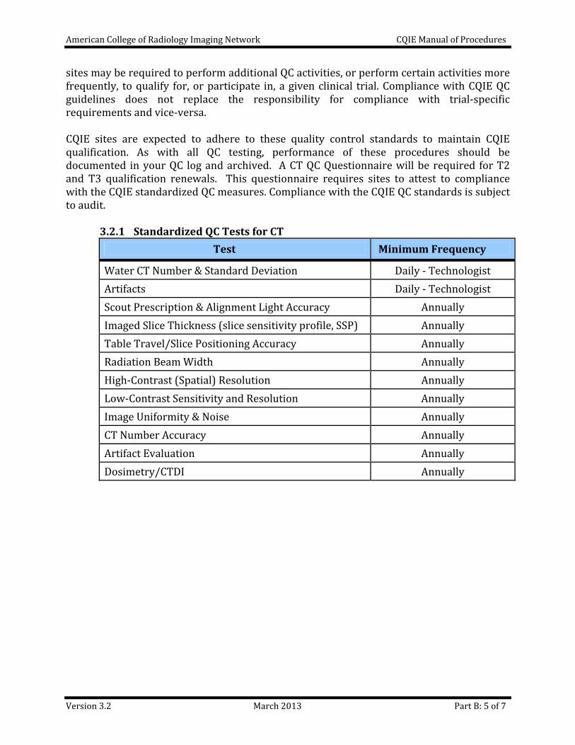
3.2.1 Standardized QC Tests for CT
Test Minimum Frequency
Water CT Number & Standard Deviation Daily ‐ Technologist
Artifacts Daily ‐ Technologist
Scout Prescription & Alignment Light Accuracy Annually
Imaged Slice Thickness (slice sensitivity profile, SSP) Annually
Table Travel/Slice Positioning Accuracy Annually
Radiation Beam Width Annually
High‐Contrast (Spatial) Resolution Annually
Low‐Contrast Sensitivity and Resolution Annually
Image Uniformity & Noise Annually
CT Number Accuracy Annually
Artifact Evaluation Annually
Dosimetry/CTDI Annually

American College of Radiology Imaging Network CQIE Manual of Procedures
Version 3.2 March 2013 Part B: 6 of 7
4. DATA SUBMISSION
4.1 Qualification Data
Submit the following data for each scanner to be qualified.
Time Point
Procedures Data
T0‐T3 ACR CT Phantom Tests
Volumetric Chest Protocol data set Volumetric Liver Protocol data set Routine Abdomen Protocol data set
T0‐T3 Clinical Test Case Volumetric Chest CT (if requested)
T1‐T3 Image Transmittal Worksheet Scanner specifications Notification to ACRIN of data submission
T2‐T3 Quality Control Quality Control Questionnaire
Clinical Test Cases Images must be submitted in DICOM format. Patient identifiers must be scrubbed from the clinical images before transmission to ACRIN. Data Submission Images must be submitted in DICOM format. Imaging should be transmitted to ACRIN electronically via secure file transfer protocol (FTP), if necessary images can be sent on CD‐ROM. Download and installation instructions for FTP setup are provided in Part A of this MOP, Appendix A2. An Image Transmittal Worksheet (ITW) should accompany each image submission. Refer to the CQIE web site, http://ww.acrin.org/NCI‐CQIE.aspx, for all qualification materials, including the ITW. If necessary images can be sent on CD‐ROM. Sites submitting images via CD should mail the package, including a copy of the ITW, to the ACRIN Imaging Core Lab at the address below. Method of shipment should include package tracking.
ACRIN Imaging Core Lab, # CQIE‐CT American College of Radiology 1818 Market Street, Suite 1600
Philadelphia, PA 19103

American College of Radiology Imaging Network CQIE Manual of Procedures
Version 3.2 March 2013 Part B: 7 of 7
5 References
American Association of Physicists in Medicine. AAPM Report No. 74: Quality Control in Diagnostic Radiology, 2002
American Association of Physicists in Medicine. AAPM Report No. 111: Comprehensive Methodology of Radiation Dose in X‐Ray Computed Tomography, 2010
American College of Radiology. ACR Technical Standard for Diagnostic Medical Physics Performance Monitoring of Computed Tomography (CT) Equipment
American College of Radiology. ACR Practice Guideline for Performing and Interpreting Diagnostic Computed Tomography (CT)
Imaging Working Group (IWG), Clinical Translational Science Awards (CTSA). Quantitative Imaging Biomarkers Alliance (QIBA), Radiological Society of North America (RSNA).

CQIE MOP Appendix B1
CT PHANTOM TEST INSTRUCTIONS: ACR CT PHANTOM
Version 3.2 March 2013 1 of 7
This document provides detailed instructions for performing phantom tests with the ACR Accreditation CT phantom (Gammex 464). Though based on the ACR CT Accreditation testing, modifications were made for the purpose of CQIE qualification. If your site does not own an ACR‐CT phantom, ACRIN will provide a phantom, on loan, or you may purchase your own. Additional information regarding the phantom loan procedures will be included in your site visit packet. For purchasing information refer to the ACR web site.
1. ACR CT Accreditation Phantom
The ACR CT accreditation phantom has been designed to examine a broad range of scanner parameters. These include:
Positioning accuracy CT number accuracy Slice width Low contrast resolution
High contrast (spatial) resolution CT number uniformity Image noise
The ACR CT accreditation phantom is a solid phantom containing four modules and is constructed primarily from a water‐equivalent material. Each module is 4‐cm in depth and 20‐cm in diameter. There are external alignment markings scribed and painted white (to reflect alignment lights) on EACH module to allow centering of the phantom in the axial (z‐axis, cranial/caudal), coronal (y‐axis, anterior/posterior), and sagittal (x‐axis, left/right) directions. There are also “HEAD”, “FOOT”, and “TOP” markings on the phantom to assist with alignment.
4 3 2 1
20 cm
4 cm
Head Foot
Alignment Alignment
CT # CT #
Slice width Slice width
Low contrastLow contrastresolutionresolution
UniformityUniformity& noise& noise
DistanceDistanceaccuracyaccuracy
& SSP& SSP
High contrastHigh contrastresolutionresolution
Figure 1: Diagram of the four modules of the ACR CT accreditation phantom.
S140 0 I20

CQIE MOP Appendix B1
CT PHANTOM TEST INSTRUCTIONS: ACR CT PHANTOM
Version 3.2 March 2013 2 of 7
Phantom Module 1 is used to assess positioning and alignment, CT number accuracy, and slice thickness. The background material is water equivalent. For positioning, the module has 1‐mm diameter steel BBs embedded at the longitudinal (z‐axis) center of the module, with the outer surface of the BB at the phantom surface at 3, 6, 9, and 12 o’clock positions within the field of view (19.9‐cm center to center). To assess CT number accuracy, there are cylinders of different materials: bone‐mimicking material (“Bone”), polyethylene, water equivalent material, acrylic, and air. To assess slice thickness, two ramps are included which consist of a series of wires that are visible in 0.5‐mm z‐axis increments.
Figure 2: Cross‐sectional diagram of (a) module 1, (b) module 2, (c) module 3, and (d) module 4. Phantom Module 2 is used to assess low contrast resolution. This module consists of a series of cylinders of different diameters, all at 0.6% (6 HU) difference from a background material having a mean CT number of approximately 90 HU. The cylinder‐to‐background contrast is energy‐independent. There are four cylinders for each of the following diameters: 2‐mm, 3‐mm, 4‐mm, 5‐mm, and 6‐mm. The space between each cylinder is equal to the diameter of the cylinder. A 25‐mm cylinder is included to verify the cylinder‐to‐background contrast level.

CQIE MOP Appendix B1
CT PHANTOM TEST INSTRUCTIONS: ACR CT PHANTOM
Version 3.2 March 2013 3 of 7
Phantom Module 3 consists of a uniform, tissue‐equivalent material to assess CT number uniformity. Two very small BBs (0.28‐mm each) are included for optional use in assessing the accuracy of in‐plane distance measurements. Phantom Module 4 is used to assess high contrast (spatial) resolution. It contains eight bar resolution patterns: 4, 5, 6, 7, 8, 9, 10 and 12 lp/cm, each fitting into a 15‐mm x 15‐mm square region. The z‐axis depth of each bar pattern is 3.8‐cm, beginning at the Module 3 interface. The aluminum bar patterns provide very high object contrast relative to the background material. Module 4 also has four 1‐mm steel beads, as described for Module 1.
2. Test Preparation and Phantom Set Up
Calibrate the Scanner: Prior to scanning the ACR‐CT phantom, perform tube warm‐up and any necessary daily calibration scans as recommended by the manufacturer. The ACR recommends that the site’s water phantom be scanned and tested for accuracy of the CT number of water, absence of artifacts, and uniformity across the field of view prior to proceeding with the phantom test. If problems are found, contact your field engineer or medical physicist for resolution. Do not proceed with the phantom testing until the issues are resolved.
Required Testing Materials:
ACR CT phantom
Phantom base
Level
CQIE CT Phantom Data Worksheet
Phantom Set Up:
Pull back the table padding and position the ACR CT accreditation phantom so that it is “HEAD” first into the gantry. (Be sure to choose a patient orientation of “head first” on the scanner.) Carefully position the phantom so that the CT scanner’s alignment lights are accurately positioned over the scribe line corresponding to the center of Module 1 (FOOT END of the phantom). Using the set of alignment lights (internal or external) that is used clinically, align the phantom in the sagittal, coronal and axial planes, and “zero” (or landmark) the table – all scans will be acquired in reference to this location (S0). While maintaining careful alignment, secure the phantom so it will not move (Figure 3).
Figure 3

CQIE MOP Appendix B1
CT PHANTOM TEST INSTRUCTIONS: ACR CT PHANTOM
Version 3.2 March 2013 4 of 7
3. Phantom Scans
For the CT portion of the CQIE qualification you are asked to scan the ACR CT phantom using three different acquisition protocols, as specified below. When setting up the scans, enter your institution name in the patient name field (see example below).
Patient Name: CQIE Name of Your Cancer Center (ex. ACRIN Cancer Center)
Phantom Scan 1: CQIE Volumetric Chest Protocol
CQIE Volumetric Chest Protocol If your site is performing this test for the first time you will need to build an acquisition protocol and save it to your scanner’s protocol menu, this may require special user permissions.
Start with a high resolution AXIAL chest protocol and modify the acquisition parameters to match those listed below in Table 1.
Patient orientation should be head first.
A topogram (scout) is optional and should not be necessary.
Only a standard body reconstruction algorithm is required. Turn off (delete) any other reconstruction algorithms that may be part of the selected protocol.
Turn off/do not use any type of automatic dose reduction technique.
Phantom Scan
Position phantom and set landmark (“zero”) as described above in Section 2.
Using the CQIE vCT Chest protocol, scan the phantom from I20 to S140 (‐20 to +140).
Save the image set for future QA/QC reference.
Table 1: Volumetric Adult Chest CT Protocol
Parameter GE Philips Siemens Toshiba
Display FOV (Reconstruction FOV)
21 cm 210 210 21 cm
Reconstructed Slice Width
1.25 mm 1.25 mm 1 – 1.5 mm 1 – 1.5 mm
Reconstruction Algorithm
STD B B30f FC10
Matrix 512 x 512
Scan FOV Small Body
mAs 240 + 20
kVp 120
Scan Mode Axial

CQIE MOP Appendix B1
CT PHANTOM TEST INSTRUCTIONS: ACR CT PHANTOM
Version 3.2 March 2013 5 of 7
Phantom Scan 2: Adult Volumetric Liver Protocol Start with your routine volumetric liver protocol then follow the bulleted steps below. Phantom Scan 3: Routine Adult Abdomen Protocol Start with your routine adult abdomen protocol then follow the steps below.
Position the phantom and set landmark (“zero”) as described above in Section 2. Modify the selected acquisition protocol to match the parameters below in Table 2. Only the standard reconstruction algorithm is required. You can turn off (delete)
any other reconstruction algorithms that may be part of the selected protocol. Turn off/do not use any type of automatic dose reduction technique. Patient orientation should be head first Scan the phantom from I20 to S140 (‐20 to +140). Save the image set t for future QA/QC reference.
Table 2: Acquisition Parameters for Phantom Scans 2 and 3
Protocol Scan FOV
Display FOV
Slice WidthRecon
Algorithm Scan Mode
2 Volumetric
Liver
Small Body
(or ~ 25 cm) 21‐25 cm 2.5 – 3 mm
Per Routine Clinical Protocol
Helical
3 Adult
Abdomen
Large
(or ~ 50 cm) 38 cm 5 mm
4. Image Evaluation
Now that you have acquired all of the phantom scans you should evaluate the images for pass/fail criteria, as described below, before submitting the images to ACRIN for analysis. The CT Phantom Data Worksheet, provided as Appendix B2, is an optional tool for which you can document the results of your evaluation. The worksheet is not required as part of your data submission to ACRIN. If the images do not pass one or more of the tests you, should consult your physicist or supervising physician as corrective action and/or repeat imaging may be warranted. 4.1 Scanner Alignment Test
Evaluate for the Volumetric Chest dataset only. Display the image obtained at “0.0”. Manipulate the window and level settings to allow you to best visualize the phantom, a typical setting for this is WW=1000 and WL=0. Visually examine the images. All four BBs should be visible at S0 as well as S120, as depicted in Figures 4a‐b.

CQIE MOP Appendix B1
CT PHANTOM TEST INSTRUCTIONS: ACR CT PHANTOM
Version 3.2 March 2013 6 of 7
4.2 CT Number Calibration
Evaluate for all protocol data sets. Select the best Module 1 image, (~I4‐S6) making sure that the image shows the longest wire + 1 wire from the center of at least one of the top and bottom ramps. Place a circular region of interest (ROI), approximately 200‐mm2 in size, within each cylinder (as shown in Figure 5) and record the mean CT number for each material for your records. It is important to center the ROIs within each cylinder. For each of the other phantom image sets, measure only the mean CT number for water. To pass, the mean HU of the material must fall within the recommended range. The pass criteria for the CT Number Calibration test are shown in Table 3. NOTE: If the mean material HU from the abdomen protocol fails, try to rescan with a smaller FOV (21‐25 cm).
Figure 4a. BBs visible at scan location S0 Figure 4b. BBs visible at scan location S120
Table 3:
CT Number Pass Criteria
Material CT Number (HU)
Bone +850 to +970
Air ‐1005 to ‐970
Acrylic +110 to +135
Water ‐7 to +7
Polyethylene ‐170 to ‐87
Figure 5: Cross‐sectional image of Module 1 with properly placed ROIs.

CQIE MOP Appendix B1
CT PHANTOM TEST INSTRUCTIONS: ACR CT PHANTOM
Version 3.2 March 2013 7 of 7
4.3 Low Contrast Criteria (Contrast‐to‐Noise Ratio) (CNR)
Evaluate for Abdomen and Liver datasets only. View the image located at the center of Module 2. Manipulate the window and level settings to allow you to best visualize the cylinders, a typical setting for this is a window and level setting of WW=100 and WL =100. Note that there are four cylinders for each of the following diameters: 2, 3, 4, 5, and 6‐mm (as in Figure 2b). Place a ROI, approximately 100‐mm2 in size, over the large 25‐mm diameter cylinder and next to the large cylinder (as in Figure 6). Record the mean signal in the ROI inside the 25‐mm rod (A), the mean signal in the ROI outside the 25‐mm rod (B), and the Standard Deviation (SD) of the ROI outside the 25‐mm rod (B) for your records. Use this formula to calculate the Contrast to Noise Ratio (CNR): CNR = |B‐A| / SD Use the absolute value‐ that is, do not take into consideration whether the CNR is a positive or negative number. The CNR must be greater than 1.0 for the abdomen and greater than 0.75 for the liver.
A
B
Figure 6: Module 2 low contrast resolution image at
WW = 100 and WL = 100 with correct ROI placement.

CQIE MOP Appendix B2
CT PHANTOM DATA WORKSHEET
Version 3.2 March 2013 1 of 1
Are all four BBs visible at S0? Are all four BBs visible at S120? Yes No
S0
S120
4.1 Scanner Alignment Test (evaluate for volumetric chest data set only):
4.2 CT Number Calibration (evaluate for all protocol data sets):
Record the mean CT number for each material (HU)
Material Pass Criteria Chest Liver Abd
Bone +850 to +970
Air ‐1005 to ‐970
Acrylic +110 to +135
Water ‐7 to +7
Polyethylene ‐170 to ‐87
4.3 Low Contrast CNR (evaluate for abdomen and liver data sets only)
Series Mean A Mean B SD CNR = |B – A| / SD
Abd
Liver
Pass Criteria: Abd CNR > 1.0
Liver CNR > 0.75
WW = 400WL = 0
“Bone”
Water
Poly
Acrylic Air


